HOLIDAY DONATION DRIVE - SUPPORT MSW - DO YOUR PART TO KEEP THIS GREAT FORUM GOING! (Only 51 donations so far out of 49,000 members - C'mon guys!)
×


FriedClams
-
Posts
1,368 -
Joined
-
Last visited
Content Type
Profiles
Forums
Gallery
Events
Everything posted by FriedClams
-
 Nice to see your updates again Keith. Very fine modeling as always and I like your method for truing the masts. Clever. Gary
 -
I went through your log over a couple of sessions Craig and dang, what a model and how beautifully you have built her. You make that ultra tiny detail work look easy which of course we all know - it is not. Congratulations on a fine build. Gary
- 174 replies
-
- 3
-

-
- prinz eugen
- trumpeter
- (and 2 more)
-
Just catching up on your beautiful model construction Grant. This is going to be a real show piece. First class job and terrific painting. Gary
-
Just catching up OC. Wonderful progress - you have been busy! And as always your figure painting is spectacular! Gary
-
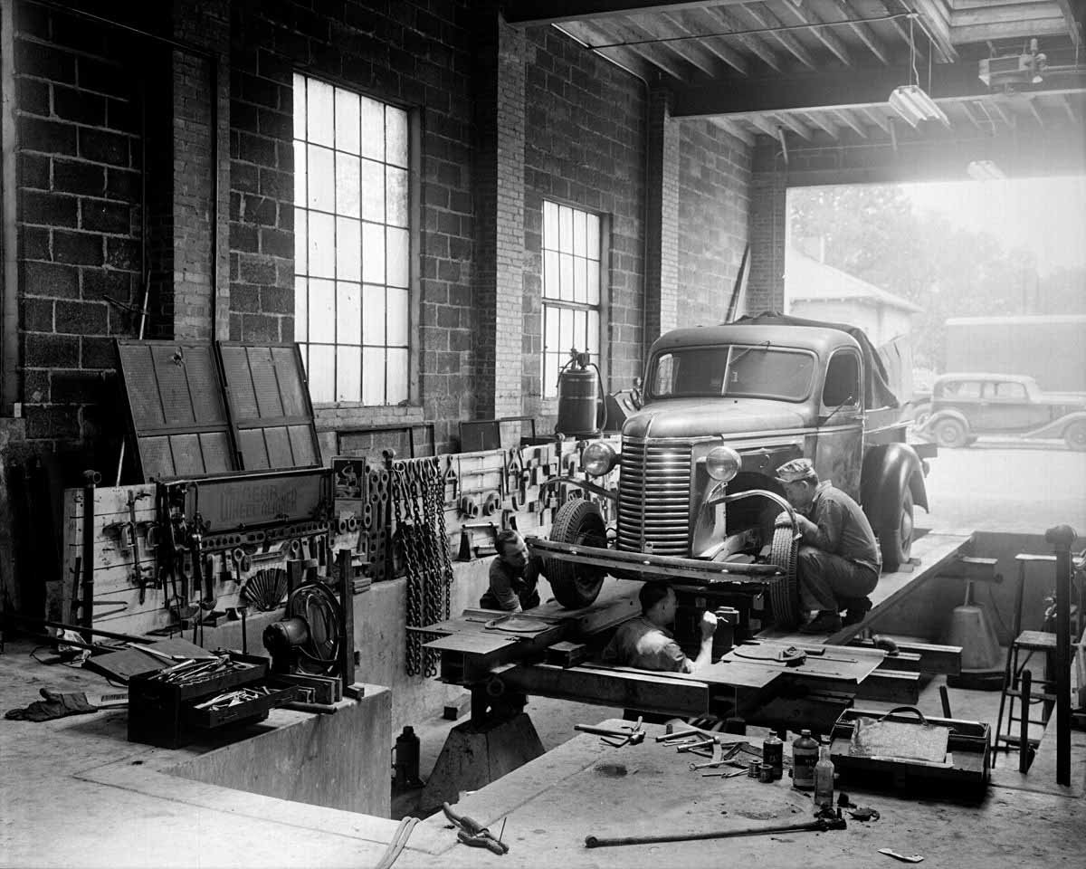
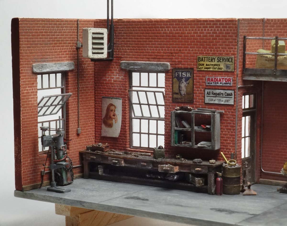
Hello All - thanks for the likes and for stopping in to take a look. Hi Mark. More room would be nice and to do it over I would make it just a tad wider. Even just an inch or so would help, but then again, I'm really just trying to create an atmosphere and as you say more clutter may actually hurt the model. Yes – real world clutter is totally overwhelming and beyond my patience and abilities. It does seem like a matter time before someone drops a tire off the edge/end, but here's the inspiration photo. This looks like a staged or promotional photo for sure, but then again . . . Thanks for the comment Wefalck. Thanks CDW for the nice comment, it's good to hear the dio brings to mind a real place. To be honest Keith and as strange as it may sound, I don't know if there is a wall there. I've kind of left it up to the viewer to decide if what is shown is the whole shop or just a corner of it. Is the viewer standing in the middle of a larger garage with other service bays behind him, or as you say - looking through a wall? Hmmm. Either way, your suggestion is a good one and please don't be reluctant in offering your thoughts - I have always greatly valued your input. Reconsidering the arbor press, I may place it between the drill press and bench where the welding torch now sits. Because the torch is on wheels it could believably be placed anywhere. And something that has nagged at me is the knowledge that I placed it against the wall backwards. The torch kit would never sit the way I currently have it - with the tanks facing outward and the cart against the wall because you lean it back onto its wheels to roll it off. I'm going to move things around and see what I can come up with. Thanks for your suggestion and comment Keith. Hello Egilman. The problem in that back corner is that I have to keep it clear for the exterior door. I would have to move the barrel stand elsewhere because moving it much further to the left would pinch off the walking space between it and the pit safety railing. I am going to consider some repositioning of things. Thanks for the suggestion - more eyes and thoughts are always helpful. Hello TBlack. Thanks for looking in. The model railroading folks are the masters of modeling clutter – they do it so well! Thanks, Gary
- 189 replies
-
- 14
-
-
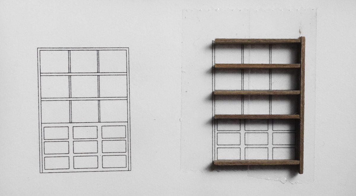
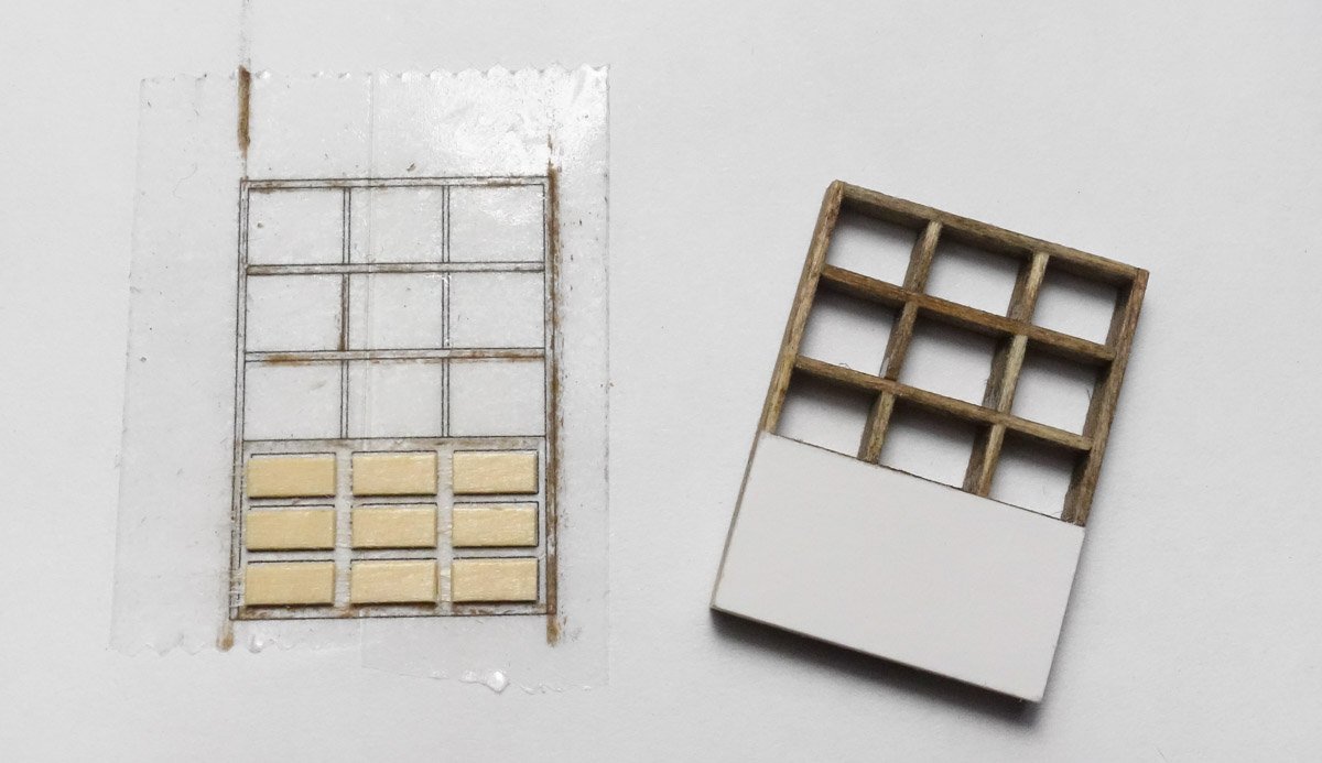
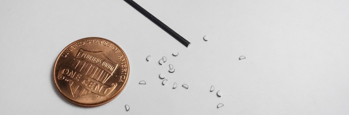
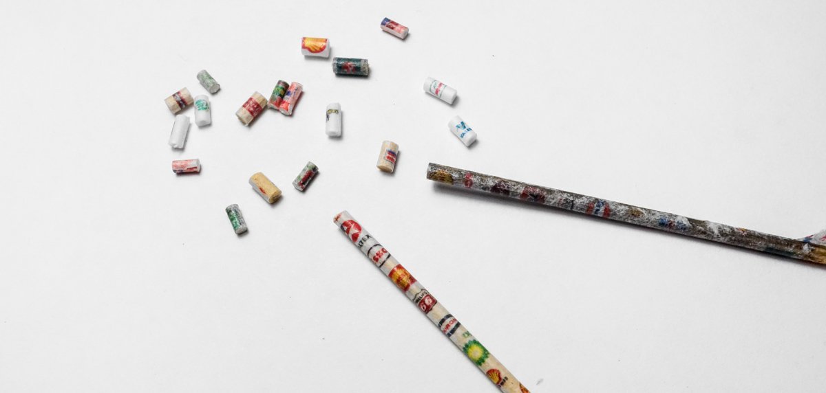
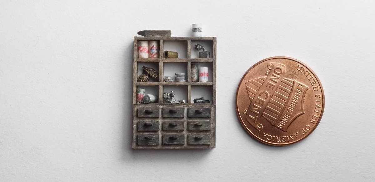
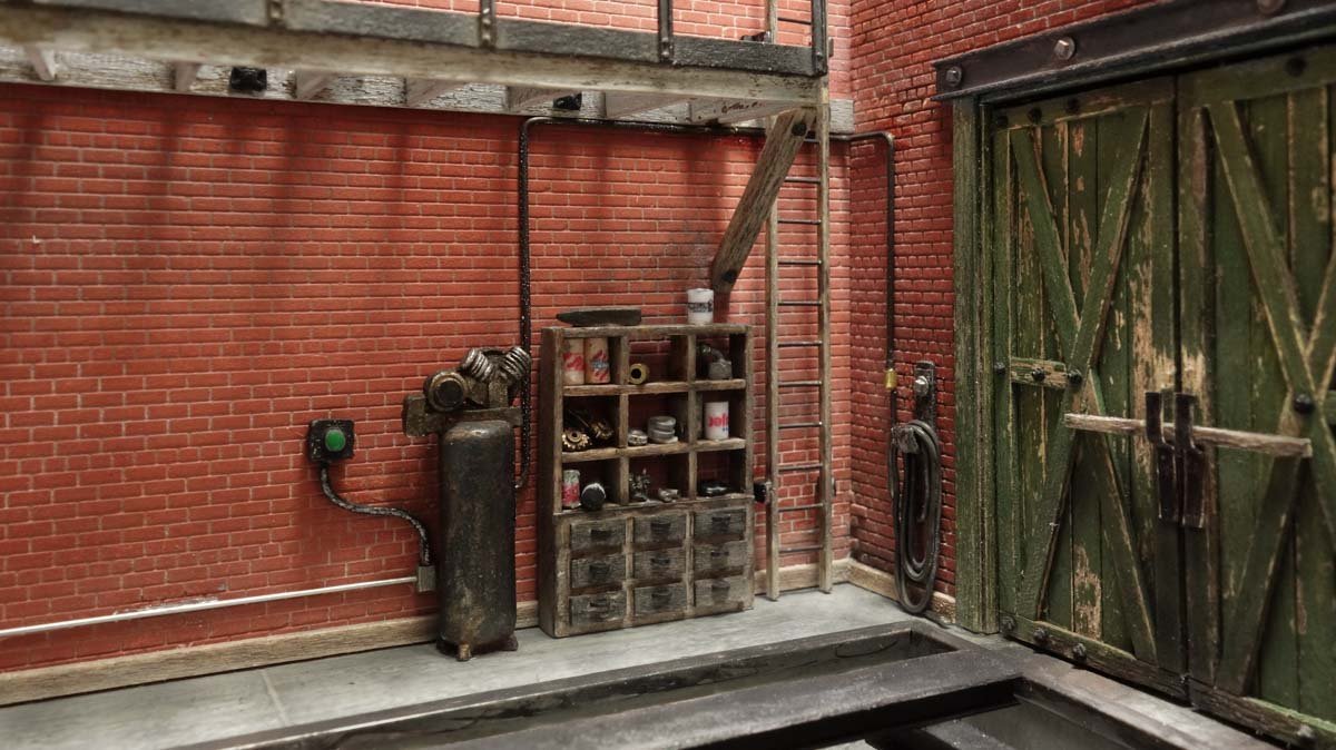
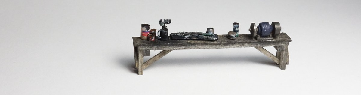
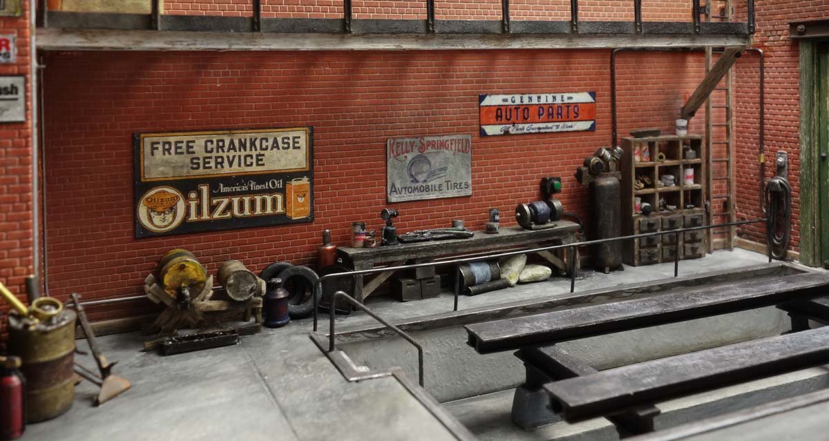
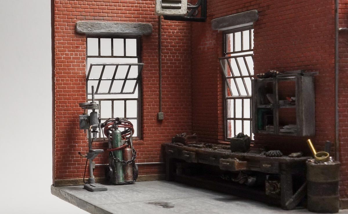
Greetings fellow modelers. Thank you all for your wonderful comments and the “likes”. After a couple of months away from modeling this little diorama has called me back. Wall Details and General Clutter I have finished populating the back wall with things, stuff and junk. Or at least I think I'm finished. In subjects like this, it seems there is never enough detail – never enough stuff. More and more items keep coming to mind that really should be included but mercifully I have run out of room. In fact, the arbor press I made back on post #38 will be left out because there is just no good place for it. That's always a risk making details in advance instead of letting the model tell you what is needed as it progresses. Anyway, here is a short update. A storage unit with drawers is made of basswood that was pre-stained. The face frame for the drawers is paper. The drawer fronts are stuck down on double sided tape and tiny specks of CA are applied to each, then the unit is flipped on top. The drawer pulls are slices of painted half-round styrene. The problem with cubbies and shelves is that you can't leave them empty. Cans are a good way to fill some of the holes and they are easy to make. Printing onto tissue paper then gluing it to wood dowels and/or styrene rod produces a decent can. It doesn't really matter what the print says because no one will be able to read it anyway. Other little bits of things are glued on. The compressor against the back wall is a white metal casting from Durango Press. I added a start station and “black iron” pipe that feeds the air hose by the door. The hose is blackened solder. A basswood bench is made. The bench grinder is a Rio Grande Scale Models piece and the torch came out of my junk box and I don't recall who cast it. The image below shows the completed back wall (the mezzanine above is still empty.) The barrel stand was made previously on post #48 and the remainder of the items are a combination of scratch and modified castings. Some of the wall signs I printed while others are from JL Innovations. All were sanded on the back side to reduce thickness and then dirtied up with ink/alcohol. The pit rail is .022” phosphor/bronze wire that was soldered together and blackened. Thanks for swinging by to take a look. Gary
- 189 replies
-
- 31
-

-
-
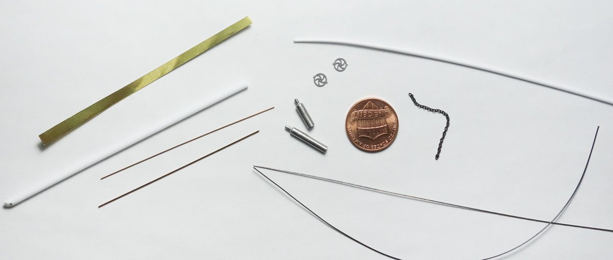
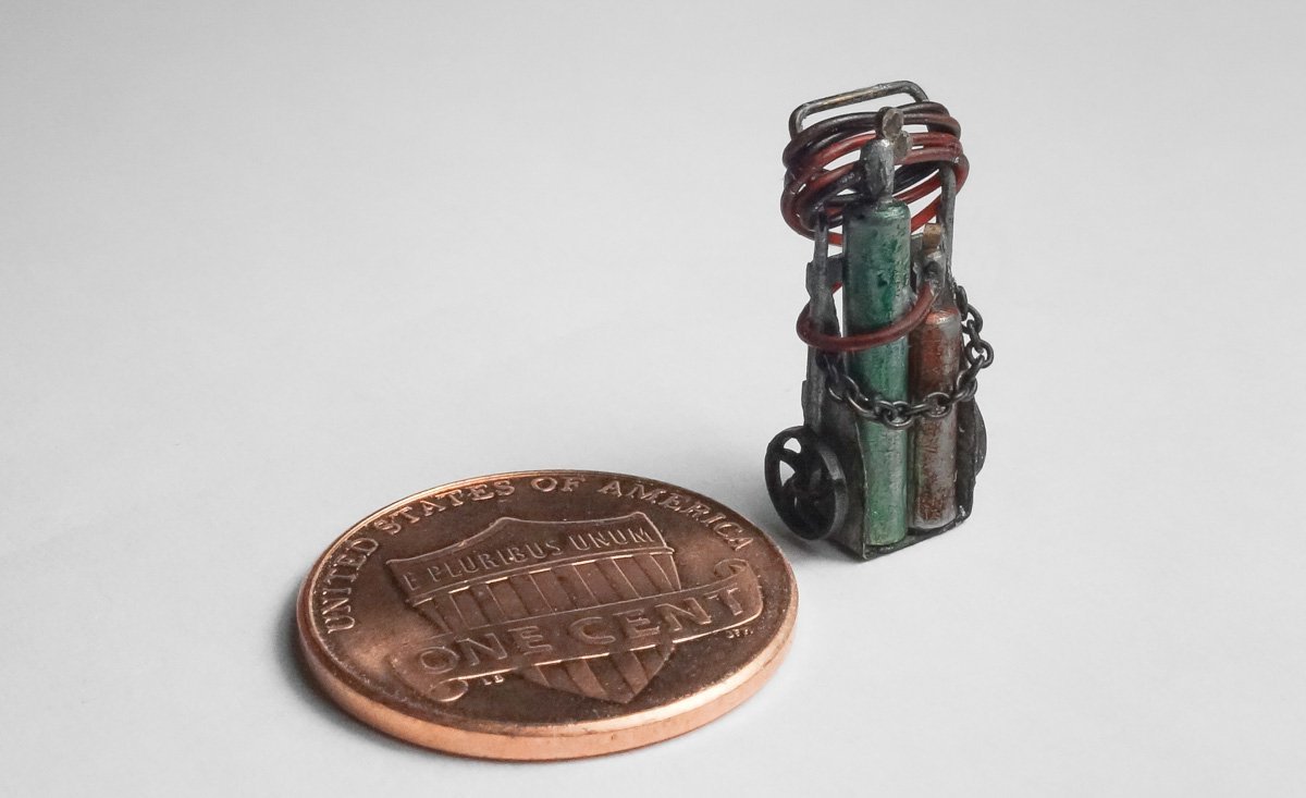
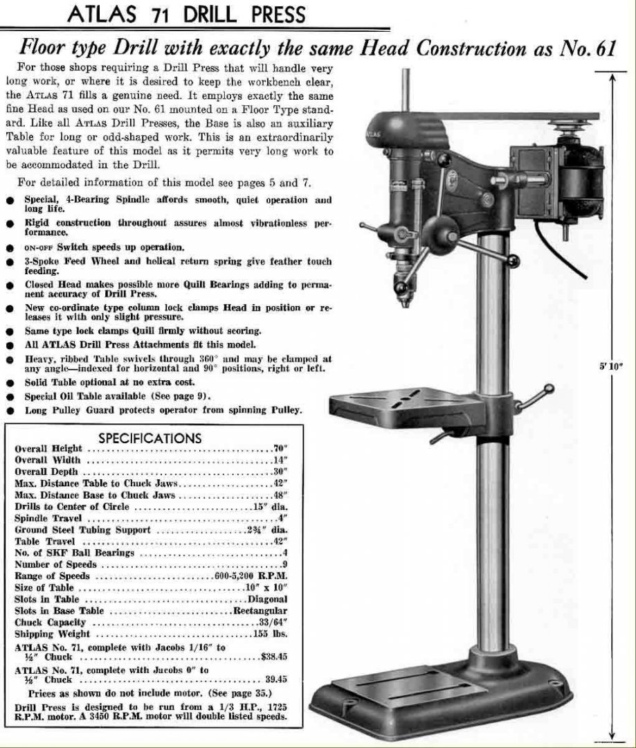
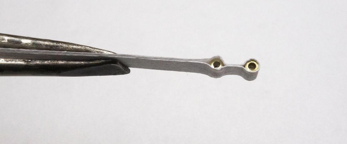
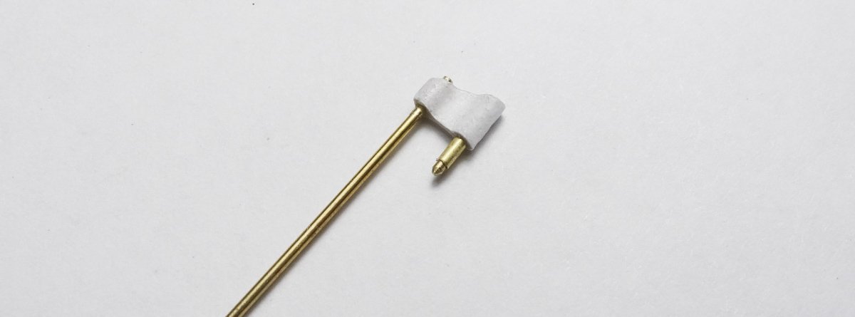
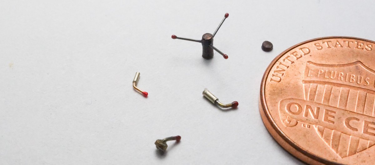
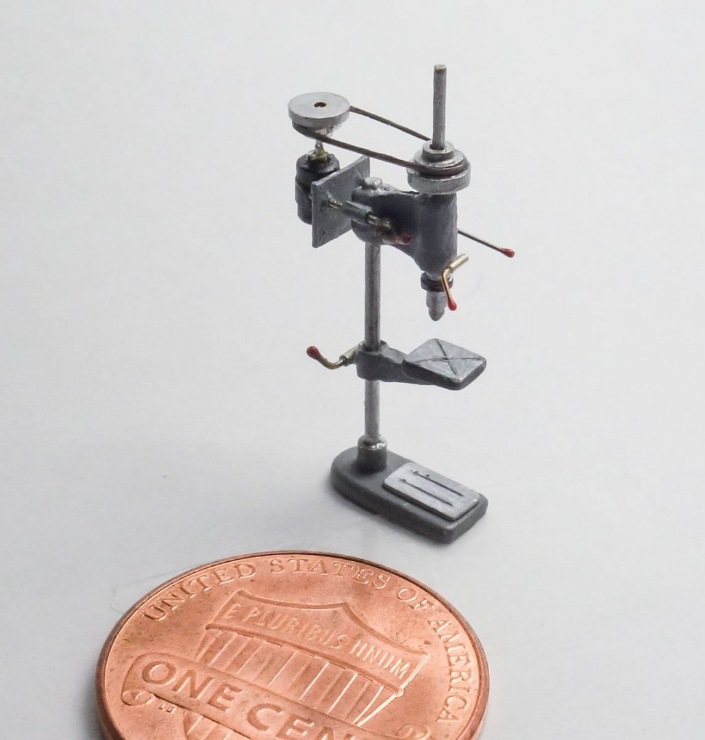
Thanks to everyone for the fine comments and suggestions - it is always so appreciated. And thanks for the likes and to those watching quietly. Not a bunch accomplished on the diorama in the last several weeks, but here's an update on what I have done. More Garage Equipment - Acetylene Torch I don't have any in-process photos to share with you on this torch. It was one of those constructions where I spent most of my time tossing things in the trash with nothing of value to show. In the end, I was happy just to get the thing finished, such as it is. I began by gathering materials - .005” brass shim stock, phosphor/bronze wire (.012” and .02” dia), assorted styrene rods, a scrap stick of white-metal that scaled to 9” dia., some chain, some insulated wire and a couple of injection molded wheels. The white-metal stick was cut into two lengths, chucked into my hand drill and worked with needle files until they resembled a pair of tanks. The cart is mostly brass and bronze soldered together. A brass wire axle was inserted through the cart and the wheels glued on. The tanks are colored with permanent markers for a translucent effect. Green oxygen and red acetylene are modern tank colors and probably not the standard in 1940. Conspicuous by its absence is the torch/nozzle itself, which I'm pretending is hanging behind the cart. So you may be wondering why I chose chain large enough to anchor a steamship for the tanks' safety chain. Actually, this chain is 40 LPI and I haven't found anything finer than this that still resembles actual link chain. Fine chain is so useful in modeling and if anyone knows a source please share. The hoses are also on the large side, but it's one of those strange eye/mind things where the proper size looked flimsy and wrong. Drill Press I need a piece of equipment to be positioned against the left wall and up front towards the shadowbox glass. Because it's right up front, it needs to be fairly detailed. I had originally intended for the arbor press to be placed there, but I now feel that in profile it isn't that interesting visually. And I wonder how many non-mechanical people would know what it is or what it's used for. So I decided on a floor drill press to fill the slot. It has an interesting shape and recognizable by most people. The arbor press will be stationed elsewhere. As a reference to build from I chose model #71 from Atlas Manufacturing that dates to 1933-36. Although it isn't mechanically complicated, it is of course the size that provides the challenge in making it. In 1:87 it is less that 7/8” (22mm) in height. It is a delicate little thing and a tad exasperating. I began with the spindle head which is simply two short sections of brass tubing wrapped in paper. The paper is the sticky part of a Post-It note and it holds things together long enough to saturate it with thin CA. You wouldn't know it by looking at the photo below, but the brass tube on the right is slightly larger than the one on the left as it accepts the main post. The lower part of the spindle is glued in and also the main post. The spindle is tapered to mimic a chuck and a thin wall brass tube is slid on over the top. I have a decent collection of fine brass and phosphor/bronze wire as well as a good selection of ultra fine tubing in brass, nickel and stainless. These materials proved to be very handy in making this drill press. I then made up the table/bracket from styrene and attached it to another section of tubing that will slide fit onto the main post. The base. I decided to leave out the spindle head pulley guard for two reasons. First, I wanted to show the pulleys and belt as a visual detail, and secondly (the honest reason) is that making a multi-dimensional cowl guard that is less than 1/8” in size would cause permanent psychological scarring. The pulleys are made by slide fitting brass tubing into one another and leaving an equal reveal between them. I soldered them together and cut off the pulley. The motor is made up and pulley added. This was simple to make because it's just pieces of round things fitting into other round things. The “bearings” are a single brass tube with a wire run through it which in turn slide fits into a piece of styrene tube. I added a band of paper around the center of the motor to suggest separate bearing bell housings. A second pulley was pushed onto a brass rod and glued into the spindle top. In the image below you can see a depth gauge has been added and a short horizontal tube that along with an identical one on the opposite side will hold the motor. Front view. Pushing two dress maker's pins through paper and into the motor mountings gave me the distance between the mounting rods which was then transferred to the motor base. The three spokes on the feed wheel are .008” phosphor/bronze chemically colored with Jax Flemish Gray. The ends of the wire were dipped into a craft product called Gallery Glass to create the knobs. The knobs will be painted black. The wheel center is styrene stretched to the diameter I wanted. Adjustment handles of different sizes were also made up. All that was left is to glue it together and add some paint. Touch ups are still needed as seen in the photo below, but I used enamel – silver, steel, gray and black. I added a styrene table face to the base. The belt is 8 lb. ice fishing jigging line and it has a sort of oval/flat cross section. Done. And both items are glued into place on the dio. Thanks for taking a look. Be safe and stay well. Gary


- 189 replies
-
- 26
-
-
-

-
Very interesting project Grant and you're off to a great start. I agree with Denis that paint selection can be the most difficult decision in a model. It can make or break the model. I've pulled up a seat. Gary
-
Sorry to hear of your wife’s fall OC. I wish her a quick recovery. Nice progress on the diorama. Gary
-
Great work O.C. I always enjoy catching up on your progress. Thanks for explaining the moment in time the dio will depict. Fascinating history and a brutal scene. Gary
-
Terrific work Brian - every bit of it. I particularly like your process in constructing the pitman arms. Adding the curved profile to each side by layering on extra material is a clever solution to maintaining perfect symmetry across both arms. I must remember that. Great update! Gary
-
Your model is looking very nice Dan. Great job mitigating the problems you’re finding in the kit. Gary
-
Teutonic knight c. 1200 by wefalck
FriedClams replied to wefalck's topic in Completed non-ship models
Excellent work Wefalck - so realistic. Gary -
Congratulations on finishing this wonderful model Eric. This has been an interesting log and a pleasure to follow. Gary
-
Wonderful finish Steve - Miss Mabel is looking sweet. Gary
-
The excellent work continues O.C. Very nice progress! Gary
-
Beautiful work on the Phantom, Egilman! Very nice. And what an amazing piece of machinery - grace, beauty and raw power in one package. Any progress on the Bell helicopters? Gary
-
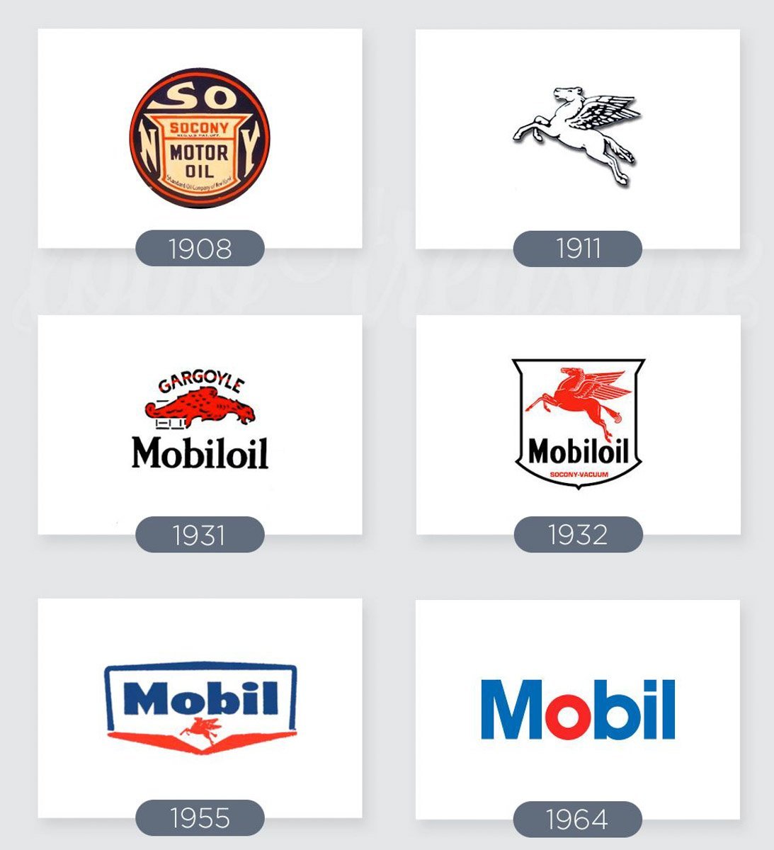
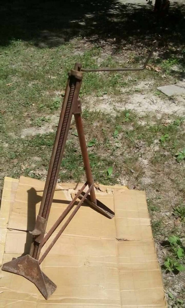
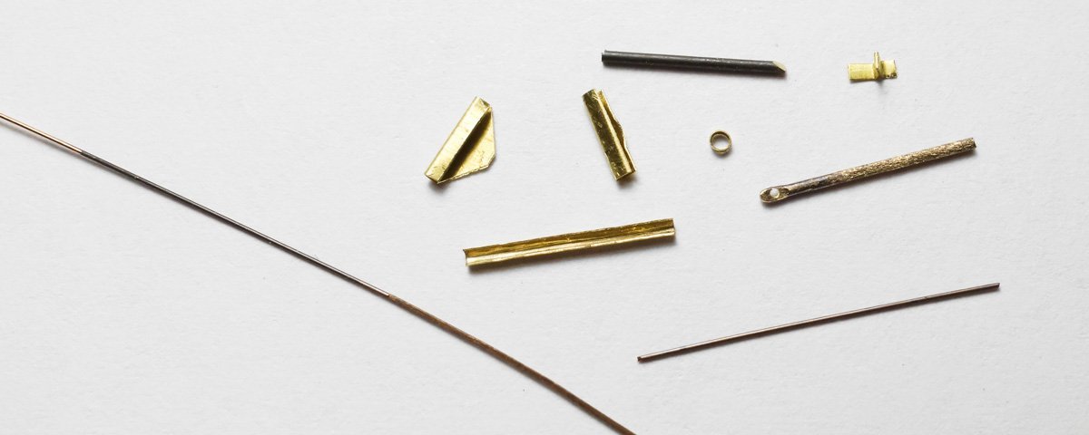
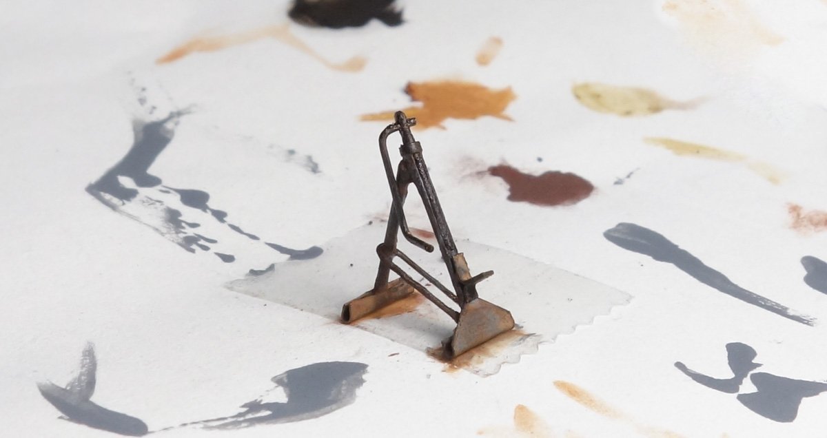
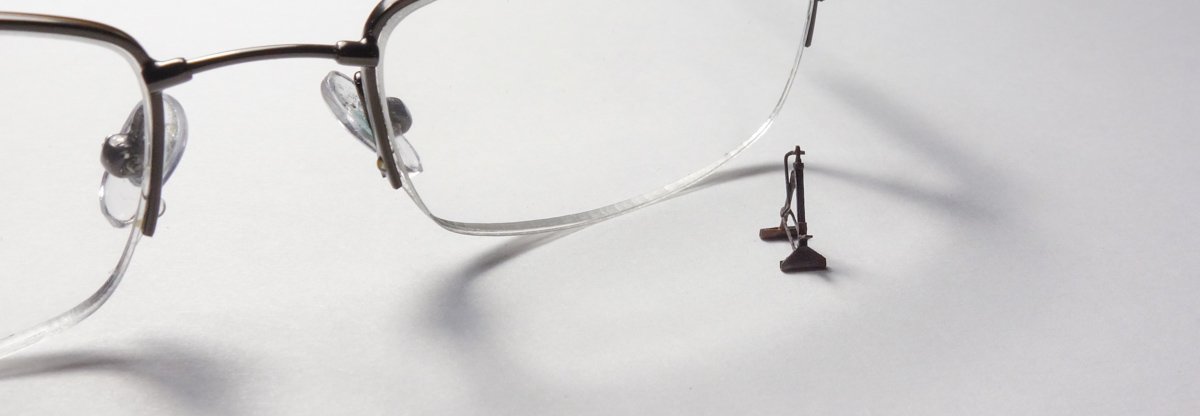
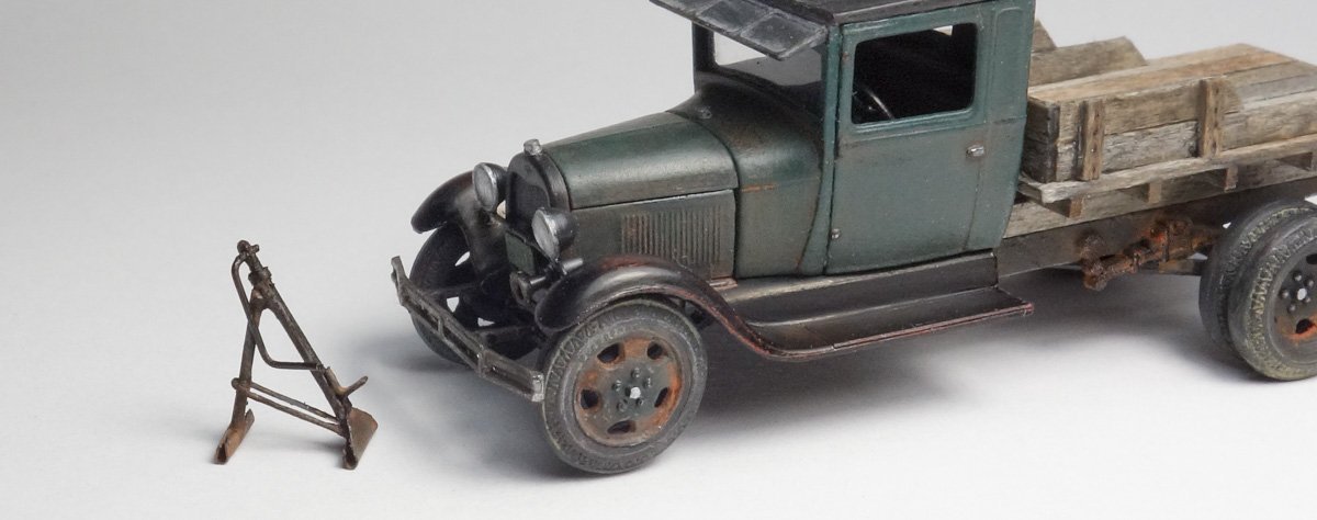
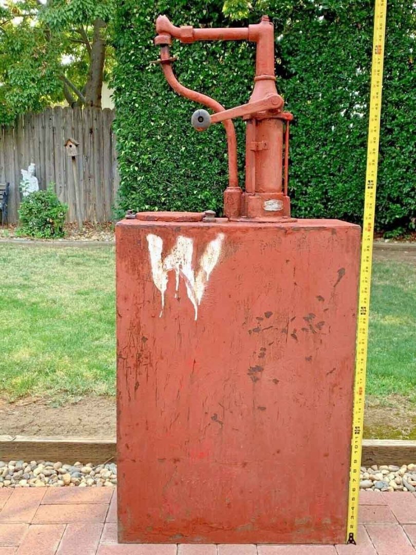
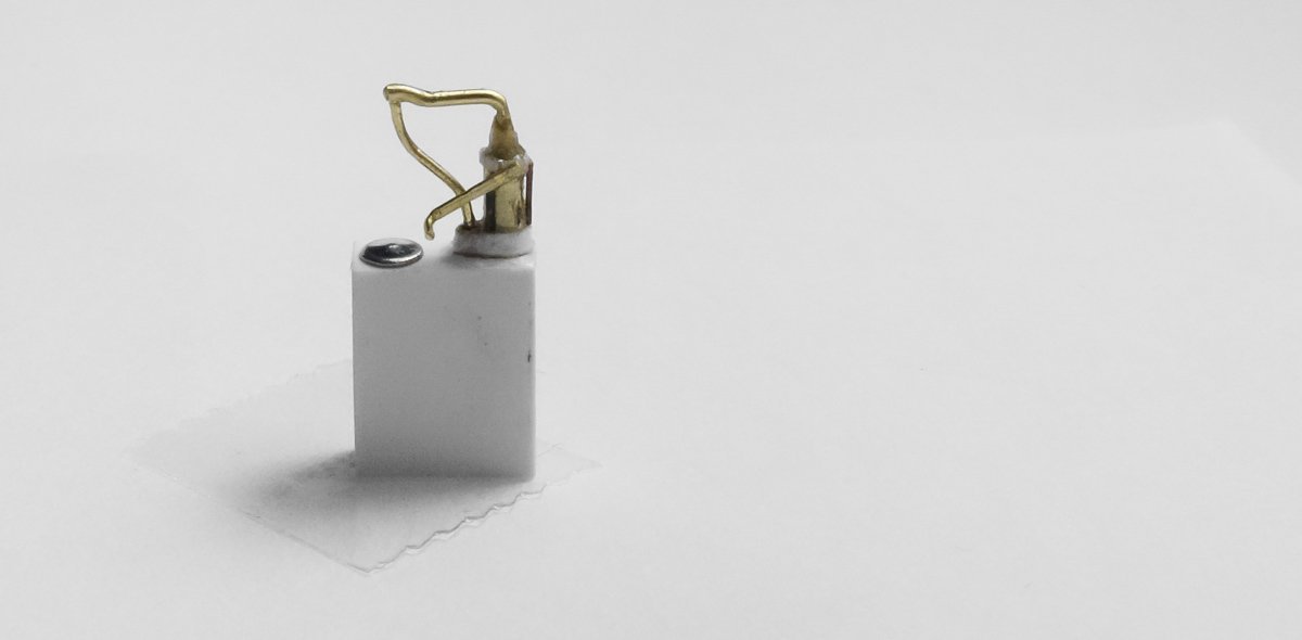
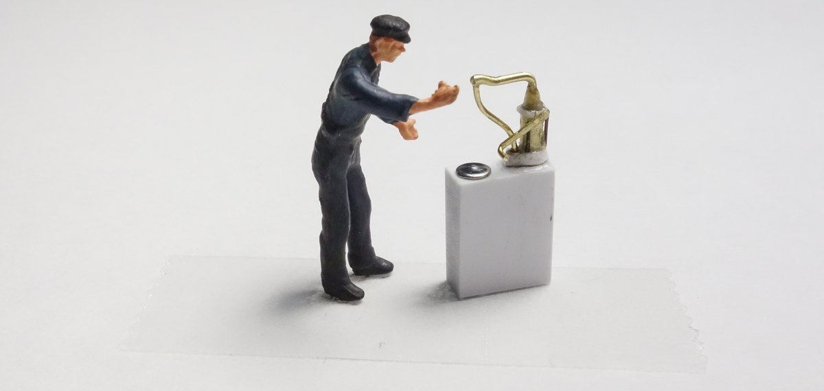
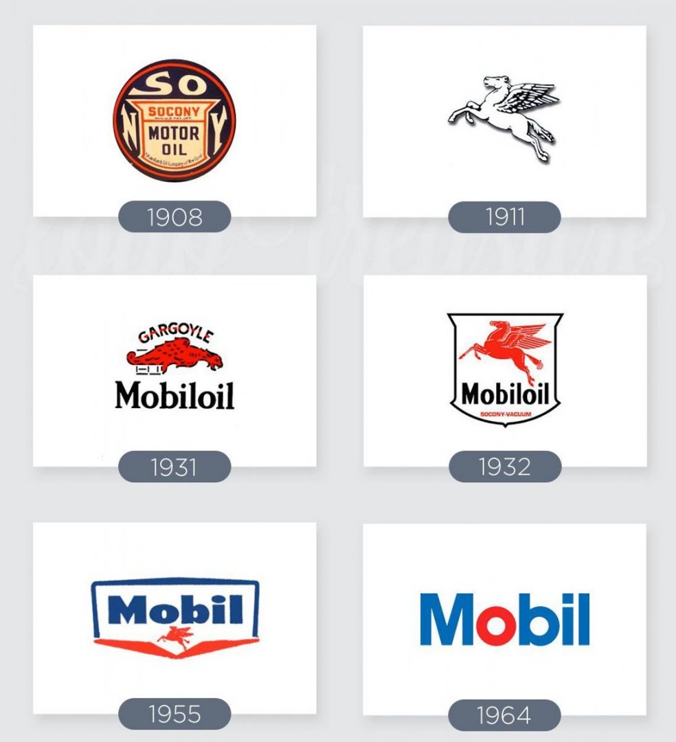
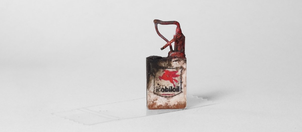
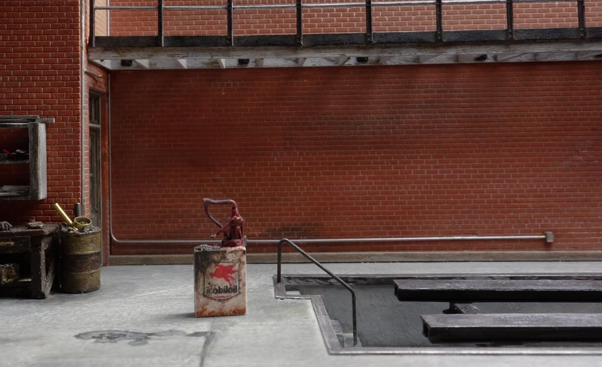
Thanks guys for the great comments - it is always so appreciated. And thanks to all for looking in and for the likes. Welcome Mark P and thanks for the nice words. Due to urgings from my wife, I now place a sticker somewhere on all my models with the date, name and so forth. I think it's a good idea for all us modelers. Thanks. Hello Denis. Yes that brown plastic is a little brittle and it probably won't get any softer as time goes on. Thanks. Yes Roger, I believe the Packard trucks were being marketed as a cut-above the ordinary vehicle, but I don't know if they were received that way by the public. Here is a short update. Back at post #35 @Egilman suggested that an old bumper jack of some sort might be an appropriate detail item for the diorama. I agree and so I put together a screw type jack using one of his posted photos as a guide. I also found a photo of a similar jack with a tape measure held next to it showing a height of about 32” with the back leg extended. I don't know the age of this particular jack, but I feel certain jacks of this type were in use during the late 30's and early 40's. Thanks for the suggestion Egilman. The jack is made mostly of brass. As evidenced by the mess shown below, I tried different color combinations before I settled on what you see. Looking at these close-ups, I see the feet are too large and it's leaning back too far - but I'm calling it good. I may fold it up and lean it against a wall which will solve at least one of the problems. Lubester Oil pumping dispensers like this one were once common and finding a photo with a measure in it was very helpful. This is a Phillips Pump and Tank Co. unit. I didn't take a “pre-assembly” photo, but you can see the bits and pieces here. A block of styrene, brass wire and tubing, paper and an aluminum disc all held together with CA gel. What ever is wrong with this fellow's hand, it looks painful. Now that I've decided on a vehicle to display, I'm free to add advertising and logos that fit the time period. Lubesters typically had oil company logos on them and I decided to place a Mobiloil Pegasus image on this one for no other reason than I like it. The history of break-ups and mergers of U.S. oil companies after Standard Oil Co. was dissolved in 1911 is long and convoluted. But in a overly simplified statement, Mobil came about when Standard Oil of New York (SOCONY) merged with Vacuum Oil in 1931. Primary logo changes during the period of 1908 to 1964 look like this. I laser printed the image onto tissue paper (gift wrapping type) and glued it on with PVA. Red enamel and black oil paint along with pigments are applied. It didn't need to be this grubby, but I got carried away. Thanks for swinging by. Gary
- 189 replies
-
- 24
-
-
-
-
Great progress Brian. The paint job looks terrific and a good choice on the cut-away color. Gary
-
Looking good Denis - very nice progress. Gary
-
Just catching up OC. and your farmhouse turned out great. I really like the interior work and the staircase looks particularly authentic. Love the image looking through the window. Very nice. Gary