

tlevine
-
Posts
1,956 -
Joined
-
Last visited
Content Type
Profiles
Forums
Gallery
Events
Posts posted by tlevine
-
-
-
I do not have any reference other than logic. If the rudder needed to be unshipped, at least some of the platform decking would need to be removed to raise the rudder high enough to clear the pintles. I am also guessing that it would be much easier to install the tiller if you could see the mortise in the rudder head, rather than blindly fishing around with a relatively heavy chunk of wood. Also, on the photo of the model, the center planks are missing, exposing the rudder head. Leaving only the center part of the platform unplanked was my original plan but as this is a POB model, the area looked too messy to leave open.
I much prefer the look of natural pear vs. swissed. I find the latter too pink. My understanding is that the steaming process makes the wood more stable but my billets are over 20 years old and show no cracking or warping.
-
There have not been any modifications to the half hull kit this year. Did you have something specific in mind?
-
-
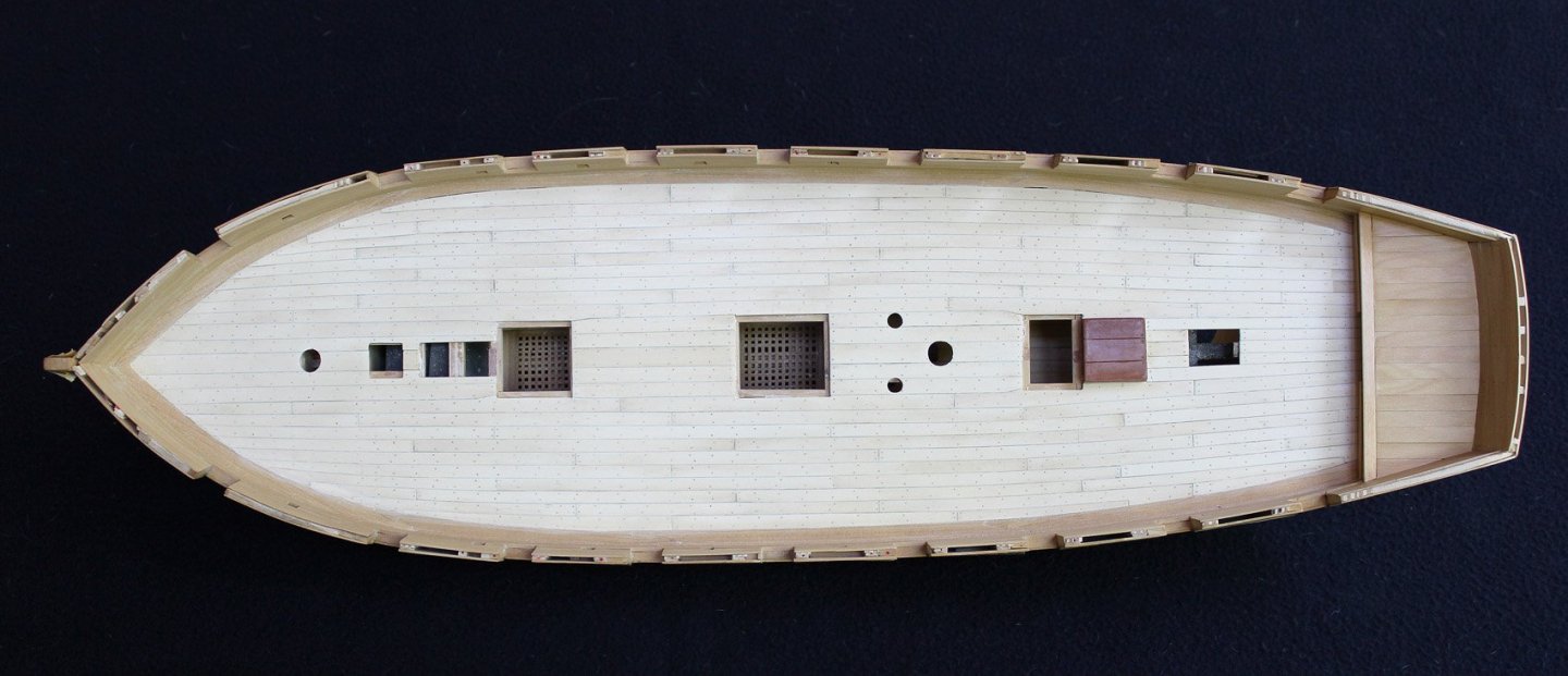
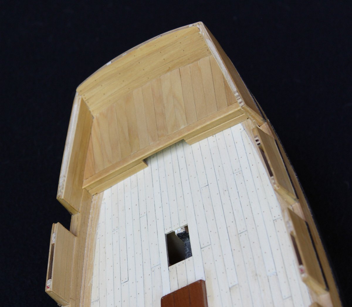
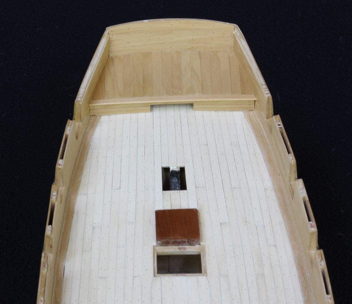
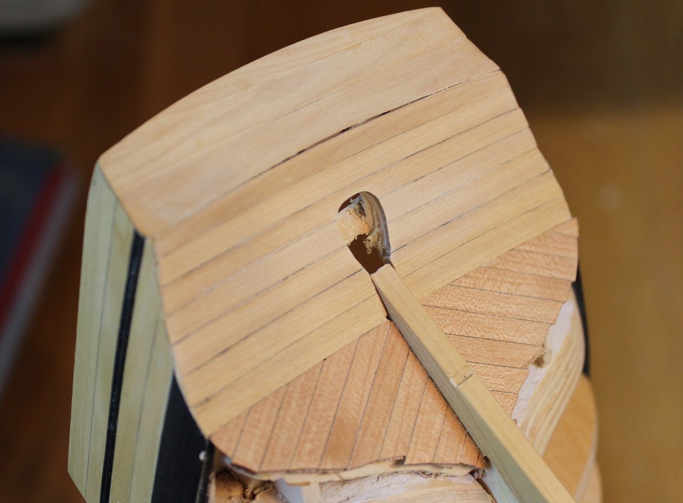
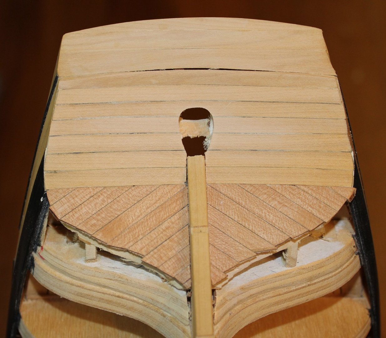
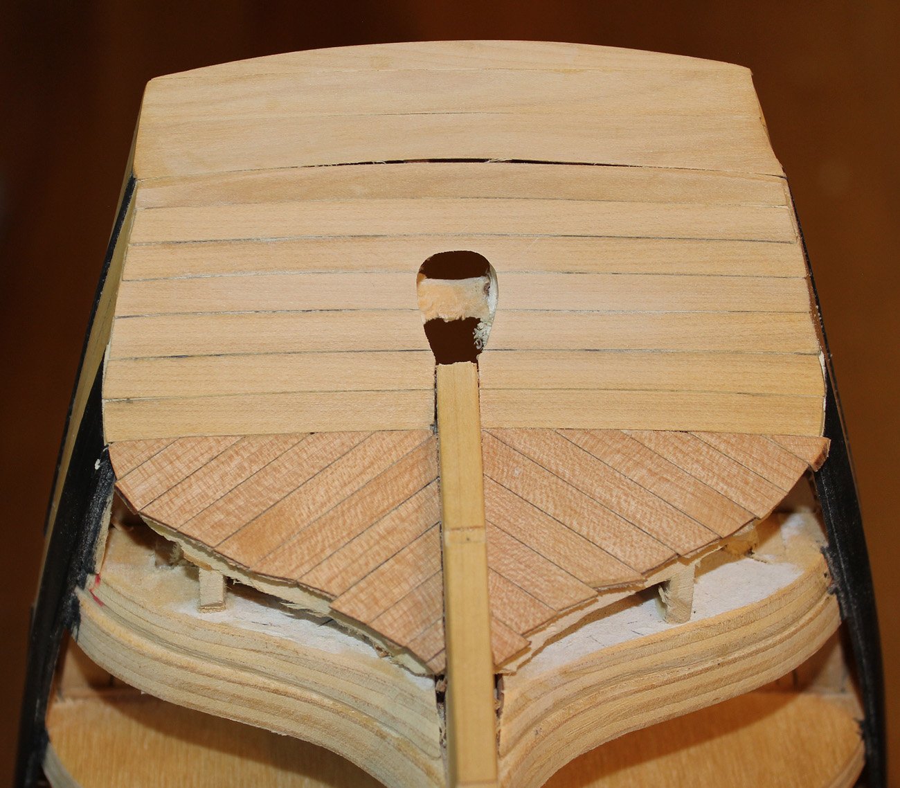
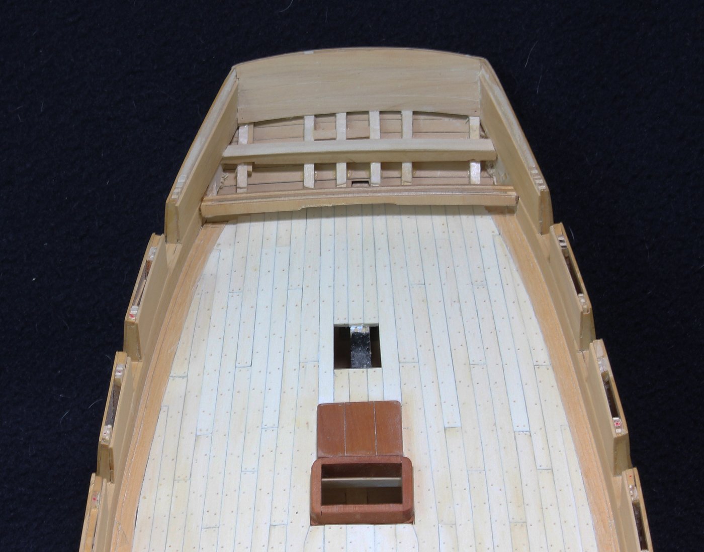
This is probably the last update for a few weeks. There is always so much to accomplish when the weather is nice. After the rudder was finished, I located where the tiller would have been inserted and made a square opening for it. I could now finish the platform. I viewed the platform as a lightweight structure which had no permanent fastenings. Boards could be removed to get access to the rudder head and the whole assembly could be disassembled for extra deck space when in action. For this reason I made the structure from box rather from the holly I was using as decking. For the same reason, there are no treenails. Later I will add ring bolts to facilitate removal of some of the boards. The model shows two rows of planking on the platform bulkhead. The lower row is thicker and I duplicated this here. The center opening is for the sweep of the tiller.
- Cathead, oneslim, michael mott and 13 others
-
 16
16
-
-
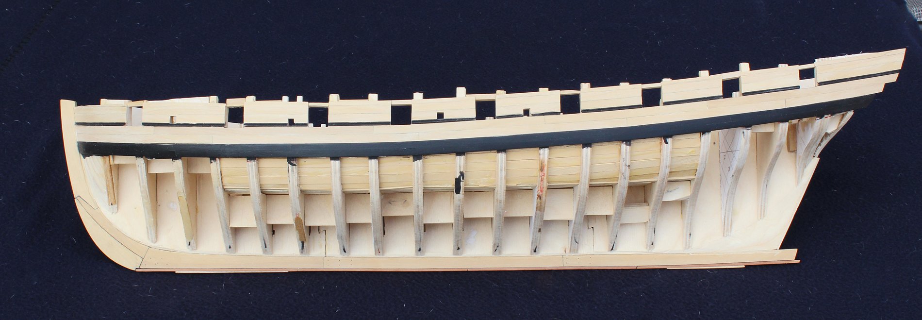
Having learned my sequencing lesson, I decided to make the rudder while I would still have access to the area under where the platform will be built. The shape of the rudder was taken off the plans except that it was shortened to just below the platform planking.
The rudder is made from three pieces: the main piece, the blade and the backing piece. The plans did not show a sole piece. The main and backing pieces were made with a simplified table joint and black paper was used to represent the felt between the two pieces. The width of the main piece mirrored the width of the sternpost; the blade tapered to 3" aft. The joints were initially all cut with a chisel but after making a mess of two blade blanks, I made the blade cuts on the mill.


The backing piece with its felt were added and the mortises for the pintles were made. A line was drawn on the fore end of the rudder, through the back of the pintle mortises; this is the bearding line. The for end of the rudder was then tapered from the bearding line to the midline of the fore rudder. This allowed the rudder to rotate freely with minimal gap between it and the sternpost. Finally, a coat of finish was applied.

An egg-shaped opening was made in the counter to accommodate the rudder head through its arc of rotation. I have also replaced some of the planks on the stern, eliminating the previous gap next to the sternpost.
-
Well, Druxey, there was not much in that bottle to begin with! This is the first time that I am building a model from plans I developed and without a specific sequence of construction. I should have consistently followed the same sequence set down in TFFM. But even though it is frustrating, I am learning an incredible amount from even my floundering.
-
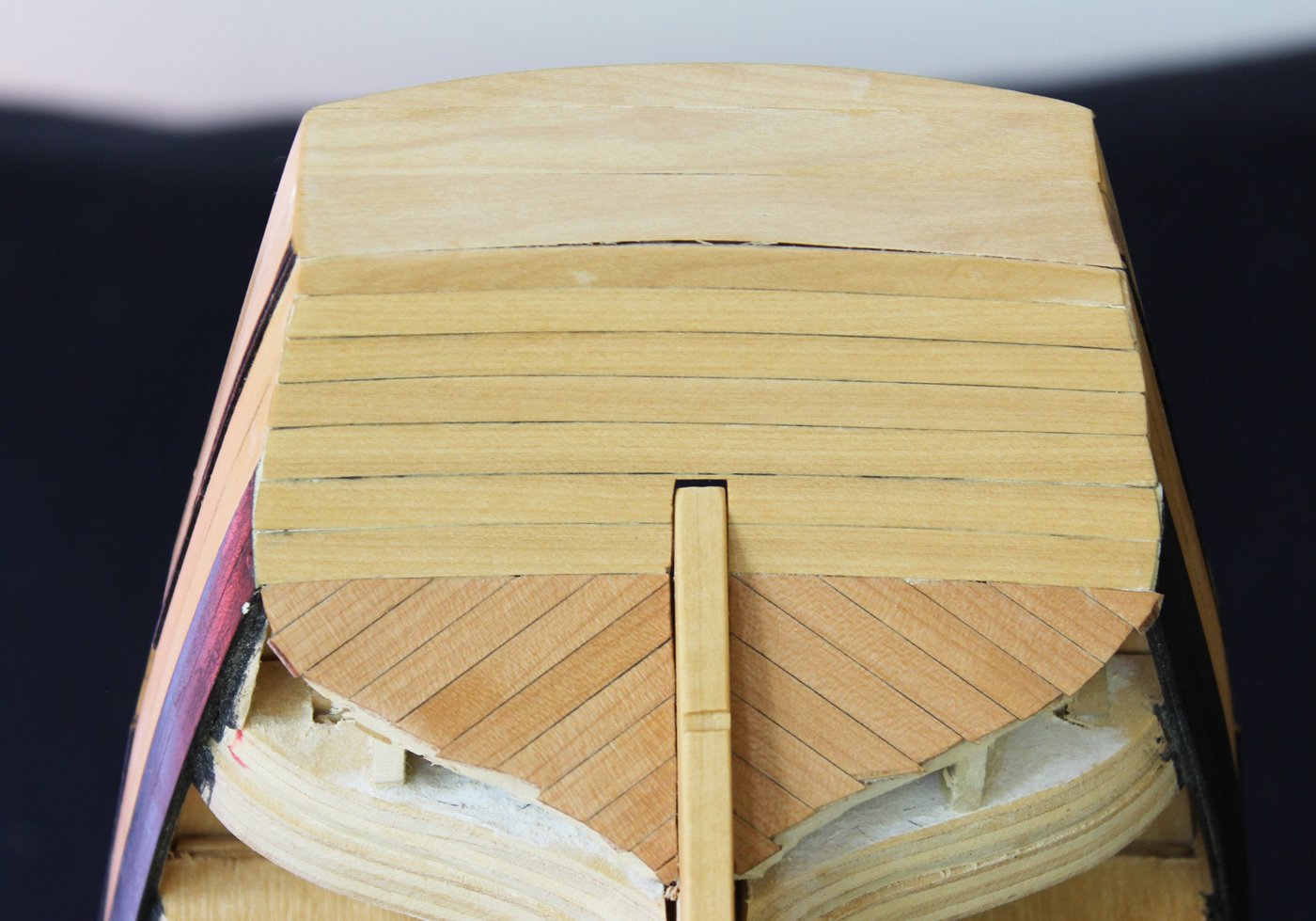
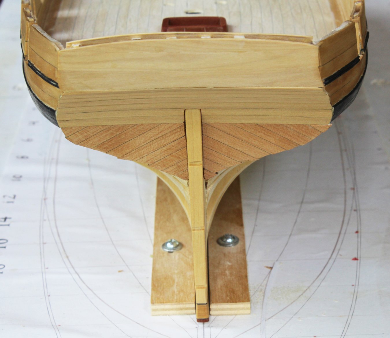
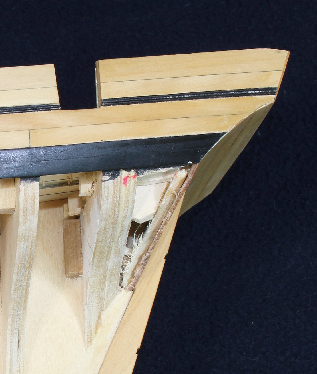
Time to direct attention to the counter and transom. Swallow has a square stern. The model shows these planks installed on the bias. I used pear for these planks as that is what the hull will be planked with. I left them long to allow for notching for the hull's clinker planking. The counter and the transom are planked with costello. Each plank is cut to shape, not edge bent. In the third picture the length of the counter is best appreciated. The transom will have a decorative treatment applied later. It looks different because I chose not to apply a finish to it. The gap between the transom and counter will be covered with a decorative molding. The gap between the sternpost and the stern planking will need to be addressed.


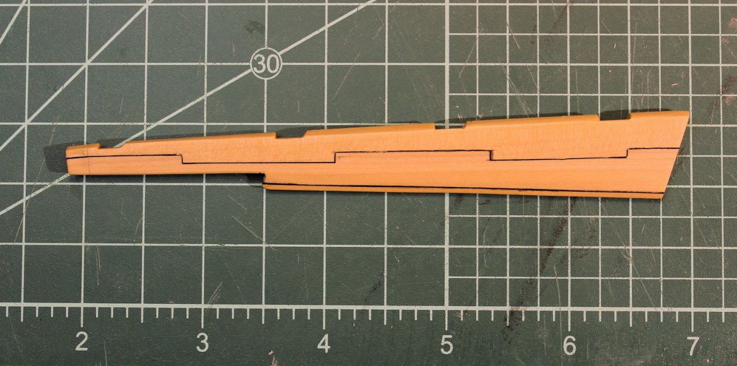
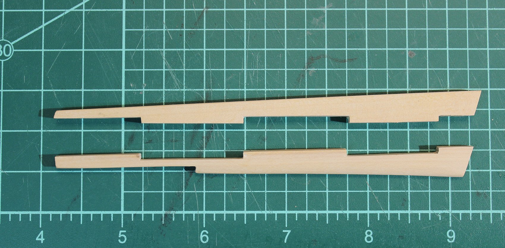
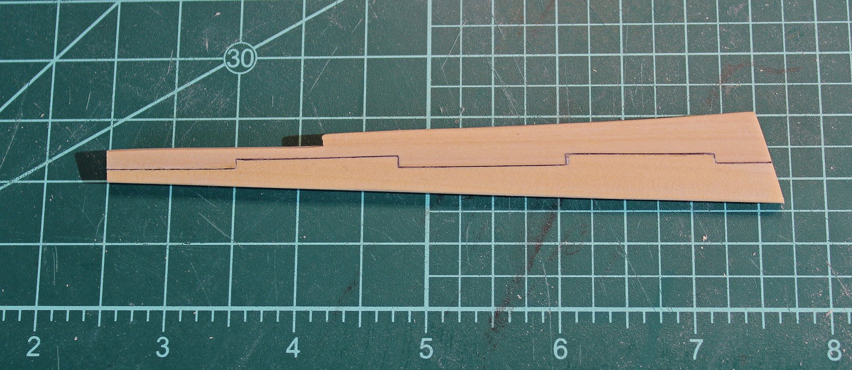
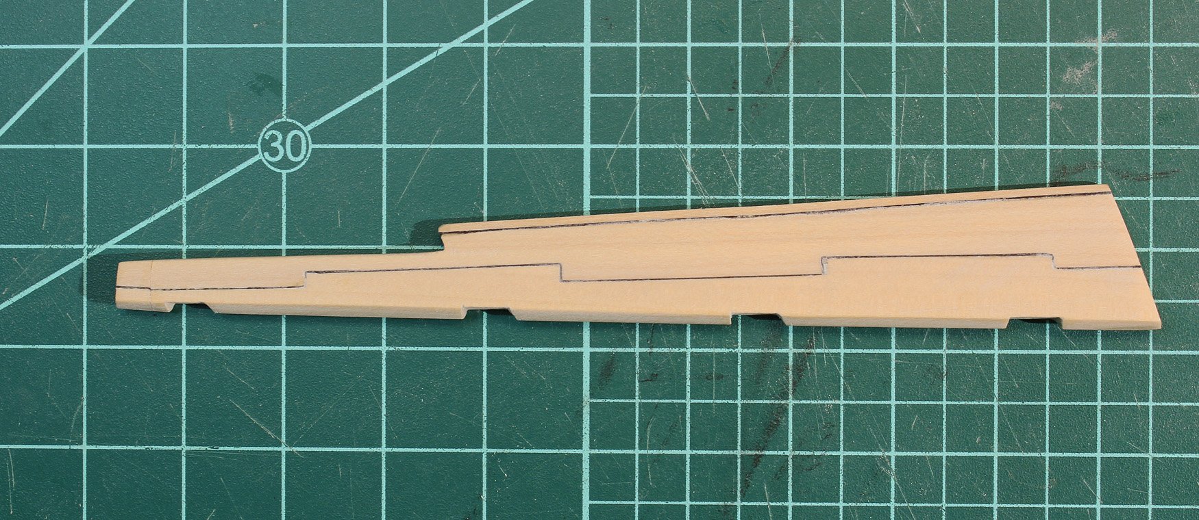
This takes me to the sternpost. As I was planking the stern it suddenly occurred to me that I had not installed the sternpost. This is 13" wide at the top, tapering to 10" at the keel. The aft edge is rounded over and the rebates for the gudgeons are cut in. Since I did not want to remove the aft segment of keel, this was incredibly difficult to maneuver into place. To my horror, the keel was 1/4" too short. My only option was to remove the aft section of the keel and two sections of keelson and replace it with a longer piece. I had not been pleased with the appearance of that section of the keel so this problem was a blessing in disguise. The photo shows the old and new sections for comparison.

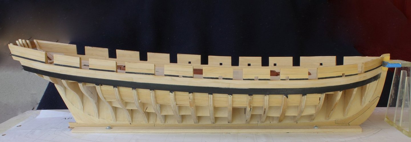
The shim under the keelson is to keep the ship level in the building board as there is a curve in the bow fore and aft. The color difference will decrease after another coat of finish is applied. The bulwarks are still a little high to prevent damage prior to installing the cap rail. My biggest hope is that all of the serious problems are behind me!
- oneslim, garyshipwright, johnp76 and 14 others
-
17
-
It has been a long time since posting any real progress. Sorry, but I would rather be in the garden than in a work room.

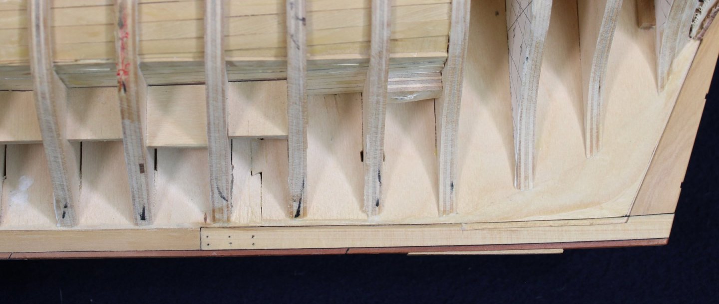
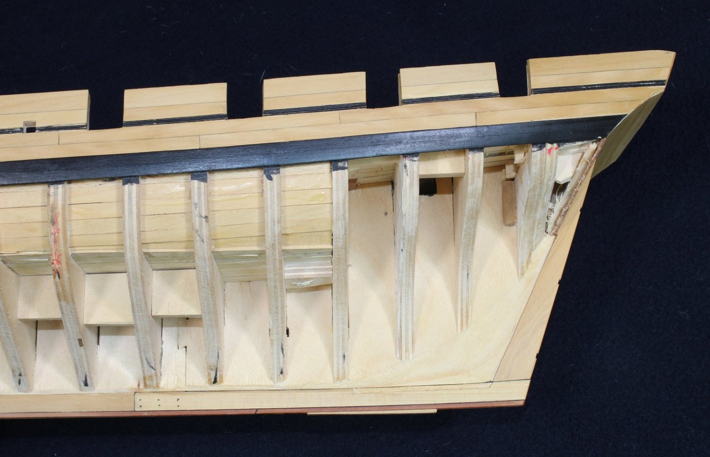
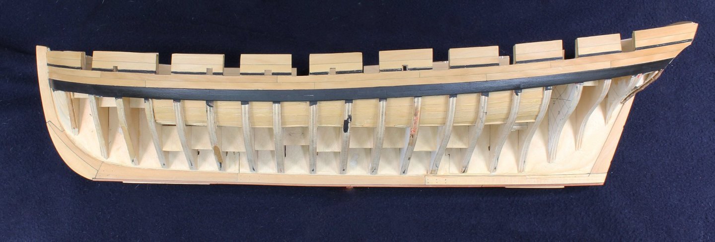
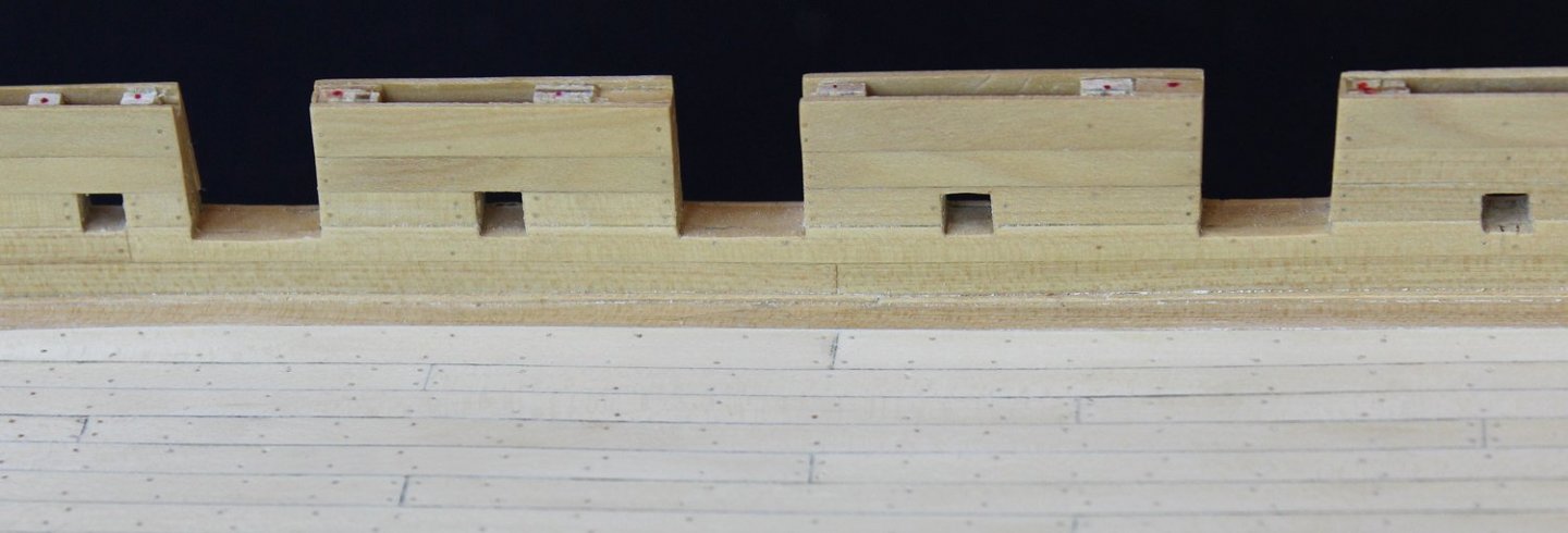
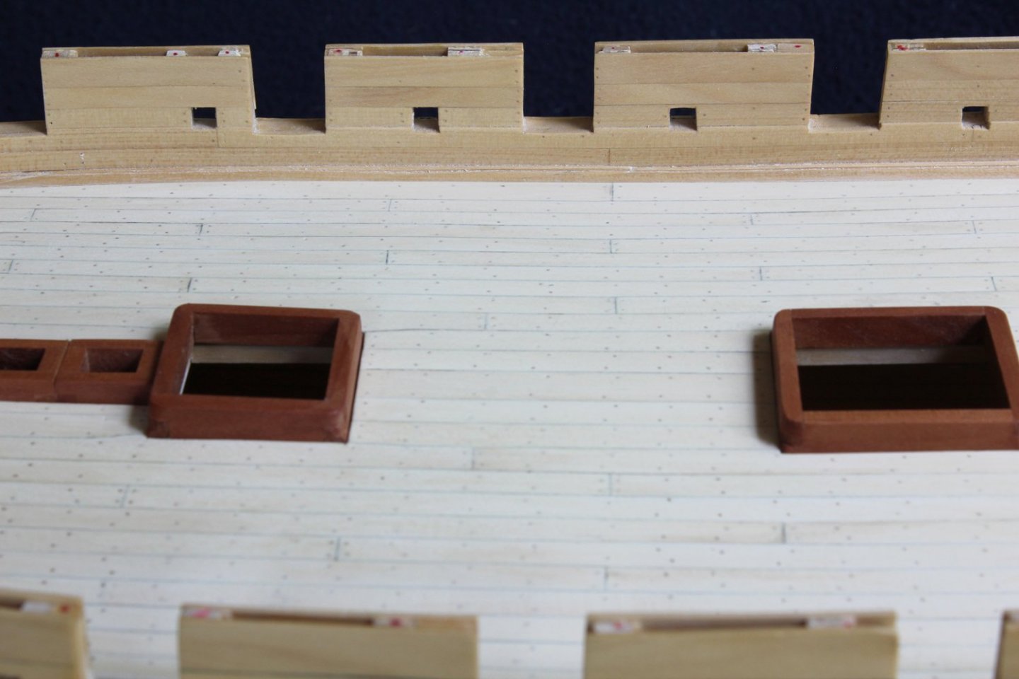
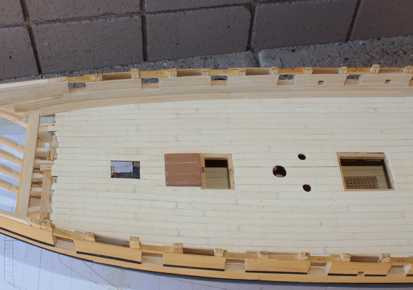
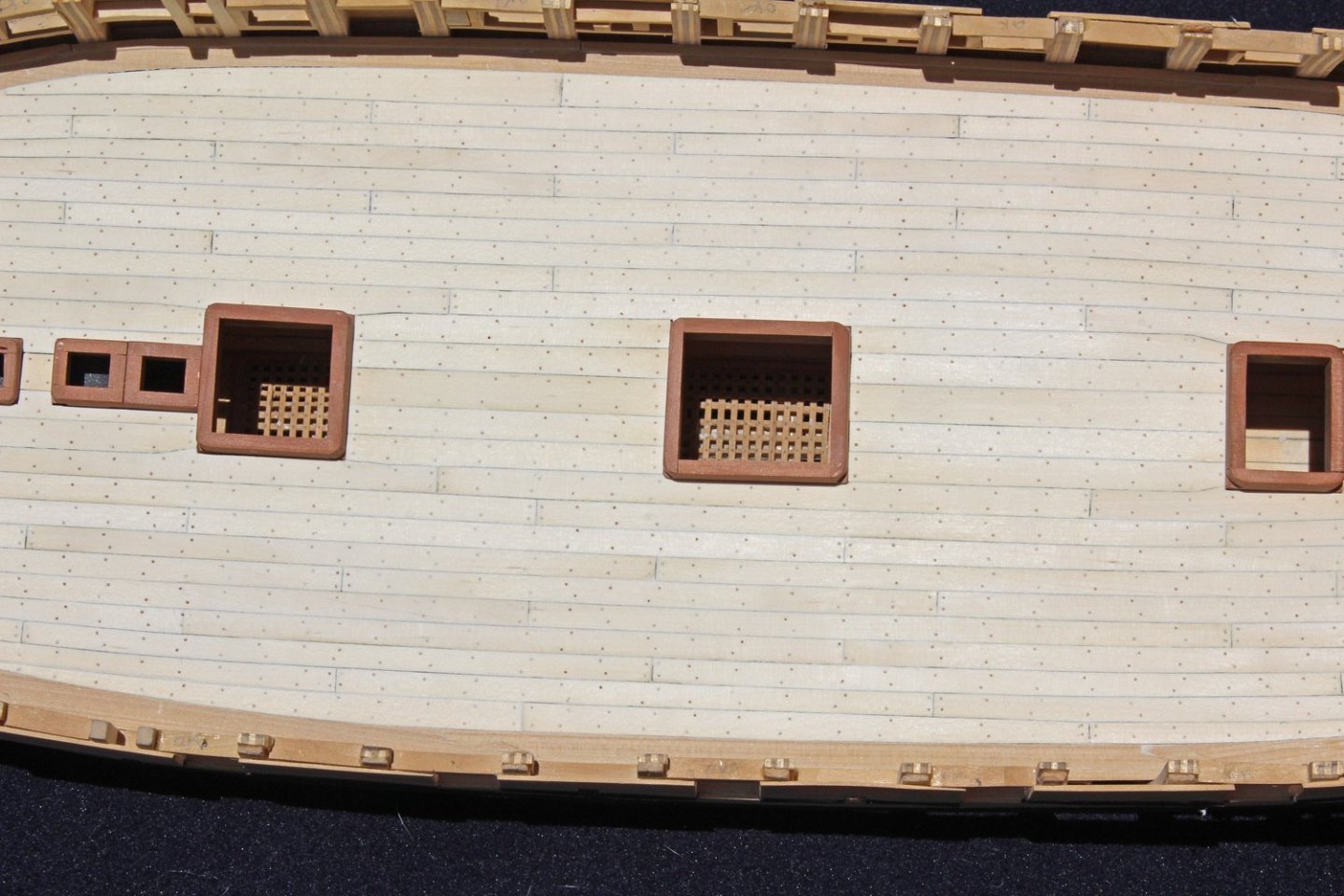
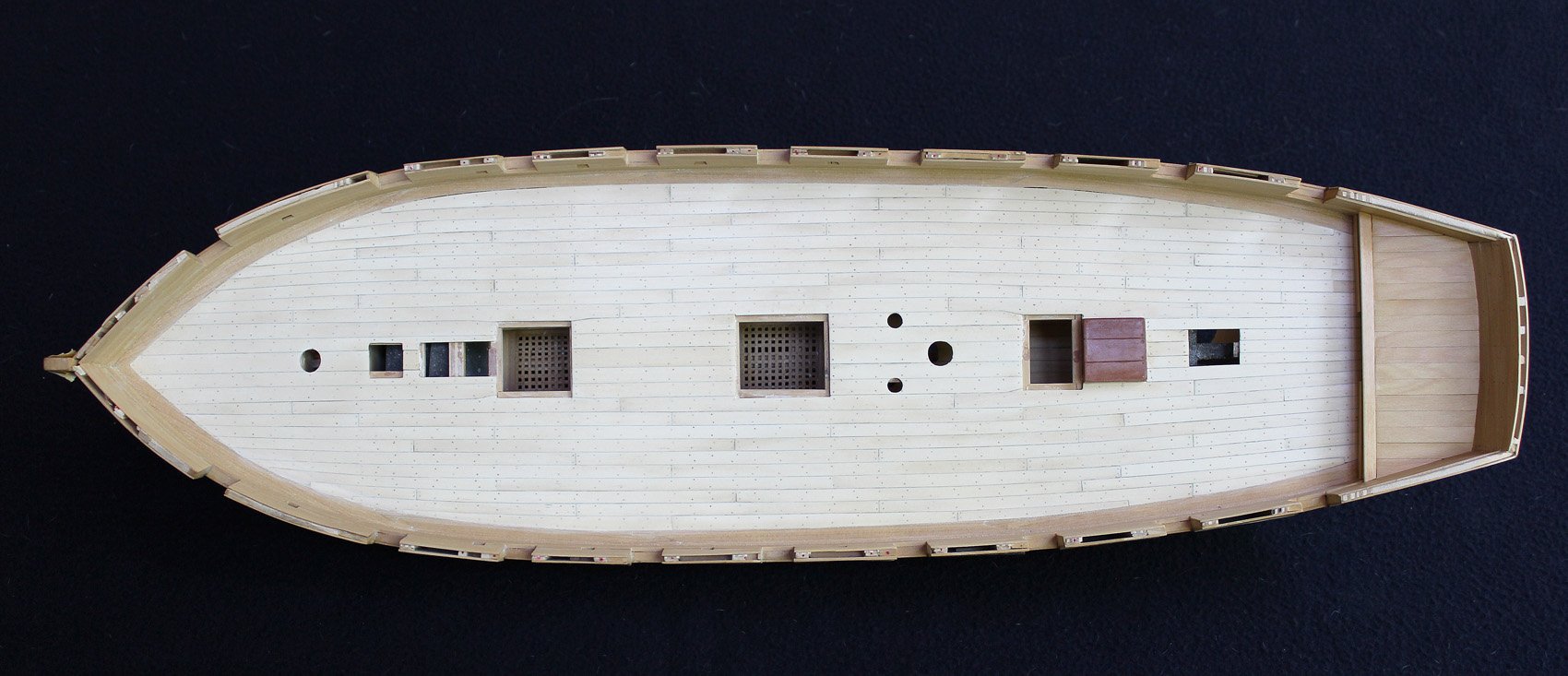
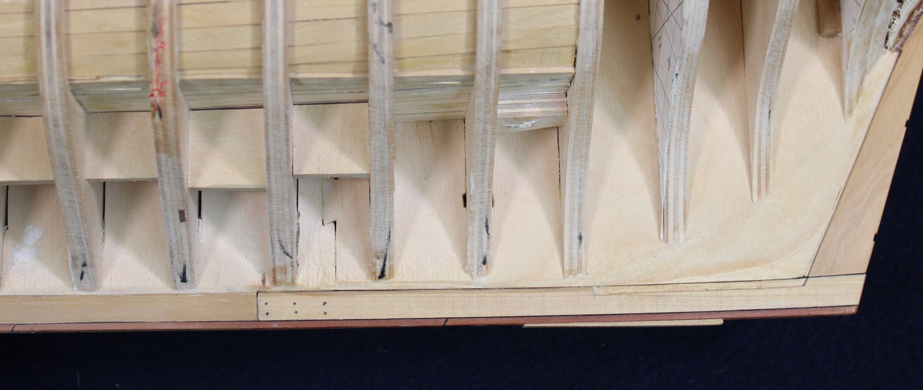
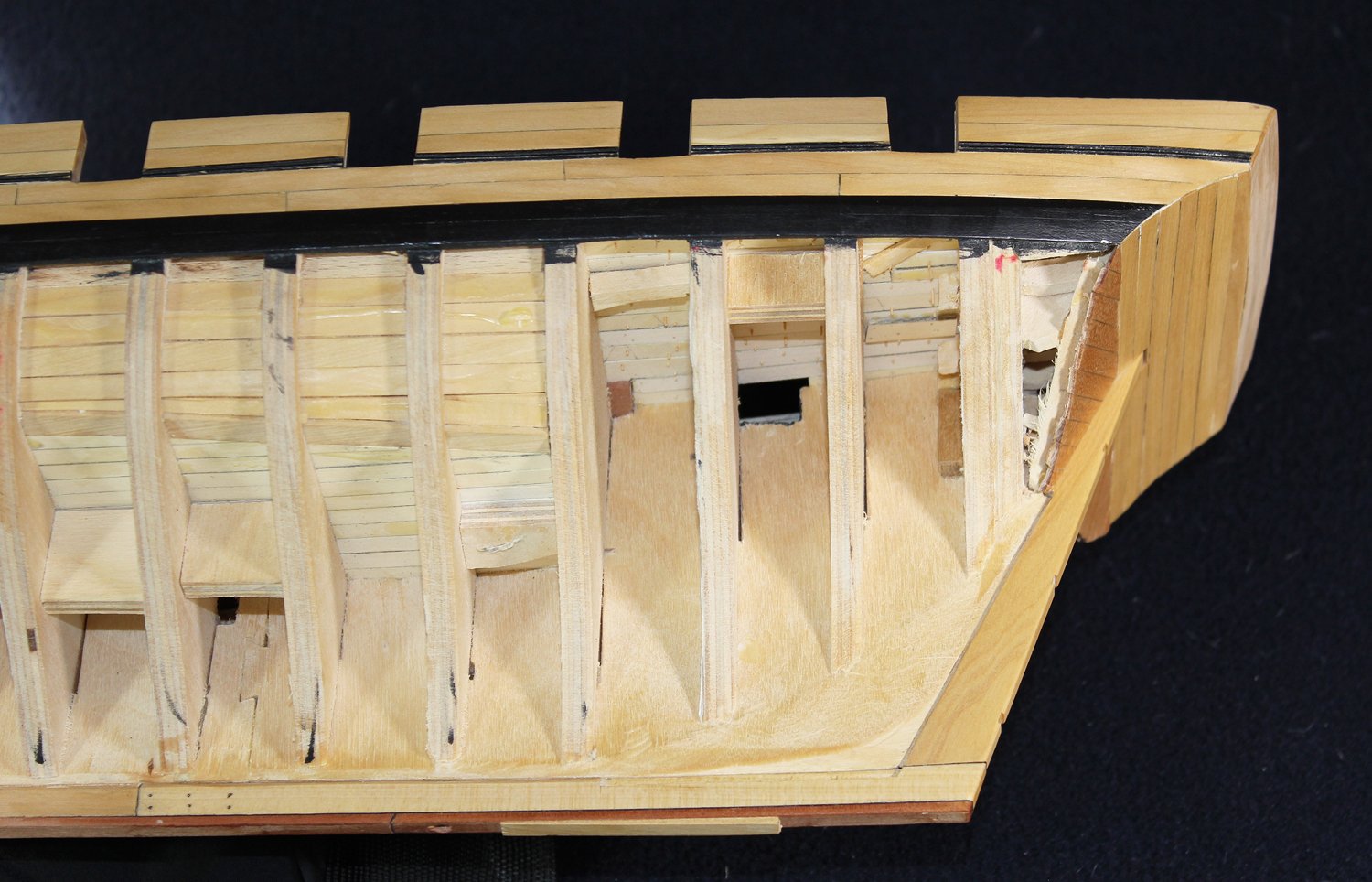
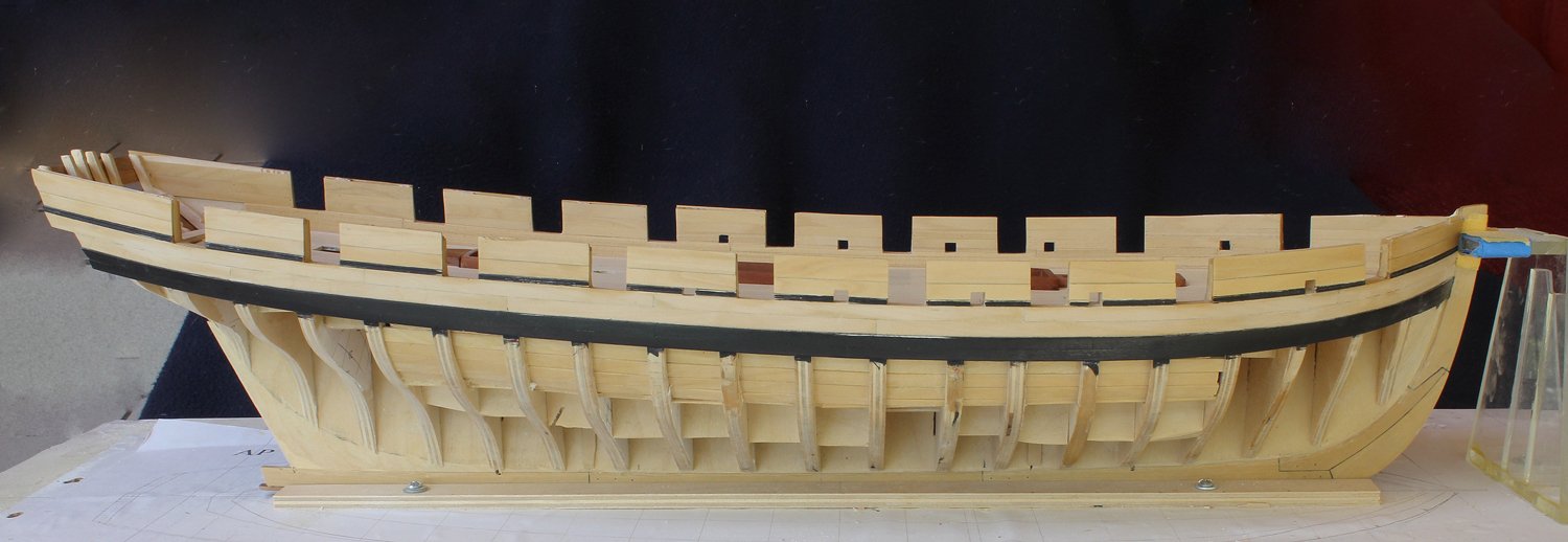
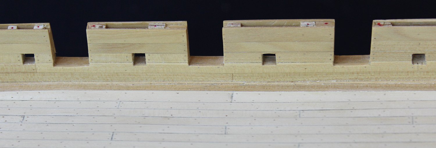
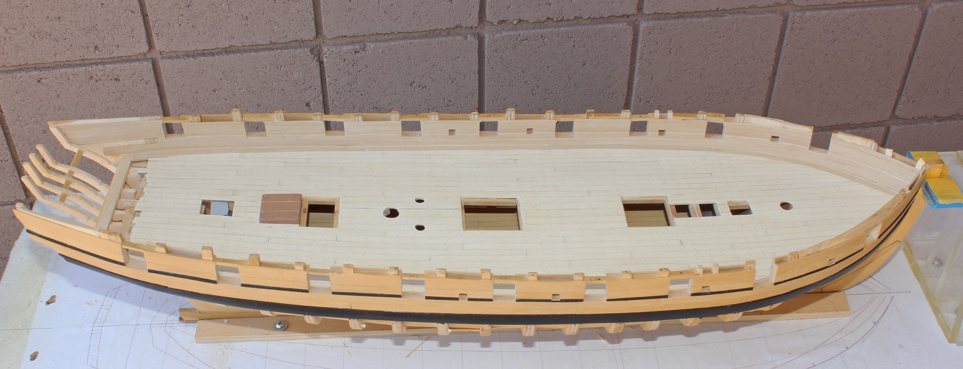
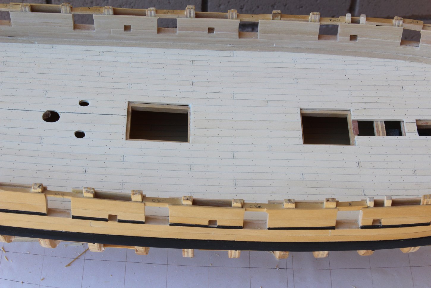
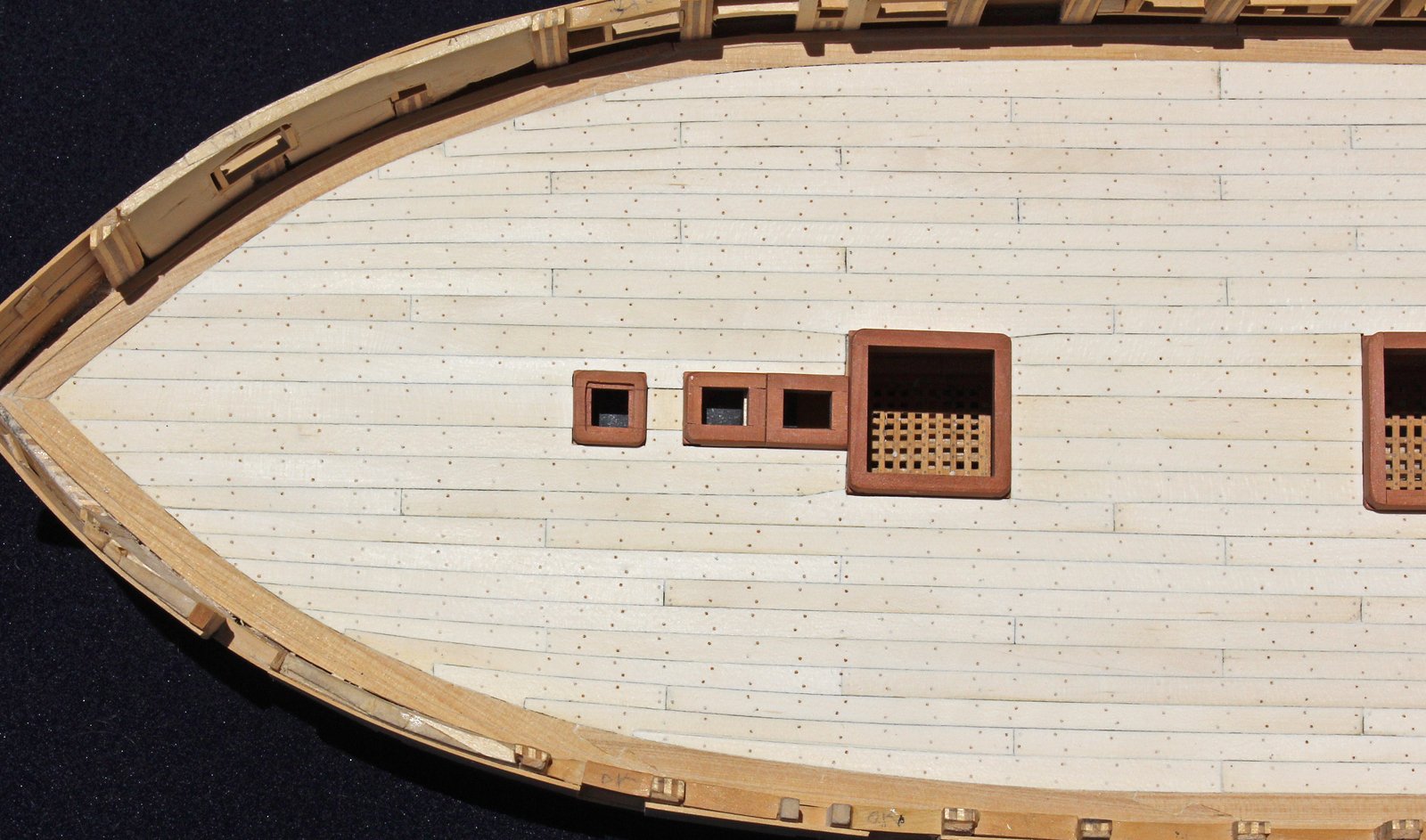
Over the last few months I have found myself replacing most of the inner and outer planking and a portion of the deck. After the outer and inner bulwark planking was finished I realized that the bottom of the oar ports should run in the same line as the bottom of the gun ports. As you can see from the following picture, they did not. So the planking was removed where necessary and the oar ports were framed in the proper location, as seen in the second picture. The paint on the decorative strip looks the worse for wear but this will be touched up towards the end of the build.

I had originally made the thicker part of the inner bulwark planking one row. Further research told me that this should be made two rows wide and therefore, after the inner bulwark planking was rebuilt after repositioning the oar ports, it was necessary to remove it all again to replace the lower row with two rows of planking.
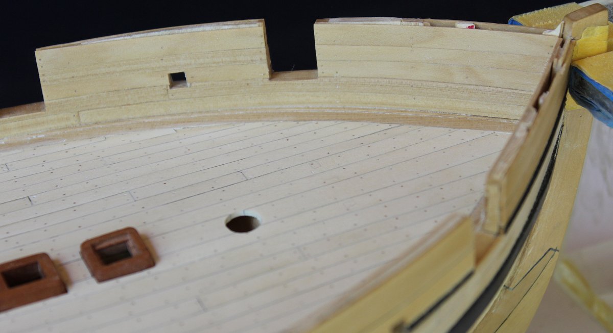
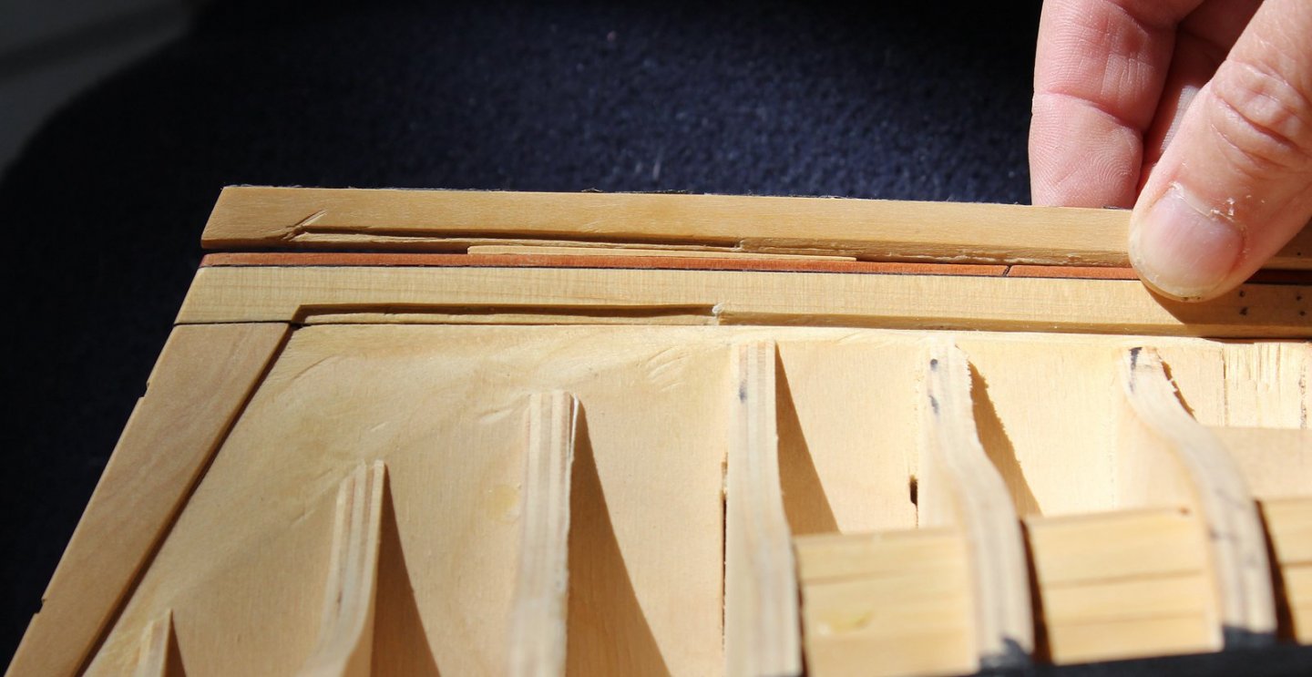
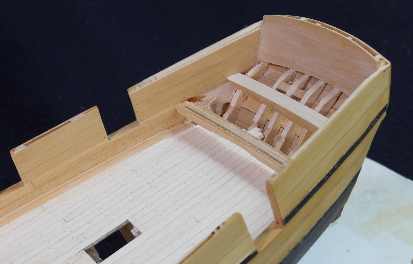
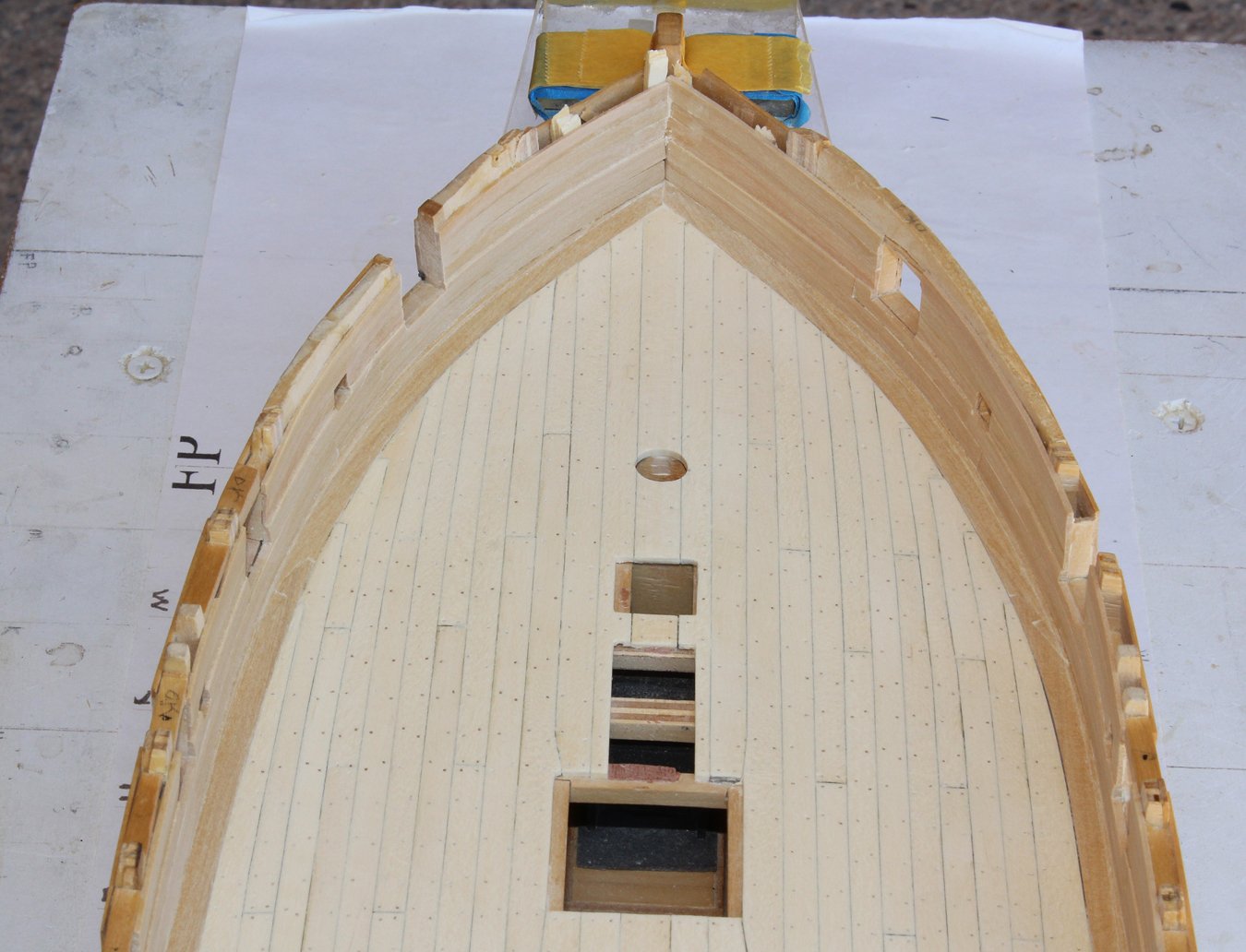
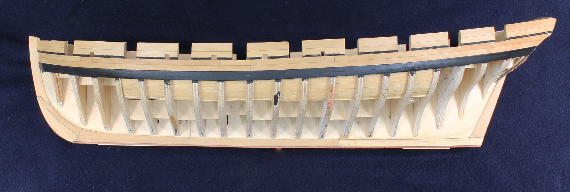
At this point I decided to construct the beams for the aft platform. I discovered that I had misinterpreted the plans. The model shows an aft platform with the tiller coming out from under the platform. The plans, in retrospect, do not show a platform at all and the fore end of the tiller is shown to be almost four feet above the deck. The lines which I thought represented the fore and top of the platform were in fact a decorative molding line and a station line. I will simply say that when I discovered this situation I walked out of the work room and poured myself a stiff drink (maybe two). I had to decide between the model and the plans. So far, whenever there has been a conflict, I have gone with the plans. This time I decided to use the model as my guide. I had planked the deck "knowing" that the platform would extend almost to the last gun port. In examining the model, the platform only extends to a few feet aft of the gun port. Therefore it was necessary to remove and replace all of the decking aft of the capstan platform to compensate for the too-short deck. (Back to that bottle, I'm afraid.) I installed two beams to support the platform planking and planked the transom bulwark. I was very lucky to match the color of the old and new decking. The first picture shows the end of the planking initially. The others are after the deck was elongated. The notch on the bottom of the front beam is for the sweep of the tiller.


-
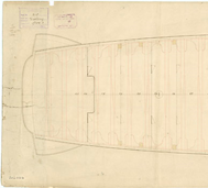
I am a little late to respond but I would suggest going to the National Maritime Museum website and look up the plans for Victory so you can see the correct curvature. This is an excerpt from https://collections.rmg.co.uk/collections/objects/79917.html which shows the stern curve.
-
Very nice job. That linseed oil makes the basswood glow. Thanks for sharing.
- bruce d and Overworked724
-
2
-
-
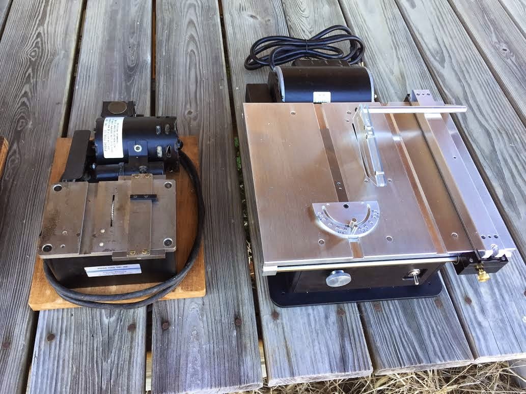
Well, I am thrilled that you chose Swallow for your first post. You picked up on my bad typing skills; it should have been 0.021" I use BBQ skewers and saw them into quarters on a Preac saw with a 0.016" slitting blade. I then pull these through a Byrnes drawplate. Since you are new to the hobby, the Preac is a small table saw which is no longer made. I use it for fine work rather than a Byrnes saw. Less likely to cut my fingers off! This is a picture comparing the two saws that was taken from Mini Sourthern Millworks December 2014 blog.
- Roger Pellett, mtaylor, druxey and 5 others
-
8
-
-
Please take a look at both Chuck's and David Antscherl's tutorials on planking. Although they do not exactly fit your situation, you will learn why you are in trouble. These are located in the Articles Database seen at the top of the page. Even though you are not spiling the planks (custom shaping each plank to conform to the shape of the hull), you still need to divide the hull into "belts" containing 4-5 rows of planks. It should be obvious that the planks at the bow are more narrow than the ones amidship and the ones at the stern are wider. The change in width from fore to aft will be different in each of the planking belts. The planks at the bow will need to be tapered and you may need to use a "drop plank". At the stern you will need to add a "stealer".
Don't fall into the trap of "this is the first layer of planking and no one will see it". This is your opportunity to see how the run of planking should go so that the second layer is perfect.
-
-
-
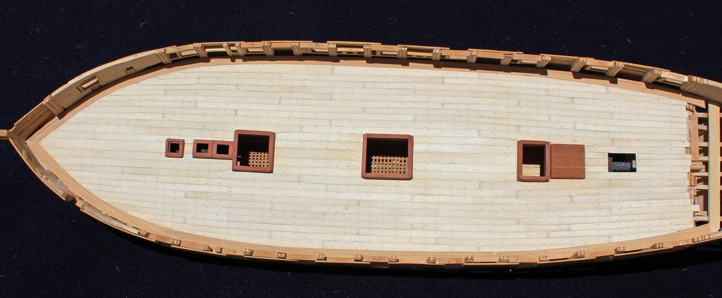
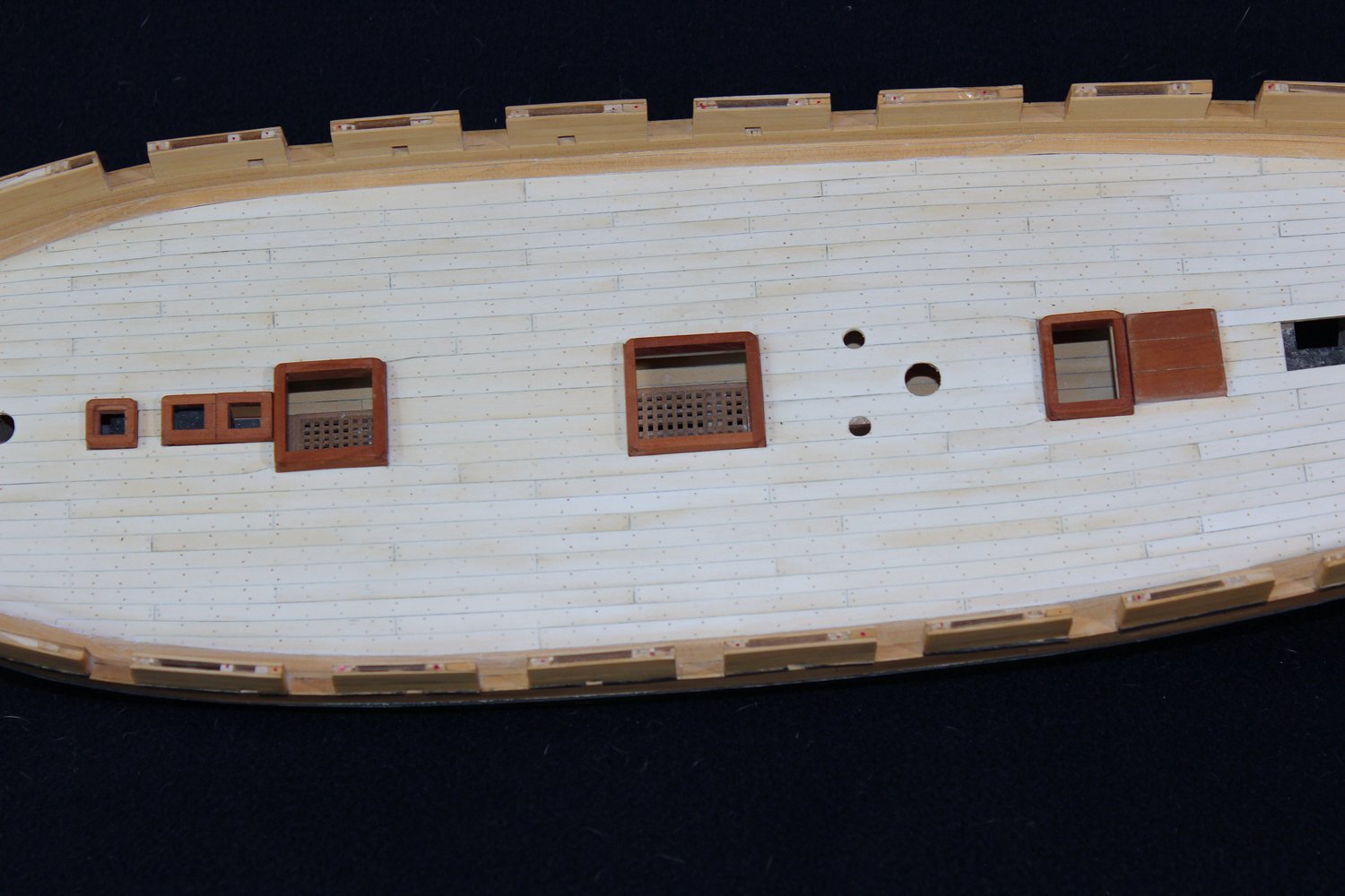
JD, the only plans I have are the plans from the RMG. These would not typically show a planking layout for either the hull or the deck. In this era, planks were not joggled into the waterway, they way they are on later vessels. The basic rule is not to allow any plank to narrow by more than 50%. At the bow and stern, that is accomplished with dropped planks (there is one on either side on this deck) and nibbed plank ends (four fore and two aft). I could have also laid the deck with an additional dropped plank and fewer nibbed planks. My biggest problem was that the outermost plank is too wide on the starboard side amidships. As that will be camouflaged by a cannon, I am not going to risk damaging the rest of the deck and waterway by removing it. I hope that answers your question.
-
-
I have finished planking the inner bulwarks. The lower two rows (spirketting) are 3" thick and the three upper rows (quickwork) are 2" thick. Referring to TFFM, the Swan class spirketting was installed top and butt. As Swallow was a purchased ship and not necessarily made to RN establishments, I chose simple butt planking instead. The port openings still need a little work in these photos. At this point I am torn between finishing the bulwarks with a clear matte finish or paint them. The model from the RMG shows a clear finish except on the transom, which is red. However, it also shows gold leaf on the outer edge of the channels! If I decide to paint the bulwarks, I will not bother with treenails.
I will be taking a week off for some real life issues; this will give me time to think about the options.


-
-
-
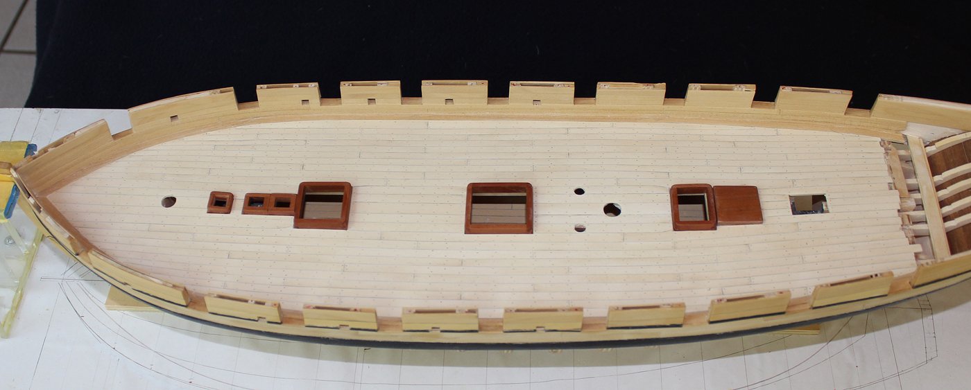
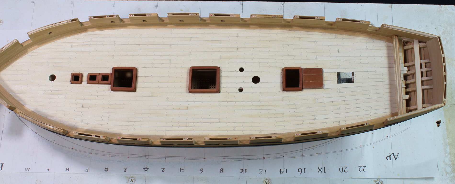
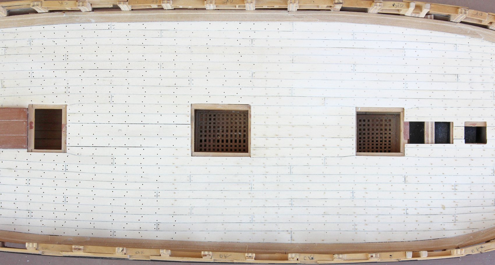
Just a quick update. The deck has been trunneled and sanded. The trunnels were made from bamboo obtained from barbecue skewers. They were drawn down to #75 drill bit (0.21") or 1" in full size. Bamboo was selected because of its subtle effect with the holly decking. I would have preferred a slightly smaller trunnel, #76 or #77, but my bamboo was too brittle to draw that thin. And with COVID-19, I simply was not in the mood to shop for another package. I would be hard pressed to call that an "essential" purchase. Trunnels are secured to the beams and the ledges. I went back to the plan and marked the beam locations on the deck. Then I drew in the presumed locations of the ledges, typically two ledges between each beam. The picture shows the deck with the trunnels drawn in and dimpled with a fine awl (aft), with the holes bored (between the ladder way and the main hatch), trunnels inserted but not sanded (starboard bow) and finally, sanded down (port side between the two hatches). The effect is subtle but will be a little more prominent once a finish has been applied. I still have not decided whether to simply apply a sanding sealer which will help maintain the white color or tung oil which will yellow the planking.
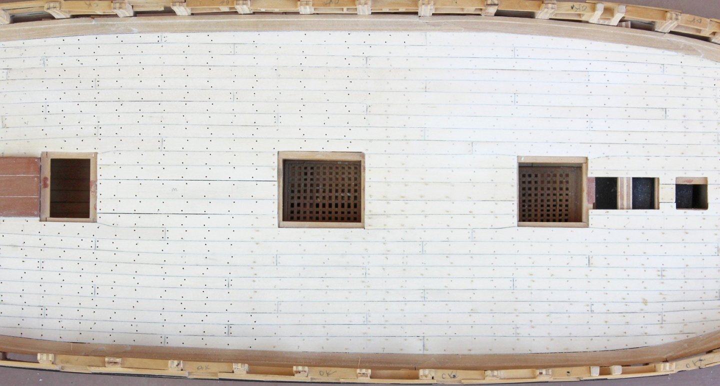
I use a needle holder to grasp the trunnel as I insert it. I do not use any glue. There is a tight friction fit and the finish will secure them. The inner bulwark planking is next.


Swallow 1779 by tlevine - FINISHED - 1:48 scale
in - Build logs for subjects built 1751 - 1800
Posted
Then again, some people really like catfish!