

tlevine
-
Posts
1,944 -
Joined
-
Last visited
Content Type
Profiles
Forums
Gallery
Events
Posts posted by tlevine
-
-
Drill Bits Unlimited and Drillbit City sell essentially the same bits. If you have a tremor, stick with HSS bits unless you are using a drill press. Using a carbide bit in a Dremel is not a problem as long as you Have a steady hand and do not put any lateral pressure on the bit. I would never put a carbide bit in a pinvise.
-
-
I cannot believe it has been over three months since I posted on Swallow. I promise you, I have been busy on her and a few other things. Take a peek at the Capstan Project. Also, I was unhappy with the appearance of the upper planking. It has all been removed and rebuilt. Trunneling has started and pictures will be forthcoming soon.
-
The first thing any builder should do is read the entire instruction set for both intermediate and advanced and look at the plans. This will help in two ways, first you will be less likely to make stupid mistakes. Secondly, you may want to build one part from the intermediate and another from the advanced project (for example, you own a lathe but not a mill and want to build the advanced barrel but the intermediate drumhead). Make sure you understand the plans. Most of us are not used to looking at engineered drawings; kits typically include perspective or distorted drawings to prevent copying. Decide on your scale, develop a materials list and gather your lumber. If you are using contrasting species of wood, buy a lot more than you think you need. I had to change species for my advanced hatch coaming because I ran short and could not color match replacement wood. Except for the capstan barrel, do not attempt to build this with soft woods. Now to get started.
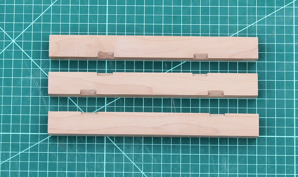
The individual subassemblies (deck, barrel, drum head, hatch and grating) can be built in any order; they are assembled as the last step. I started with the deck. There are three beams and two carlings between each beam. The carlings support the capstan step and the hatch. For simplicity, the mortices in the beams are cut at an angle. This is readily accomplished with a razor saw to make the cuts and an 11-blade to remove the wood between them. Once the carlings are installed, no one will know you "cheated".
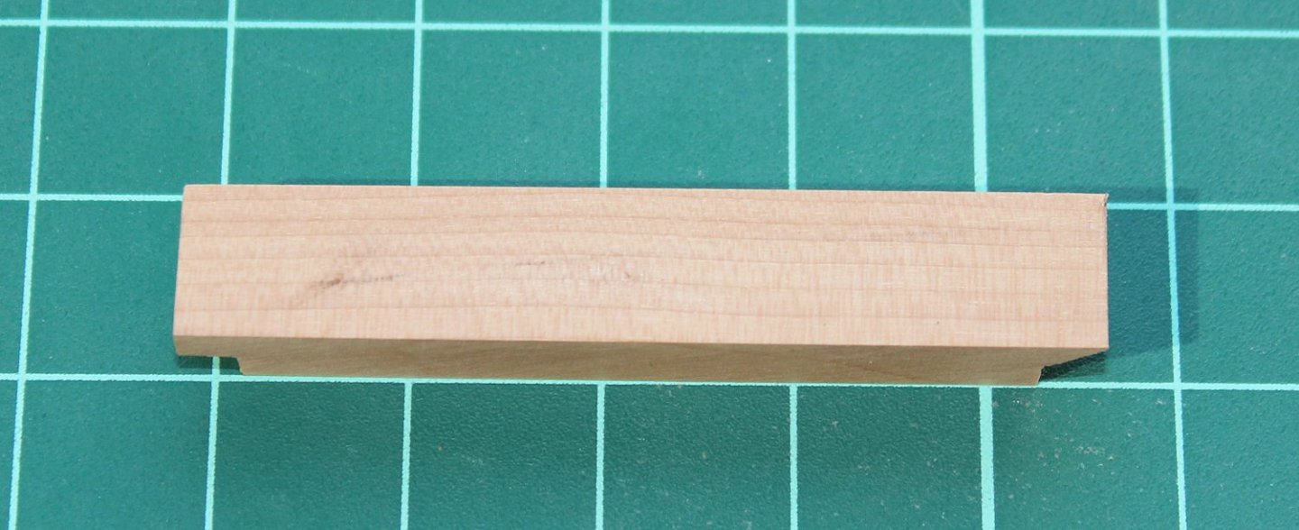
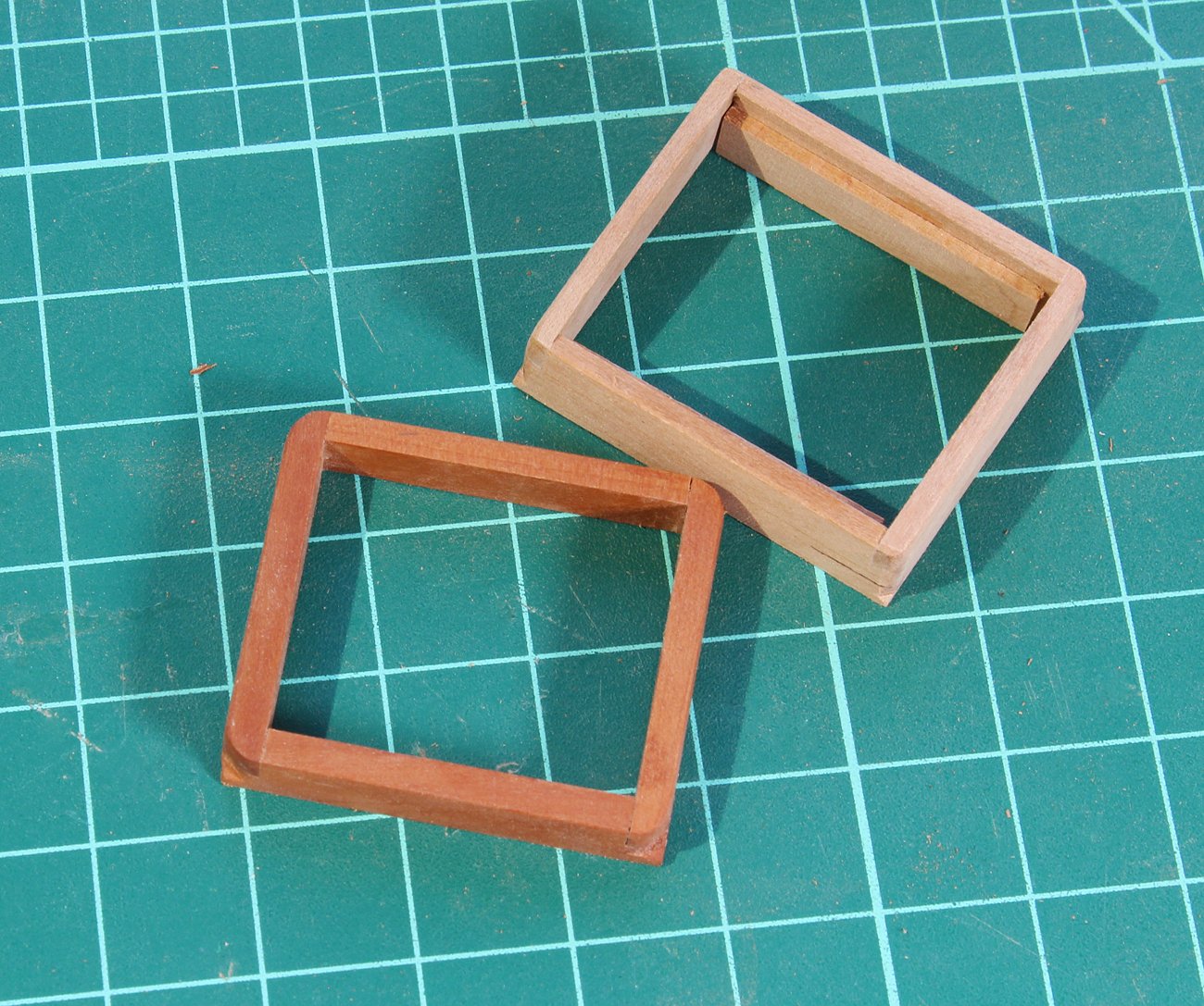
The carlings are next. Again, the tenon has been simplified. On the right, you can see the simplified tenon and on the left a proper one. Looking from above, there is no difference.

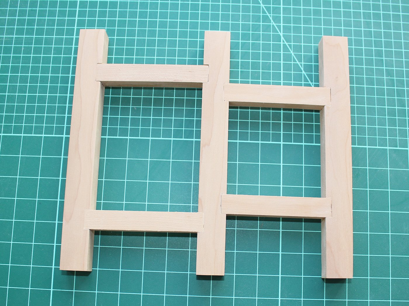
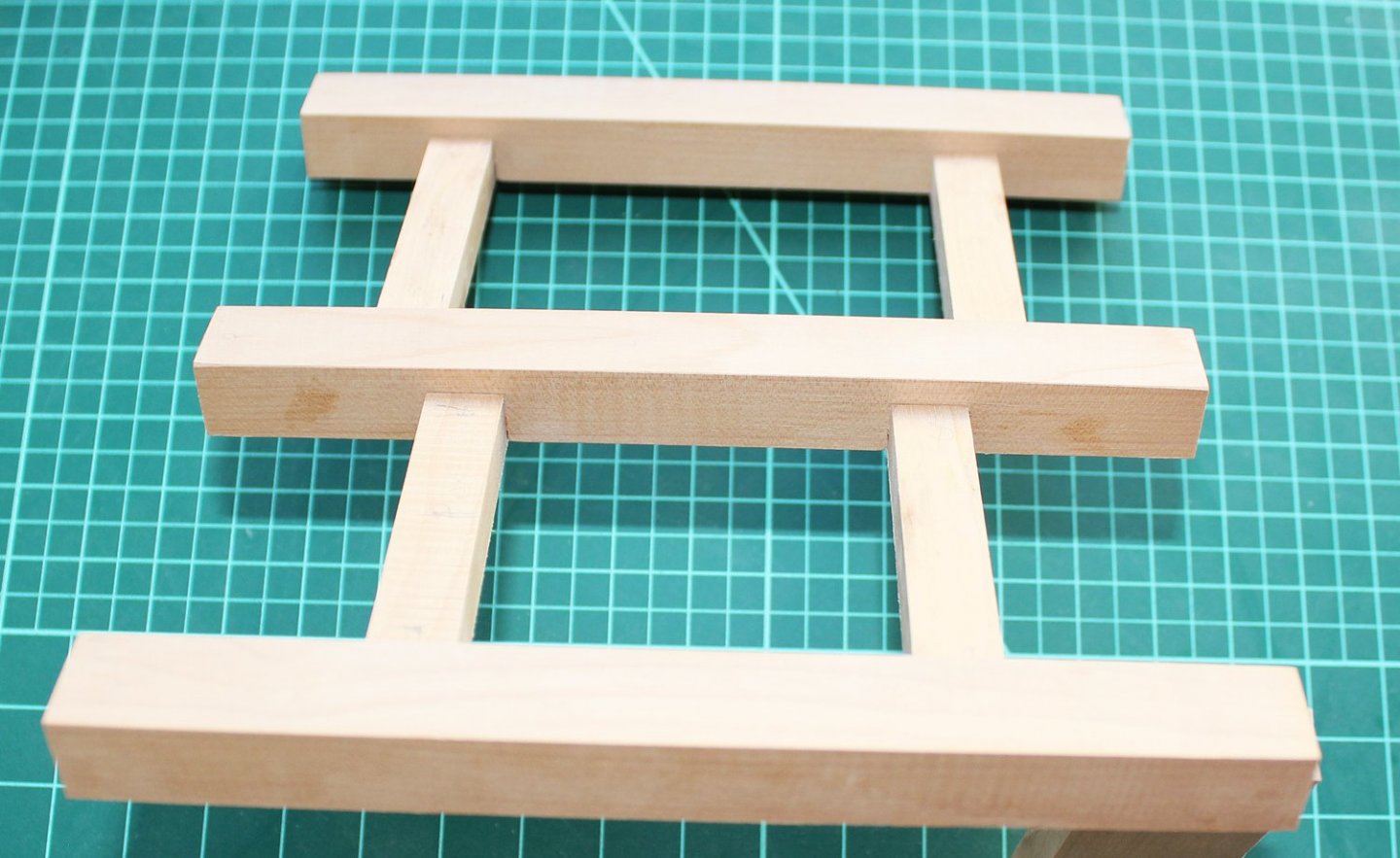
And here is how it looks with the beams and carlings assembled. Make sure everything is square.
-
Two years ago, the Guild started selling the half hull kit, a project designed to include modelers who had no access to power tools. The purpose of the kit was to teach modelers how to plank a hull by spiling. The Guild has a new project, actually two projects, designed to expand your modeling skills and develop confidence in the step towards scratch building. As you know, the Guild’s logo is a capstan. Our next project is construction of a capstan, shown on its step, with a hatch and grating. The first project is designed for the builder whose only power tools are a Dremel-type rotary tool and a hobby circular saw. The second is for the builder who has all the “toys”, including a lathe and mill. This is a picture of the completed intermediate-level capstan.
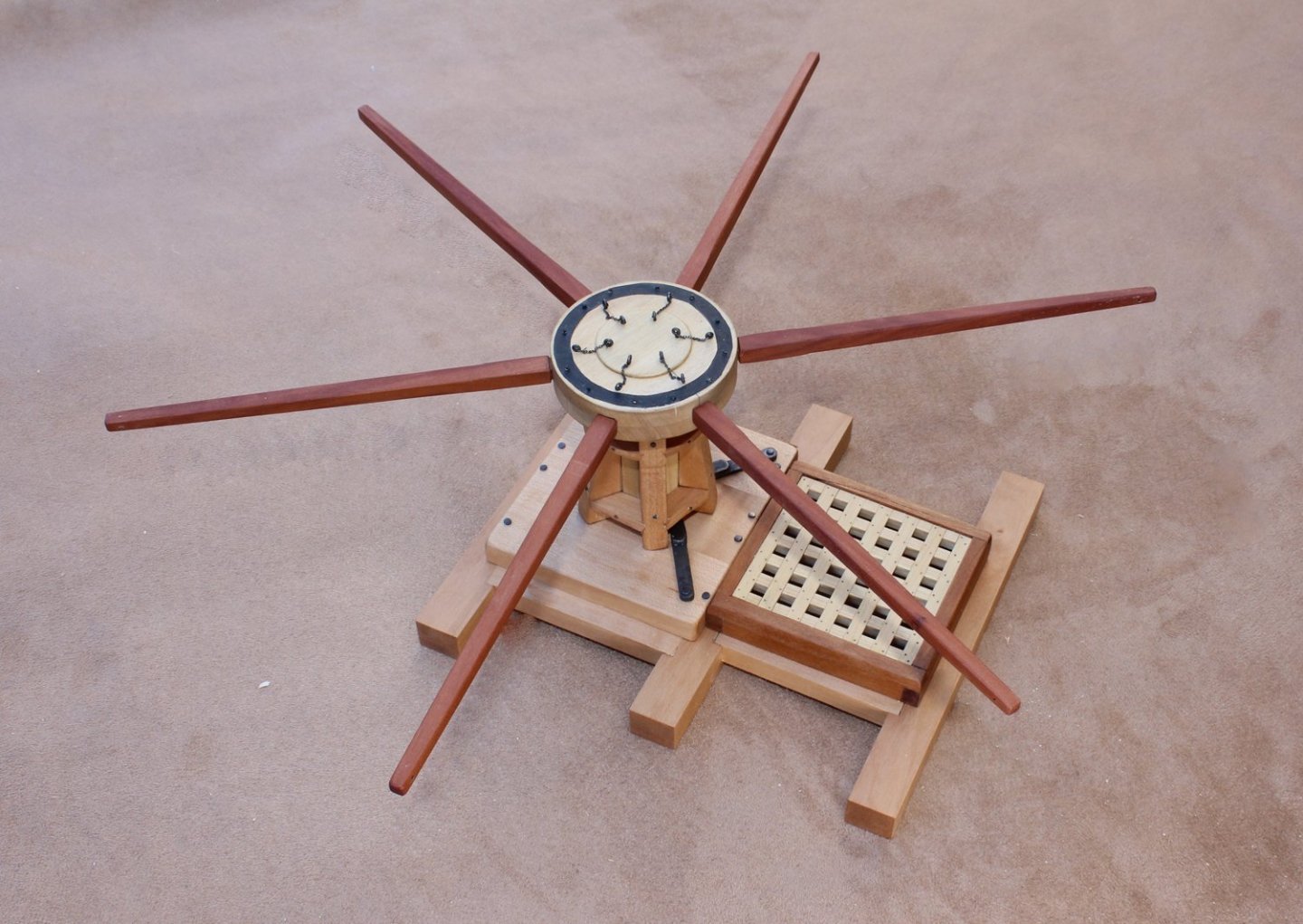
Because this is an introduction to scratch building, the project will be sold as a download which will include a monograph and fully dimensioned plans for both the intermediate and advanced projects. No wood is included. The builder will choose the scale of construction and develop their own lumber list. Most of the plans are drawn at a scale of 1:16 (3/4 scale). At this scale, the completed model measures approximately 6” x 6” without the capstan bars and 12” x 12” with them installed.
Let’s get started…
-
Lester, I removed your email address for your safety. If anyone can help him, please send him a PM.
- mtaylor and Ryland Craze
-
 2
2
-
19 hours ago, Keith Black said:
Greg, I'm sure most of us could scrounge at least four from the wasteland perimeter.
Another advantage to being a girl! 👸
- Wintergreen, FriedClams, mtaylor and 5 others
-
6
-
 2
2
-
The cheapest price I could find was here: https://www.micro-tools.com/products/mp $5.95. Much less than Micro Mark.
- thibaultron, Canute, RichardG and 1 other
-
4
-
A few minutes in the oven (250F) melts the wax into the rope. Loosely loop it on a paper towel that has been placed on a pre-heated sheet pan.
- bruce d, thibaultron, Chuck Seiler and 3 others
-
5
-
 1
1
-
-
-
Wow! No other words are necessary.
- Keith Black, dvm27, mtaylor and 3 others
-
6
-
-
The key is to treat the copper before it is on the hull, not after. Things to consider... Are you using copper tape or individual plates? What was the original intention of the product, i.e. is there a protective finish that needs to be removed before the "weathering" can occur? What is the look you are after? At launch, just pulled out of the water before cleaning and in a drydock after cleaning and repair will all look different.
-
I bought some 2 mm chisels from the Carving Glove Guy a few years ago. I already had 3 mm "original" Dockyard chisels that are probably 25 years old. The physical appearance is identical and their cutting and sharpening characteristics are also the same. The sharpening set is also a great help for the V and U chisels.
- Canute, Roger Pellett and mtaylor
-
3
-
Great talk! And thank you for mentioning the NRG and MSW.
- Cathead, thibaultron and mtaylor
-
3
-
I am very sorry about the problems you have had. The warpage should not cause any problem with the bulkhead assembly or plank installation. Drop me a PM if something is not coming together right.
-
-
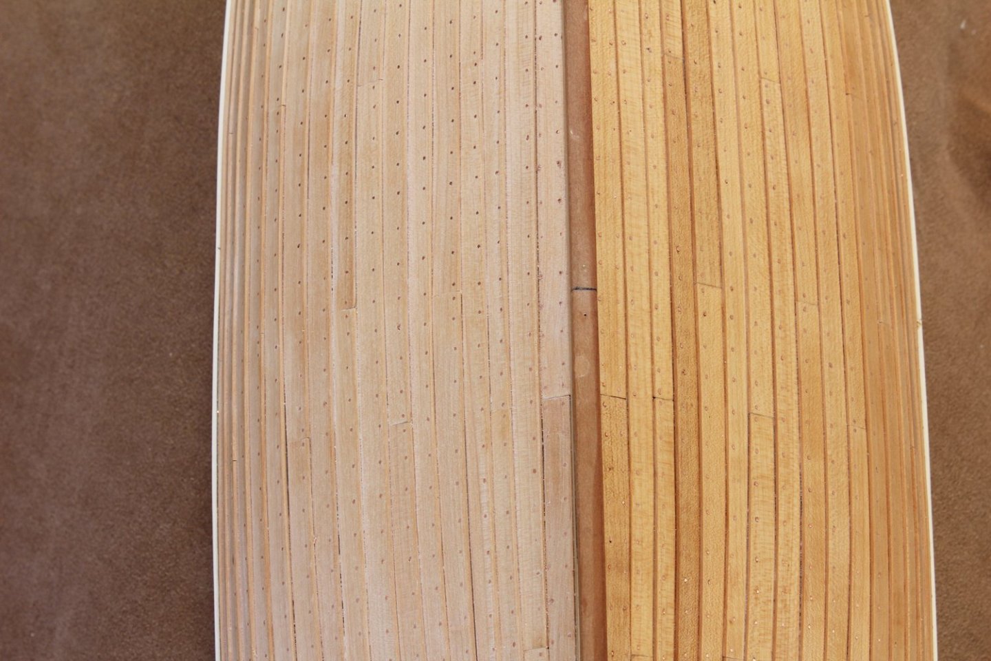
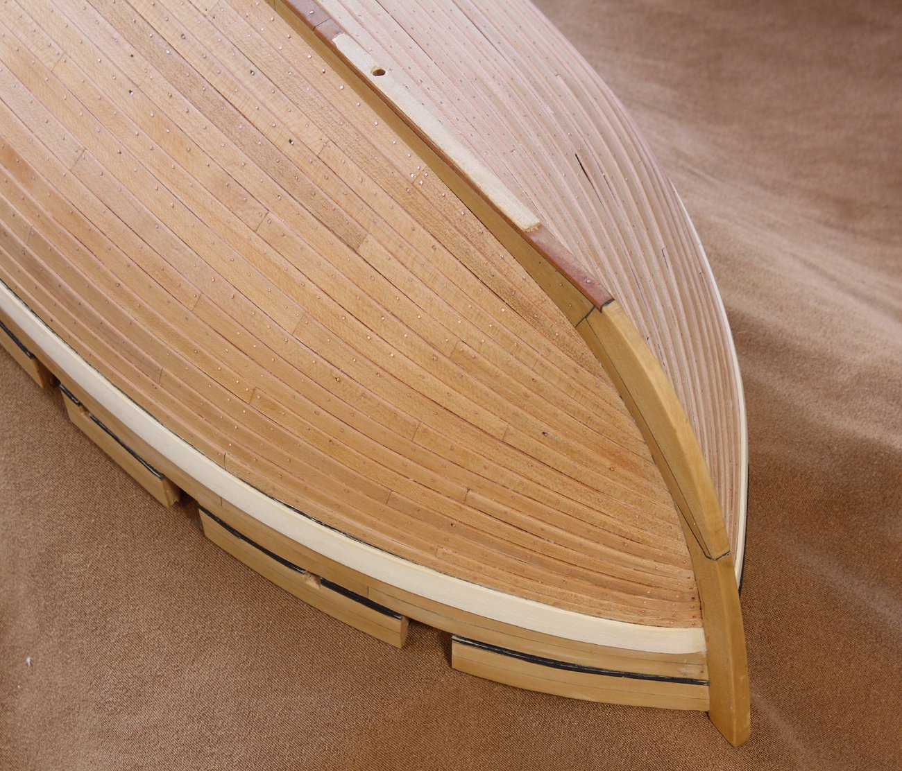
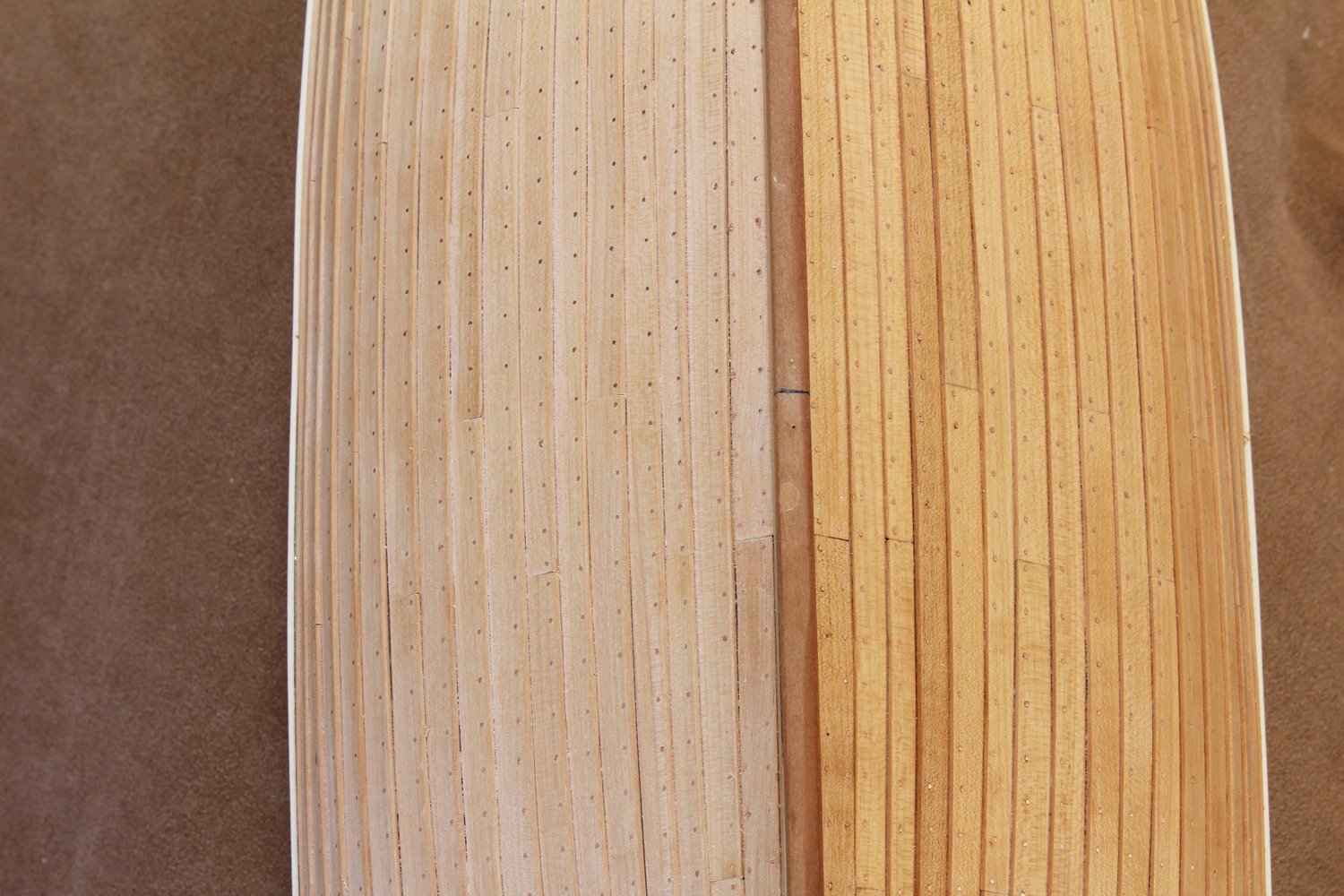
The coppering on the starboard side is now finished. You can see the difference between the port side with a finish applied and the starboard with none. I have decided to delay applying the finish until the wale has been redone.

While doing research for another project, I discovered that the coamings were built several inches too short (8 inches instead of 13). You can see the difference in the picture below. Time to rebuild them all.

- GrandpaPhil, Siggi52, bruce d and 21 others
-
24
-
If I am drilling holes smaller than #75, I want that hole to be the correct diameter and with a crisp outline. Most of the smaller drill bits placed in a Dremel with a micro chuck or Proxxon have some "shimmy", resulting in oversized holes. For this reason, I almost exclusively use resharpened carbide drill bits for the smaller sizes. I have been using Drill Bit City https://drillcity.stores.yahoo.net/ for years. They are located in the Chicago area.
-
-
If Toni starts forgetting stuff she's got some serious issues!
- Canute, Nirvana, Overworked724 and 1 other
-
4
-
Sorry for the late reply. I posted yesterday but for some reason it did not "take".
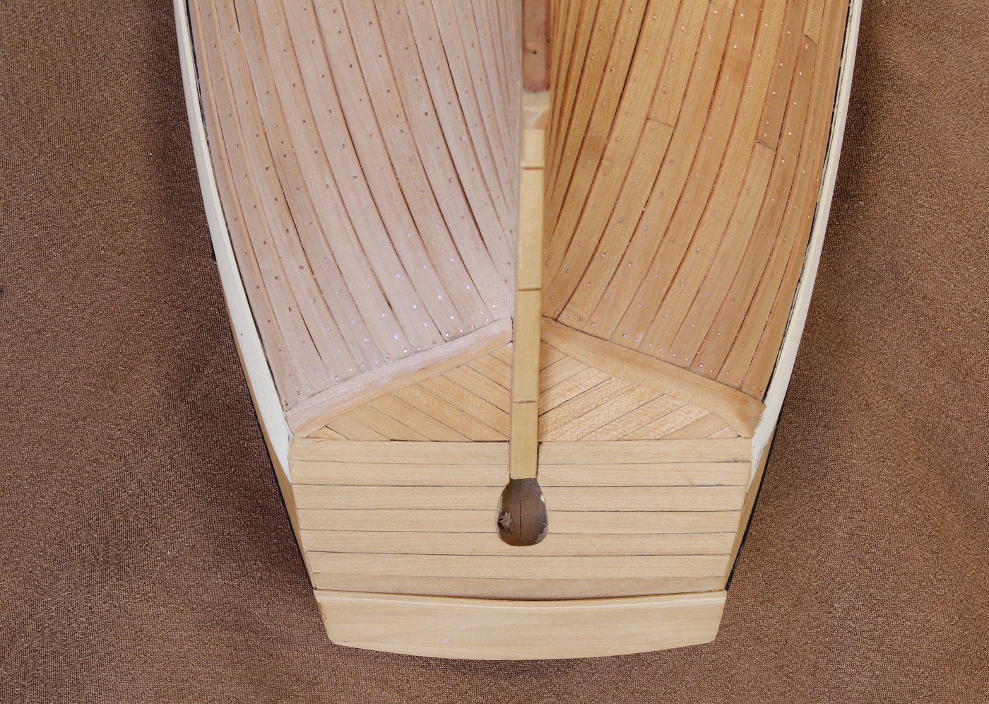
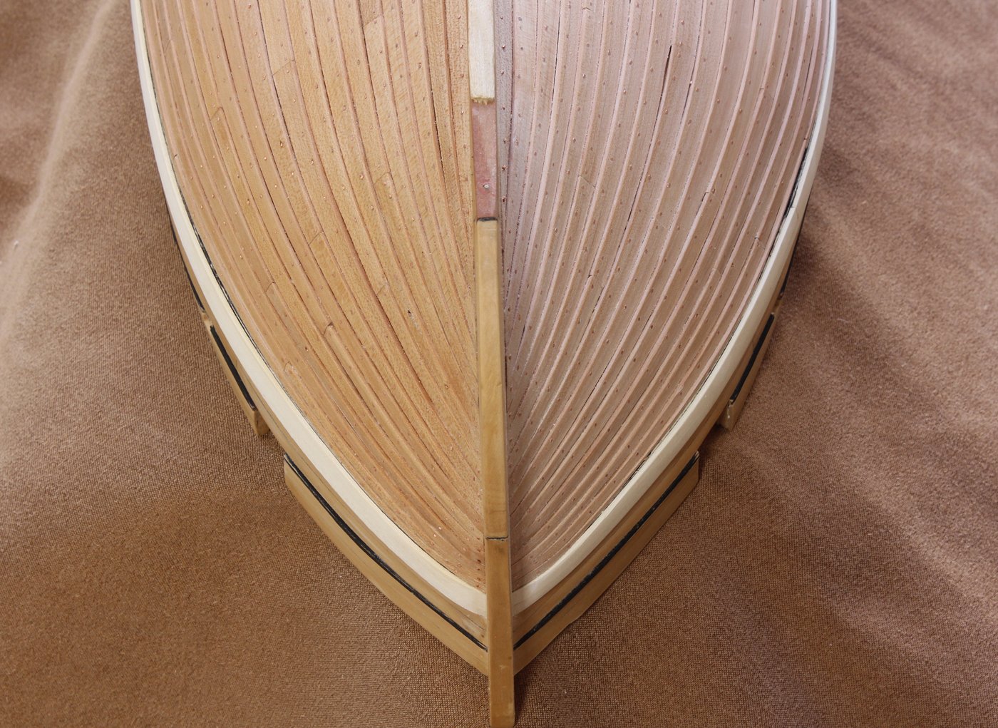
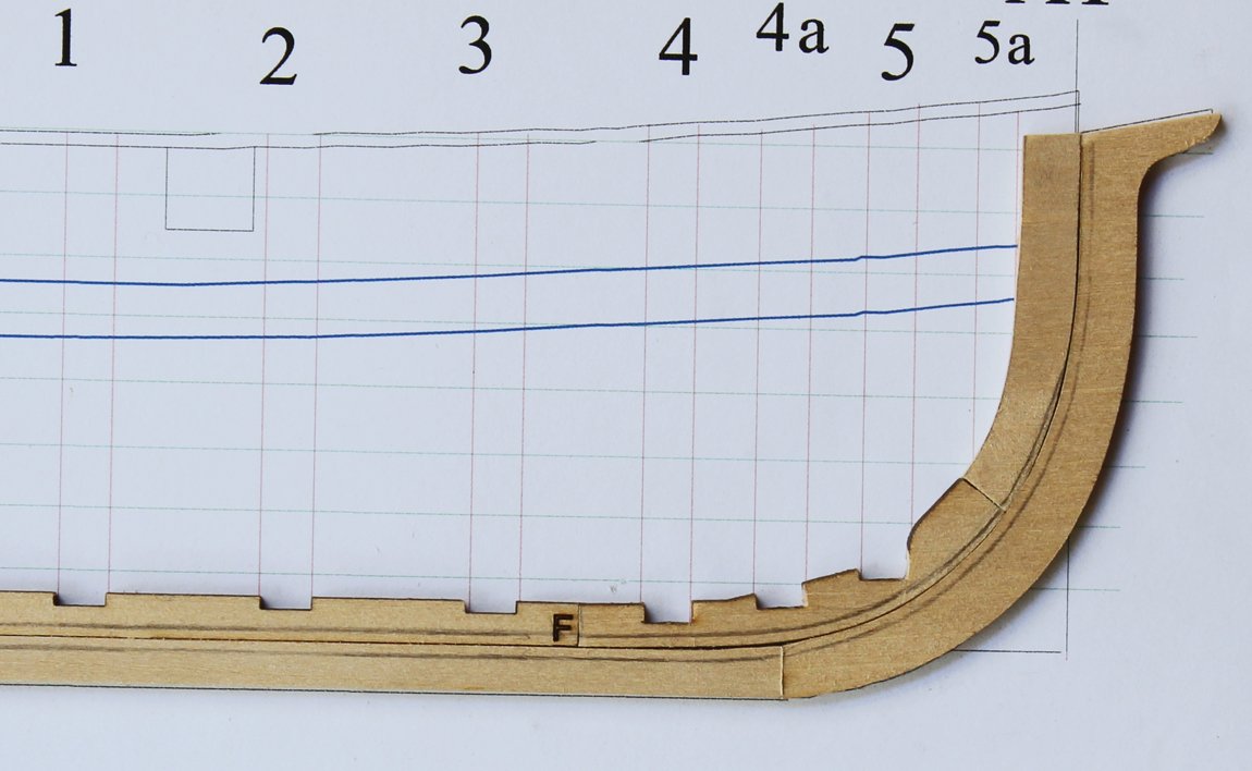
You are correct. The bevel continuously changes from the keel to the top of the planking, ending up at 90 degrees, just like a mortice. Think of it this way... On a typical kit build, you undercut the end of the plank so that it lays flat against the stem; at the keel you do the same thing to the side of the plank. On a real ship, the ends and sides of the plank remain at right angles to the face of the plank. To accomplish this, we need a groove, or rabbet, to seat the end or side of the plank into. The rabbet is always 90 degrees. Since this hull is bluff-bowed, the planks intersect the bow at almost a right angle in the upper planking belts. On a clipper ship, the angle at which the plank meets the stem will not change so dramatically. In similar fashion, if this were a flat-bottomed boat, the rabbet on the keel would be at a right angle to the keel, not at a +/-45 degree angle the way it is in the forward part of this ship. In the picture below, there is a smooth line extending from the keel up the stem. As the angle that the planking intersects the stem increases, the angle of the rabbet also increases and the overall width of the rabbet diminishes.
I hope I am making at least a little sense.
-


NRG Capstan Project
in - Build logs for subjects built 1751 - 1800
Posted
Now that the deck structure is complete, it is time to build the capstan step. There are three parts to the step and in real life they would be connected with half lap joints. To keep things simple, on this model they are glued together side-by-side. The middle piece is thicker than the outer pieces. This adds strength to the area where the capstan spindle extends through the step. The extra thickness is added as a separate piece. Items 6 and 8 are the outer pieces and 7a1 is the upper part of the middle piece. 7a2 is shorter because it fits between the beams.
Throughout the build log you will find discrepancies with the instruction set. This is because, as the build was progressing, I sometimes discovered better ways to accomplish a task. The following picture shows the step glued up, with holed drilled for the bolts into the beams and the bolts for the brakes. It is easier to defer drilling these holes until the step is mounted on the beams. All sharp edges are rounded over. The hole has been drilled for the capstan spindle. This was done with a standard drill because of its size. The last picture shows the step temporarily installed onto the deck assembly.