

tlevine
-
Posts
2,020 -
Joined
-
Last visited
Content Type
Profiles
Forums
Gallery
Events
Posts posted by tlevine
-
-
-
-
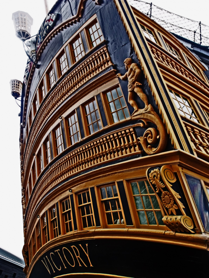
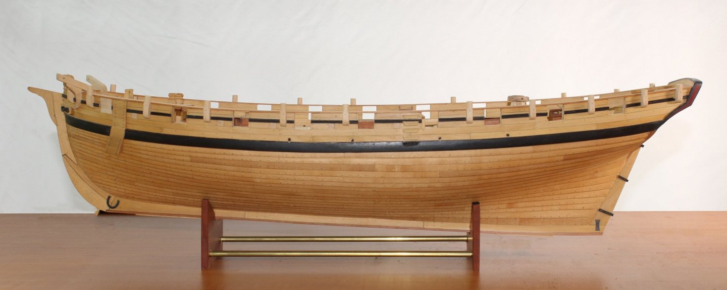
Don, your work is great. I have a question about the paint scheme on the quarter galleries. You show ochre paint extending onto them. When I built her several years ago, my research showed that they were completely black, as seen in the attached photo. Is this an era-specific schema?
- drobinson02199, GrandpaPhil, zappto and 2 others
-
 5
5
-
Welcome. Never be concerned about your skill with English. We are all here for the same reason... love of our hobby.
- Gct86, mtaylor and Keith Black
-
3
-
Welcome, Pete. If you are a member of the NRG, in addition to MSW, let one of the mods know so you can have the logo added to your name.
- Keith Black and mtaylor
-
2
-
-
-
Thanks to everyone for the likes.
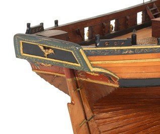
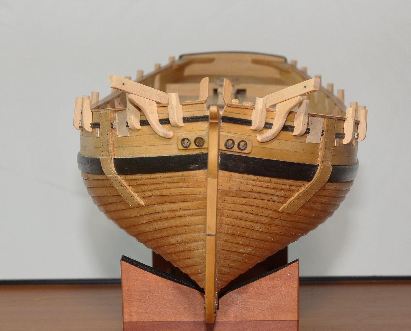
Thank you, druxey. Your explanation was much more explanatory than anything I would have said. The fashion piece was a pain to fabricate because of the compound curves. But by following the little-bit-at-a time approach, I ended up pleased with the result. As you can see in the picture, the model does not have a fashion piece. In fact, the aft ends of the hull planks are unusual; typically the lapstrake would have gradually diminished to a smooth surface.
- druxey, hollowneck, Bitao and 7 others
-
10
-
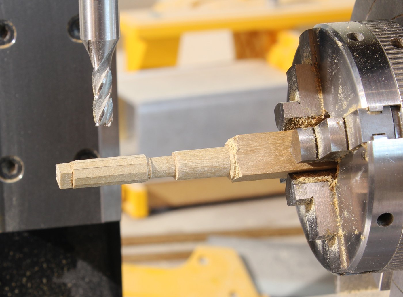
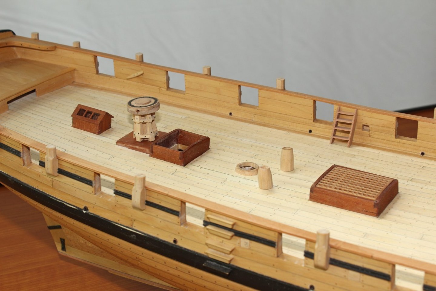
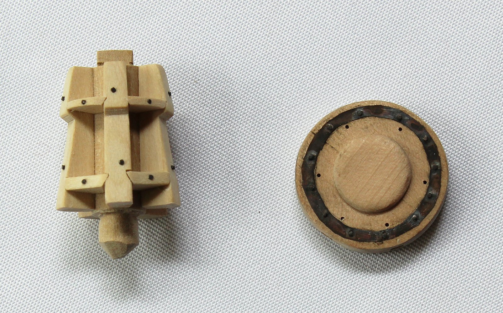
It has been almost two months since my last post but I have been busy doing small projects. Having recently completed a capstan in 1:16 scale, it was time to duplicate my efforts at 1:48. If you have purchased the Capstan Project, I used the approach outlined in the advanced version. The capstan on a ship of this size and from this era has five whelps and six bars. I turned the spindle in a lathe and then used a mill to make it ten-sided. The pencil marks are to help the edges stand out.
The whelps were glued-up as a sandwich; the thickness was the maximal thickness of the whelp. The sandwich was then glued to a block of wood, which was put into the mill vice. The face was milled and the whelps were separated by soaking in isopropanol. I made a few extra to allow for mistakes. The whelp is wider at the bottom and on its face. The final shape was achieved with a sanding stick.
The drumhead was made from four semicircular pieces and a cap. I used thin adhesive-backed copper sheet as the iron ring. I used liver of sulfur to give the copper a patina.
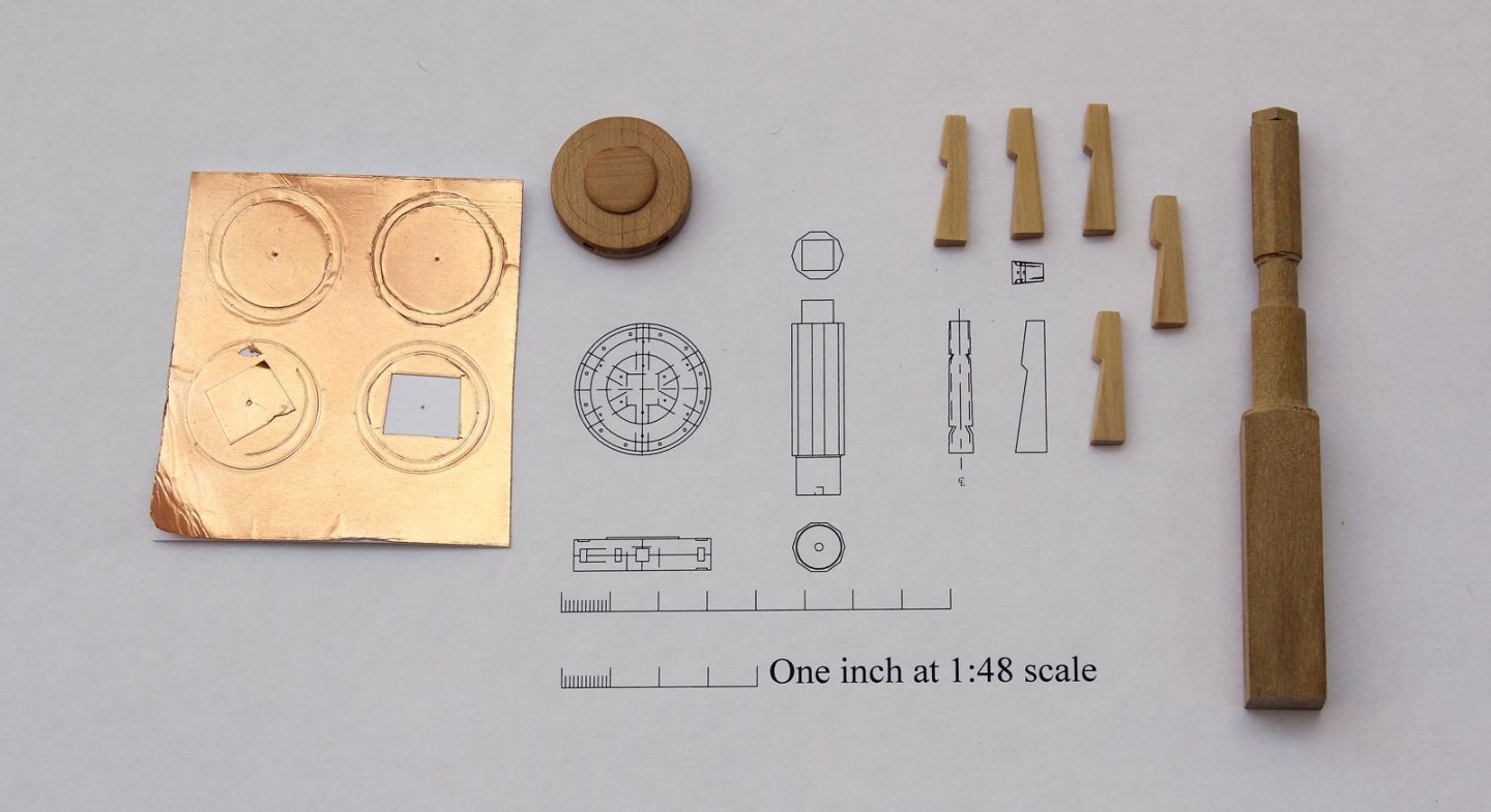
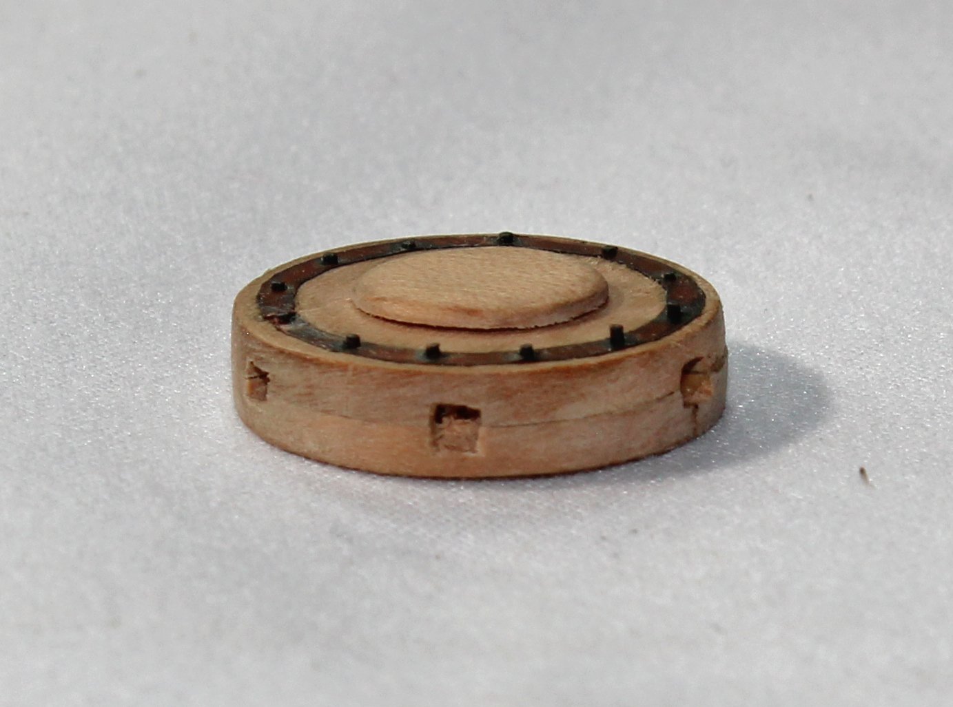
After the whelps were glued to the spindle, the chocks were made and installed and the bolts were installed. The iron ring looks much better than the photo would suggest. And the final result...

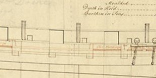
The next item I needed to address was the decorative molding. The plans show the molding at the level of the bottom of the gunports. The model shows the molding halfway up the gun ports. The plan shows the bottom of the oar ports raised by the width of the molding. The model shows them at the same level as the gun ports.
-Warship-Brig-Sloop-14-guns-1a.jpg.ac7b3c0252e9b36bea34f3920ccf6ab1.jpg)
As it turned out, I (accidentally) built them at the same level, as shown on the model. If I left the molding where it is seen in the plan, it would have gone through the oar ports. So my choices were to rebuild the upper works to lower the oar ports or raise the molding, as seen on the model. I went to the RMG site and looked at other models with oar ports; they were most commonly positioned at the same level as the gun ports. Therefore, I decided to move the molding instead of the oar ports.
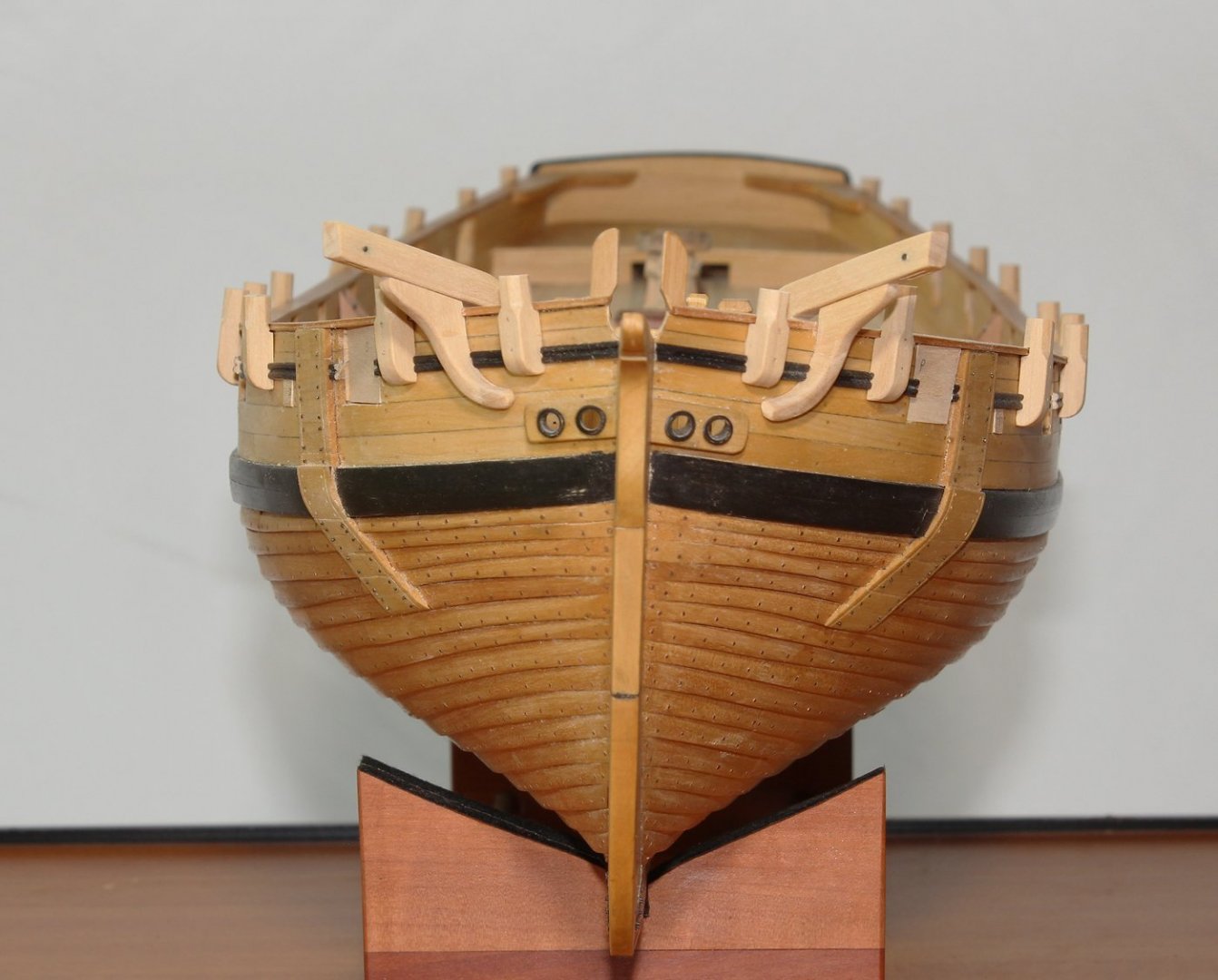
The ship has eleven swivel gun mounts on each side, although she only carried eight guns. These were located per the plan. They were notched to fit over the rail. Bolt holes were drilled. The metal work will be installed later.
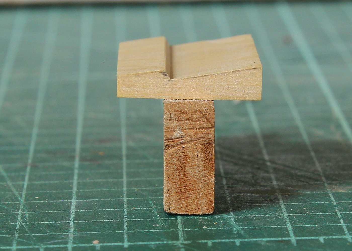
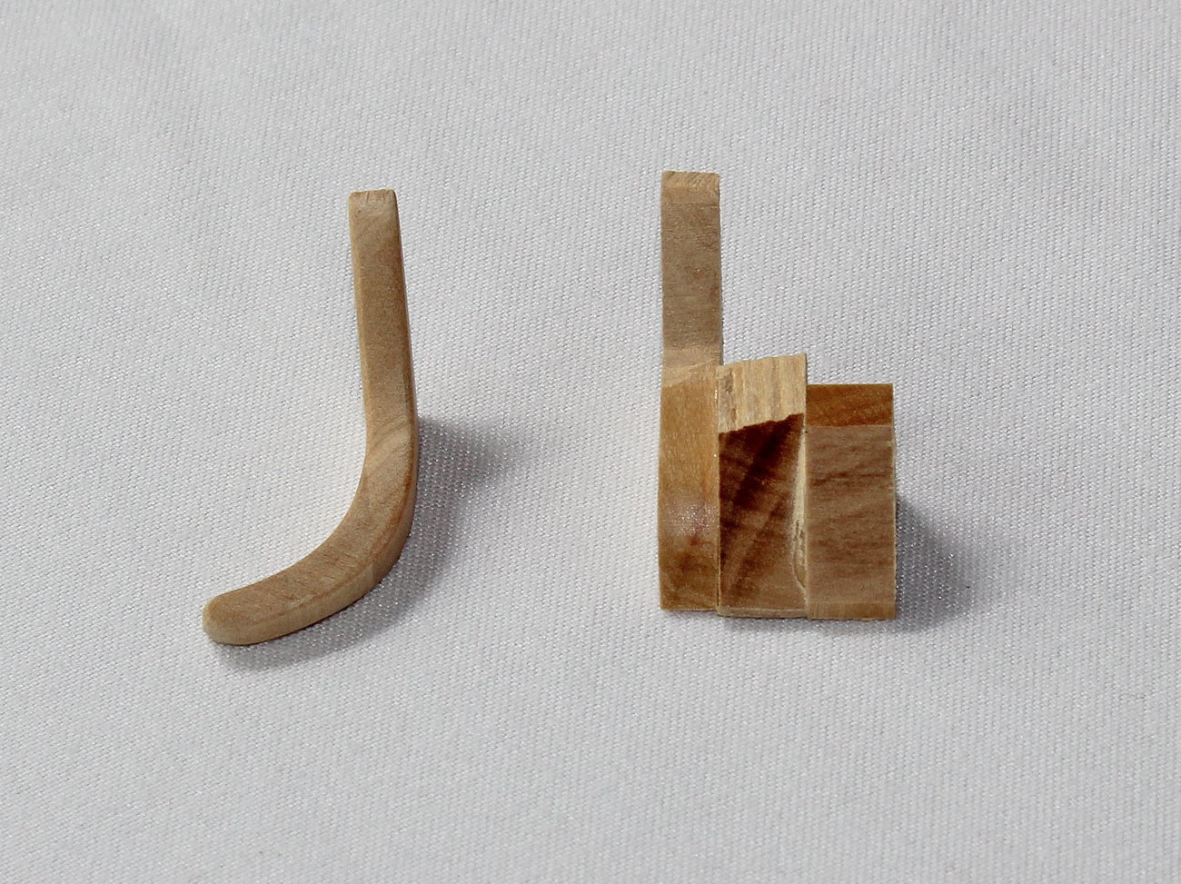
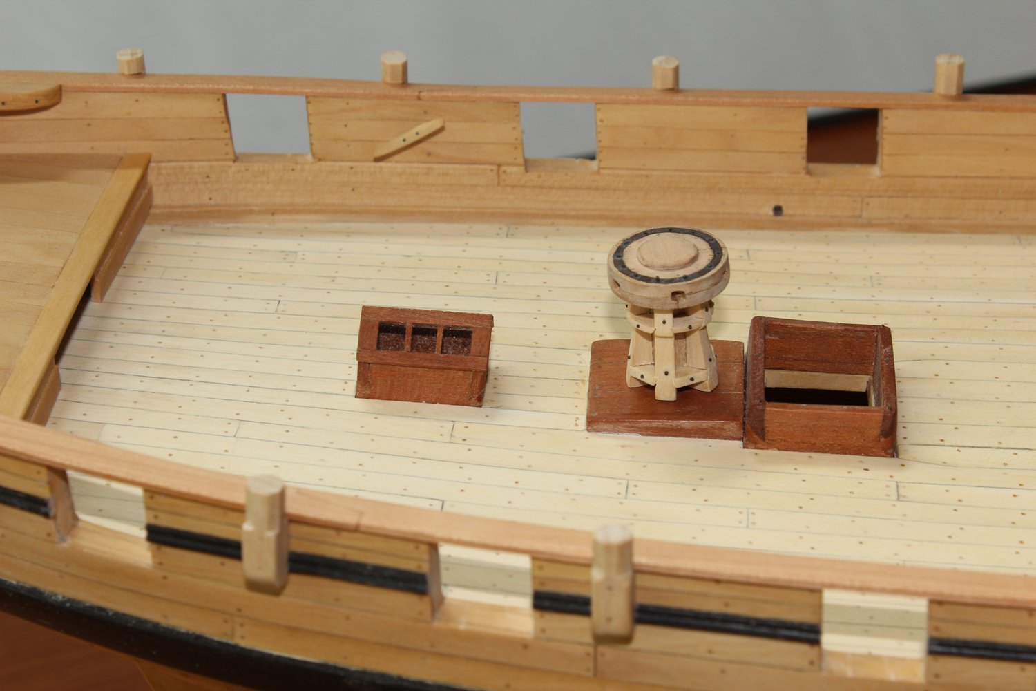
The cathead and cathead knee were made next. The cathead was sawn from a single piece wood. Two sheaves were installed. The cathead knee was made up of three pieces, as seen in the picture below; the final shape was attained with sanding drum and disc. The cathead and knee were then temporarily installed. No finish has been applied to either the swivel posts or the cathead. As you can see in the third picture, the tops of the swivel posts have not been shaped yet. They will be horizontal across ship and will parallel the shear when seen from the side. Also temporarily fitted are the first oar port and gun port covers. They will all be hinged horizontally.
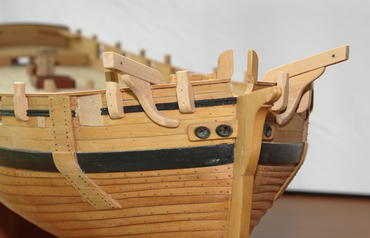
Other small items which have been installed are the cleats (three per side) and the mast coats. The entry ladders, pumps and capstan are temorarily in place.

- Cathead, Tigersteve, G.L. and 17 others
-
20
-
Looks very nice. Your setup is a lot fancier than mine. I got lucky and found that the block of wood that holds my end mills was just the right height for the vice and live center.
- mtaylor and usedtosail
-
2
-
-
-
-
Looks very nice. You will also find that the boxwood is easier to make grating out of, especially at smaller scales.
- usedtosail and mtaylor
-
2
-
-
They look great...better than mine! I admit that my milling skills are not the greatest.
I hope I do not disappoint you on the 21st. The last part of the presentation criticizes my first "real" model...and I am not very charitable to myself.
- Cathead, usedtosail, mtaylor and 1 other
-
4
-
Although I own an electric plank bender, it rarely sees any use. I have switched over to a heat gun designed for circuit board manufacture. The heat is directed to a small area and there is no scorching of the wood.
- Canute, mtaylor and thibaultron
-
3
-
The bad drawing has been modified. I am having others look at it for confirmation.
- druxey, usedtosail and mtaylor
-
3
-
Tom just brought to my attention a problem with the printed plans. The plans themselves are correct but the scale on Part 104 (and possibly others) is off. I will go back and double check everything over the next few days. The takeaway lesson here is that you need to build from the measurements, not the printed page. I can hear the four engineers who reviewed my work now...they did not want me to put any scale on the drawings for this very reason.
- mtaylor, usedtosail and druxey
-
3
-
We have all done something like that before...at least 100 times.
- Cathead, mtaylor, usedtosail and 1 other
-
4
-
Paper wrapped around the bit works also.
- Canute, Ed Gibbons and mtaylor
-
3
-
-
An inspiration. Thank you for sharing.
- giampieroricci, mtaylor and FrankWouts
-
2
-
 1
1
-
Great start. Those cleaned-up mortises look crisp.
- mtaylor and usedtosail
-
2


An old manuscript titled Mostly for Model Ship Riggers, especially Hal
in New member Introductions
Posted
Folks, the bottom line is this, the NRG leadership investigated this last year. The Guild not interested in publishing this manuscript. Mr. Davis has not even been on MSW for ten months. There is no need for further discussion.