tlevine
-
Posts
1,944 -
Joined
-
Last visited
Content Type
Profiles
Forums
Gallery
Events
Everything posted by tlevine
-
 Thanks for the clarification, Druxey. It's the perfect thing to fix while waiting for the hull planking to dry. Danny, I am afraid you are right...but I will post occasional updates so you know I haven't given up the ship.
 -
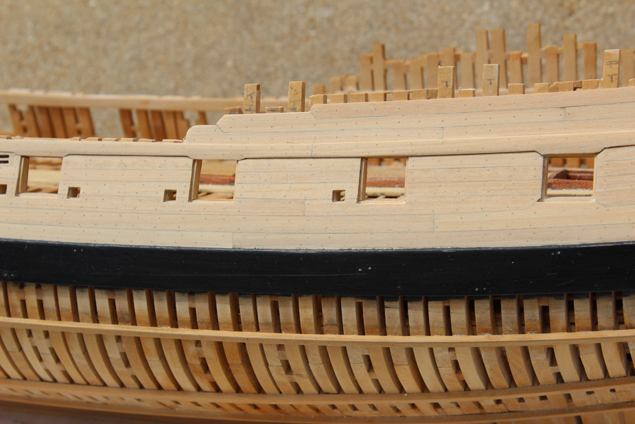
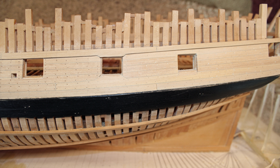
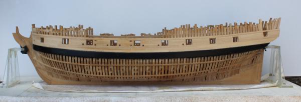
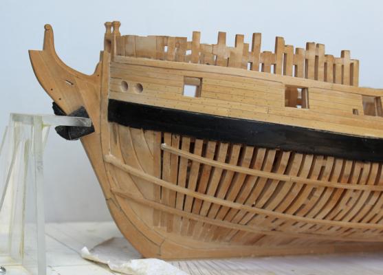
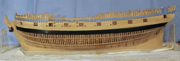
Ben and Mark, thanks for the support. I have reached a milestone...the upper works' planking is completed! I left the frame ends protruding above the level of the top rail to protect the upper edge of the planking. Now you can even tell which frames have timberheads associated with them. Because the only things keeping the starboard frames in line are the ribbands and the filler blocks above the top of the frames, this side was not cut down. Now I have a question. In TFFM it states that where the sheer strake "...widens down to the ports there is a change in surface level to produce a smooth, continuous chamfer line..." I interpreted this to mean a smooth chamfer to the top of the port. Another interpretation would be to make the lower part of the strake the thickness of the hull planking and the top part the thickness of the sheer strake. Looking at a contemporary model of Atalanta did not show enough detail for me to tell which direction to go. If someone could give me some direction, I would appreciate it. I left things so that it would be easy to convert if my interpretation is wrong. On to the lower hull planking.
-
What's worse is when the dog tells us we're crazy. (Which of course we all are.)
- 1,048 replies
-
- 2
-

-
- cheerful
- Syren Ship Model Company
- (and 1 more)
-
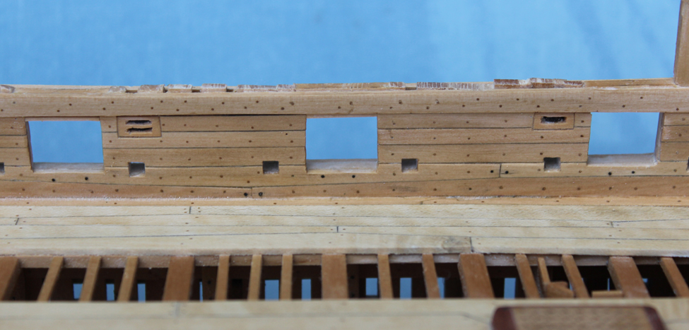
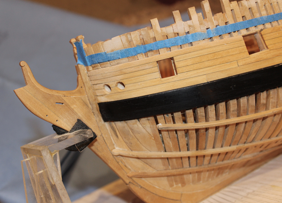
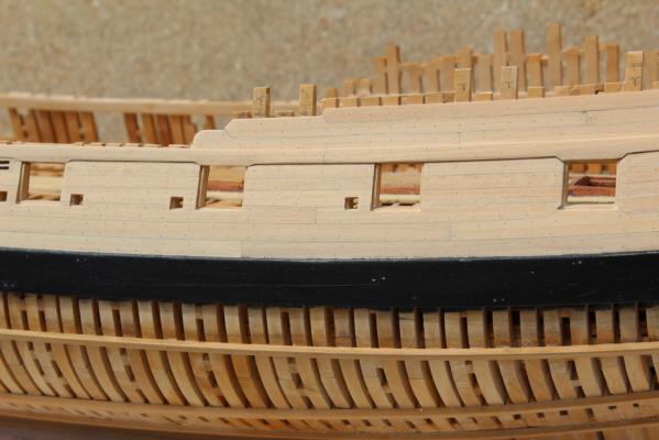
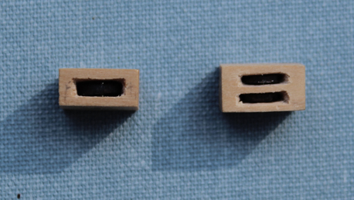
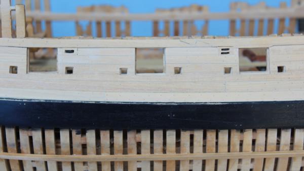
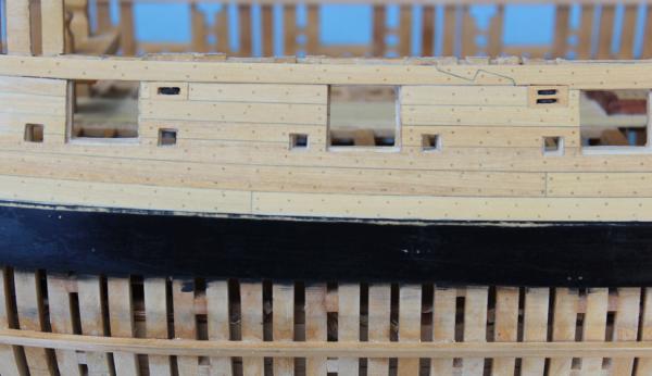
Thanks, Kees. We are usually our own worst critics. Now that the sheer strake is installed, it is time to attack the fixed blocks. There are two fixed blocks that pierce the hull. One of them has two sheaves and the other only one. They are pretty straight-forward in construction. First the block's shell is cut and dry-fit. Next the slots for the sheaves are marked out, drilled and then finished with needle files. The hole for the pin is drilled and the block is put back into the hull. It is much easier to drill the slots for the sheaves prior to shaping the sides. The inner and outer faces are sanded to conform to the shape of the tumblehome. I made the sheaves from ebony that I drilled out and shaped with chisels and sandpaper. Finally, they were sawn to thickness and installed. In the pictures there is too much contrast between the woods to actually see the sheave withing the slot. The blocks were removed, the sheaves and pin inserted and glued with CA, and the assembly was glued in place in the hull. The first photo shows the blocks glued and sanded in place. In the second photo the wood has been wiped down with a damp cloth to highlight the treenails. The slots on the inboard face need a little more cleaning up. The final appearance. I still have to insert some of the gun port liners but overall I think it looks pretty good.

-
I have a suggestion. Make your holding jig a "V" rather than a "U". It will hold the wood more securely. You can also use that jig to sand or plane down the spar to the correct dimensions. I always get worried when I put long pieces of wood into a drill chuck. Unless you can keep the speed very slow the wood whips about madly. Get some good poplar dowels from your favorite craft or DIY store for the other spars. Since you are into organization, make yourself some storage containers for leftover wood strips. Take some PVC pipe (I used 4" diameter) and cut off 18-24" lengths. Stack and glue them together with PVC cement to keep your wood organized.
- 175 replies
-
- 1
-
-
- 18th century longboat
- model shipways
- (and 1 more)
-
Long handled surgical scissors
tlevine replied to RGL's topic in Modeling tools and Workshop Equipment
Either a Metz or curved tonsil scissors would give you the reach without excess blade length. I am sure you could pick up either of these on EBay or a a used medical supply house. Please remember that these scissors are designed to cut tissue, not thread. The largest diameter thread these types of scissors would cut without the end looking ratty is 3-0 (0.2 mm). -
Greg and Danny, thanks for the encouragement. Like so much of what we do on these models, the mistakes are only going to be visible to ourselves and the few other "crazies" of like mind. Hope to finish the treenailing this week. One thing was reinforced with this little escapade. If David's drawings to not exactly match the model...STOP. If I had done that at the time I installed the black strake, the rest would not have occurred.
-
Thanks, Ben. The treenails are castello, drawn to the second smallest hole on the Byrnes drawplate.
-
If you decide to order pear from Jeff, please have him send you a sample first or else commit to using all of the wood from the Lumberyard for another purpose. I purchased the pear for my Hannah from the Lumberyard (in billets which were milled later). I had no problems with the quality other than a few pin knots. I ordered an extra board of pear from Jeff and it was a very different color. Jeff's pear is "pinker."
- 887 replies
-
- 1
-
-
- hahn
- oliver cromwell
- (and 1 more)
-
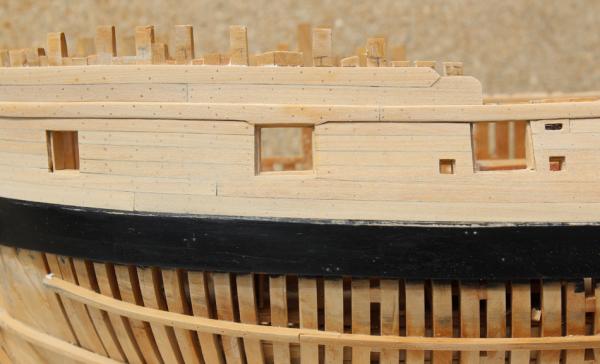
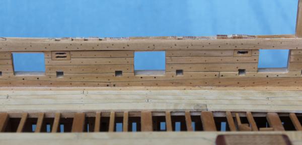
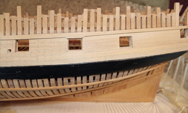
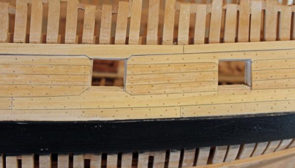
The sheer strake was installed next. This is 3" thick and is let down to the top of the gun port where the width of the upper planking would have been less than 5". There is a hook scarf amidships. I have cut down some of the timbers to just above the sheer strake. By leaving them a little long at this point I am preventing damage to the top edge of the sheer strake. I ran into two problems: one correctable and the other not. Although it is hard to tell from the pictures, my Dremel has developed a wobble in the shaft and consequently the holes are slightly oversized. I solved this by dipping the treenails in dilute glue before installing. Usually I install them with pressure fit and rely on the finish to seal them into place. It appears a new Dremel in on my horizon. You can see my general approach for treenailing in the following picture. I draw a light pencil line to indicate the center of the frame. Next, I pencil in the locations of the treenails. I use a carbide stylus to prick the wood so the drill bit does not wander. And finally I drill the hole. I start at the bottom and work up to the top. The sawdust drops down so by starting at the bottom I do not have to clean off the hull after each hole has been drilled. I sanded the aft area so show how the treenails disappear until finish (or water) is applied. Now for the relatively uncorrectable problem. As I mentioned before, I had to correct the sill heights to get a smooth run. This was accomplished by lowering the central gunports and raising the aft gun port and bridal port. I have already stripped the planking twice and began to be concerned about the integrity of the frame glue joints with the repeated application of isopropanol. Therefore, I decided not to strip the planking again even though the appearance is not perfect. You can see my shim on the lower port opening and the height that had to be removed at the top. I am not pleased with it but weirdly feel better for showing the problem to whomever reads this log. I guess that means I need a life! The wood was wet down to show off the treenails.
-
After soaking, I typically leave the plank clamped to a former overnight to dry before gluing with PVA.
- 1 reply
-
- 2
-
-
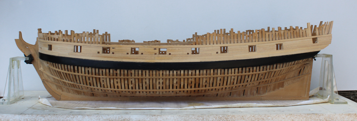
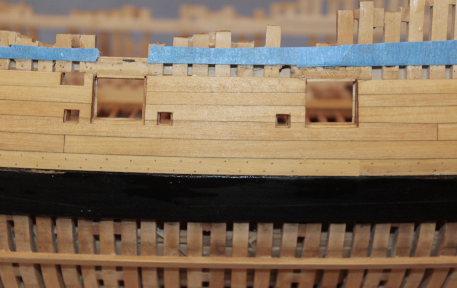
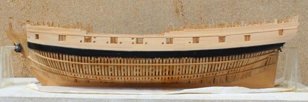
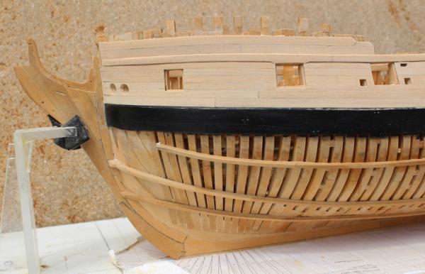
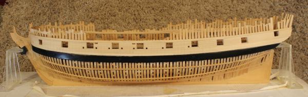
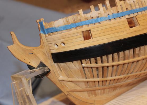
At long last the installation of the upper planking is progressing. After installing most of the planking up to the level of the top of the gun ports I discovered that the height of the lower sill was 2 scale inches too high. However, I also determined that the height of the bridal port and the last gun port were correct. To make everything perfect would have required removing all of the spirketing and the string in the waist. Well, that wasn't going to happen so I did the next best thing. I raised the sills of the bridal and aft gun ports one inch and lowered everything else one inch. There was minimal damage to the appearance inside the hull with this approach. In the first picture it looks like the aft port is too low. This is an optical illusion caused by the narrowing distance between the main wale and the bottom of the gun port as one moves aft. I removed the gun port liner after the outer planks were installed to get a better edge. The pictures show some of them reinstalled. I have tapered the thickness of the planking to 2 1/2". The sheer plank will be 3". I still have to finish sand the planks, reinstall the rest of the gun and sweep port liners and finish the opening for the sweep ports inside the hull. The scrapes in the main wale paint will be addressed when all of the hull planking is completed.

-
Martin, I think your problem is the final result of the situation you had with the fore plywood. I would suggest running a batten along the inferior and superior edges of the gun ports and mark out any necessary adjustments on the plywood sheeting. Then check the side walls of the ports for plumb. Your run of planking should provide enough structural strength that the gap between the plywood parts will not be a concern. Don't make any gun port adjustments on the plywood until you have installed a few rows of planking and don't put any planking butts adjacent to the junction of the plywood pieces.
- 467 replies
-
- 1
-
-
- fly
- victory models
- (and 1 more)
-
Thank you Nils. Richard, the sills are the correct dimension but are positioned 2" too high. This affects the overall shape and width of the sheer strake but once everything is completed it should look ship shape. I have a suggestion for anyone installing planks above the wales. After the run of planking is marked on the frames, clamp a narrow spline just above the line so make sure you are happy with how the run looks overall. I found it difficult to keep everything aligned properly with all the fenestrations from the gun and oar ports. This helped me a lot when I replaced the planking.
-
Thanks everyone for the encouragement. My biggest problem was that when I took the height of the lower sills of the gun ports off the NMM plans I did not realize that these were actually the height of the lined sills. Consequently, location of the gun ports are about 2" too high (the top of the gun port was measured off the port framing, not the plan so the actual size of the gun port is correct) and the run of planking had to be modified from the diagram shown in TFFM. I finally figured this out when most of the planking below the sheer had been installed and nothing looked right. After removing the planks I drew up a new planking diagram to compensate for the port height.
-
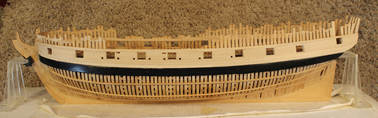
It has been a while since anything was posted but I have a good excuse. I had installed the black strake and most of the upper planking. When I returned the next day to finish the planking I decided that I did not like the looks of it and spent several hours of quality time with the isopropanol. I hope to have some pictures of the redone planking soon.
-
Dan, pick up a 10-pack of each of your favorite sizes. Although I am sure the bits work better with a drill press, don't own one and have not problems using a battery operated Dremel or my Emesco dental engine. They do break if you bend them but I have also drilled hundreds of holes with a single bit if I am careful. I would not use the Dremel flex shaft as there is too much chatter in the handpiece.
-
Bob, I love how, with your research, you have transformed this kit into something remarkable.
- 277 replies
-
- 2
-
-
- model shipways
- 18th century longboat
- (and 1 more)
-
Dan, I drill the first hole, shape the band by wrapping it around the mast, remove the band, solder and then drill the band and then install it over the masthead. Carbide bits are brittle but they are no more expensive than HSS and once you use them you will never go back. I would start with a #76 hole and enlarge it from there to your desired size.
-
What type of drill bit are you using? I have resharpened carbide bits from drillbitcity that work much better than the HSS bits commonly employed. I normally drill my first hole, then wrap the band around the mast. After it is soldered, it is easy to drill through the soft solder you are using and the first hole acts as a pilot hole for the other end of the mast band. If you are blackening the band remember that regular solder will not blacken. You need to use Staybrite or Tix.
-
Before you decide to leave the frames as is, please check the plans and make sure that this does not impact some other part of the hull, such as gun ports, scuppers, etc. Making new frames is much easier than getting everything else in line later.
- 305 replies
-
- 4
-
-
- utrecht
- statenjacht
- (and 1 more)
-
If you are using actual surgical gloves (not medical examining gloves), the decrease in tactile feedback should be minimal. However, if you have a skin condition and you use powdered gloves you are opening yourself up to a whole new set of problems. The powder can sensitize your skin to the gloves themselves. Use only non-powdered gloves and rub your hands with a little mineral oil before donning them. Nitrile exam gloves, on the other hand, will reduce tactile feedback considerably but are hypoallergenic, unpowdered and extremely strong.
-
Thanks, Ben.
-
Great work on the chock. This entire build is full of "I thought that would be harder" and "That was easier than it should have been". Be careful of the latter because half the time that means it wasn't done correctly (voice of experience).
-
18' Cutter by Maury S - Scale 1:48 - SMALL
tlevine replied to Maury S's topic in - Build logs for subjects built 1751 - 1800
Looks very nice. I had some glue seepage on the interior but was able to remove it with scalpel blades and sanding sticks.