


garyshipwright
-
Posts
901 -
Joined
-
Last visited
Content Type
Profiles
Forums
Gallery
Events
Posts posted by garyshipwright
-
-
-
-
-
-
-
-
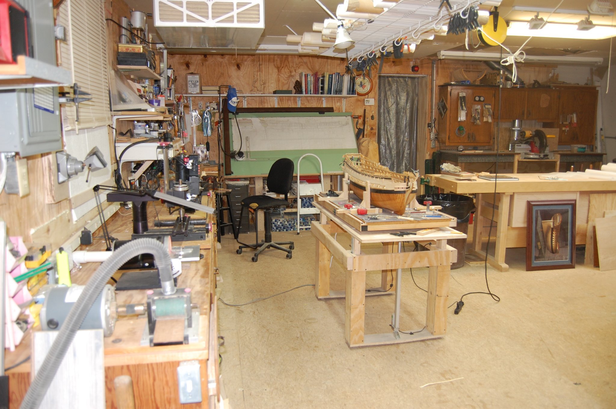
Thanks Tony. I really enjoy working in the shop but because of all the honey do's hard to get to spend much time in there. With winter coming I just may get to spend more time in there. Thanks Johann. The table top goes down to 2 foot 6 inches from the floor so at the moment gives me about 4 feet to work on her above her upper deck. Figure if I need a lower table then that, I just get some shorter electrical actuators but thats for the future. Gary
-
Hi Johann. Out standing job sir and the scissor lift looks good. I built mine a few years ago and the only item that I purchase to build it was the electrical actuators and power supply which were less then 75 dollars I believe. You can find good ones on ebay and amazon. I used the wood that I had in the shop and I believe that was plywood. Has come in real handy and am always moving it up or down to just to get the right height. I wanted to buy one but like JD said, they are very expensive. Since then I have put wheel's on it that fold up when am not moving it around which came from Rockler. Gary

- bruce d, GrandpaPhil, BETAQDAVE and 13 others
-
 16
16
-
-
-
Nice work good sir. Will be following your build with great interest. Gary
-
18 hours ago, stuglo said:
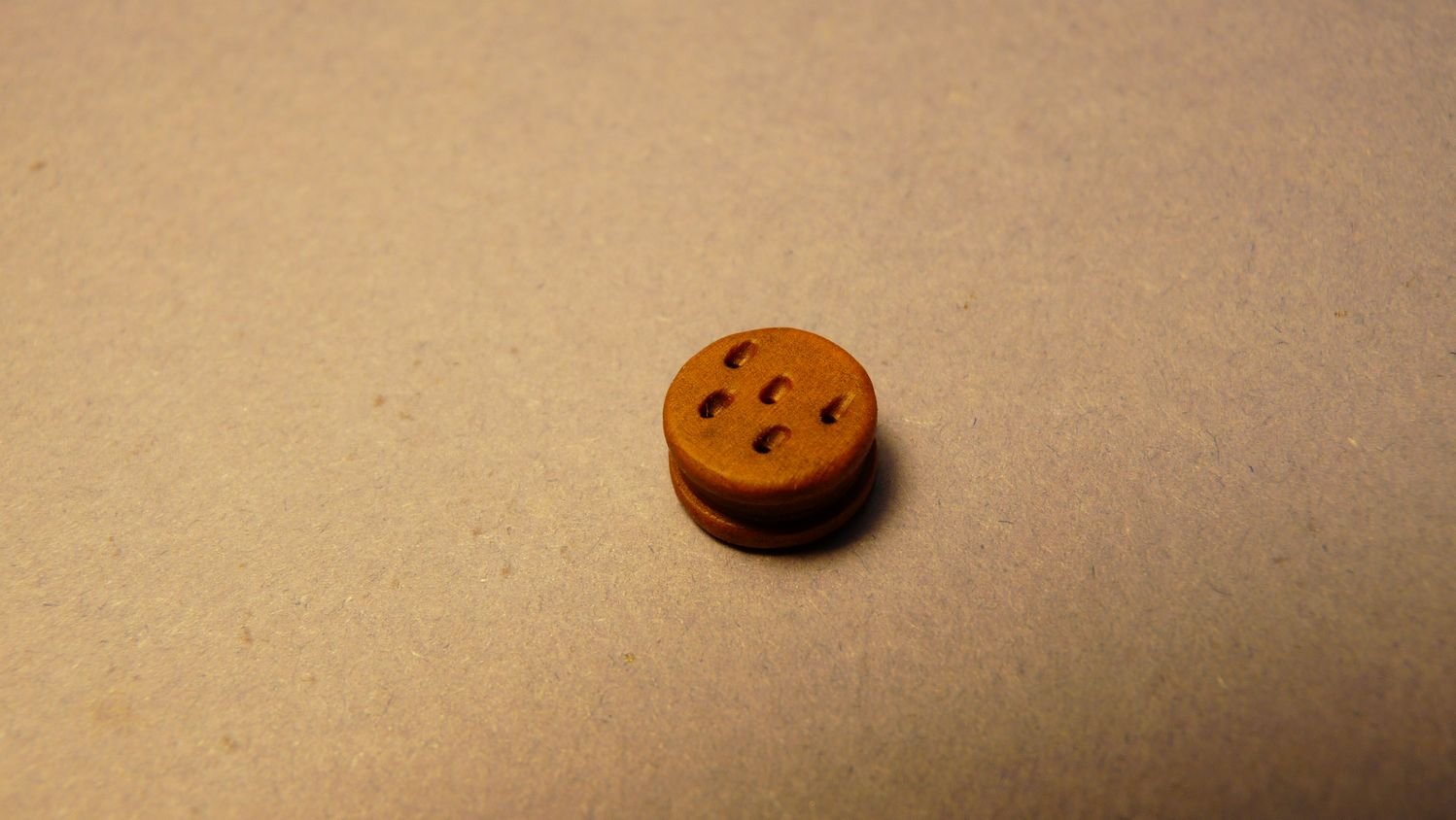
Depth Gauge
(adapted from TFFM and Kevin Kenny)
Necessary for accurate placement of deck clamps etc.
Materials-simple and to hand.
Required to be adaptable to varying width and depth of hull and curves that restrict fixed perpendicular “arm”
Therefore, system that moves both up and down, side to side and arc.
The axis-screw with nylon washer, wing nut.
Clamps, to lock position of sliding bar.
Later addition of pointed foot -broken 0.8mm drill bit
The whole turned 180 to mark the opposite hull wall.
(pictures posted on jig site)
Hi Stuglo. Do you have a link to the jig site? I like to take a look at it but can't seem to find it. Keep up the good work and she is looking good. Thank you Gary
-
Outstanding is the only thing comes to mind. As druxey said very impressive. Gary
- Forlani daniel and mtaylor
-
2
-
-
-
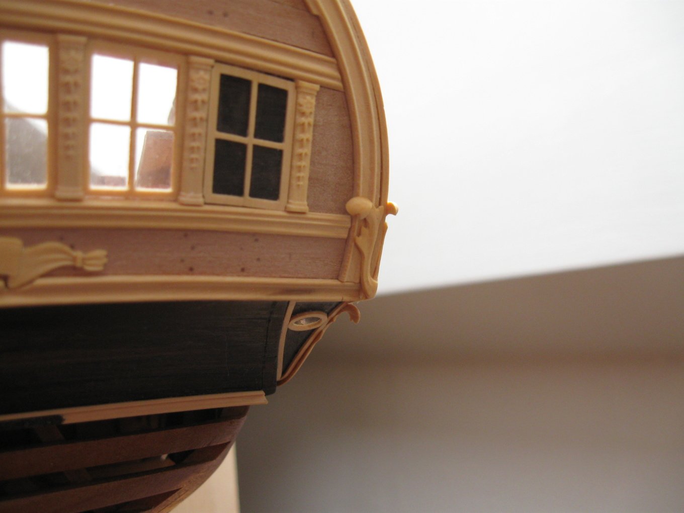
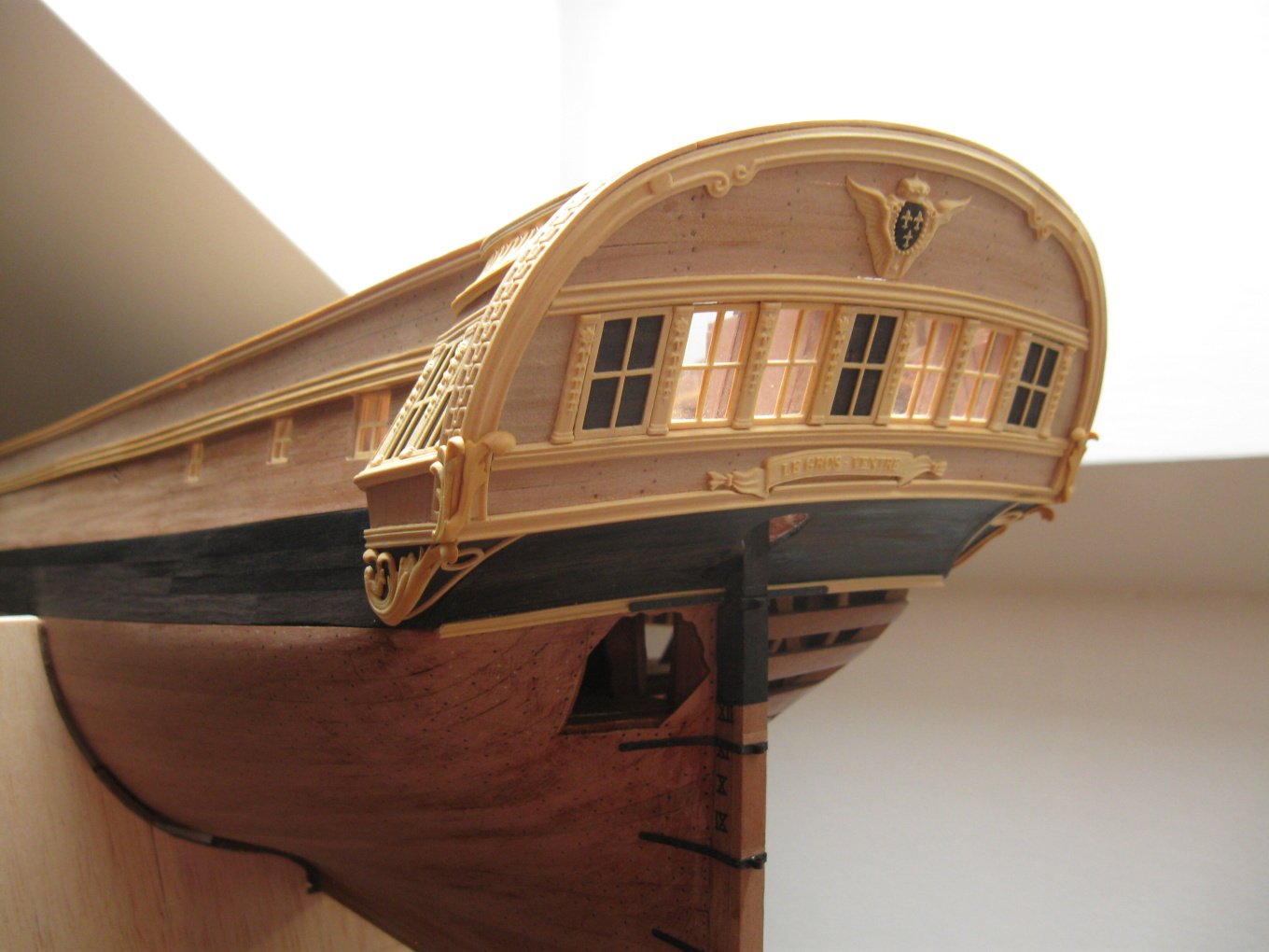
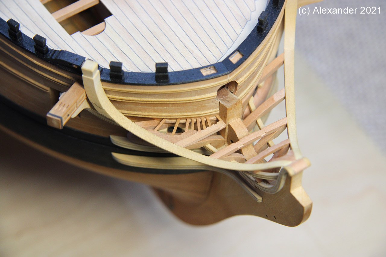
8 hours ago, Alex M said:
Hello and thank you all for warm words!
now I have reached a little but important for me milestone, all rails are done! And I'm satisfied with them...
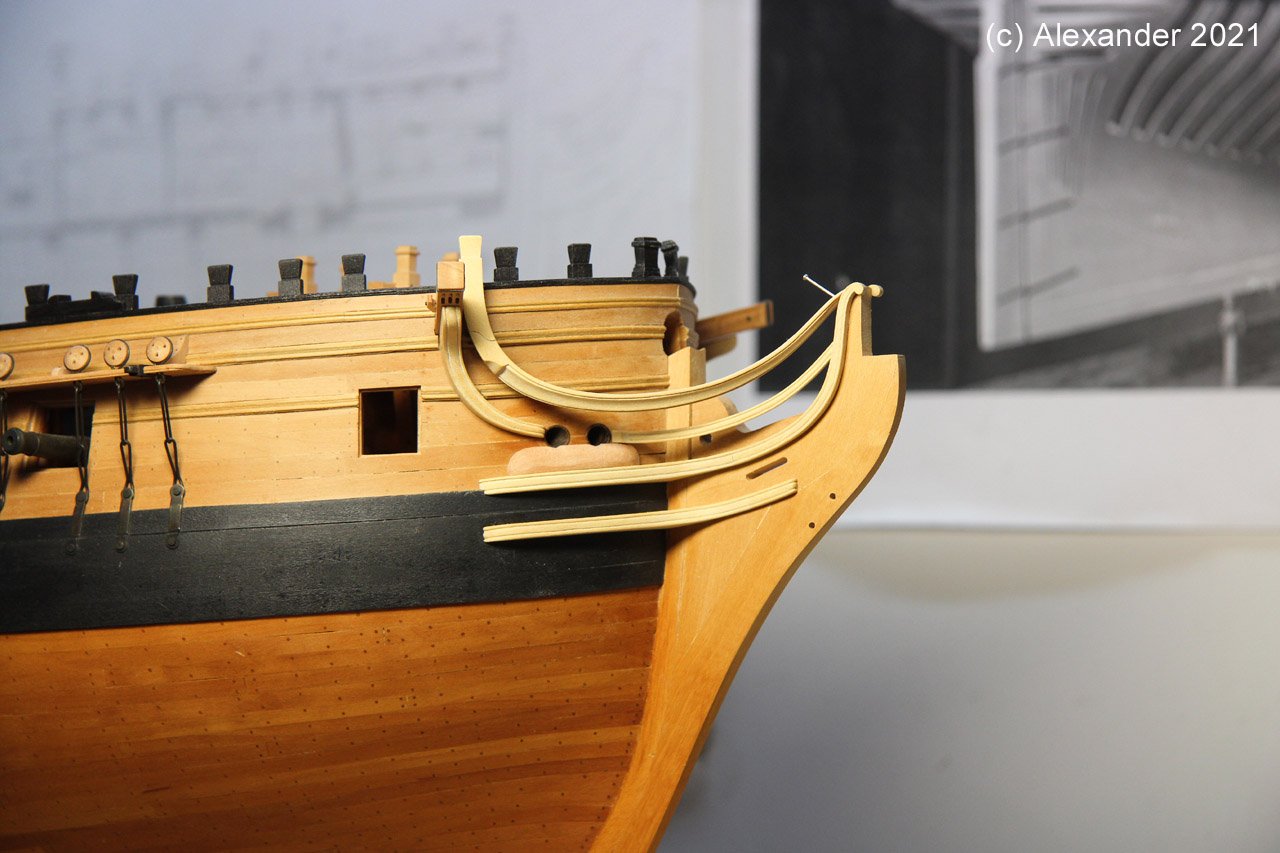
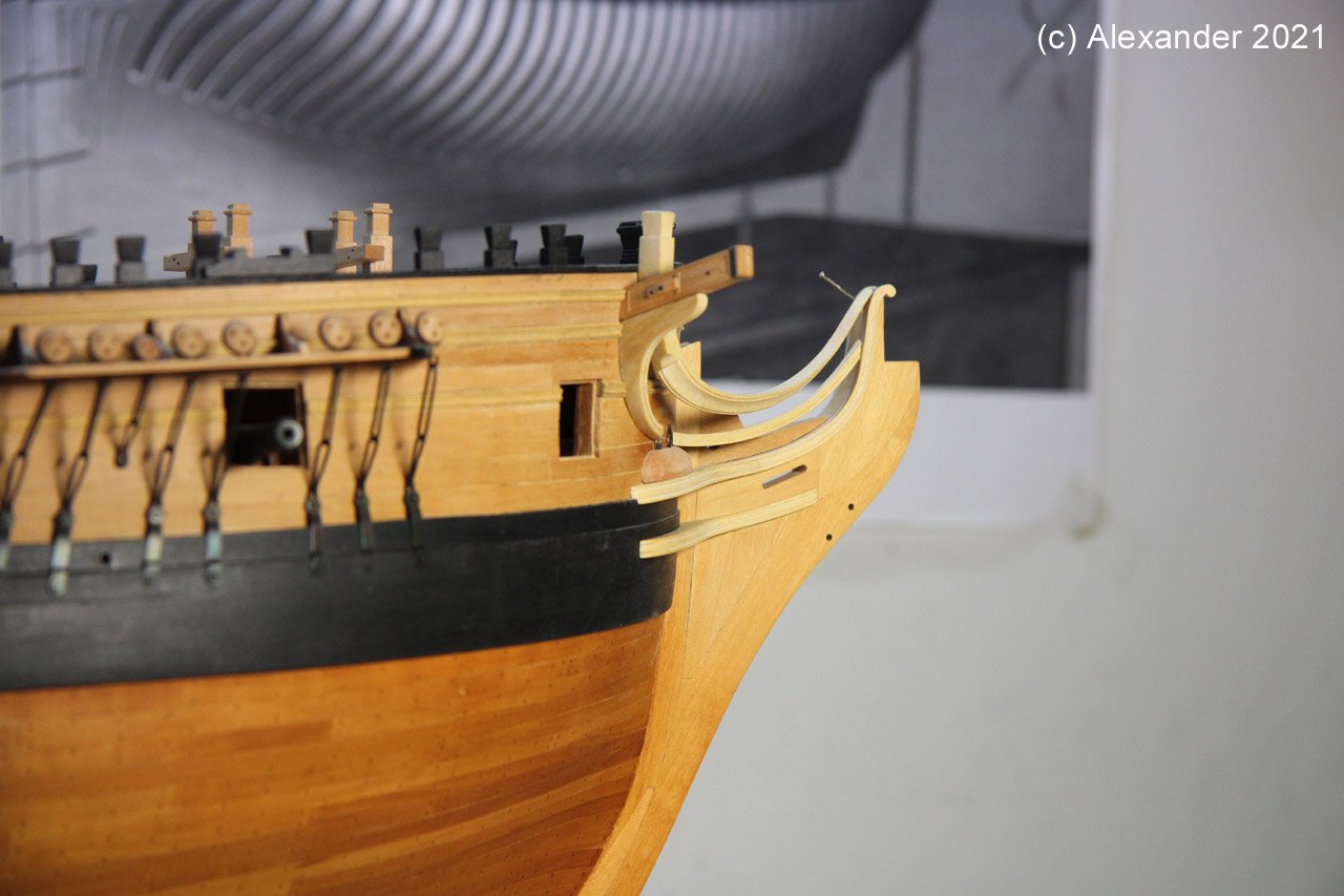
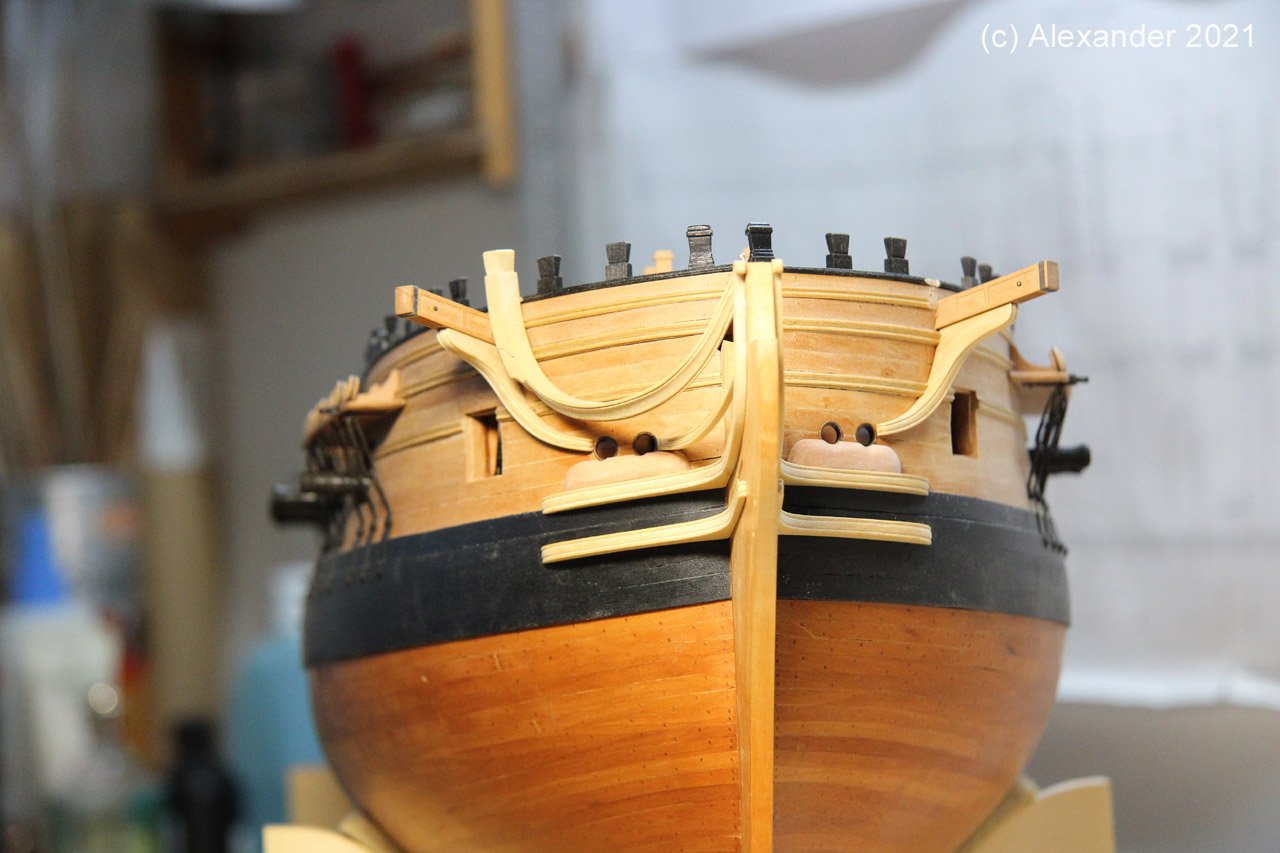
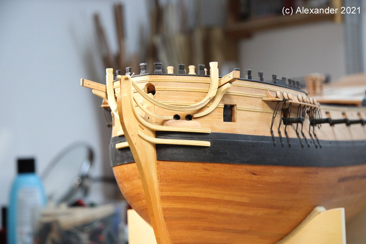
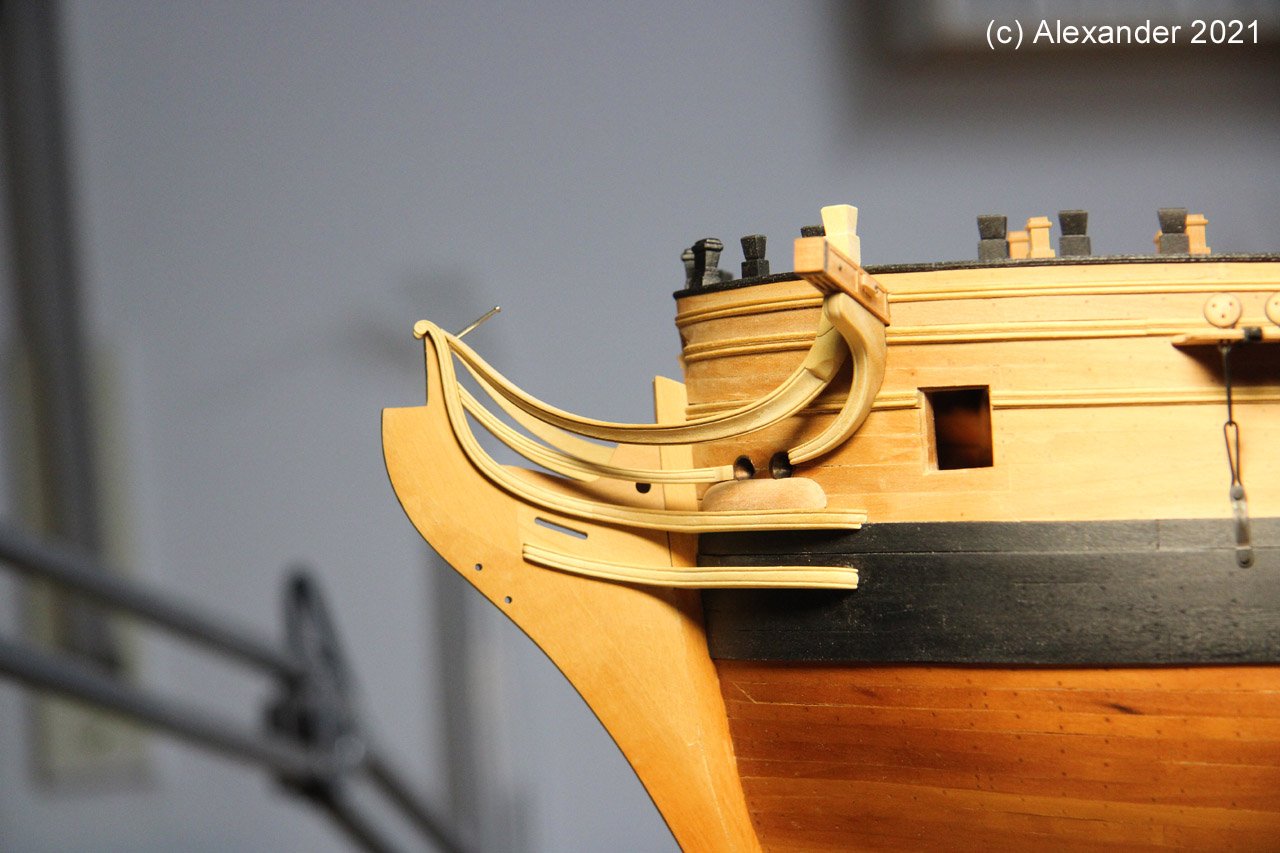
The next task are the head timbers...
Regards
Alex
looks outstanding sir, and look forward to your next update. Gary
-
Hi Clay, I tried to get the set that Marsalv showed but for some reason it would not let my order go through. I found what I believe is the same set that you show. Have you by chance got a chance to use them and look forward to what you think. Gary
-
-
-
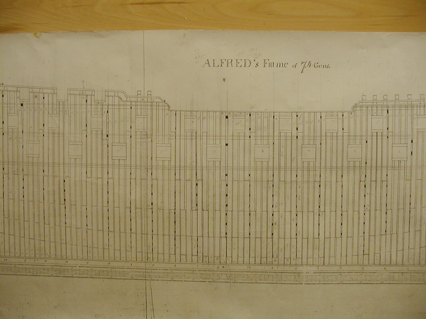
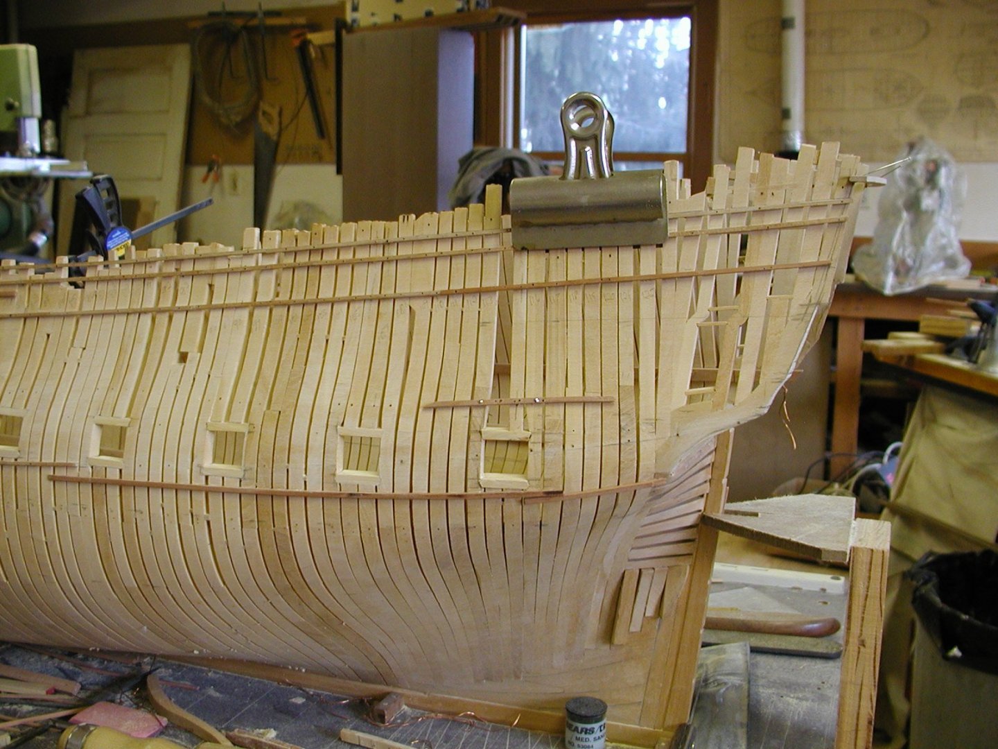
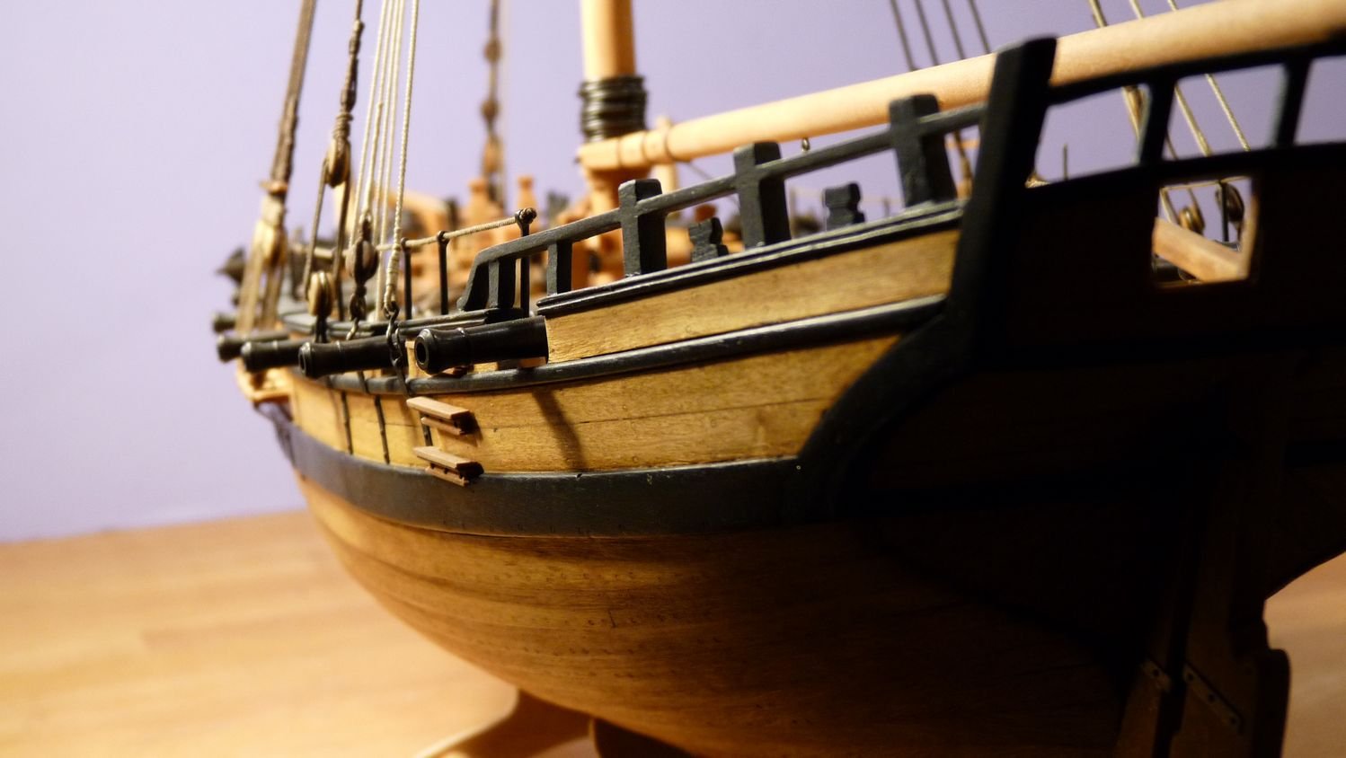
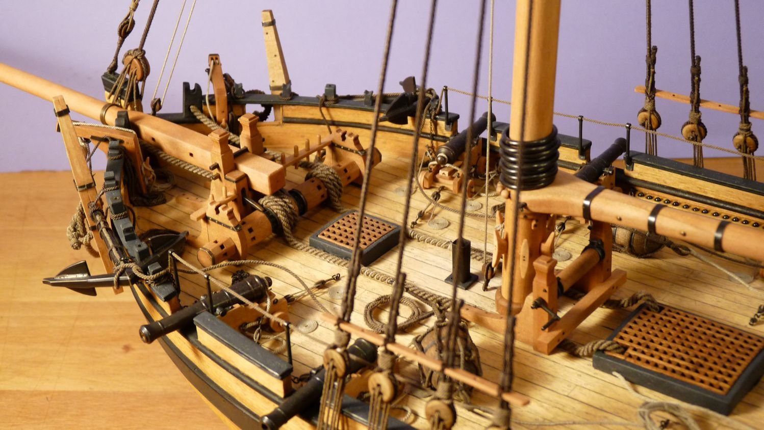
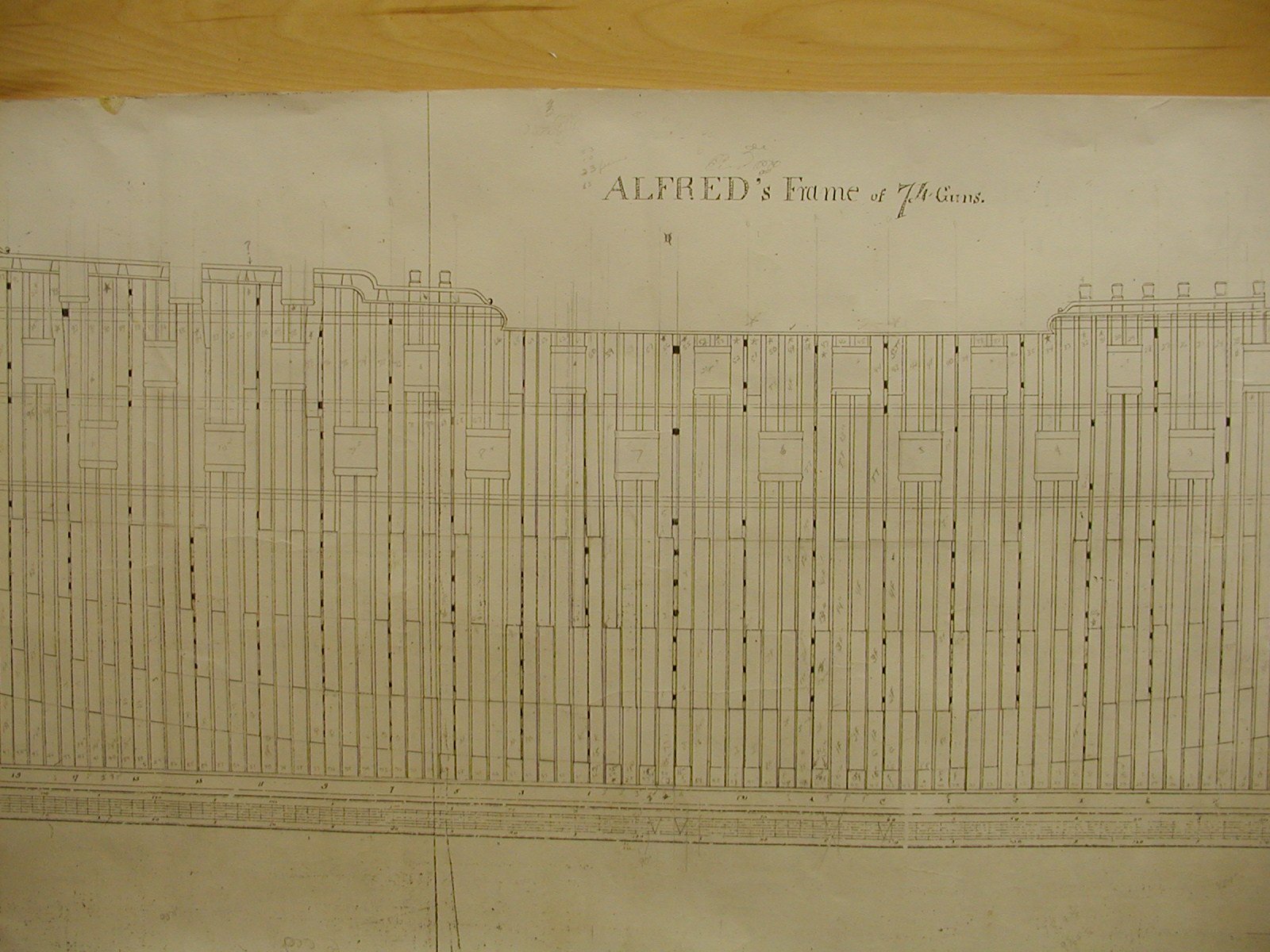
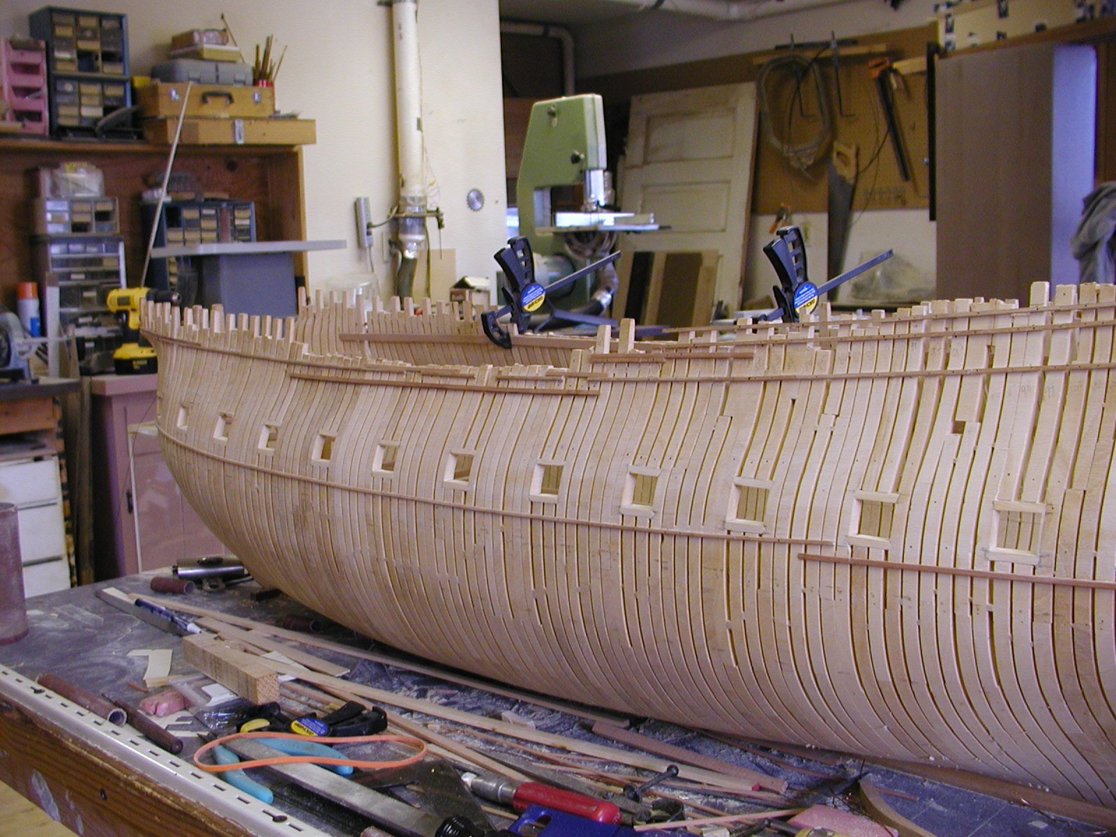
Hi Clay. Well good sir my thought process on the framing was I used butt's to hold the parts of the frame together that is shown on page 18 in Goodwin's book. Being a expert , thank you for that, but call my self more of a student who will never finish school. When i started building my frames I did use chocks to hold the parts together but being that you make about a 130 frames it takes awhile which is why I used the butt and dowel that hold's those parts together. Not as time consuming and once the planks are installed on the outside and inside you can't see the chocks but if I had to do it again I would have installed the chocks, but today that is just a bit of hind sight on my part. Installing the chocks does take a while and after three years of framing figure chocks would have added 2 years to their building, for me anyway. Chock's would be more accurate doing our time frame. Now the sister frames would have been called bends and it seems that He shows this on page 14,16 and 18. What they usually did, as far as I can tell in Alfred's/Warrior time frame, would be to to build one bend( two frames put together as one) two single filling frames that did not touch each other and then another bend. Some where around the dead flat there was a changing of the floors so at that place you would have a floor, a first futtock and then another floor. What they did is at the forward part of the hull the floors would be on forward side and aft the would be on the aft side. I added a photo of Alfred's framing plan and my framing , they are about as close as I can get them. If you look at station 1 and the dead flat you will see the switching of the floor. How you can tell is that there is three filling frames between the two bend's and usually you only had two filler's. Now the bend's didn't touch as the went up but was pushed apart with blocks of wood , so the upper parts of the frame's could make up the side of the gun port. Those parts of the frame were bolted together were the blocks were installed . I colored those blocks black and shows that this was a station and the filling frames did not have those blocks. Hope this makes sense Clay. Gary

-
21 hours ago, marsalv said:
Thank you guys for all likes and comments.
I understand that for some people, the use of CNC machines is a somewhat controversial topic. On the other hand, I remember how I started modeling about 40 years ago with a hand saw and a set of files. Today, no one dares to use various electrical devices that make it easier for us modelers to work. From this point of view, the CNC machine is just another evolutionary step.
To garyshipwright: I am using VCarve Desktop.
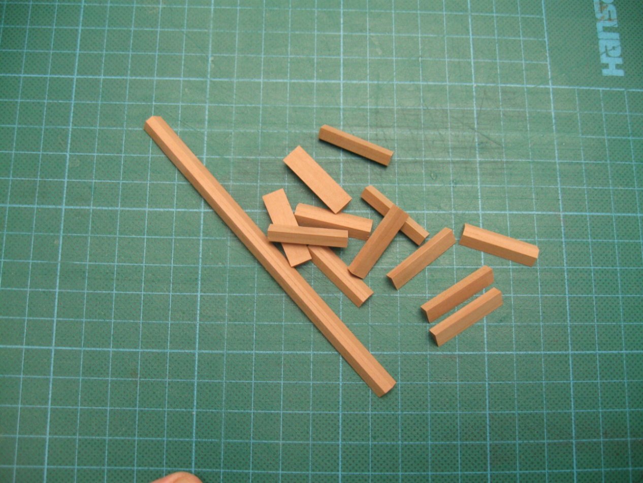
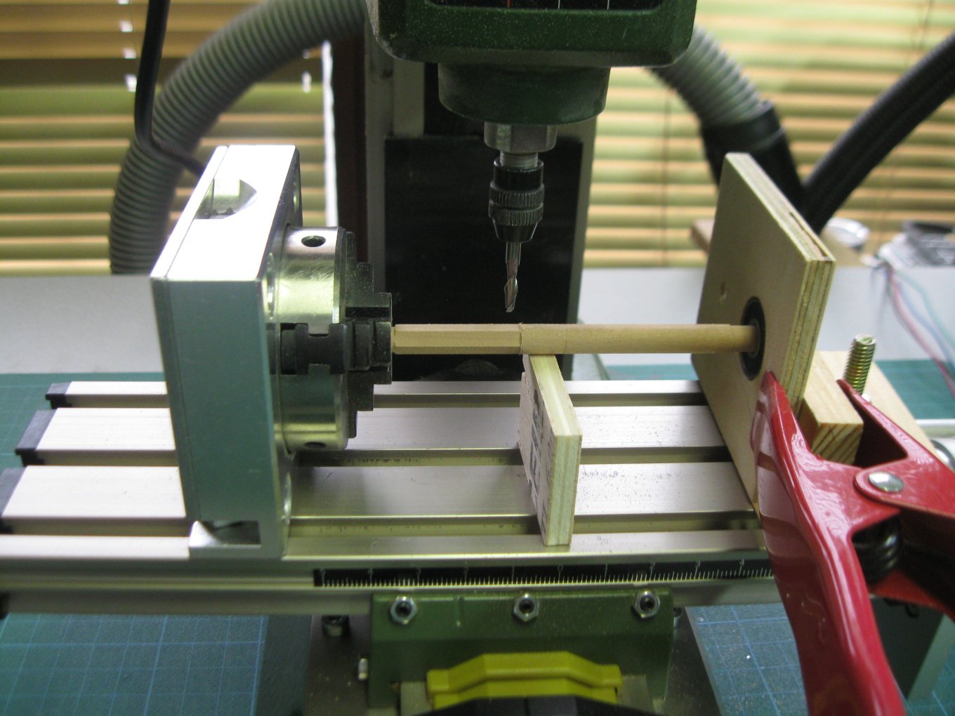
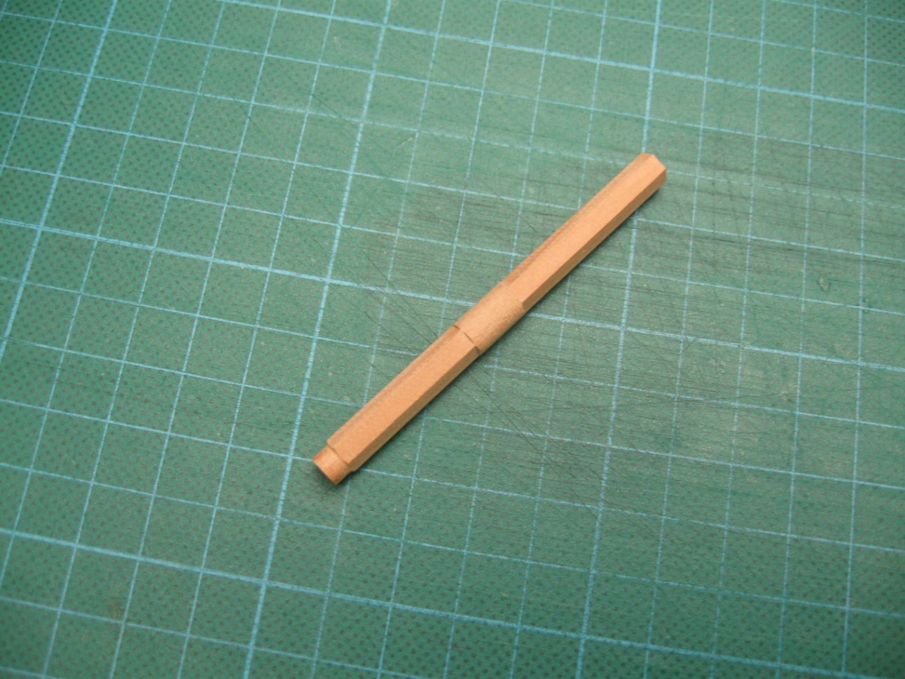
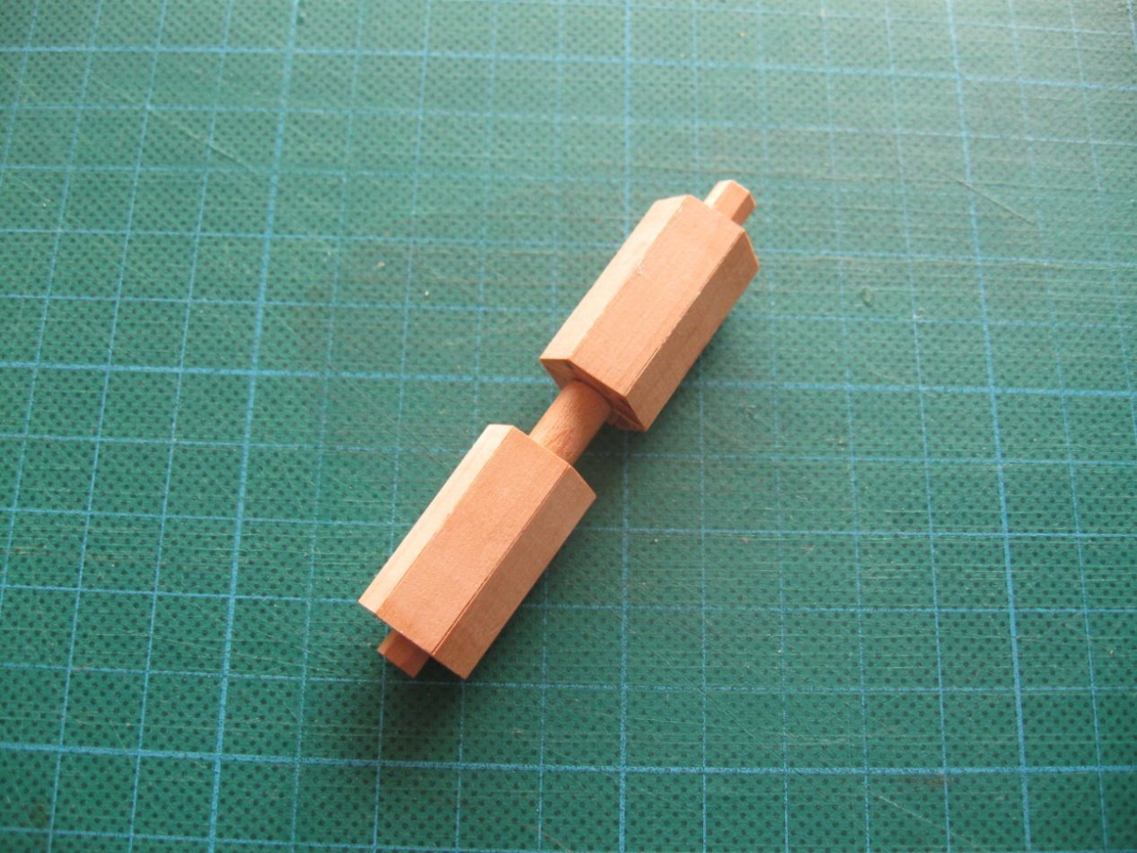
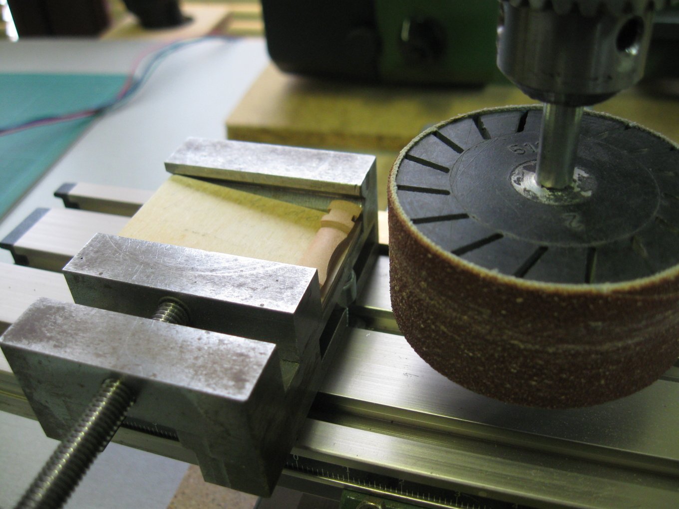
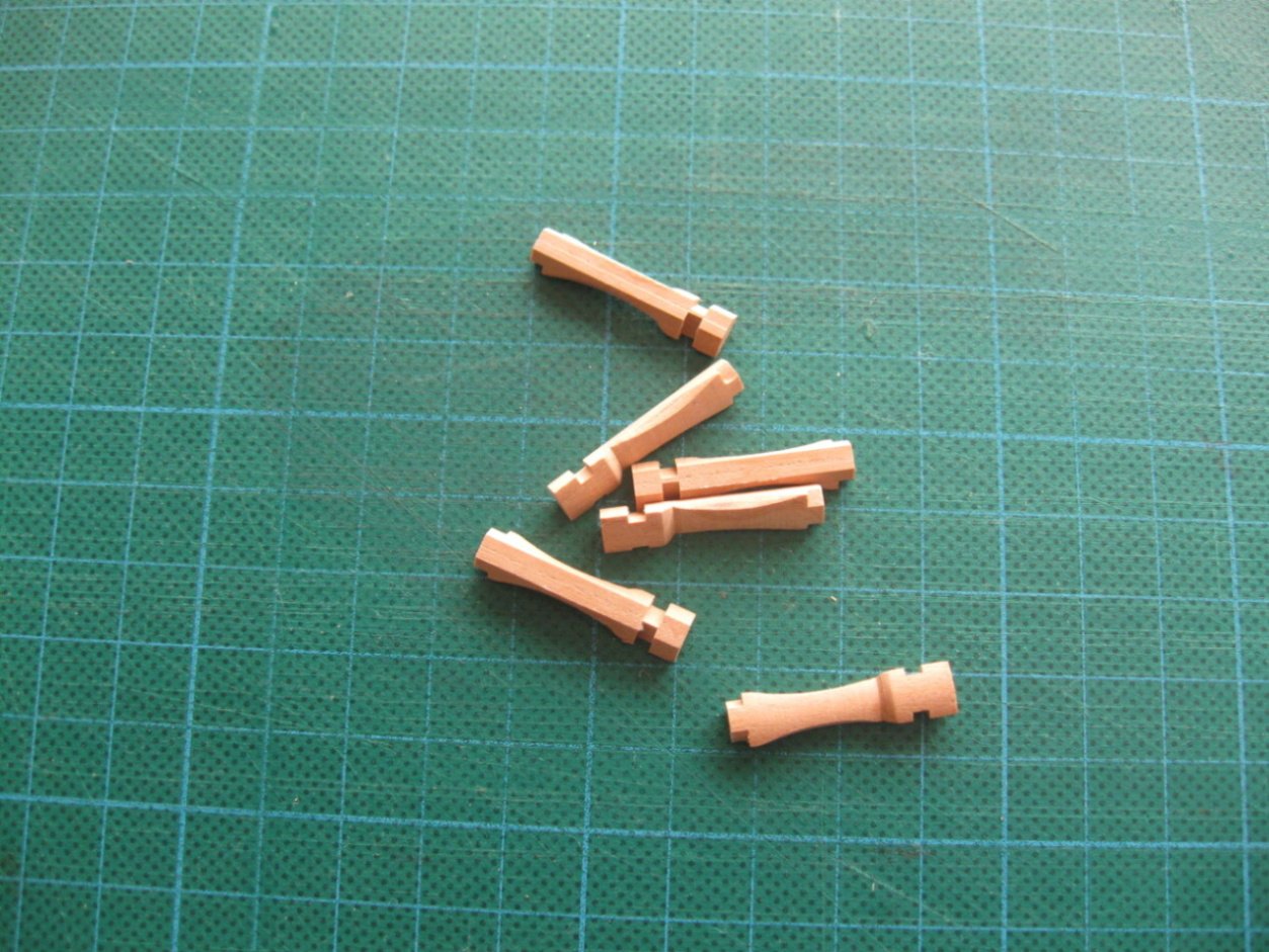
I am starting work on main capstan parts - some pictures from production.
Thank you Marsalv. The machines that we use will always be controversial but then again as you said, they will be just another evolutionary step, sort of like when I purchased a mill for my self. As far as what tool's you use, be that a set of carving tools or Cnc doesn't matter, both takes a lot of work and skill to achieve what you have shown us. One last question Marsalv, but what tool bits did you use when you did you cnc carvings, a self made set or a set that one can purchase to do the carving's? I am getting in to CNC, something that I should of done years ago and knowing what the right set of tool bit's that one needs for miniature carving in cnc will really help. I have been looking but so far have come up empty finding a set. Look forward in hearing from you. Keep up the outstanding building your doing and thank you. Have you ever thought about doing a a tutorial on Miniature cavings in cnc? Just might be what some of us need to help us grow. Gary
-
-
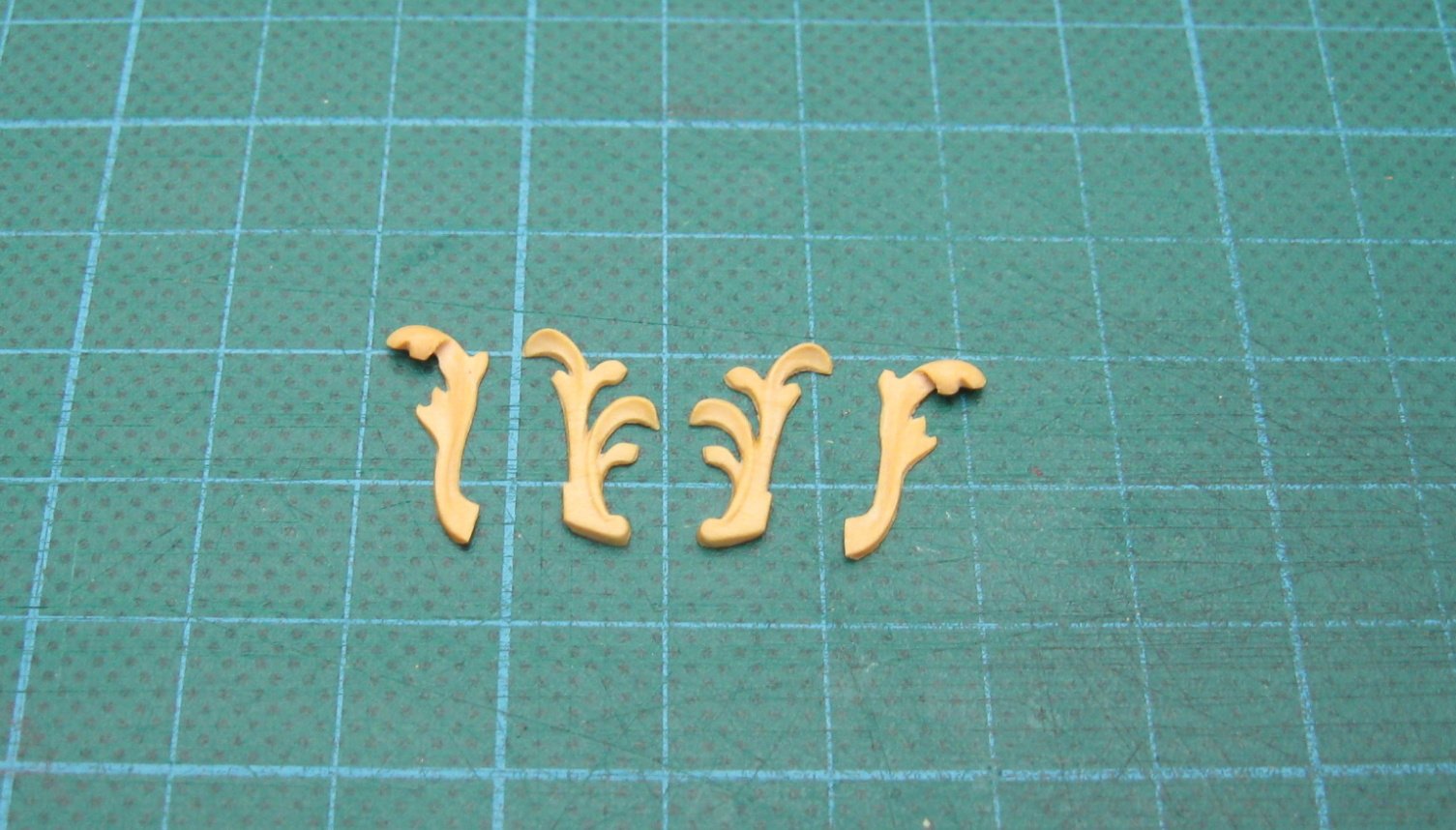
On 1/29/2021 at 5:26 AM, marsalv said:
To PeteB: I used the black translucent paper for the caulking.
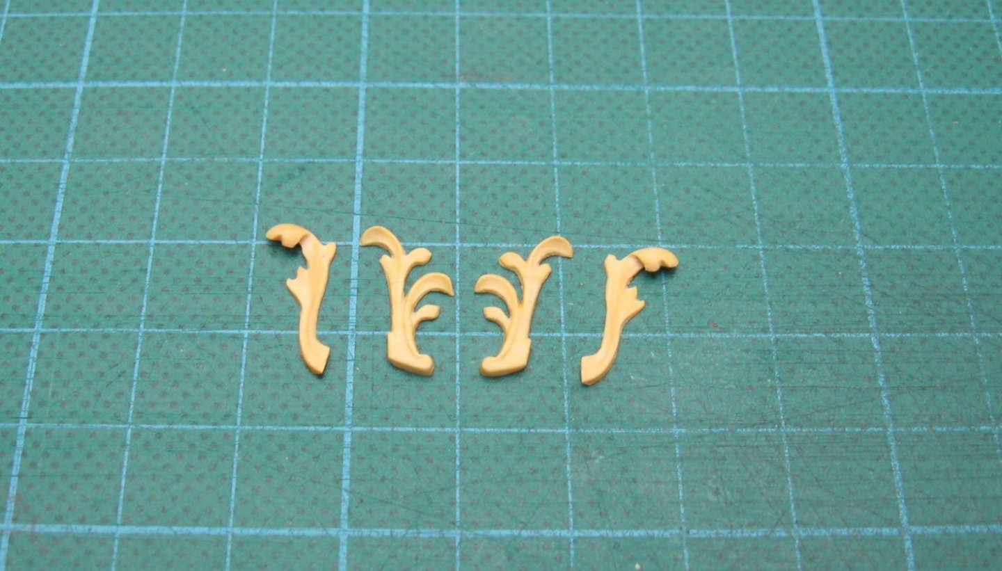
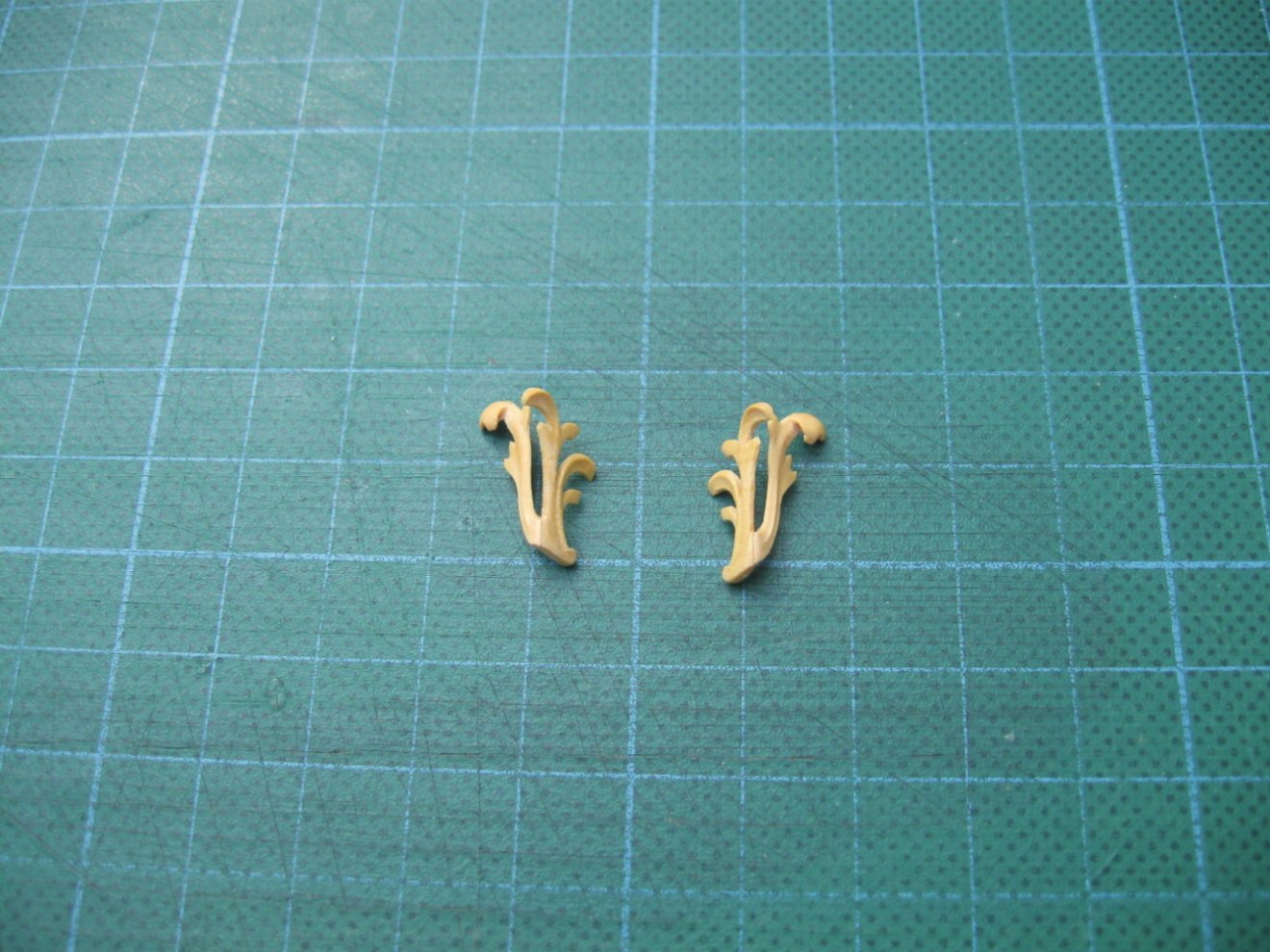
The last stem decorations are added. All carvings are made with CNC milling maschine with small manual corrections.

Hi Marsalv. Have a question for you. What program are you using for doing your carvings? I just may purchase the same one. At the moment am looking at V Carving which might be the route for me to go. Thank you and keep up the outstanding work. Gary
- JOUFF, EricWilliamMarshall, mtaylor and 2 others
-
5
-
Thanks druxey and you may be right. I did take a look in Boudriot 74 gun ship vol 4, page 74 and it shows the exact same set up that I believe was common for are era. Seems that the messenger just went around the front of the bow sprint and was just helped along with the crew with no rollers in the manger. Apparently both the French and English were using the same set up during our time frame. He did say that they had pillars/rollers placed out far enough from the center line to keep the messenger from rubbing up against the pumps and other items. Did the English use rollers along the side, maybe, maybe not, can't find any thing until1792. Probably won't really ever know but when I finally get to installing the pillars I just may get a answer for myself.


Harold Hahn method
in Building, Framing, Planking and plating a ships hull and deck
Posted
Hi Mark. Sounds like one building a model tank, build it with the guts or just build it as a hull. Lets us have a choice. I much prefere to build it with the guts. To me much more interesting even if I can't see the inside. At least I know it's there. Gary