Hubac's Historian
-
Posts
3,314 -
Joined
-
Last visited
Content Type
Profiles
Forums
Gallery
Events
Everything posted by Hubac's Historian
-

MONTAÑES by Amalio
Hubac's Historian replied to Amalio's topic in - Build logs for subjects built 1751 - 1800
The work, here, is better than full-size practice. -
Certainly, from a practical standpoint, you are right, EJ. Everything I’ve seen, though, seems to show that function followed form, here. I’m not sure who’s framing diagram this is - it’s probably Michel Saunier’s - but I think it’s a pretty good rule of thumb on this particular design issue.

-
I am going to tap lightly on the brakes here, EJ, to say that I think the outboard face of the stern balconies should run parallel with the angle of the stern; the balconies, themselves, should rake aft, as opposed to plumb with the waterline. I don’t think this would be a major fix, as you could salvage the entire aft face and just re-make the sides. I raise the flag, here, because the inconsistency is visually jarring.
-
My gut says to go as tall as I can within the accepted ranges of R.C. Anderson and the actual surveyed dimensions of SR, as tabulated by Michel Saunier. There is some sense of plausibility in that, which also satisfies my aesthetic sense for what I want my model to look like.
- 2,699 replies
-
- 3
-

-
- heller
- soleil royal
- (and 9 more)
-
Hey BW! Thanks for stopping in and sharing your thoughts. In fact, you have very much hit the nail on the head. A reconcilliation of primary, secondary and tertiary sources is exactly what I am up to. There are the primary sources that involve the ship, herself; these are the Berain drawings, the VDV, Monamy, and Bakhuizen portraits of her. The secondary sources include contemporary portraiture of other French ships that were contemporaries of SR - those by the VDVs are the best and most detailed. Tertiary sources include portraits of other nation’s great ships that were contemporaries of SR, as well as other people’s modern models of her, and all that I can find that has been written of her history. At best, and considering all of these fragments, looking at the first SR as she might have been after her re-fit, is sort of like trying to discern the shape and magnificence of her through a dense fog; there’s something quite majestic there, glinting with gold and bristling with arttllery, but the picture is just so slightly out of focus. This is why the painting of SR (port quarter view) facing off against Britannia, at Barfleur, is so captivating. There is something truly meaningfull, there, to be gleaned - if I could only just find the current whereabouts of the painting for a better look: The height of her rig; the breadth of her hull; the configuration of her stern and quarters with all of Berain’s allegorical intent; it’s all, there. I can just make out the outline of it. Almost... But, as I said in an earlier post, it is an effort to strike a balance between artistic interpretation and what is actually known and recorded about this early period in pre-plans naval architecture. And, to do all of that within, and to some degree to stretch, the apparent limitations of the Heller kit. Opinions are just that, but in mine SR was a ship that was so far beyond any of her contemporaries, in terms of her grandeur, and the epic performance of Tourville and his crew at Barfleur. The subject never bores me.
- 2,699 replies
-
- 6
-
-
- heller
- soleil royal
- (and 9 more)
-
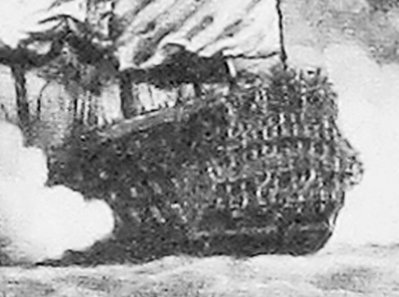
Leafing through the Fox book, yet again, looking for exactly this kind of evidence of long lower masts: Here’s another VDV, the Elder, drawing from the cover inset. It shows a number of British First rates laid up, in ordinary on the Medway in 1685. This is only one half of the portrait (the oher half is at the book end paper), but I think it is fairly illustrative of the point.
- 2,699 replies
-
- 4
-
-
- heller
- soleil royal
- (and 9 more)
-
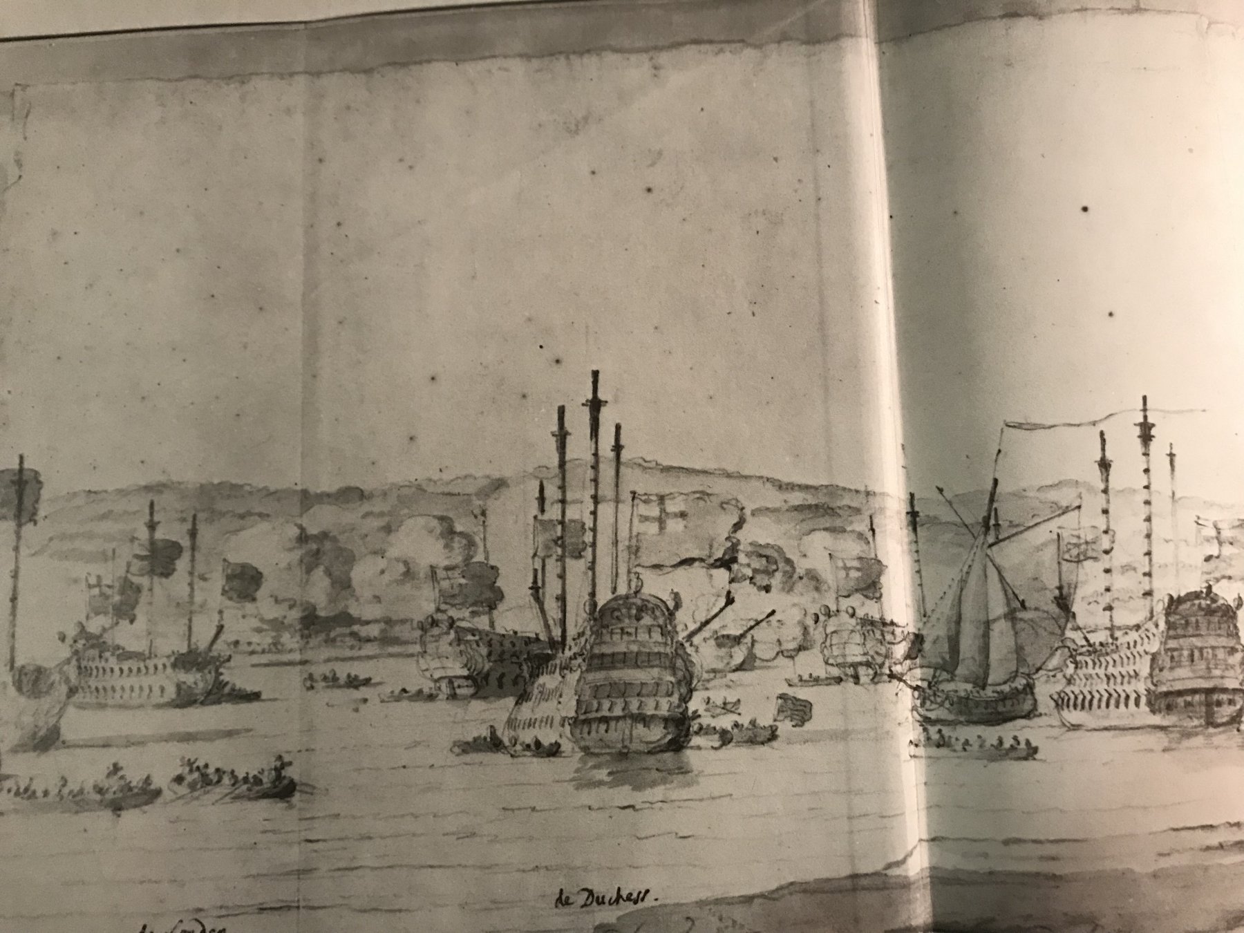
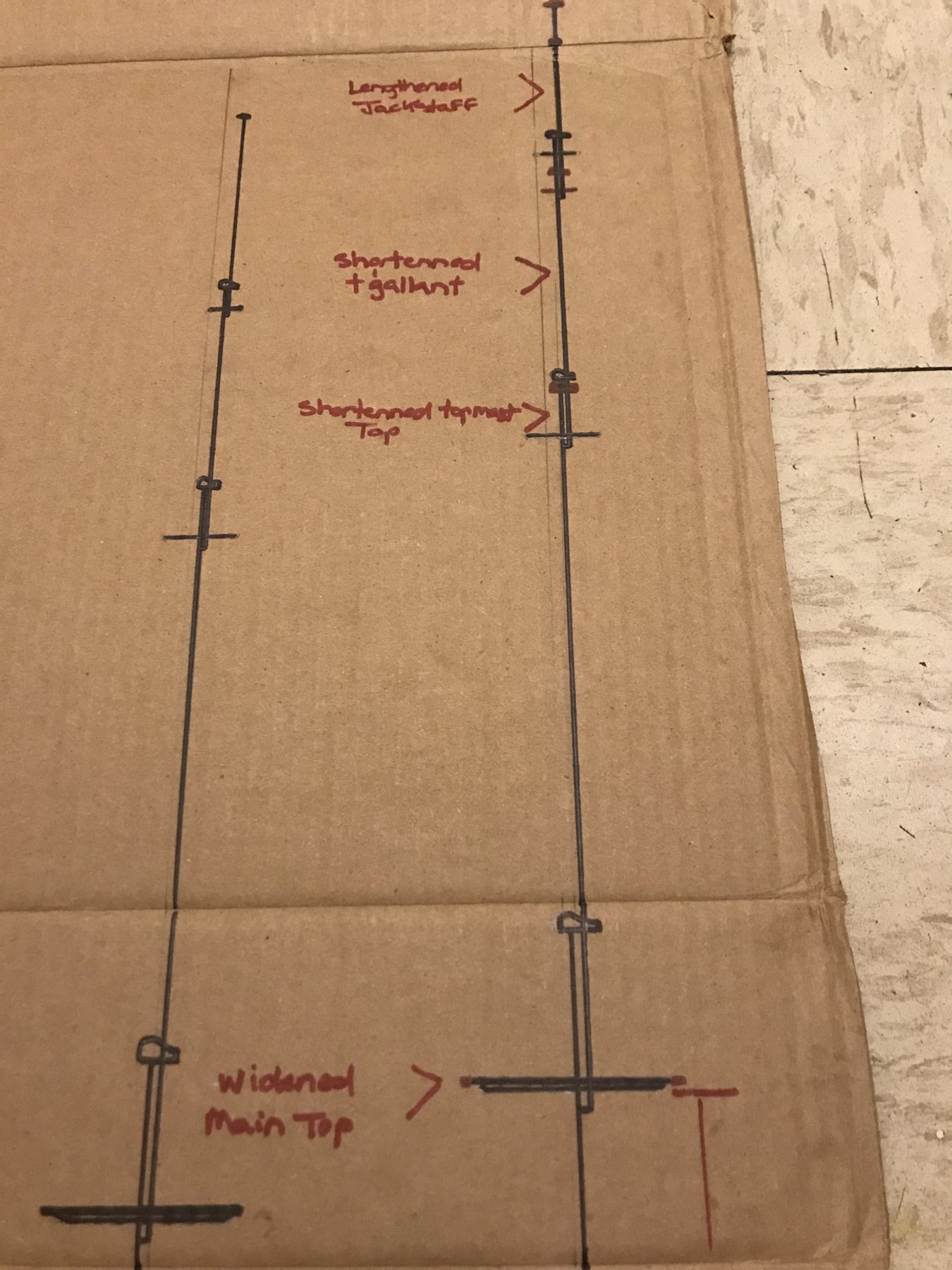
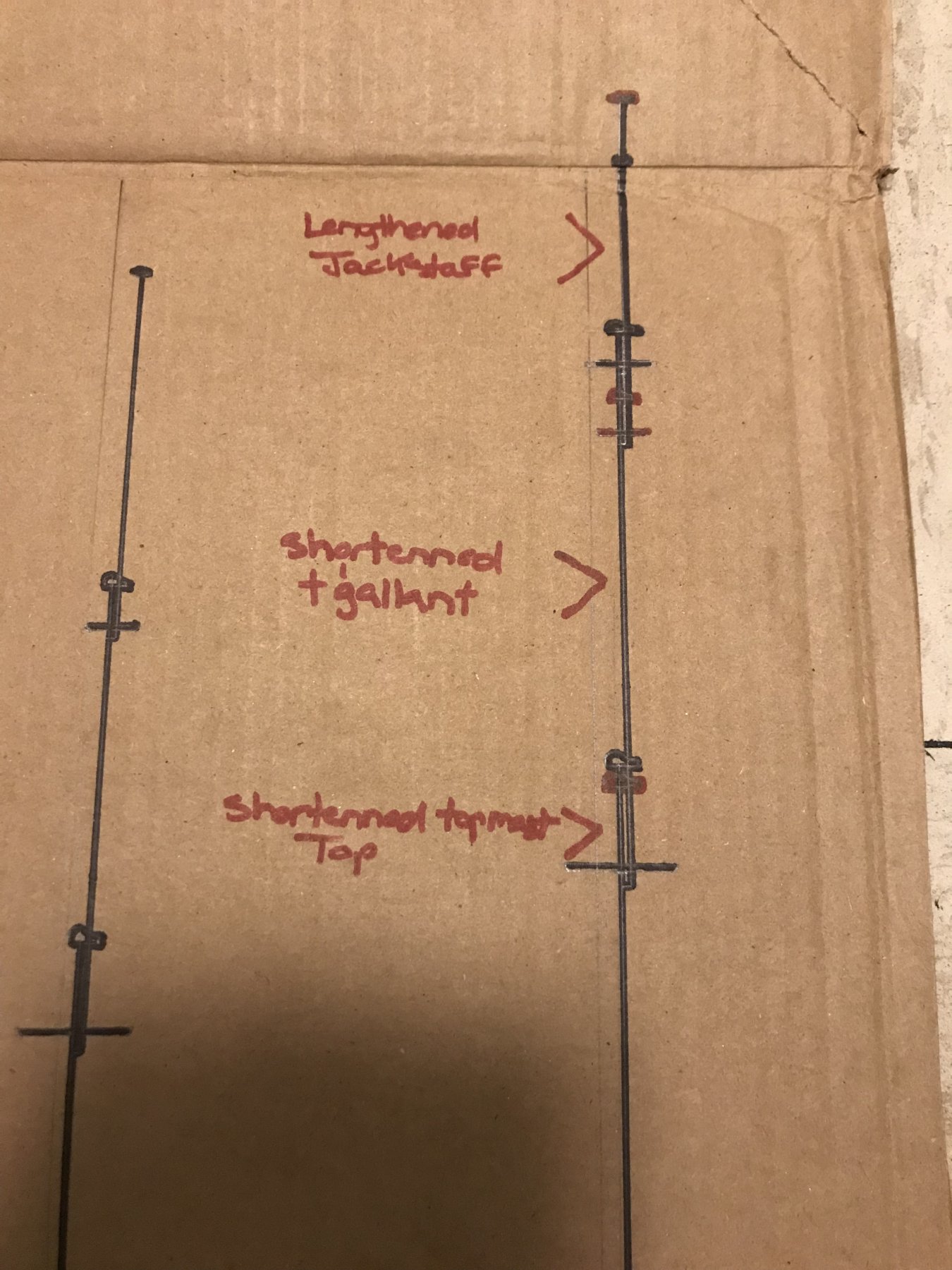
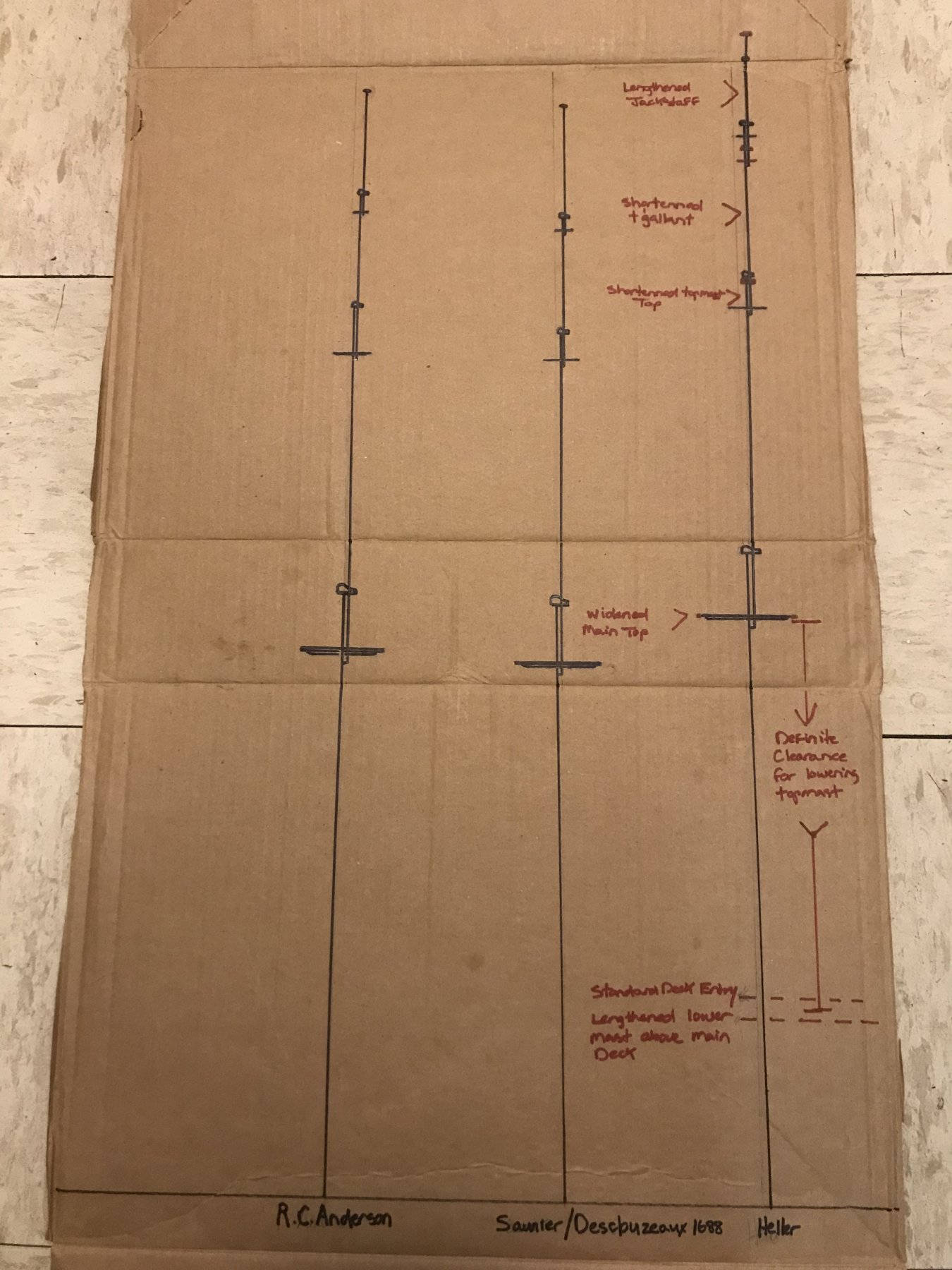
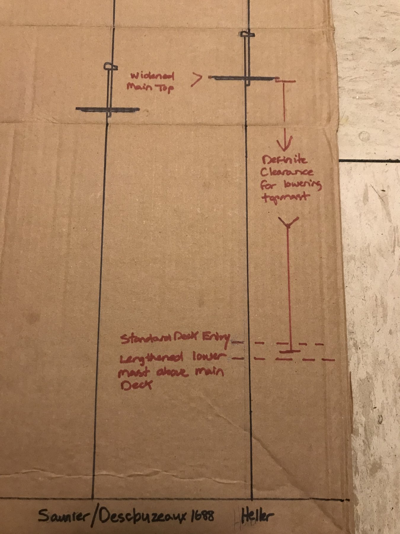
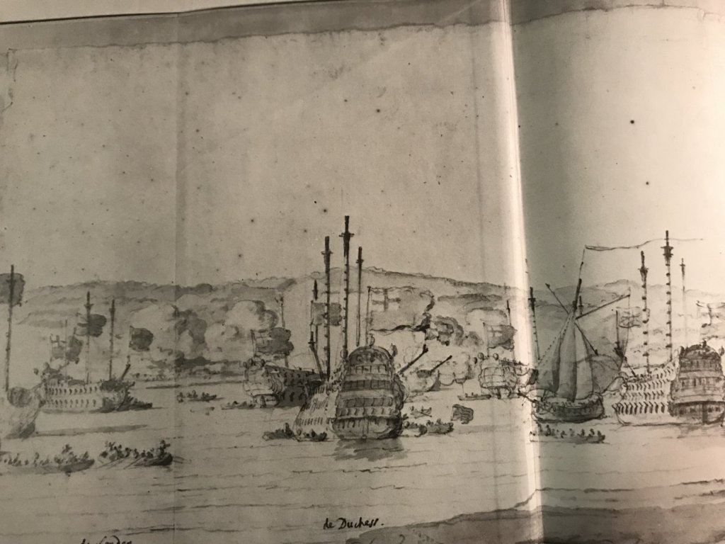
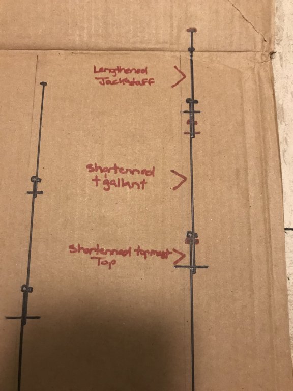
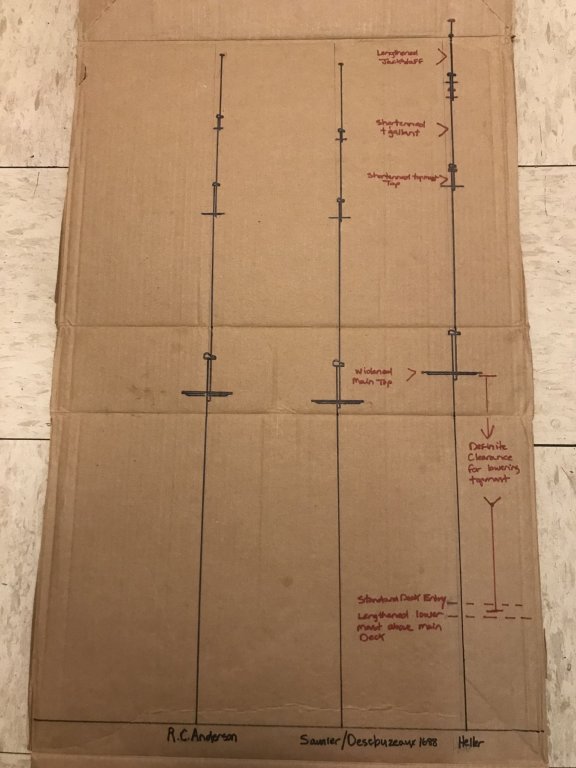
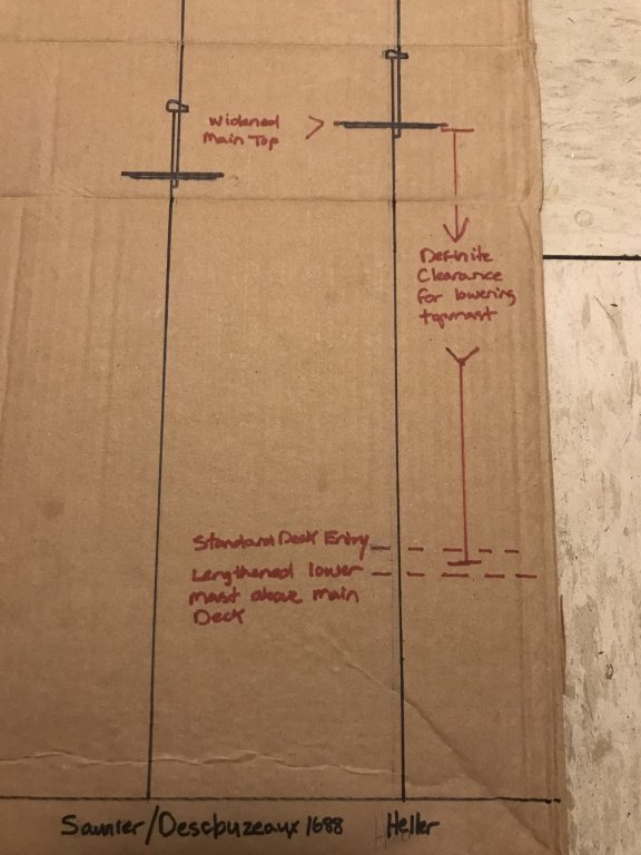
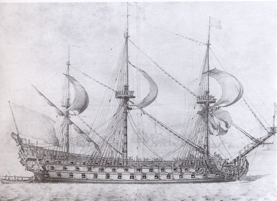
Thank you Dafi and EJ, for your likes and especially for your thoughts and comments! When I got home last night, I took out my copy of The Great Ships (referenced above) because, in the chapter dedicated to the French navy, there is a decent-sized re-print of this portrait of Royal Louis. Just for fun - because this is how I amuse myself - I took out my steel ruler and measured the width of the main top, as printed on the page; 1/2”, exactly. Then, I measured up the main topmast from heel to mastcap; 1 11/16” (as I remember, but I was doing this quickly as I waited for my daughter to get ready to leave the apartment) on the printed page. Then, I divided the theoretical dimension of my topmast, full size (74’) by the diameter of my widened main top (19 1/2’) and the result was 3.79 - which very nearly corresponds with my measurement test of the Royal Louis on paper. Granted - there are obvious perspective issues of the artist who drew the portrait of RL; distance from the subject, and a foreshortening of the mast height, depending upon his vantage point. As a quick cross-check, though, this is a pretty decent guage. To my eye - this looks right. So, without further delay, here is my line diagram of the three different mast layouts: To the far left is R.C. Anderson. Michel Saunier’s dimensions as taken from the survey of the ship in 1688 by Desclouzeaux. NOTE: for Michel’s mast I merely added a longer jackstaff because, if the dimension for this item exists in his table, I could not translate what that might be. And to the right are the stock, Heller dimensions, with my alterations noted in red. It’s all a little muddled, but it gives me a good enough idea so that I can mock up the main mast, eventually, to see what it really looks like. Also... Here is a nice Puget sketch of a French warship that shows the relative heights of the lower masts, and gives some sense for the slight rake of the main and mizzen masts: https://pin.it/yr66kyqp4vzq5a I try as much as I can, with this build, to respect the scale of known equipment and furniture of a ship from this time. On the other hand, I find it useful to balance that with the artistic eye for the lesser known/recorded grey areas. This is why I include so much contemporary portraiture and sketches. Though they are often quick gesture sketches, these were masters of their craft and extremely familiar with their subject. I have little doubt that they are capturing the feeling of the vessels they are portraying. Here is a quick sketch of the disaster at La Hogue by the younger VDV. There is no way of knowing whether the main subject is SR - probably isn’t for a few reasons, chiefly among them, that it looks more like a second rate, rather than a first - but I include the image because it shows relatively tall lower masts. https://pin.it/fjx7zxwlbnxhzi I don’t know why I can’t edit out this duplicate picture of my mast layouts, but this site is funny like that sometimes, so here it is again


- 2,699 replies
-
- 5
-
-
- heller
- soleil royal
- (and 9 more)
-
While it is absolutely true that I haven’t even assembled a hull, yet, I am already beginning to work out the primary proportions of my main mast - from which the fore and mizzenmast will be derived, per R.C. Anderson. To begin with, there are a number of scale issues with the kit-supplied masts and spars. The issue most often cited by builders of this kit is what appears to be overly long main and fore topmasts. Interestingly, the length of the Heller fore topmast is actually about one scale foot (or an 1/8”) longer than the main topmast. However, when applying R.C. Anderson’s guidelines for French practice after 1670 (.66 of the lower mast), one arrives at a scale dimension that is just slightly longer than Heller’s main topmast - to the tune of 1 1/2’ in full size , or 3/16” in scale. For fun, I converted the survey dimensions that Michel Saunier provided me (from the 1688 survey of SR before her refit), and I arrived at a main topmast dimension that is slightly shorter than the Heller dimension - by 1/4”, or two scale feet. So, I don’t think the topmasts are really the biggest scale issue. Also, my observation of all of the better contrmporary portraiture of French ships bears this out: topmasts were quite long. What I find most out of proportion are the t’gallant masts. Using Anderson’s metric, one arrives at a t’gallant of 4 3/4”, Saunier gives you 4 1/4”, the Heller kit, though, has a main t’gallant of 5 13/32”. All of these dimensions, by the way, are from the heal of the top/t’gallant mast to just beneath their respective mastcap. The other interesting consideration - especially considering the rather shallow draft of the Heller hull - is the scale length of the lower masts, from footing to beneath the cap. Anderson’s mast comes in at 14 5/16”, Saunier at 14”, but Heller comes in at 15 1/8” scale! This actually works to my advantage, and I will explain why in a moment. The general sense of the thing that I am trying to acheive can be seen, here, in this portrait of the Royal Louis. Previously, I had seen this drawing dated to 1668, but then, more recently I’ve seen the year 1688, attributed to the drawing - which because of the style of quarter gallery and headrails, actually makes more sense: My plan for the main mast is, thus: For the first step of the mast, I may actually increase the distance from the main deck to the top of the cheeks by 1/2”. I will do so, if I see in my eventual mock-up that a fairlead for the main shrouds necessitates this increase; remember, I am lowering the channels to the main deck level, and also increasing the width across the beam by what amounts to 5 scale feet. While this would be an alteration that makes my build work - and, perhaps, not wholly accurate to late 17th C. practice - I don’t think the appearance of the model will suffer from the added height. In fact, doing so, would erase any doubt that the topmast could be lowered without hitting the main deck. I will maintain the length of Heller’s main topmast (9 1/4”), as it falls very neatly between Anderson (9 7/16”) and Saunier (9”). the biggest alteration will be to the t'gallant. I will shorten this mast from 5 13/32” to Anderson’s length of 4 3/4”. I will then take that lost height and add it back to the jackstaff, which on the Heller kit is simply too stubby. Anderson allows for some leeway, here, but I may increase the jackstaff from Heller’s 2 11/32” up to something on the order of 3 5/8”. In my line drawings, so far (which I will post, once I’ve darkened them with marker), the effect of these changes is pleasing to my eye. One thing to note: using Anderson’s ratio’s for arriving at the main topmast head (1/10 of the lower mast) yeilds a dimension that just looks exagerated, whereas Saunier yields a much more reasonable 7/16”. The other significant scale issue is that of the main and topmast tops. The topmast tops are grossly too big and need to be reduced to something more in line with Anderson. The style of the topmast tops also, as far as I can tell, reflects 18th century practice, and not 17th C. To my eye, though, the scale of the main top is too small for the ship. The spread of the topmast shrouds would be greatly improved by an increase in diameter. As is, the Heller main top measures 2 3/16”, which translates to 17 1/2’ in full-size. On the surface of things that seems fairly enormous! It just so happens that, today, I was laying down metal track for a knee wall that measured exactly 17 1/2’. Huge! My 1/4” scale addition would increase my top diameter to what would be 19 1/2’ in full practice. Seems improbable, I know, but remember that I am increasing the breadth of beam by 5’. Whatever imbalance this top increase might introduce in the standard kit, will be more than absorbed by my increase in beam. Now, take a closer look at the main top of the Royal Louis, above. Though it’s a little fuzzy behind the shrouds, there appear to be 8-9 men standing across the diameter of the top, with a little room to spare between them. If you figure that the average body occupies around 2’ of shoulder room, a top platform in the 18-20’ range of diameter may not be so unreasonable after all. My conclusion from all of this is that the scale of these warships must have been truly enormous. The sum total of all of these dimensional changes to my main mast will yeild a mast height above the main deck of 25 1/4”. I will post the line drawing later, which will illustrate these differences more clearly.
- 2,699 replies
-
- 4
-
-
- heller
- soleil royal
- (and 9 more)
-
Aha! Thanks, Druxey! So, this would be one aspect of this model presentation that makes it a diorama. Cool.
-
General question here: often on the admiralty models, we see these narrow strakes, running from stem to stern. They aren’t wales, and their run (as seen very clearly on this model) doesn’t even correspond with the run of the planking. So, I wonder what specific purpose they serve on the model. On this model of the Bellona, they are even shown running between planking strakes of the upper works. Was their sole purpose to illustrate the fairness of the frames and the shape of the hull for the admiralty board?
-
Wow Gary! Another really excellent 74, and a wry sense of humor to go with it. I’ll be following your Alfred with enthusiasm. It continually amazes me, on this site, the many talents and accomplishments of other modelers. Great work, so far! - Marc
-
Hi Mike, I think your instinct to lower the seat for the figurehead is the correct approach. If the angle of the bowsprit is within range, and the scrolled end of head rails terminates where it is supposed to beneath the bowsprit - then lowering the seating of the figurehead shouldn’t interfere with anything else.
-
Your planking is superbly done, Don. In all honesty, though, I don’t love the look of the finished beech. Just my personal preference. It’s a shame to cover the planking, but I think that might be the best presentation.
-
Incredible model and just an awesome sail-making tutorial! This is such a great example of how much better these Heller kits can be made through research and effort. Great job!
- 126 replies
-
- 1
-
-
- le superbe
- heller
- (and 2 more)
-
Every complimentary thing, everyone else has said - me too!
-
Wow! This looks like a superb and clean build. The fairing of your lines is excellent! I will be following along. All the best, Marc
-
Thank you, EJ! Although, I have to say that the standard-bearer for plastic ship-modeling has to be Dafi, with his Heller Victory; he just takes it up several notches! I appreciate the compliment, though. As with you, my primary motivation for starting a build log, in the first place, was that I wanted a place to compile research and references for a future scratch-build for which I won’t have to make compromises. I remain hopeful that this collaborative monograph of a 90-gun ship of the Second Marine will come to press sometime soon. I believe that this work will shed additional light on many of the practicalities of French naval architecture from this time period, and just before. It seems likely that much of what Mr. Lemineur and Mr. Tusset are laying forth in this model would certainly have been applicable, just a few years earlier in 1688/89. Taken together with the monograph on L’Ambiteaux, and guided by the survey dimensions of 1688, I think that one could arrive at a very good hull form as the basis for a model of Soleil Royal. Only time will tell, though.
- 2,699 replies
-
- 2
-
-
- heller
- soleil royal
- (and 9 more)
-
Thanks, Don! I really appreciate that you have stuck with this slow-moving monster from the beginning. Your encouragement helps keep the lights on, down the long corridors of a project like this.
- 2,699 replies
-
- 2
-
-
- heller
- soleil royal
- (and 9 more)
-
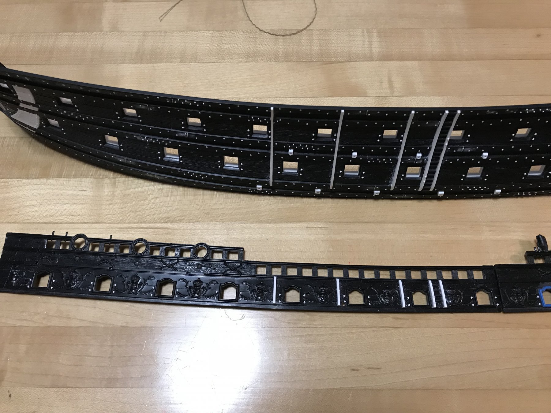
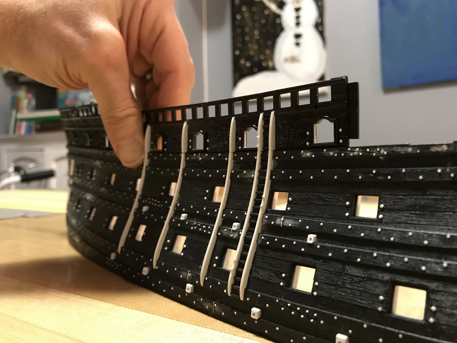
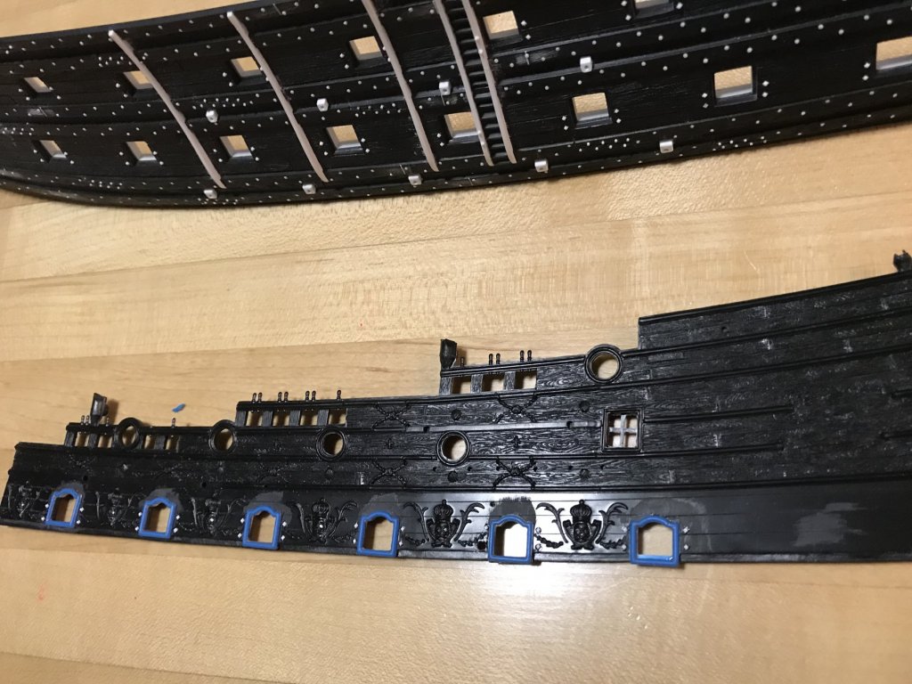
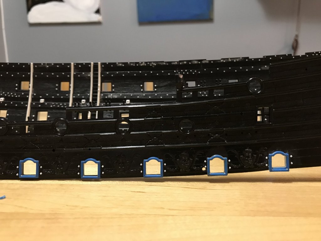
Thank you very much, Mike, for your kind words. I really appreciate your taking the time to read through my log. I am nothing, if not verbose! As a matter of fact, I am drafting an intro to something. Probably not a book, per se, but maybe a solid pre-amble to this entire build-log, which I will eventually edit more thoroughly. This pre-amble is tentatively titled The Gilded Lilly: A Meditative Reconstruction of Laurent Hubac’s Post-Refit Soleil Royal of 1689. Verbose . Owing largely to the flawed nature of the Heller kit, my attempts to modify it have drawn the attention of many of the best scholars of the epoch, and of the ship, herself; J.C. Lemineur, Gerard Delacroix, Andrew Peters (I wrote to him, really, but he was very helpful), Michel Saunier, Marc Yeu (AKA Neko), Cedric LieGeois, Dan Pariser and a host of other MSW contributors who have been instrumental in helping me to understand my own assumptions and misconceptions about the ship. Whether the model succeeds or fails, it has been so gratifying for me to see the ship debated, and to see the particularly excellent work of Michel Saunier, Marc Yeu and Cedric LieGeois find it’s way onto MSW. As for my model, I stake no claim to be a serious scholar, myself, or to have any definitive conclusions about her appearance. But I do spend quite a lot of time thinking, even in a meditative and subconscious sense, about how to reconcile all of this information - the Berain drawings, the VDV portraits of her contemporaries and the body of modern scholarship into one coherent picture of what might have been. It is, I hope, a plausible theory that will spark continued debate and more efforts to model the ship. In the end, though, what I am essentially attempting is to see how closely I can modify this flawed Heller kit into a plastic approximation of Marc Yeu’s excellent scratch-built model. Speaking of Marc, I decided, after all, to grind away and re-position the aft-most main deck port, on the port side: Here is the port re-positioned. Because I haven’t faired the inner, lower sill yet, you can just see the heavy 1/32” difference from where the port was, originally. I am pleased with the alteration, but I won’t bother to do the same on the starboard side because the discrepancy is so slight as to not warrant the change. Here, though, it was noticeable, and I thank Marc for speaking up. The second wave of detailing is well underway. In the following pictures, you can see that I have been busy adding the gun carriage through bolts and the top sections to the skids. The latter presented some challenges in getting the upper bulwark pieces to properly align with my main reference point - the waist ladder. One difficulty was leveling a clear path for the skid extension pieces, where they crossed the acanthus escutcheon ornaments. Patience, and careful sighting of the line, with the upper bulwark in position, showed me what to cut away. A little putty will be required at the joints (I was a little overzealous in fairing the second skid, in particular), but overall the fit and alignment are quite good. The other thing that I thought was worth attempting was to scribe plank lines into the smooth plastic between the main deck ports: For this, I simply made a styrene pattern of the lower edge of both the fore and aft upper bulwarks, and then working from the bottom edge up, I carefully scribed in plank seams from fore to aft. I did not attempt to scribe one whole course, at a time, because my pattern had to rest upon the raised port frames and it was impossible to maintain position for a fair run. Instead, I scribed a series of lines, between ports, from bottom to top, and then connected the dots from one port to the next, working aft. This seemed to work well. As I approached the top, though, the discrepancy that Heller moulded into the plastic became more apparent, and my plank scribes reflect this; what I’m referring to is the available space between the top wale of the lower hull and the next sheer strake of the upper bulwark. This space is slightly narrower at the extreme ends, and bellies in the waist. As this discrepancy was consistent with the lower gun decks, and the way that the scribed plank lines were sometimes interrupted by the sheer of the wales, I decided to just continue with the same scribe pattern. The area on the upper bulwarks, where this difference will be most apparent, will be mostly covered by the quarter galleries, anyway. To my way of thinking about it, adding the plank seams makes the model seem a little less “plastic,” which is always my goal with this build. Going forward, I will complete all the through-bolting on the starboard side, thin and detail the plank edge of the beakhead bulkhead, and add the stern extension of the upper bulwark. Following that, I’ll carve resin mould masters for my main deck port frame enhancements. That first foray into casting will provide me the necessary experience for tackling the ornamental frieze elements.


- 2,699 replies
-
- 7
-
-
- heller
- soleil royal
- (and 9 more)
-
As always, Marc, your perception is spot-on! I have taken a closer look, and you are definitely right. I will sit on this for a “minute.” When I sight the run of the ports from aft, forward, or visa versa, this discrepancy is there, but not hugely apparent. I may fix it, or I may not. This is one of those things about the Heller kit; this particular port was incorporated into the stock quarter gallery, so that the port frame was a coved, moulded frame that overlaid the rough opening. I have the extra frames, so I will see how I feel about it tomorrow. I’m looking forward to seeing what progress you have made on your ship, Marc. Hopefully, your work situation will settle sooner than later. And a happy 2018 to you and your family!
- 2,699 replies
-
- 2
-
-
- heller
- soleil royal
- (and 9 more)
-
MONTAÑES by Amalio
Hubac's Historian replied to Amalio's topic in - Build logs for subjects built 1751 - 1800
Amalio, your work here rivals anything ever accomplished in full-size. This is just one of the most remarkable models I have ever seen. Really enjoying watching this one take shape. -
Thanks, Henry, for the quick reply. You have corroborated what I have found in my own reading, regarding the main and fore sheets. On Dan Pariser’s Queen Anne’s Revenge, he incorporated sheaved fair leads into his bulwarks, but that ship is a little bit later - around 1710. I know what you are referring to on Michel’s SR. I’m not sure about whether that was a common practice for the time, on the beakhead bulkhead; no idea, really. From a mechanical advantage standpoint, it makes perfect sense. I have, however, seen a similar belaying station between knight heads, aft of the main and fore masts. Maybe also on Dan’s QAR. I can’t remember clearly, but a little later I’ll reference his log to see what I find.
- 196 replies
-
- 2
-
-
- plastic
- soleil royal
- (and 2 more)
-
Hi Henry, Lately, I have been thinking a lot about the issues of sheets and tacks as I begin detailing my upper bulwarks. I thought I would come visit your log again because I remember that you were grappling with the fair-leads on these, earlier in the log. I definitely agree with you about not attaching the main brace to the flagstaff. I really like your work-arounds for the spritsail sheet, Main sheet and fore brace. I was thinking, though, that I might incorporate a sheaved block for the main sheet, that then enters the main deck upper bulwark, just forward of the QG. Perhaps a similar scenario could be employed on the fore sheet? The thing I was trying to ascertain, though, was whether the practice of incorporating a sheet sheeve directly into the timbers of the upper bulwarks, was a practice observed by the French before 1692. Any advice there? I've also been thinking about belaying pins. No matter what, I will be shaving off the moulded belaying pins (because I've already broken off a number of them, anyway) and replacing them with brass. In your research, would you agree that the use of pin rails did not really come into widespread use, by the French, until later in the 18th Century? Would you say that this practice of tying off to the sheer rail is accurate and appropriate for the time period? At the moment, I'm working through Anderson, trying to figure out my mast and spar dimensions. That has been interesting, to say the least! I've said it before, but your rigging work is really awesome! I marvel at your ability to re-create full-scale practice in 1/100 scale.
- 196 replies
-
- 2
-
-
- plastic
- soleil royal
- (and 2 more)
-
Roter Löwe 1597 by Ondras71
Hubac's Historian replied to Ondras71's topic in - Build logs for subjects built 1501 - 1750
This looks to be a truly fascinating and instructive build. You are making a very neat job of it, so far, and I will be following along with great interest. I loved your router table technique for cutting the rabbet into the stem!