


drobinson02199
-
Posts
919 -
Joined
-
Last visited
Content Type
Profiles
Forums
Gallery
Events
Posts posted by drobinson02199
-
-
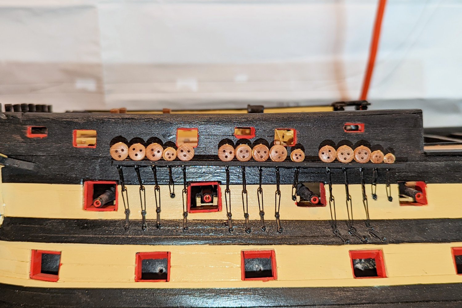
Since my last post about 10 days ago, I've been working on the channels, deadeyes and chainplate. I started on my "learning side" and did come up a learning curve in terms of how to get the chainplate much better aligned. It took a while to get both sides done. Here are some pictures.
Regards,
David

- ccoyle, src, mort stoll and 5 others
-
 8
8
-
-
-
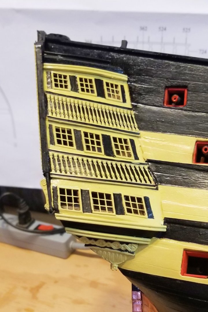
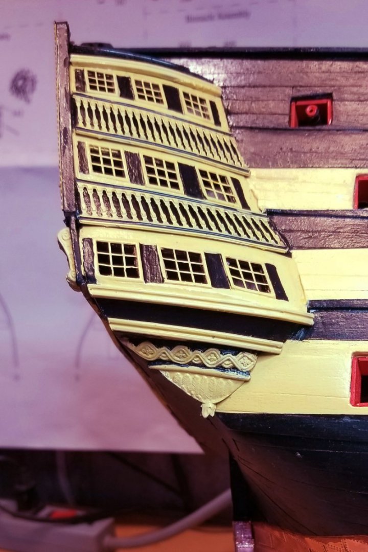
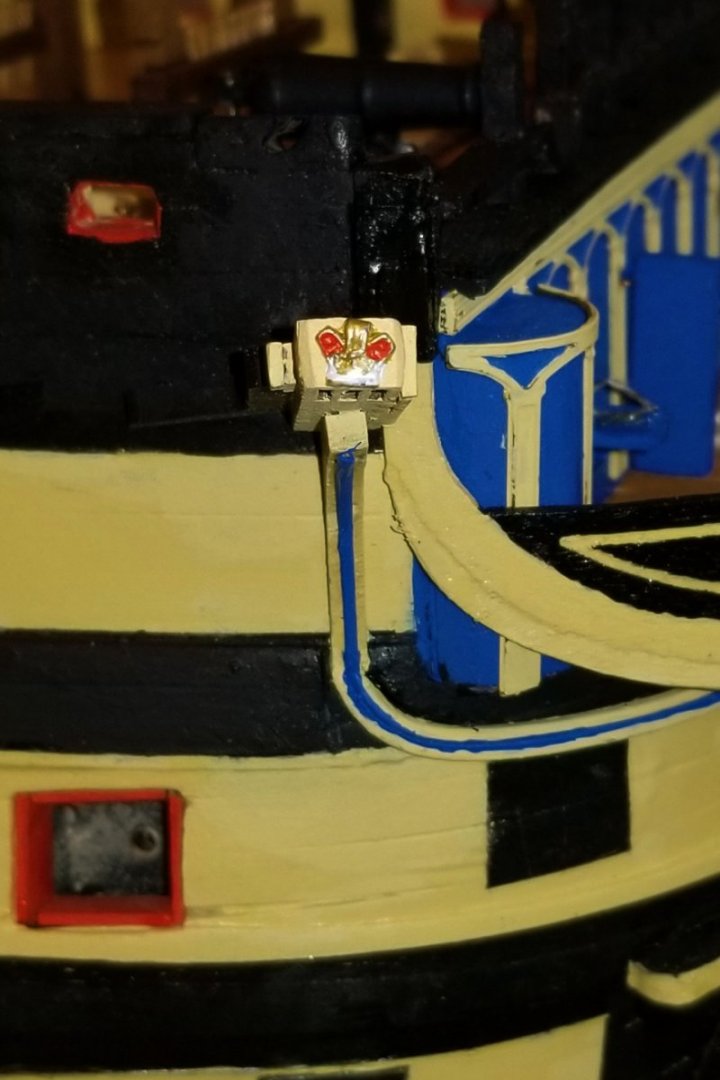
Finished painting and decorating the starboard quarter gallery.
Regards,
David
- mort stoll, Landlubber Mike, BobG and 4 others
-
7
-
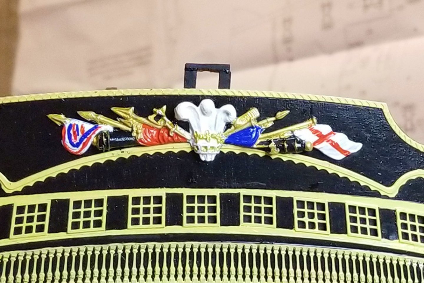
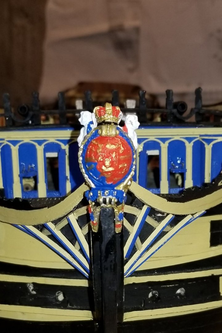
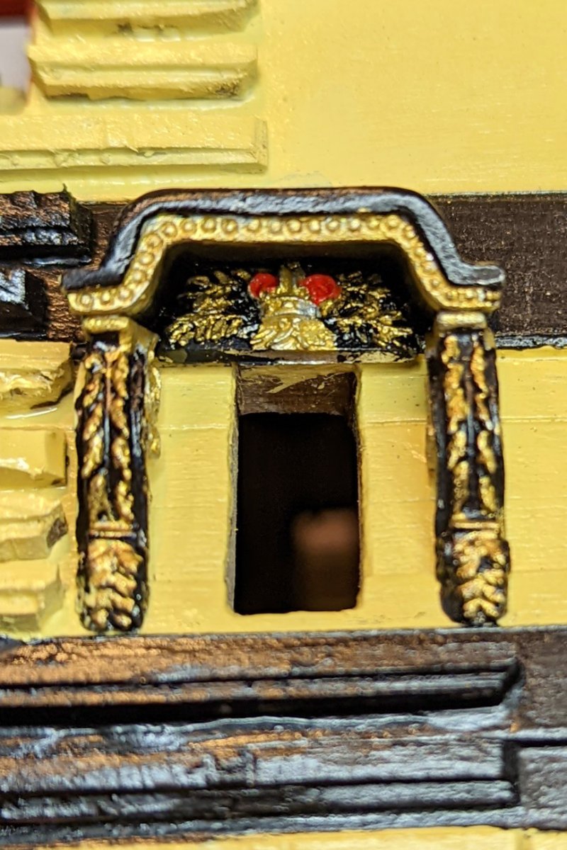
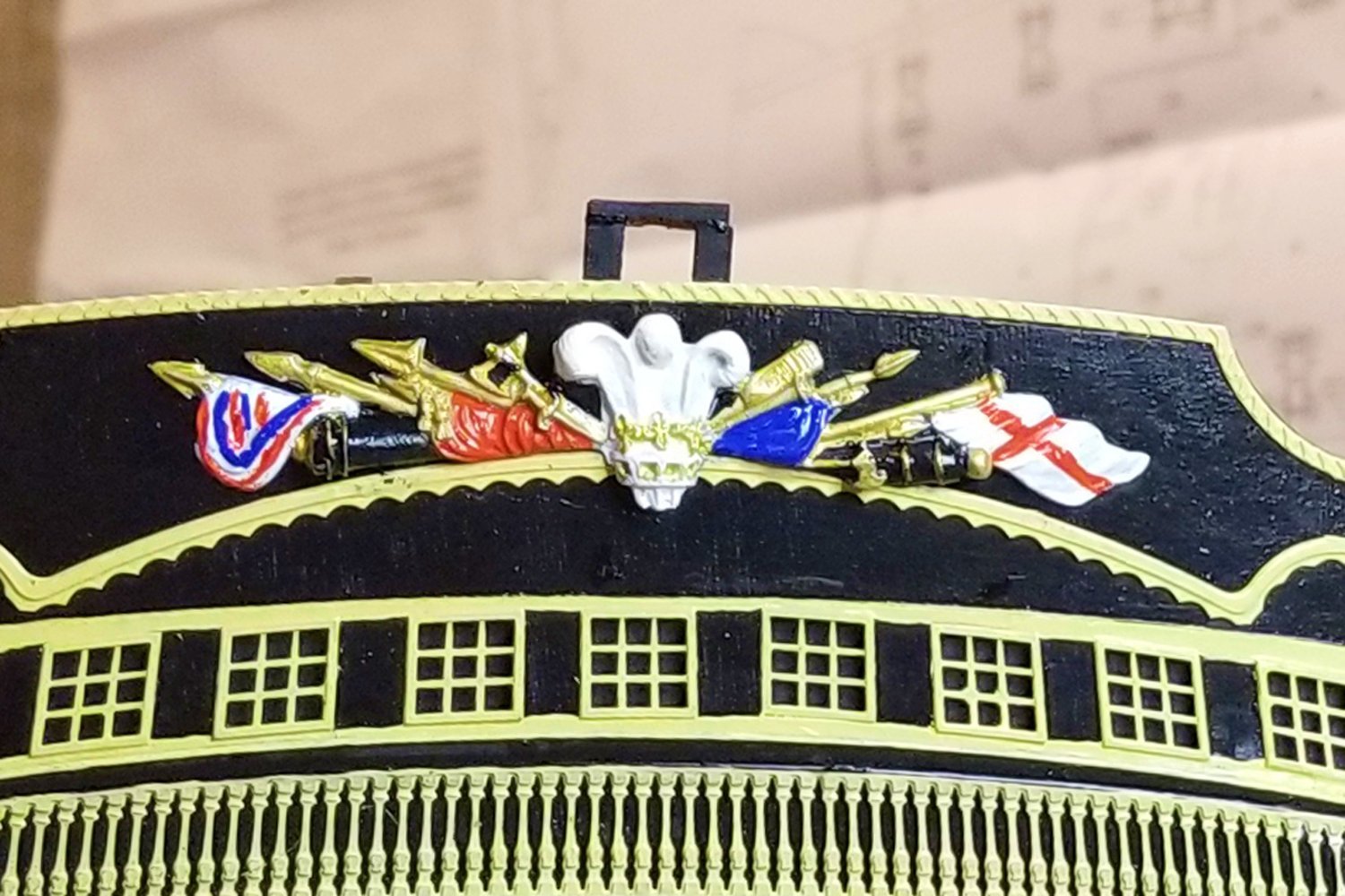
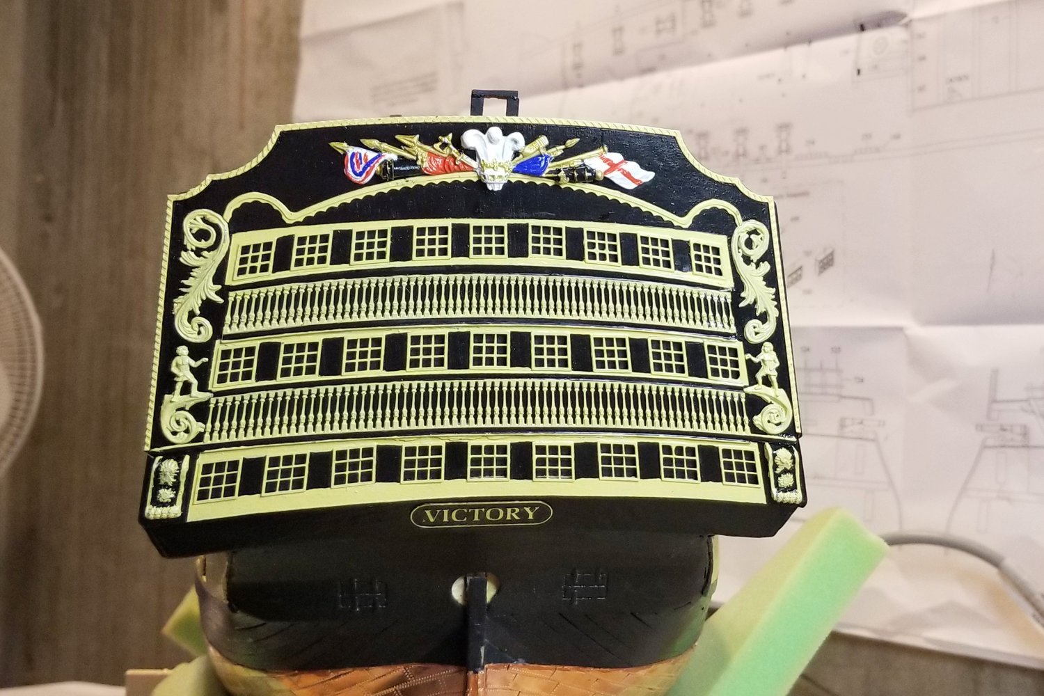
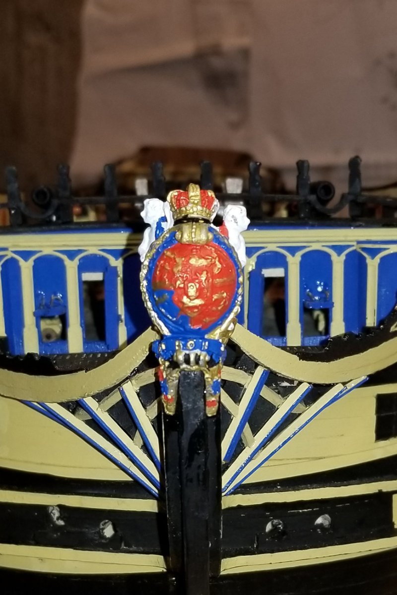
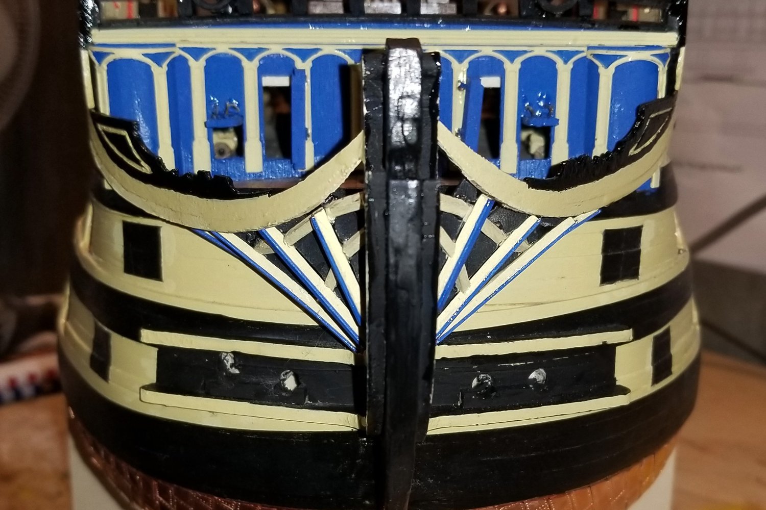
Finished the Trophy of Arms and the stern nameplate. Some notes:
- On the Trophy, the blue section to the right of the white crown is supposed to have some detail, but try as I might, I couldn't get those lines to show well, so I just painted it over as a solid color.
- On the nameplate, I didn't paint it yellow because I'd never have been able to get sharp lettering. So this is painted black and then the raised parts sanded off.
Regards,
David

-
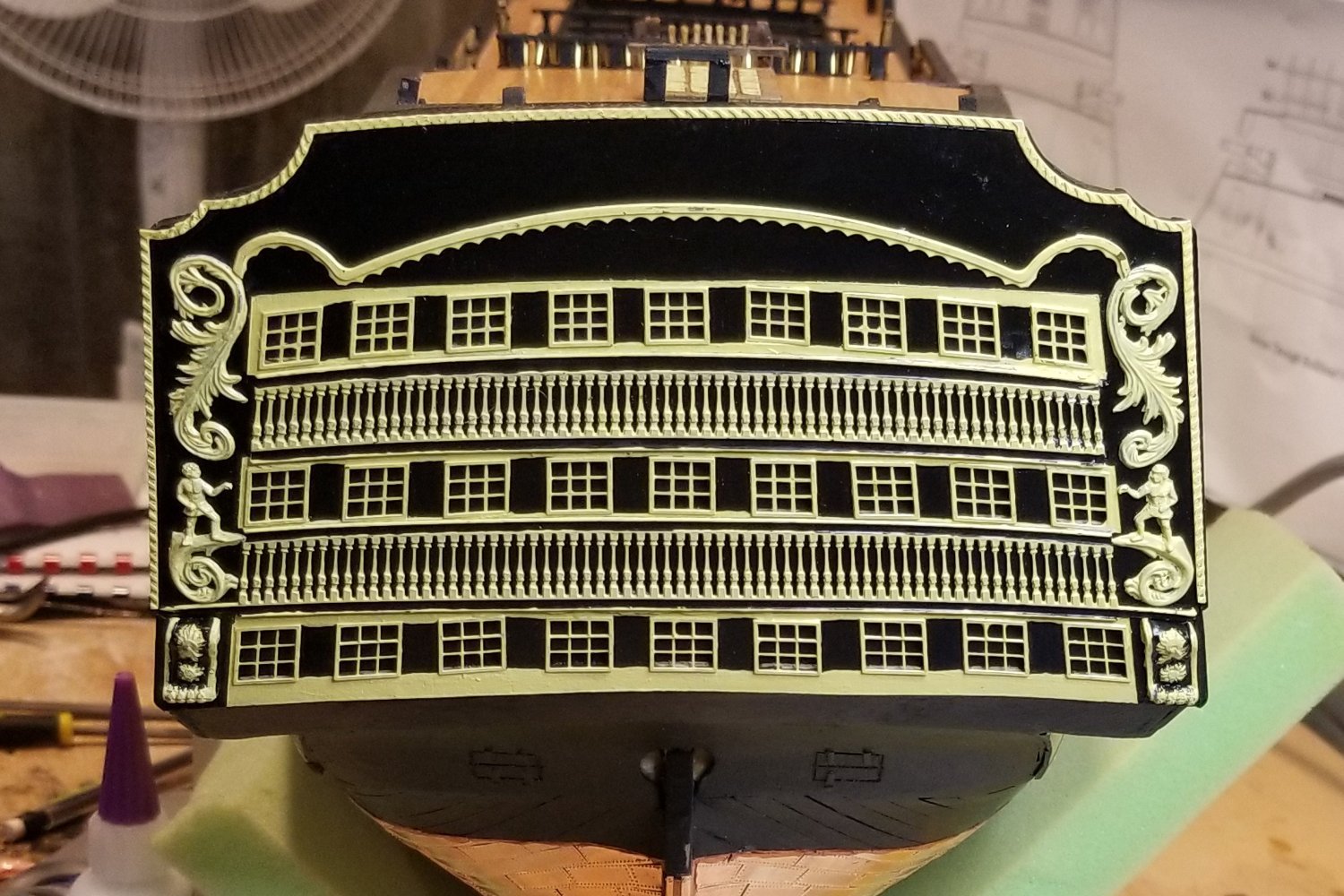
More progress on the stern fascia. What's missing from this pic is the trophy of arms (big deal micro painting coming up), and the nameplate.
I am not terrific at the fine painting, so we'll see what I get.
Regards,
David

- Kingspoke, mort stoll, Oldsalt1950 and 2 others
-
5
-
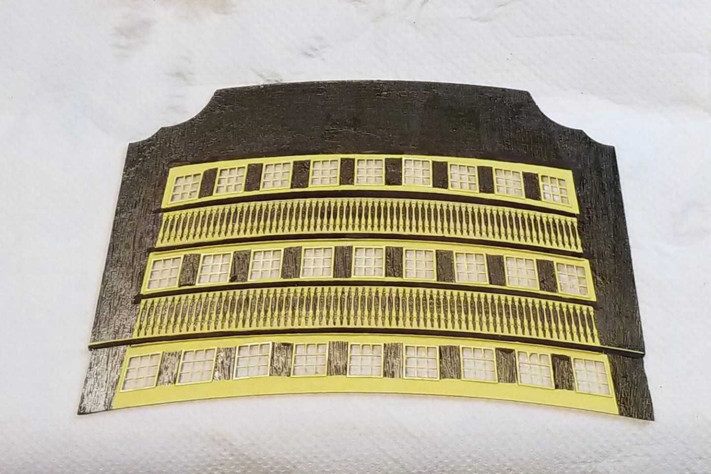
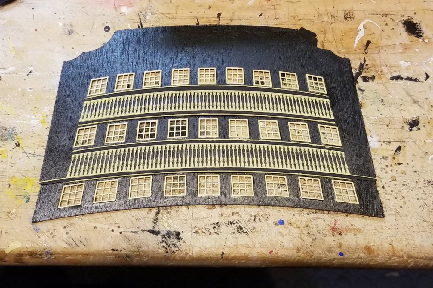
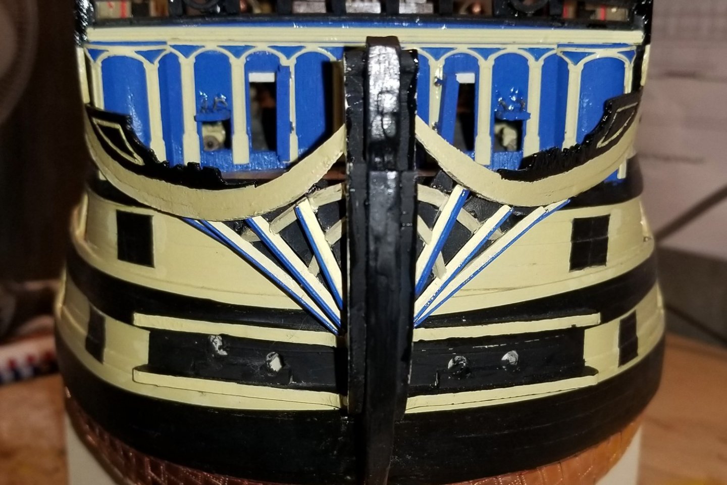
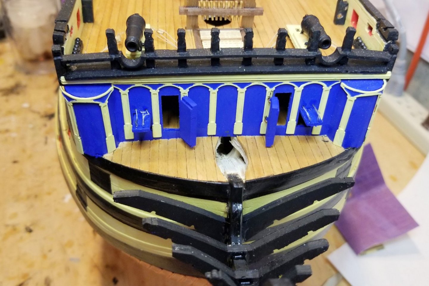
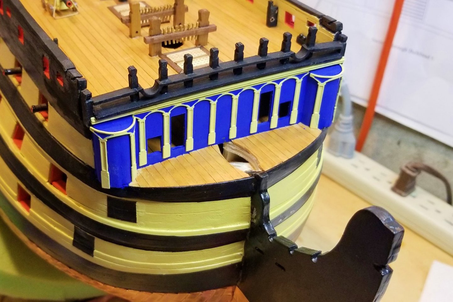
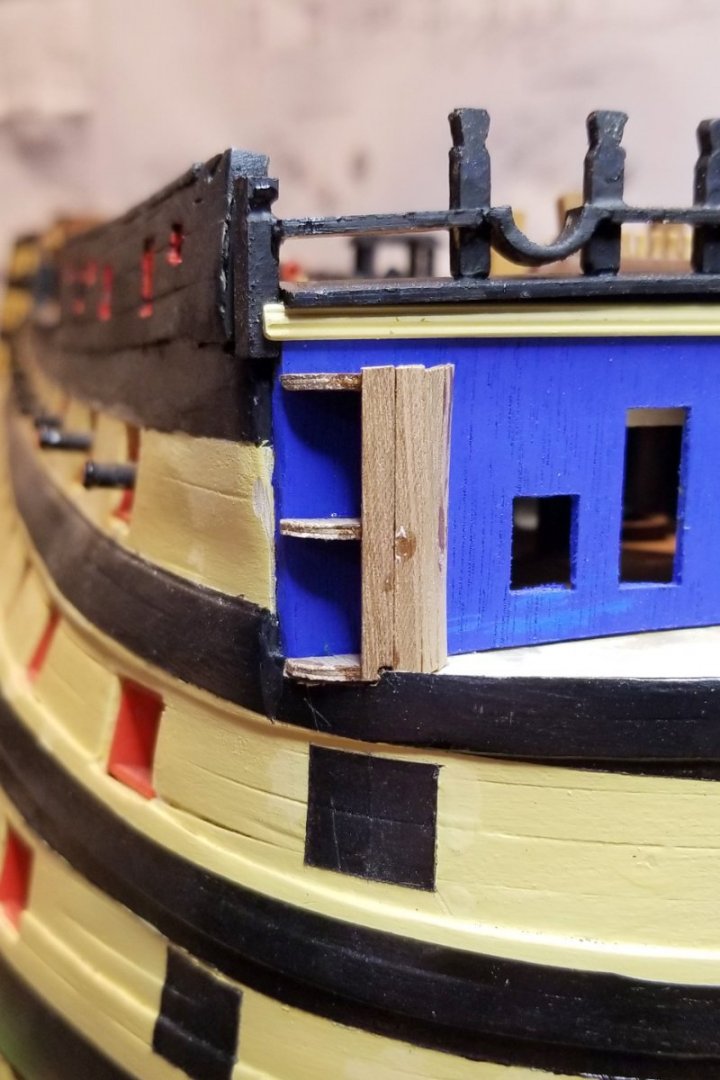
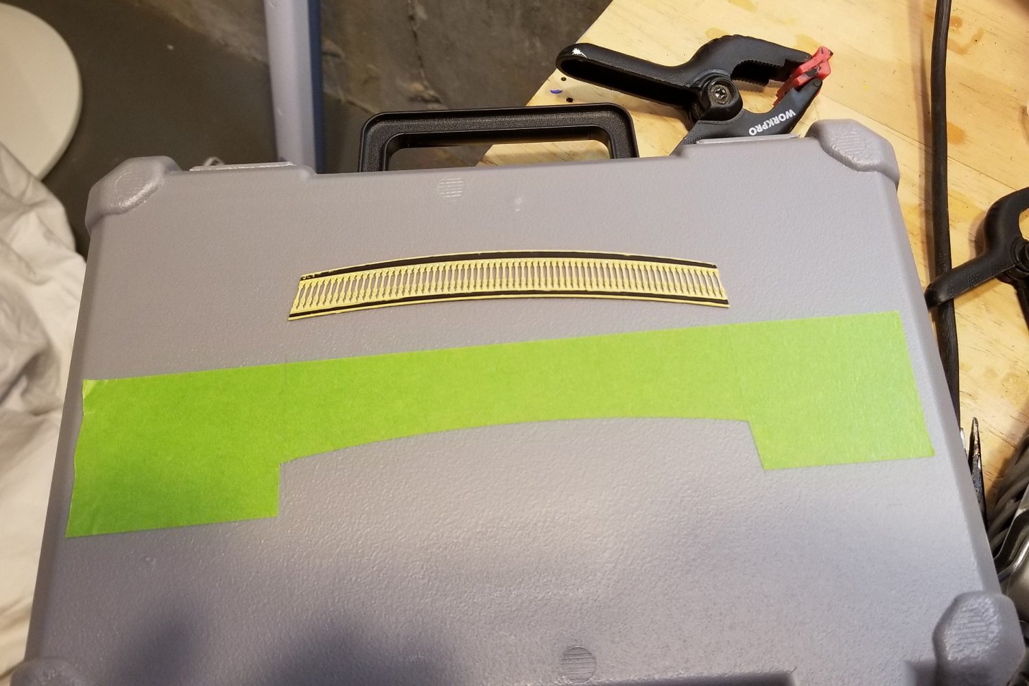
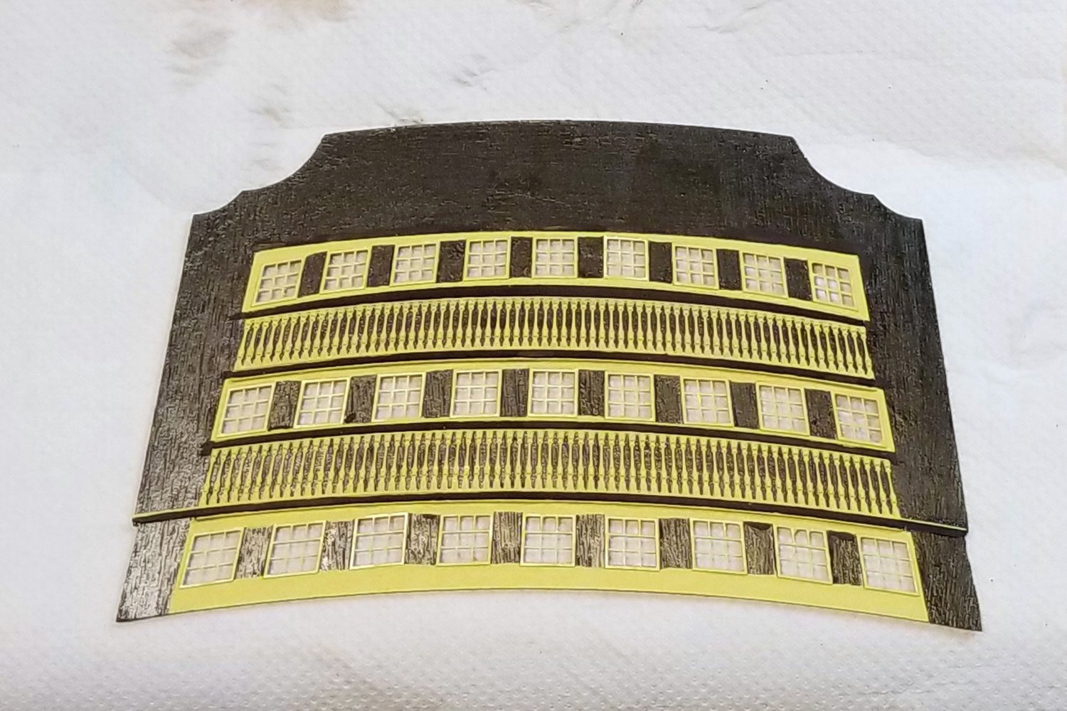
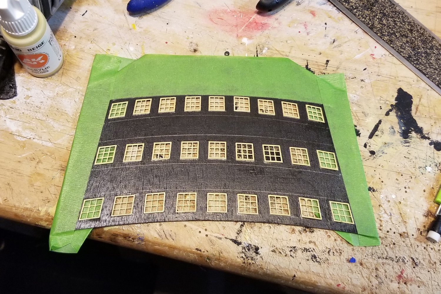
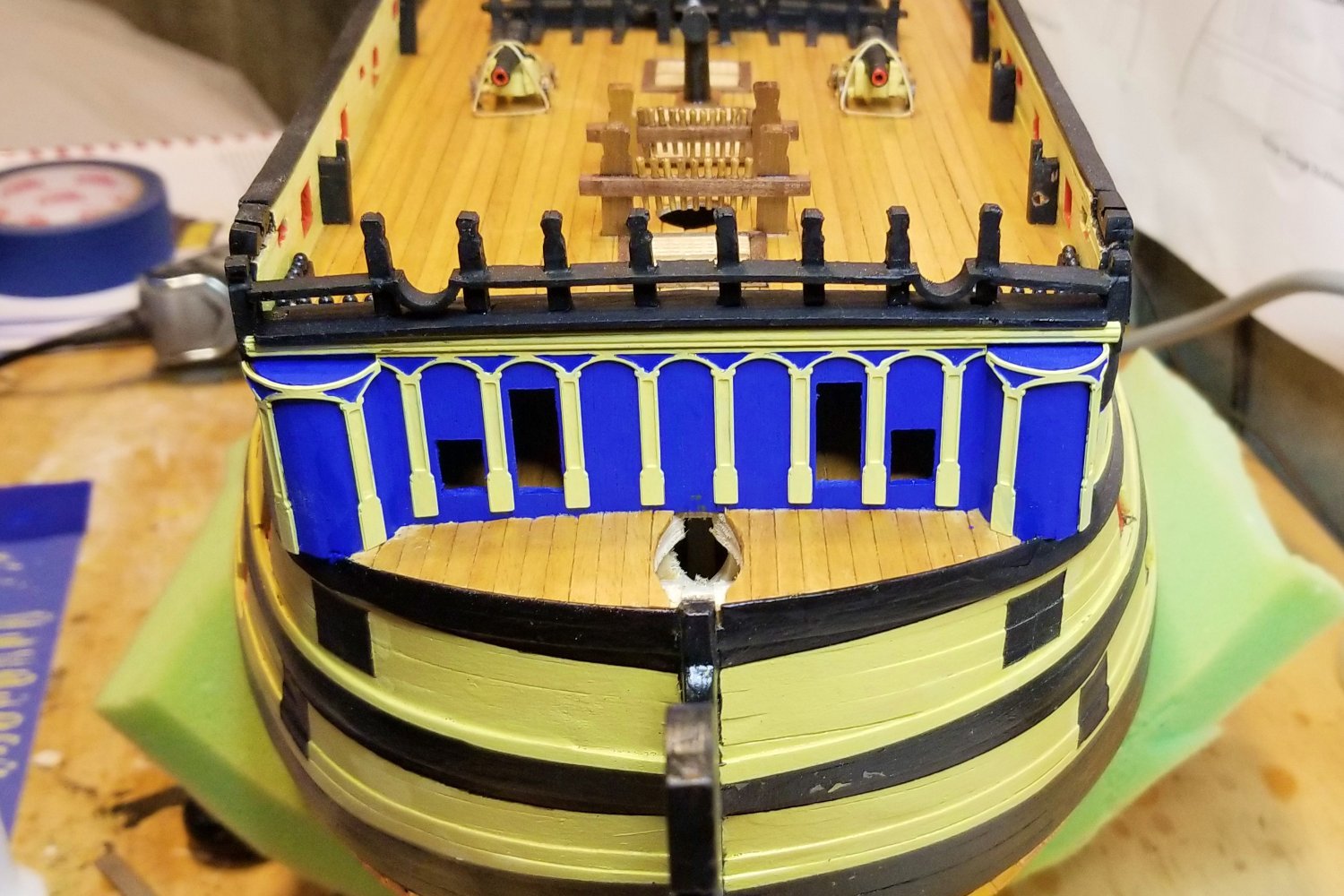
Working on the stern fascia. The dilemma was how to paint the yellow bands. Most get a good edge from the railing assemblies, but the top curve appeared to be a freehand job, which wouldn't look clean. Then it hit on me to cut painters tape to that curve using one of the railings as a guide for the knife.
Worked pretty well, with some touchup. The pictures show the process. [EDIT: The pics came up out of order. The third one below is pre-painting, dry fitted railings. Then the process with tape is #1 and #4, and then #2 is the finished product. I really wish the website wouldn't do this random reordering.]
Now I'm trying to see how much of this I can build off the ship before I mount the external fascia, because once mounted, detail work will become much more difficult.
Regards,
David


- Kingspoke, BobG, Knocklouder and 6 others
-
9
-
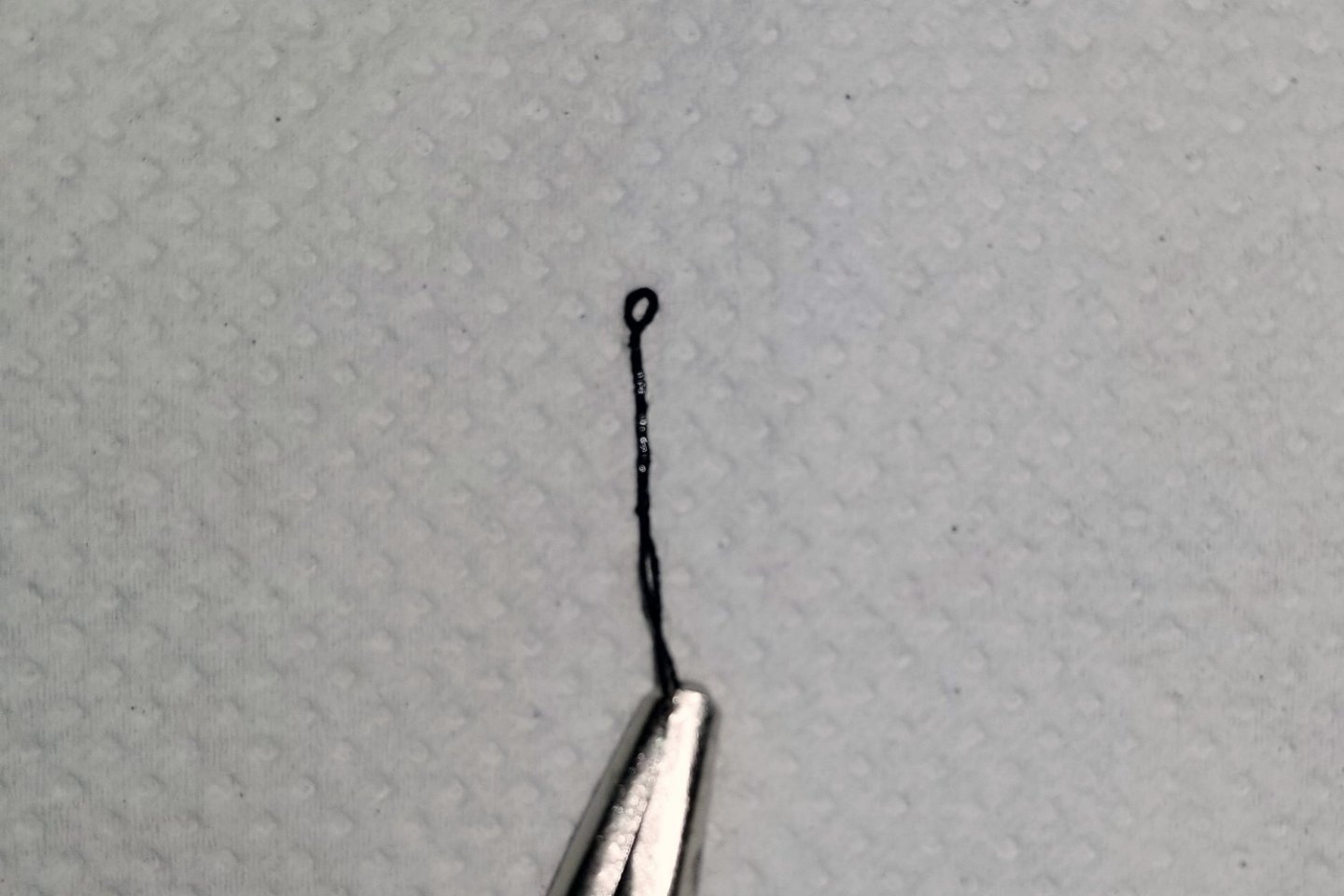
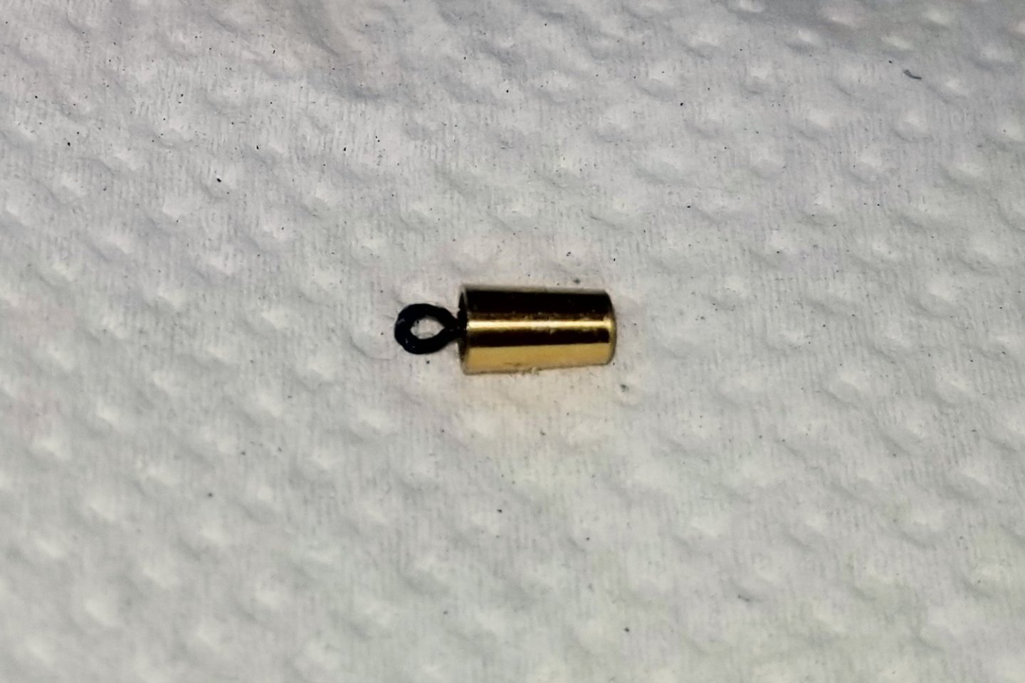
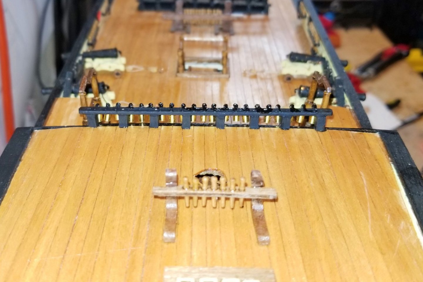
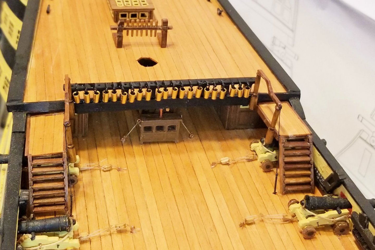
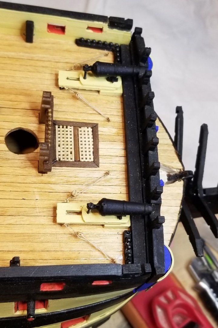
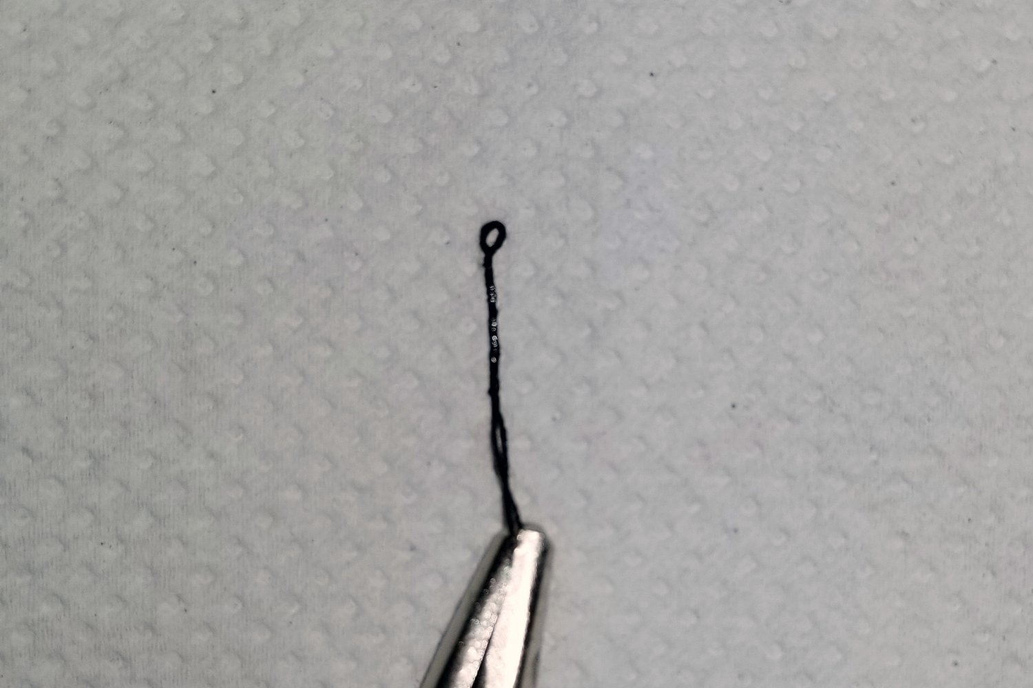
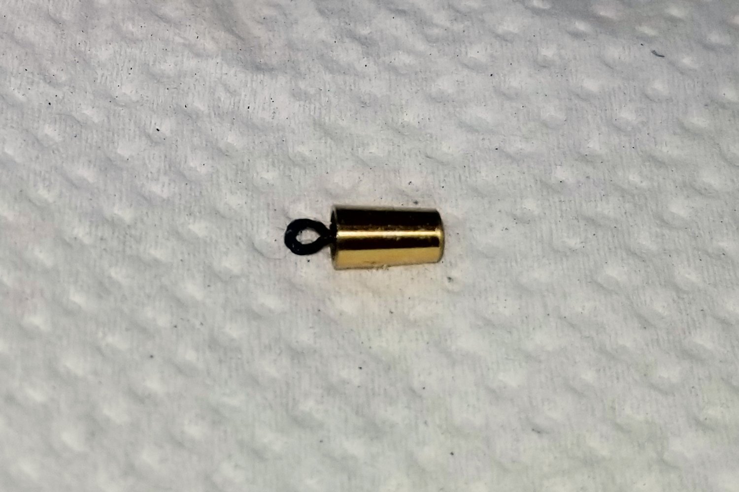
The buckets:
The manual says to drill the brass buckets to accept a handle, but I wasn't up for that, so I used a different approach pictured below. First, create a wire loop around a small nail. Then, glue the stem into the bucket.
The other pictures show the stern and bow side of the poop deck barricade, from which the buckets are hung. You'll notice that I did not paint them black as called for, because I like a bit of brass in every model and because I thought it would add more interest. It's almost impossible to get them perfectly aligned, but I think that wouldn't be as realistic as what came out here.
Regards,
David
-
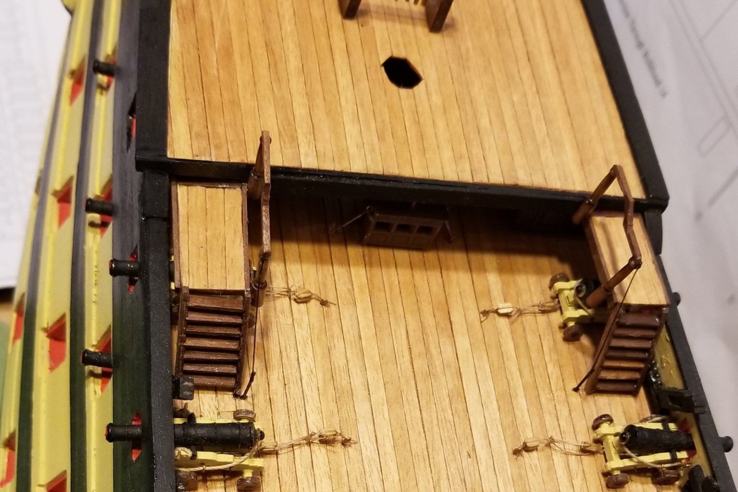
Built and installed the poop deck ladders.
Regards,
David
-
My previous post (and the one above it that I replied to) have the background for what follows.
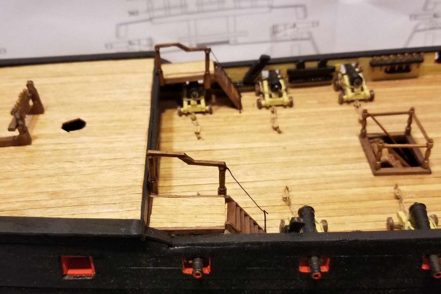
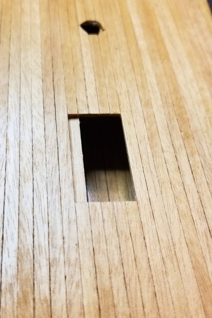
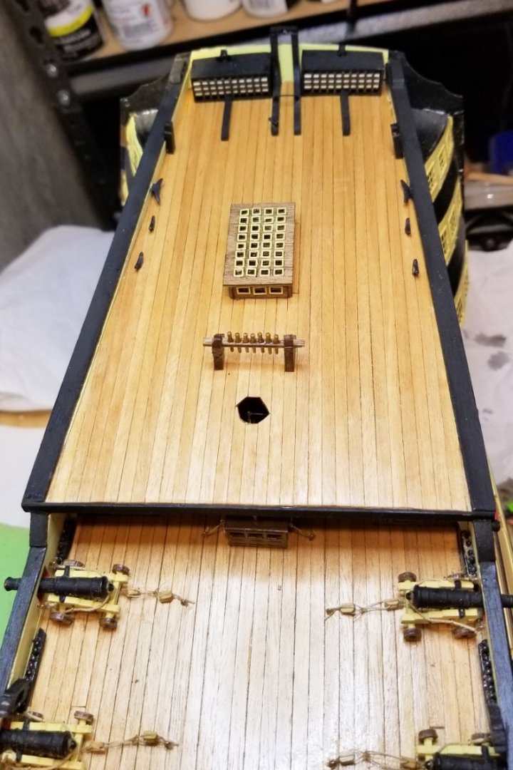
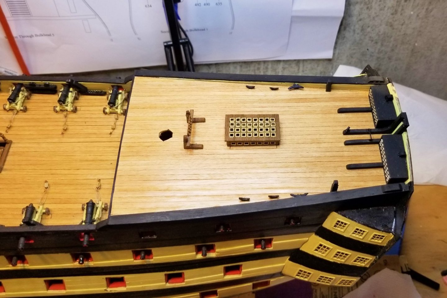
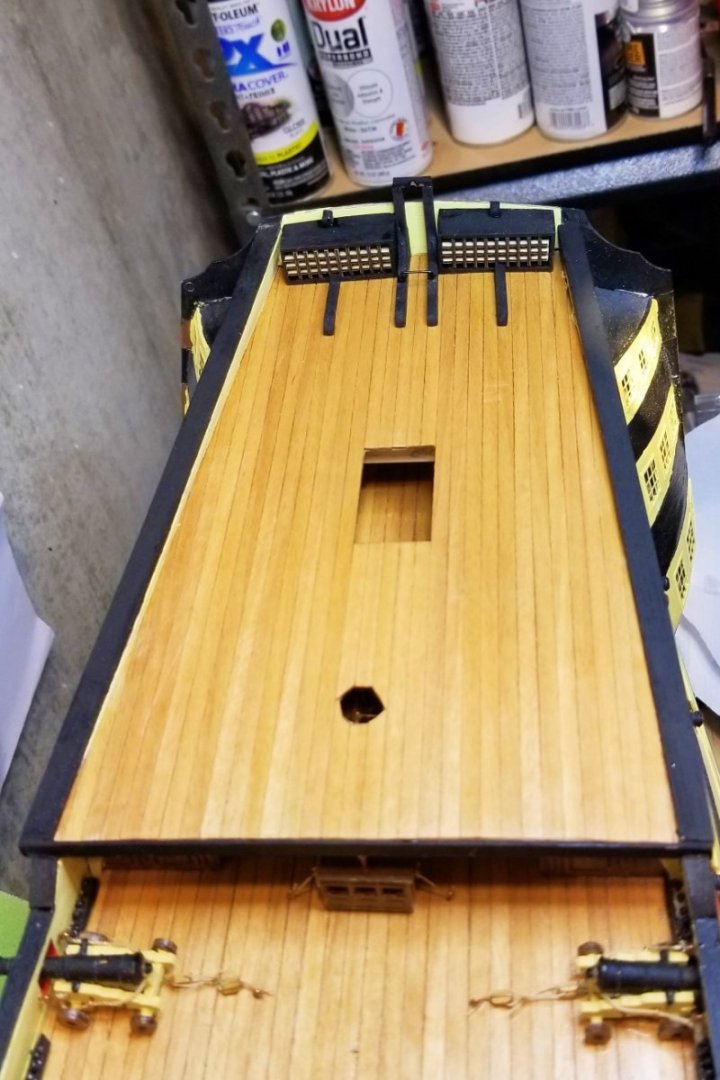
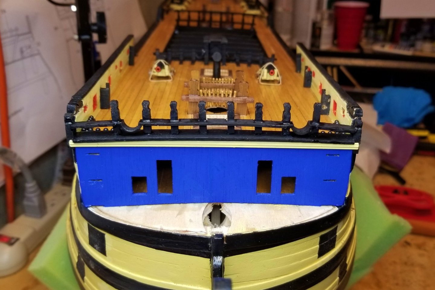
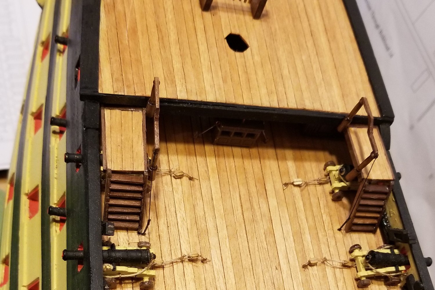
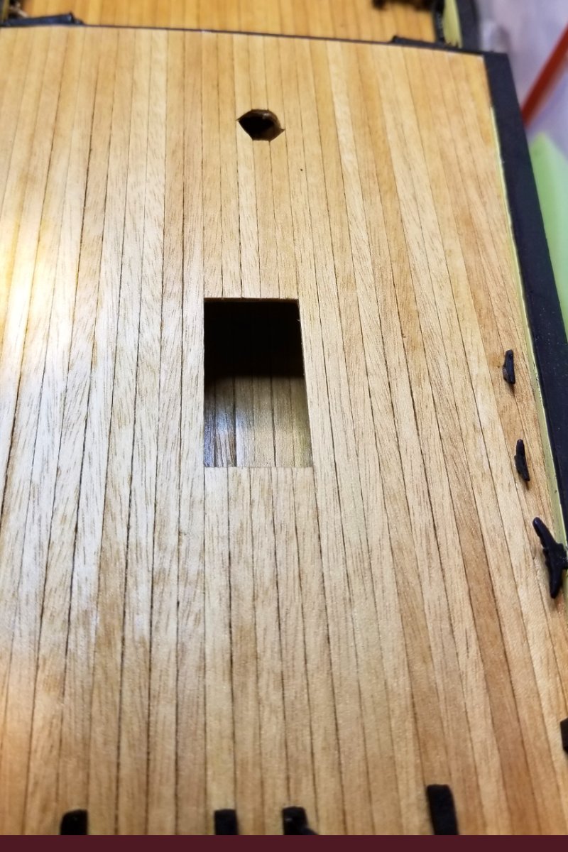
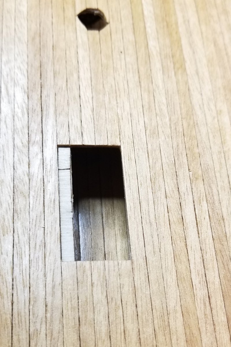
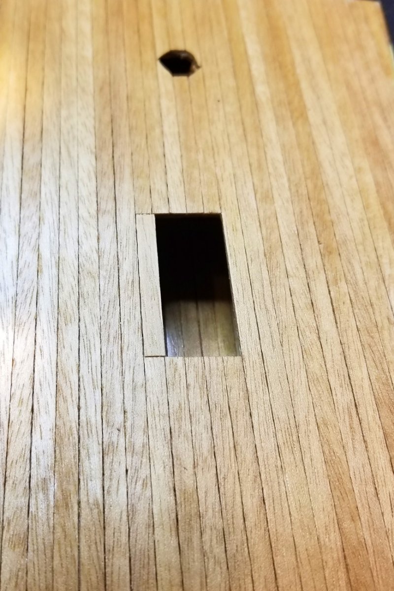
I decided to address the mizzen alignment issue (shown again below) by moving the skylight and bitts over. So I installed a length of plank under the deck, topped it with some scrap .8 ply to represent the height of the poop deck template, and then installed a fitted plank.
All of that allowed me to move over and center the skylight and the bitts on the mizzen hole. If you study it all from the end, you can see that it's all now misaligned with the flag lockers, but if you look at it from the side, it doesn't jump out at you, and I think will look fine once the shrouds and other rigging are up.
Regards,
David


-
Allan:
Not the camera angle -- your sharp eye has caught it. When I fitted the poop deck, I sanded it to fit, but then put a dowel down into the mizzen hole and then brought the poop deck down over it. Was misaligned, so I widened the hole in the poop deck ply so it would fit, and then when I planked it I did so to narrow the hole again around the dowel. But it is slightly off-center.
My guess is that things are misaligned down in the bowels of the hull, causing the mizzen to slightly tilt to starboard, and the effect of that by the time it gets to the poop deck is what you see.
I think it all goes back to the "dummy barrel strips" in the early hull building. In retrospect, I should have sanded them down to slide into the frames more easily. As it was, I had to knock them into place with a hammer, and that probably knocked some things out of alignment. The issue with those is that you don't really understand how tight the fit is until they are halfway in, at which point it would be really difficult to remove and sand them. Would be helpful if the manual had a tip on this. And in fact, I'm not sure it's the fit at all -- as I now remember I think it was just the curve, even though I soaked them in the bathtub before installing them. The space between the bulkhead frames isn't sufficient to manage the curve as you go in, so what I had to do was bend them down at the next frame, then knock in with a hammer. Even very softened wood would have an issue here.
The other effect of that is that when I ultimately go to install the dummy cannons, many of the holes their stems fit into are out of line -- some considerably. So I'm going to have to fashion anchors for them that I can fit in through the cannon ports and glue once inside.
Regards,
David
-
Mounted and planked the poop deck; built and mounted the flag lockers.
Regards,
David
- ccoyle, Bill Morrison, Gregory and 3 others
-
6
-
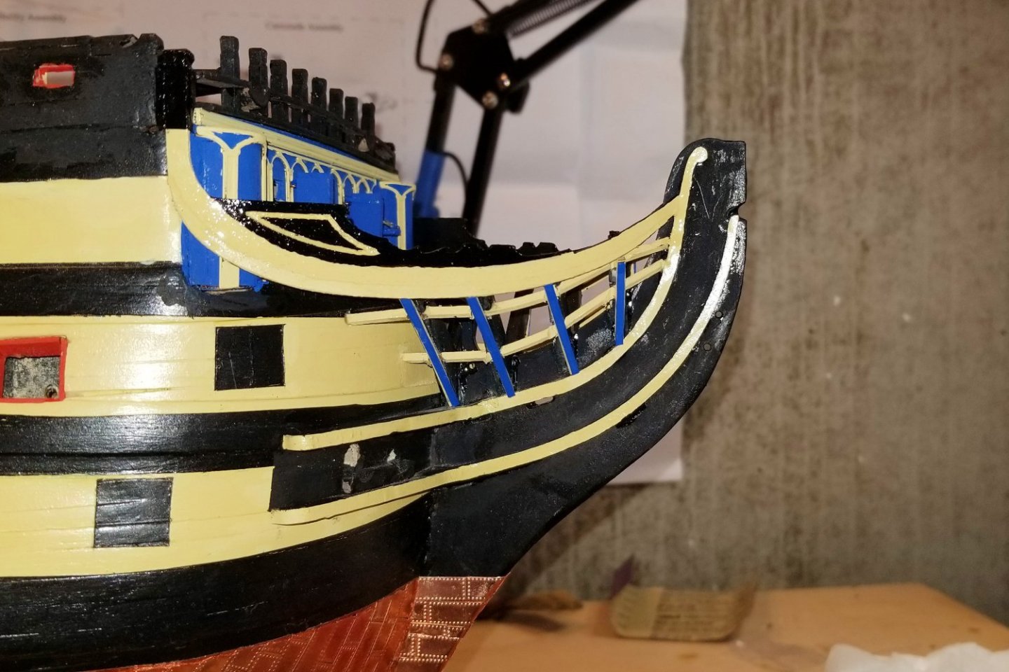
Finished up the bow by adding the mariners walk. The boomkins are built but missing from these pics, as I have them put away to avoid pranging them.
Regards,
David

- Oldsalt1950, Bill Morrison, Tom E and 5 others
-
8
-
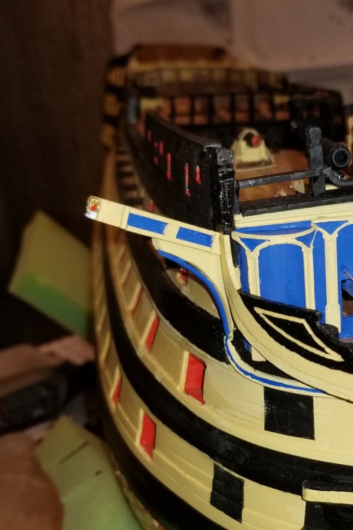
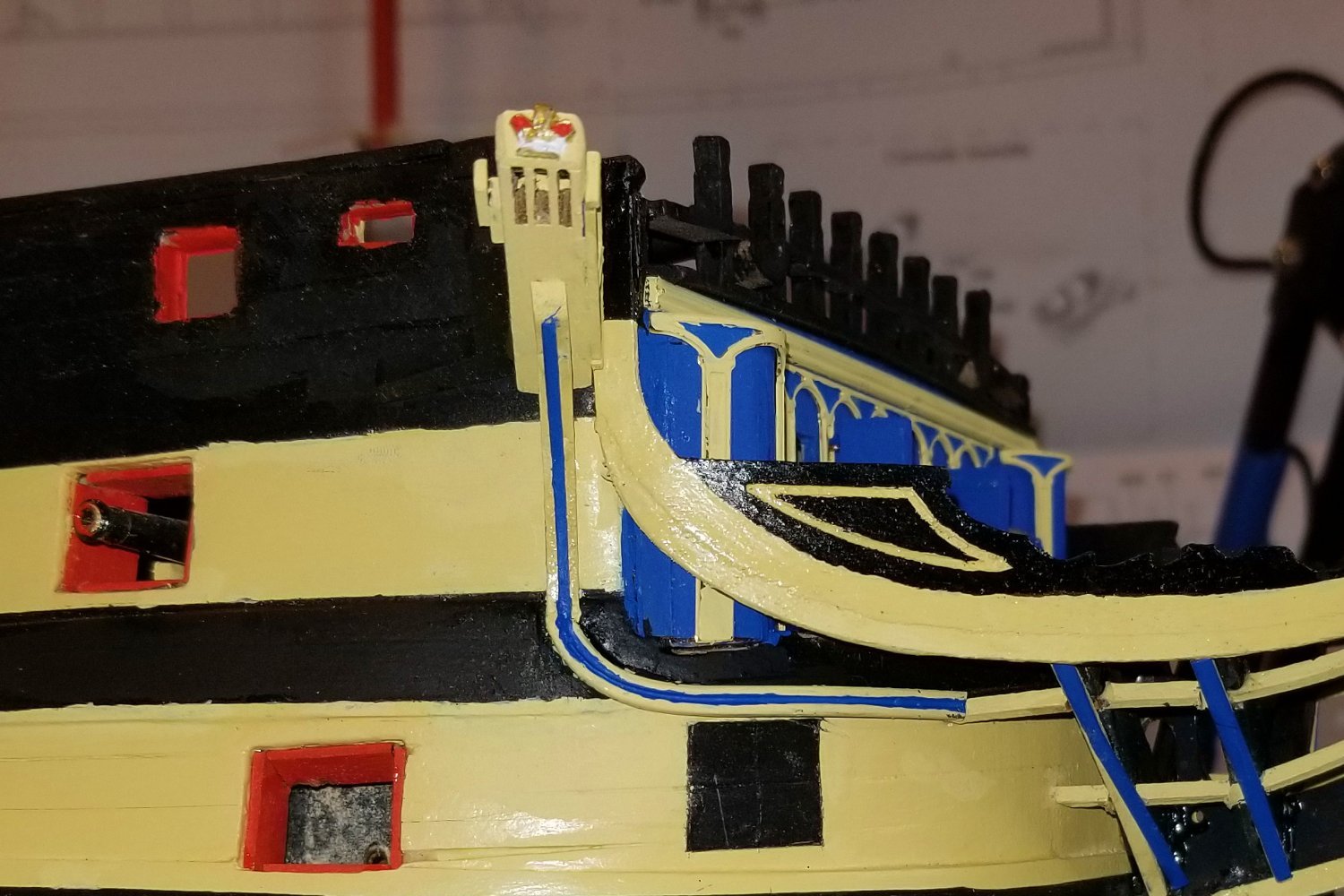
I've built the starboard cathead. A couple of construction notes:
- For the blue rectangles on the front of the cathead, instead of trying to use tape to get them straight (too small a surface), I painted a section blue (on top of yellow) and then added 1x1 yellow-painted strips to create the rectangles.
- For bending the brass strip to create the curve, I used a philips screwdriver pushed through a drilled hole in a 5mm board, heated the strip, and then bent a section into a 180 (so the two sides parallel). Then hammered the curve flat. I then cut that 180 degree curve into two 90 degree segments.
Lots and lots of touch ups required to get the blue stripe right.
So one side done, and now on to the other.
Regards,
David

- zappto, Bill Morrison, Tom E and 3 others
-
6
-
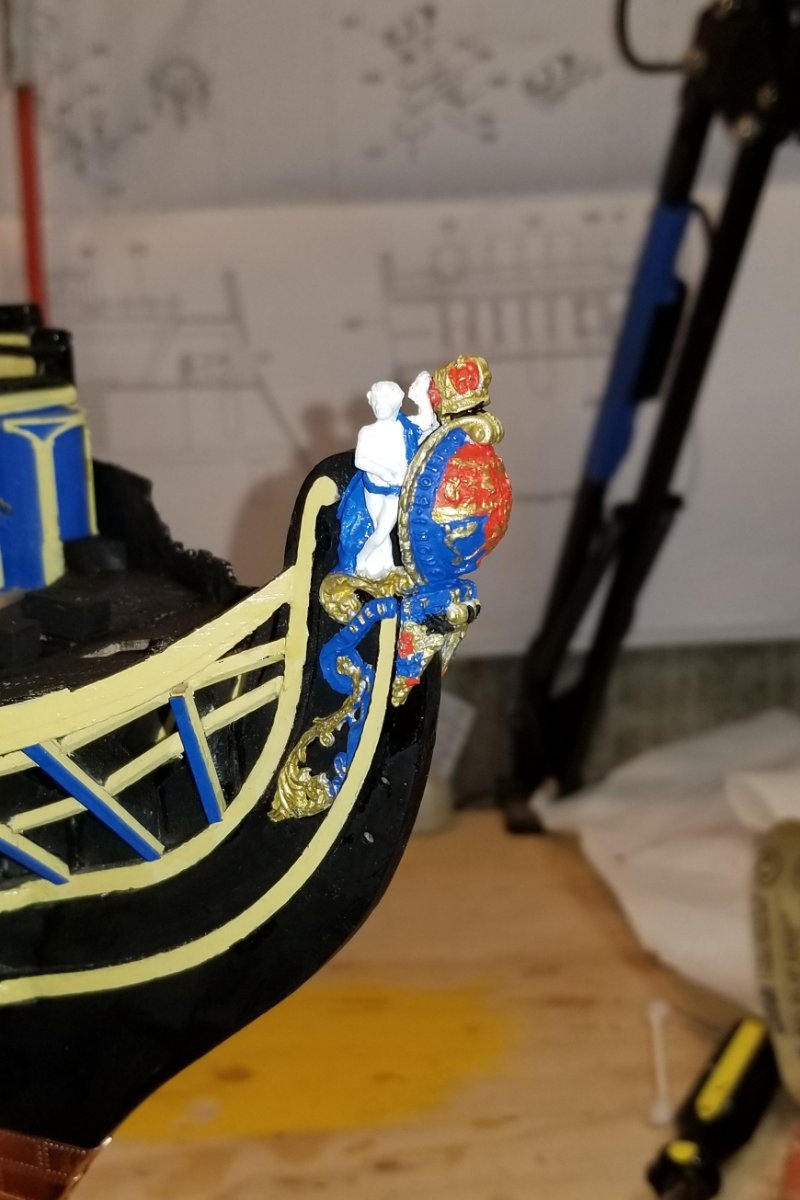
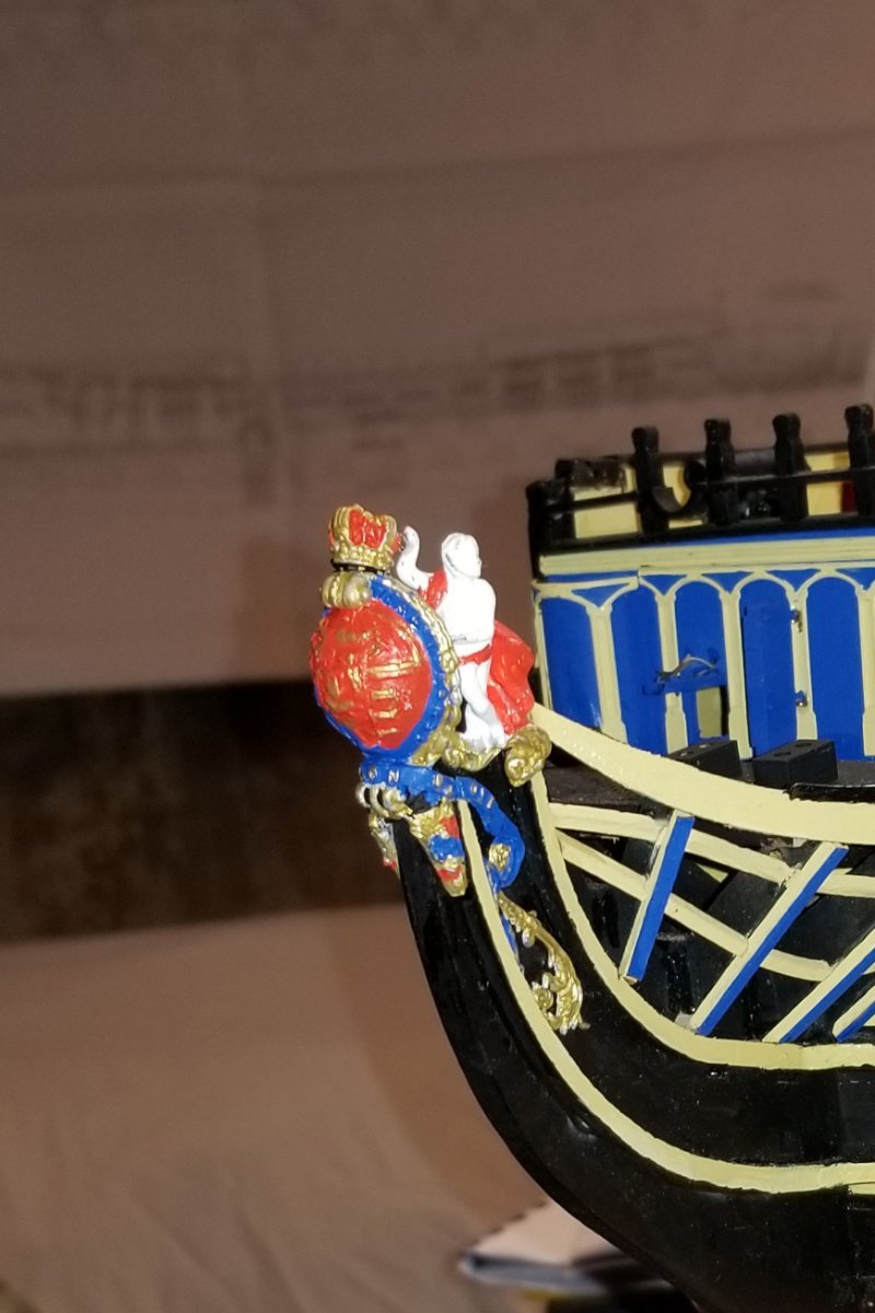
I got inspired today and painted and mounted the cast metal figurehead components.
Regards,
David


- mort stoll, BenD, BobG and 5 others
-
8
-
Installed the bow gratings and made the boomkins. The boomkins are dry-fitted using a pin in the knighthead, so that I can remove them for now (as the manual suggests) to keep from pranging them, and then reinstall them later.
Regards,
David
- Bill Morrison, mort stoll, allanyed and 3 others
-
6
-
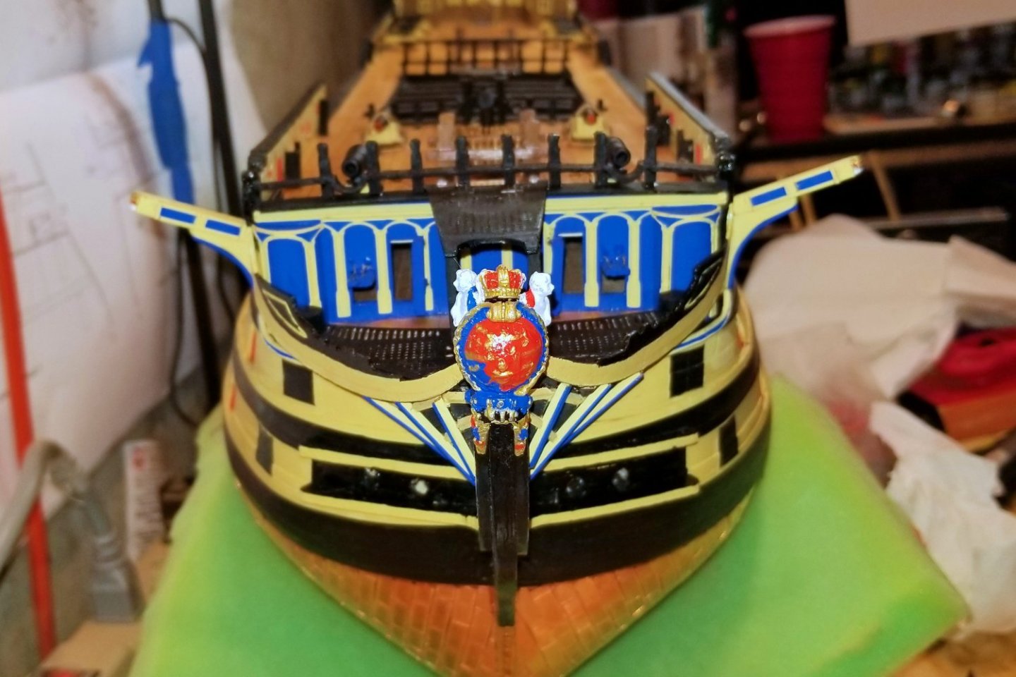
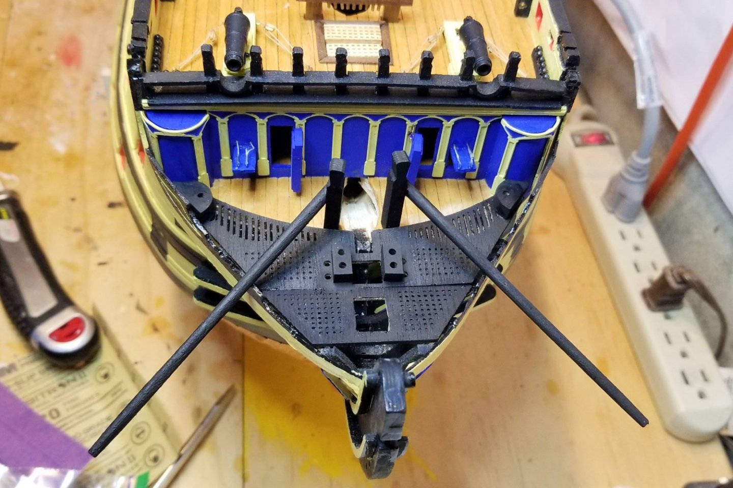
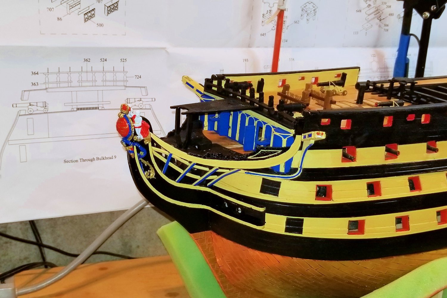
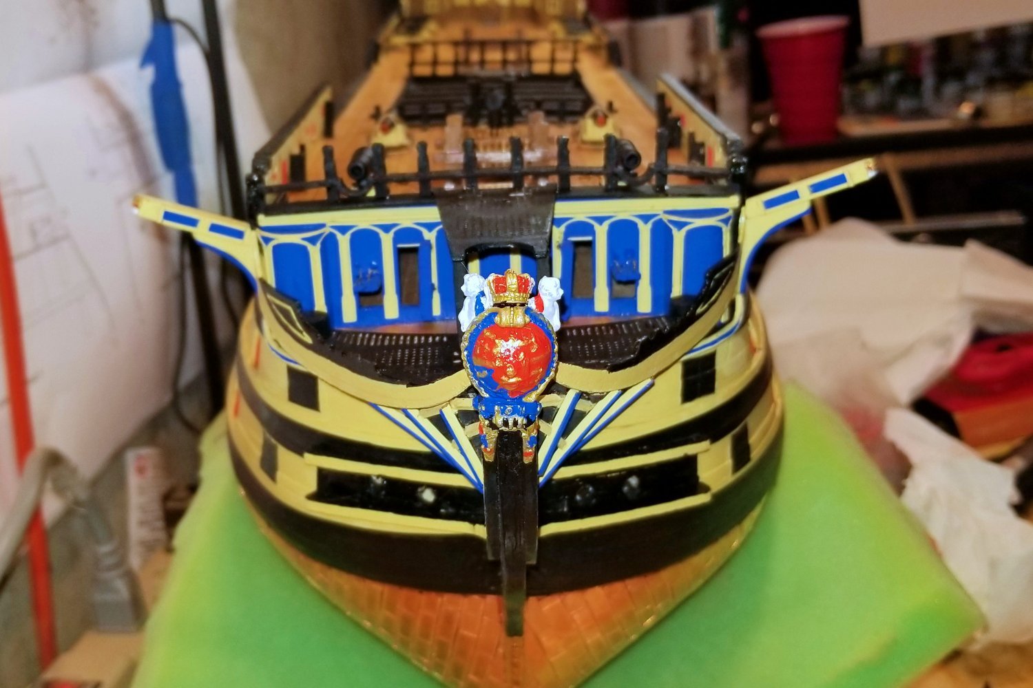
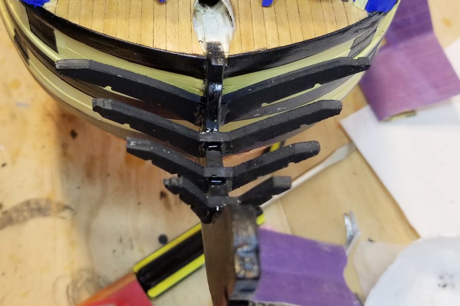
I've built the bow structure, which was something of an adventure.
The manual calls for the curved rails on the stem to be mounted before the head timbers are done, but the head timbers provide a guide for the run of the upper curved rail, so I mounted those first. Then mounted the curved rails.
The manual also calls for the remaining rails (horizontal and blue-trimmed vertical) to be mounted before the bow main rail, but again, it was much easier to install the two horizontal rails, then the bow main rail against the head timbers, and then cut the vertical blue-trimmed rails to fit under the bow main rail. By the way, the head-on picture gives the impression that the leftmost hawse hole is off kilter, but that's just an illusion of the inside of the drill hole.
Finally, the manual tries to be specific around the head timbers at the aft end of the bow main rails, but the instructions are confusing although I think I finally got it right.
For this section, I did a lot of advance dry fitting and thinking, referenced the invaluable pics on the Caldercraft website, and got the idea to pre-mount the head timbers from another build log on MSW.
Next step is the bow gratings that fit inside this structure.
Building this part reminded me of the difference between this model and some of the Amati ones I've built. For some reason, things just seem more complicated on this model. I think it may be the amount of cutting, fitting, and pre-painting of small parts that tend to stay in walnut on the Amati models. In any event, I'm happy building this, although my limited skills are sorely tested.
Regards,
David

- etubino, GrandpaPhil, mort stoll and 2 others
-
5
-
Completed the cannonades, and mounted the doors and gunport lids on the bow area.
Regards,
David
-
Finished and painted the roundhouses, planked the beakhead deck, and added the painted brass decoration.
Regards,
David

- Bill Morrison, etubino, Ryland Craze and 4 others
-
6
-
 1
1
-
Bill:
Thanks for the nice comments. I'm glad the log is somewhat useful.
Regards,
David
-
Re my message above, here's a picture of one of the roundhouses in process. I've finished planking the other one, and there's a pretty curved shape before sanding, so sanding shouldn't be too hard. I'll glue some sandpaper to a stick and have at it.
Regards,
David
-
Graham:
I have already given up on the idea of removing the roundhouses. Because the partial trim leaves some of the wale in place, there isn't really any way to just slide the roundhouse structure out -- you'd have to tilt it and the tabs wouldn't work properly.
So I glued the patterns on to the bulkhead and have started planking, and will do the sanding carefully with a stick and some sandpaper.
Regards,
David
- mort stoll, Oldsalt1950, Charter33 and 1 other
-
4
-
Built the railing across the bow. Next step is the roundhouses. I'm a bit wary of trying to sand them on the ship -- thinking about planking them while dry-fitted, and then removing for sanding. We'll see if I can pull that off. Might be blocked by the wale position at the bottom.
Regards,
David
- GrandpaPhil, BobG, chris watton and 3 others
-
6
-
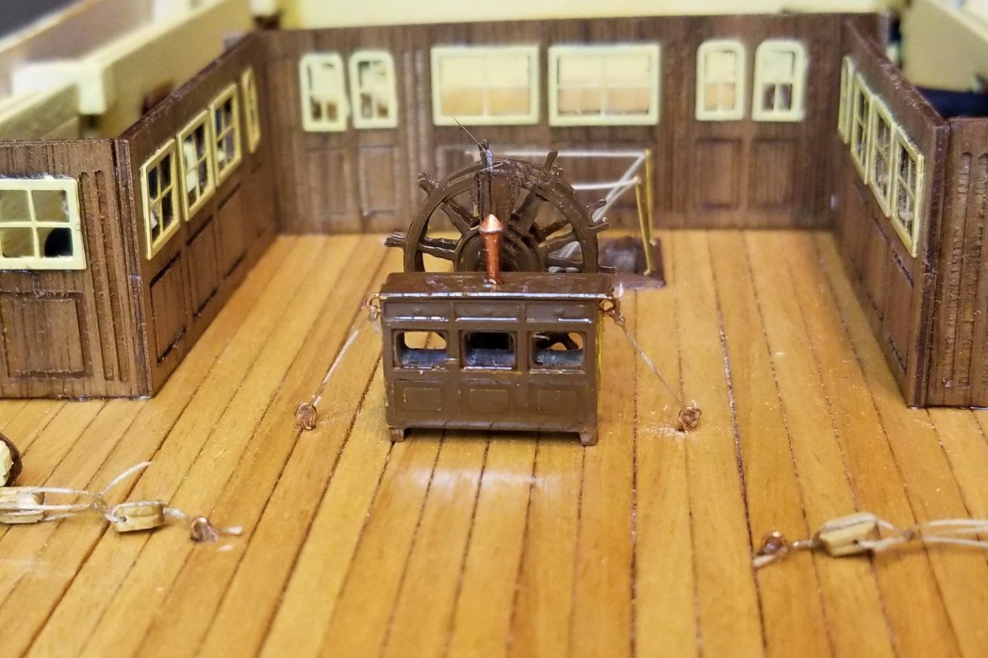
Ship's wheel and binnacle finished and mounted. The scratches on the wheel are light reflection and don't show to the naked eye.
Regards,
David


HMS Victory by drobinson02199 - FINISHED - Caldercraft - Scale 1:72
in - Kit build logs for subjects built from 1751 - 1800
Posted
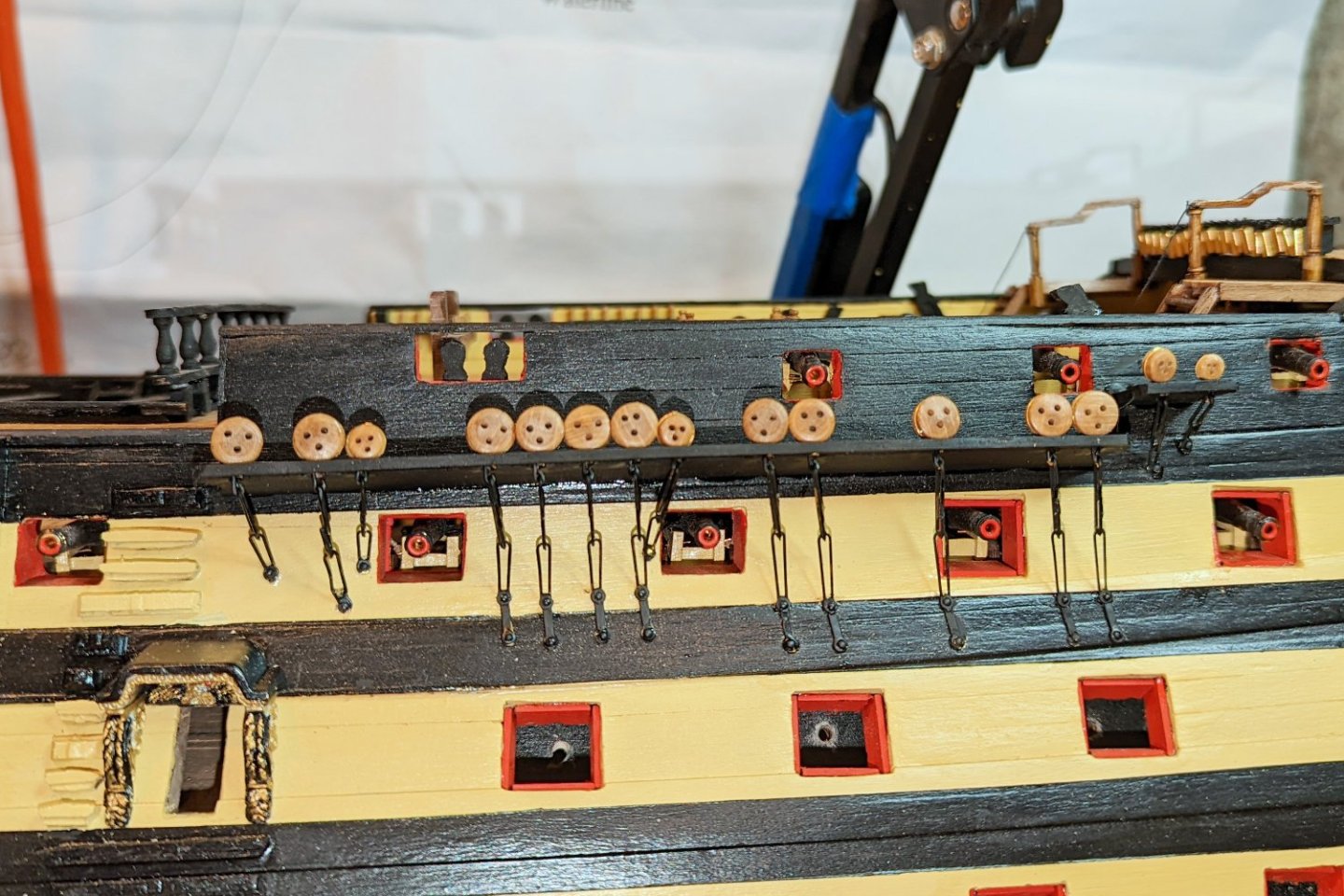
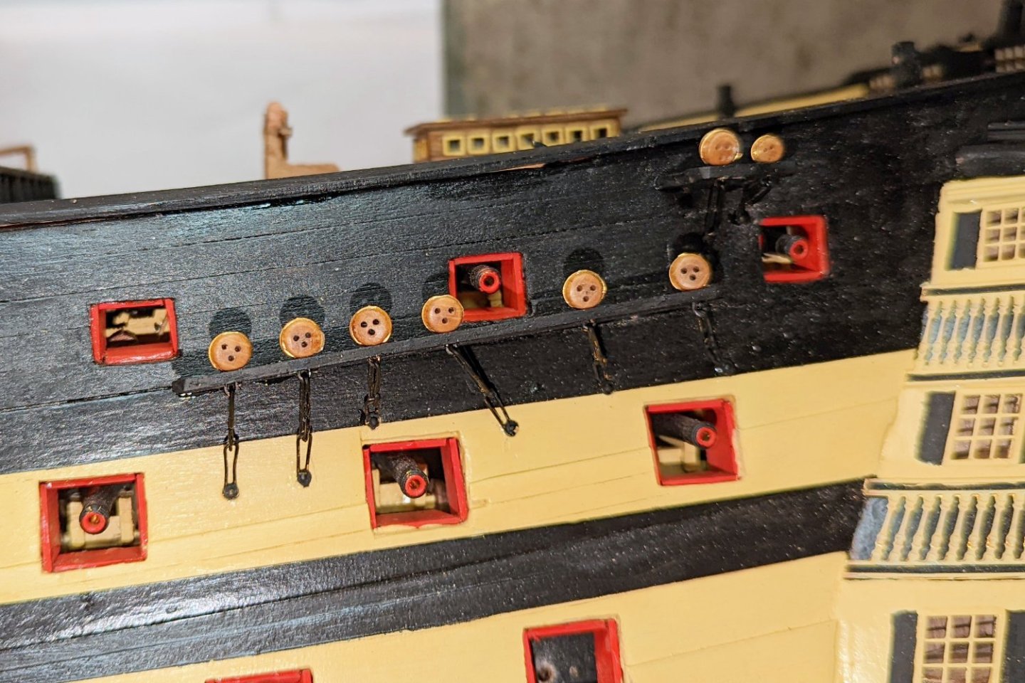
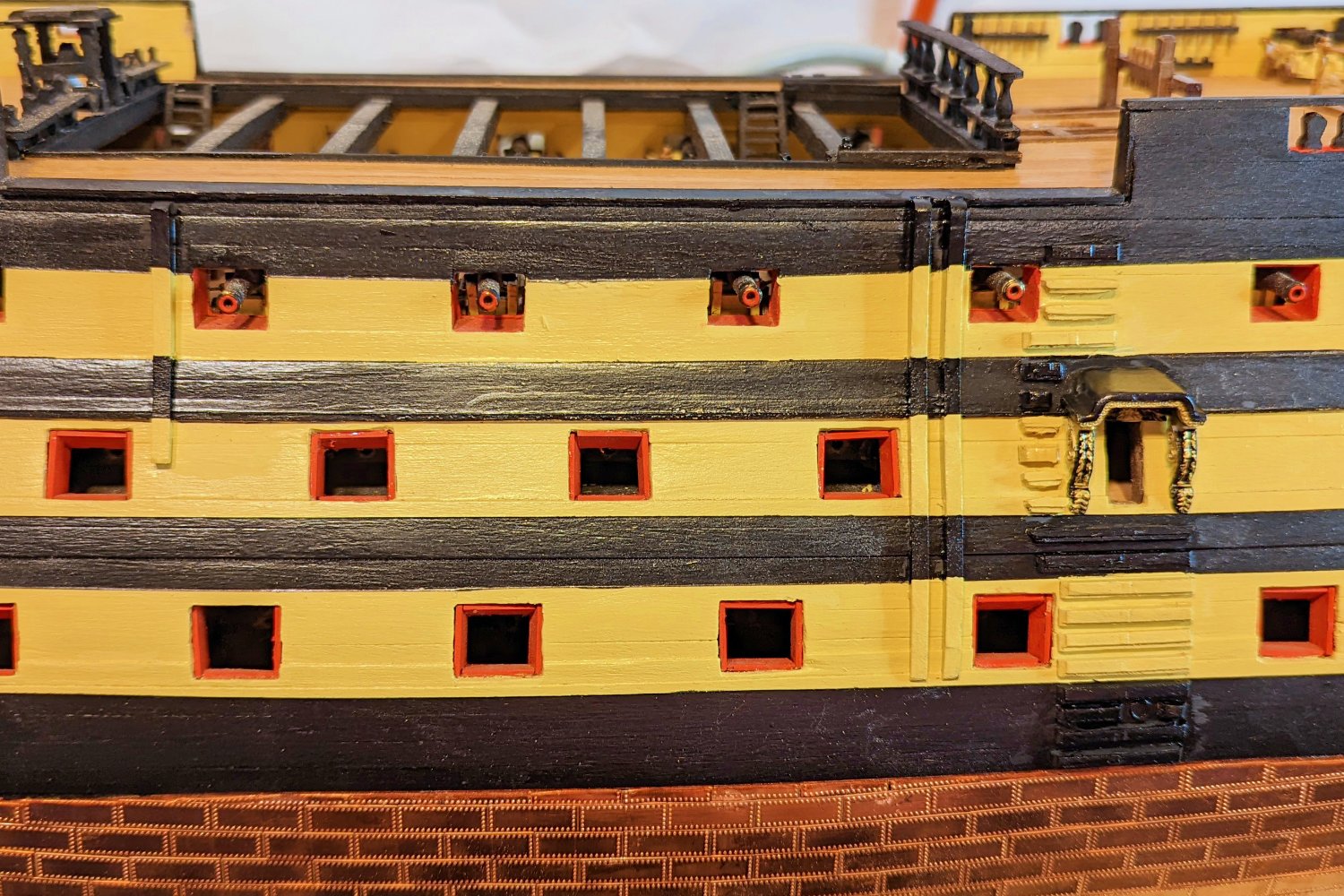
Completed the dummy cannon barrels, the gunport lids, and the "rigols". From the date of my last post, it looks like this took about 8 days for both sides.
Full disclosure:
Regards,
David