MORE HANDBOOKS ARE ON THEIR WAY! We will let you know when they get here.
×

Captain Slog
-
Posts
904 -
Joined
Content Type
Profiles
Forums
Gallery
Events
Everything posted by Captain Slog
-
 Hi Mindi, glad to see you back on your Endeavour. The photo-etch sheet is available from Cornwall Model Boats if you have no luck from Jotika. http://www.cornwallmodelboats.co.uk/acatalog/caldercraft-brass-etch.html Cheers Slog
 -
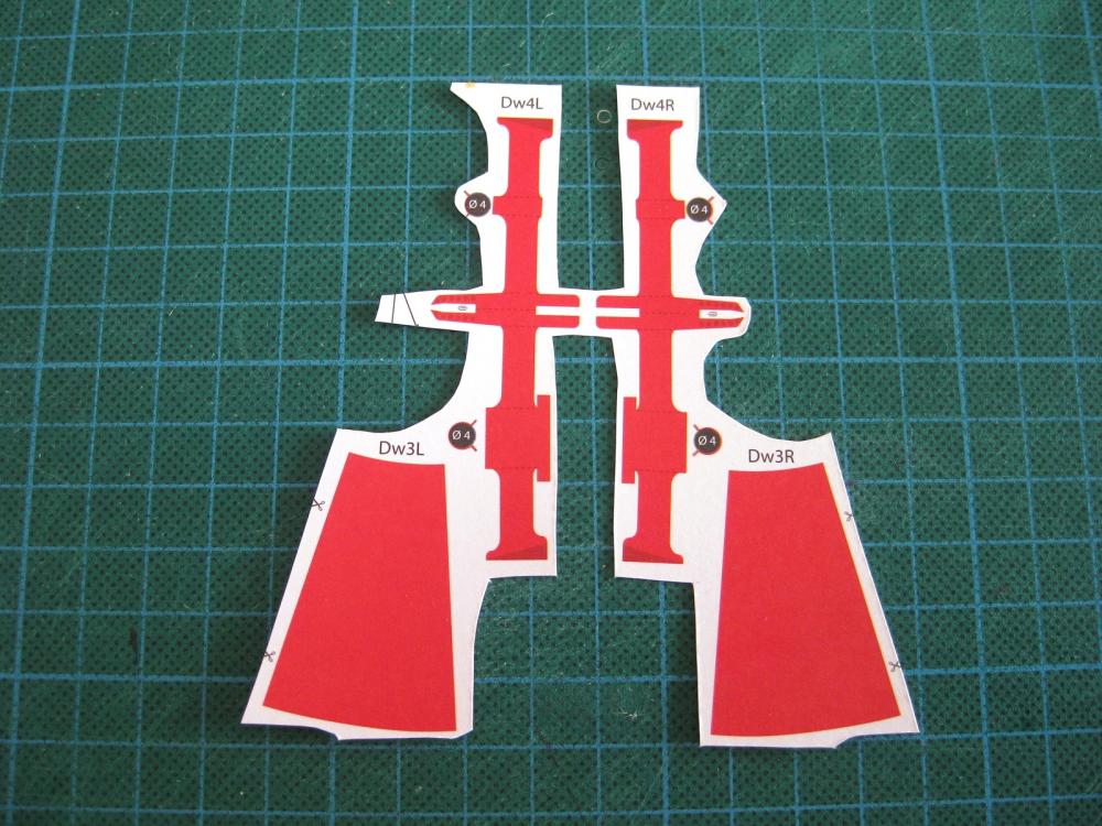
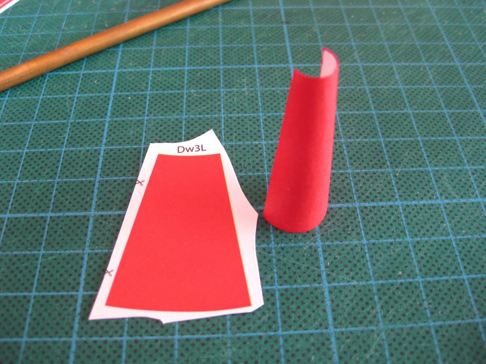
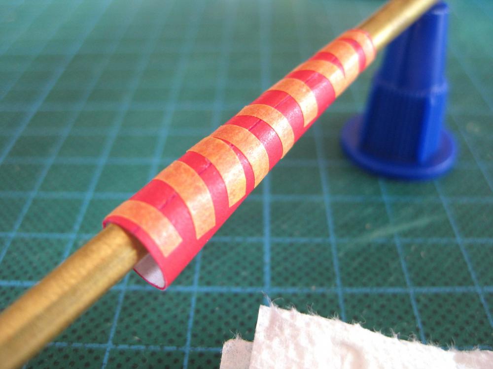
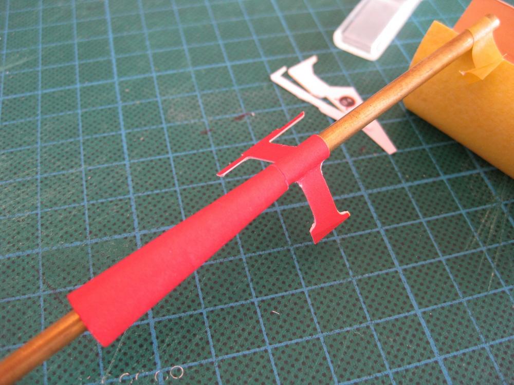
Hi All, I have managed to squeeze in a bit more modelling. I am slowly working on the lower hull which I have skinned and suffice it to say my hull skinning still isn’t up there yet so I am currently filling and sanding when time allows. I won’t go into detail here as I will make a post when it’s done but will say I half expected that I would end up painting it and am comfortable with that and it hasn’t dented my enthusiasm. So continuing with the lower hull attachments the prop shaft shrouds and supports were up next as these are close to being fitted. Here are the 2 shrouds and 2 supports ready for cutting out. These are left and right handed. I also write L and R on the backsides of parts so I don’t get them mixed up. Sometimes its not as obvious as these. Use a pencil for this and not a pen for obvious reasons. One shroud cut out and partially formed. These are truncated cones with the small end to go over the prop shaft and the larger end to align up with the hull shaft bulges. The same principle for forming applies as detailed previously for the prop end caps. Only this time the forming rod moves round the smaller holes also. I started forming it against the mat first and then continued on the palm of my hand and then between my fingers. To bring the ends together for gluing the same techniques was used for the prop tubes. A brass rod was placed in the part and the sides brought together, glued and taped incrementally. Each strip of tape corresponds to one gluing operation so as can be seen it takes a bit of time to work down the cone. The dried shroud ready to remove the tape. I only included the photo as pretty happy with the round hole LOL On to the shaft supports and at first glance of the diagram and the part it is a bit of a head scratch on how it works but once cut out and started it became obvious. The points of note is the fold line on the keel side leg and the legend showing that one part bends 1/3 round the shaft and the other 2/3 to form the loop. One support cut out and a score down the fold starts to show the relationship of the other leg. After the photo above I tried a brass rod close to the prop tube diameter to see how it wraps and forms around and started to gently put some bends in. It became obvious I could glue the support leg fully together up to the shaft. Once the one leg was glued and the relationships became clear I glued the other leg together from the outside back to the centre hoop. Once the legs were dry I inserted the brass rod and then formed the loop round this finally gluing the inboard ends of the legs. There is a small split ring of paper which was formed last. During gluing and forming the hoop the tube was turned so it didn’t stick. I didn’t edge colour since it will be fully painted along with the hull when fitted. The starboard shroud and shaft support on a brass rod similar in size to the paper tubes fitted in the hull. It was good to do some paper modelling again instead of filling and sanding but the hull is almost ready for paint so back on to that. Cheers Slog
- 244 replies
-
- 7
-

-
- borodino
- dom bumagi
- (and 1 more)
-
Hi Greg, Curiosity got the better of me and did a google image search on the Dreadnought and appears that models with nothing under the chains is more often the case than having them. Saying that I came across a superb build log similar to yours on an other site and he had placed photo etch strips. I also came across an old photo from Pinterest which said it was the Dreadnought, but since it had super firing turrets obviously not, but it did have what looked like some kind of wide loose matting placed under the chains, whatever it was it didn't appear a permanent fixture. I found it interesting anyway. If 'fixing' it means the lovely deck risks damage than I am sorry I spoke up. With or without, it won't detract from your stunning model. Cheers Slog
- 342 replies
-
- 3
-
-
- dreadnought
- zvezda
- (and 2 more)
-
Hi Greg, chain looks awesome, can only imagine the pain doing each link! With regards to the 'original photo' in post #176 are you sure there is no running plate? My eye keeps getting drawn to a black line running parallel to the side of the chain which is at a different angle to the plank line. Near the capstan there is a sliver of a wedge of plank which to me suggests something is sitting on to of the planks. Also wouldn't a chain running across the wood decks tear them up in no time. I am no expert though just an observation. Cheers Slog
- 342 replies
-
- 5
-
-
- dreadnought
- zvezda
- (and 2 more)
-
A great update Greg. The launches look fantastic with all the extra details. Can't wait to see them painted up. Cheers Slog
- 342 replies
-
- 7
-
-
- dreadnought
- zvezda
- (and 2 more)
-
Hi guys, thanks for all the nice comments, encouragement and likes it goes a long way in keeping me focused. I would like to point out about the propeller blades in that overall, with them sitting in my hand in front of me I am actually pretty pleased with them. I like the shape and the colour and they turned out not to bad. But as we all know macro photos can be brutally honest and humbling of our work but again what looks like a gaping chasm is actually a thin line so I just need to remember that. Hi Ken, with patience it helps if you have more than one of the same part or a few different bits of the same structure to work on concurrently (although I am trying not to jump about with unrelated items). I would glue 2 petals to together on one hub, then 2 on the other hub and then cut out a blade and then cycle and repeat. Also gives the paper time to recover if it is subjected to multiple gluing operations Hi Grant I am having a sense of déjà vu Hi Marv, you are welcome. Give it a go you might be surprised. Hi Sam, I checked the size after you post and the hubs are about 7mm in diameter and from tip to tip around 27mm. The caps were the smallest at about 3.5mm in diameter and similar height. They were tricky to handle because of the shape; trying to pick up a tiny cone with fingers without damaging them is a frustrating exercise. The build is probably going to slow right down now as my time has become limited again and I want to take my time with the lower hull skins. I want to keep structured and not jump around on to other smaller parts of the build. Lastly, I mentioned Chris’s (ccoyle) tutorial (http://modelshipworld.com/index.php/topic/2701-intro-and-table-of-contents/ ) in an earlier post. Well I went back through it all again yesterday (1st time in probably 3 years) and I didn’t realise just how much most of the techniques and processes I have detailed here were obtained from that tutorials. A lot of credit goes to Chris for what I am passing on here and also for his promotion of card building on MSW. Thanks mate. Cheers Slog
- 244 replies
-
- 7
-
-
- borodino
- dom bumagi
- (and 1 more)
-
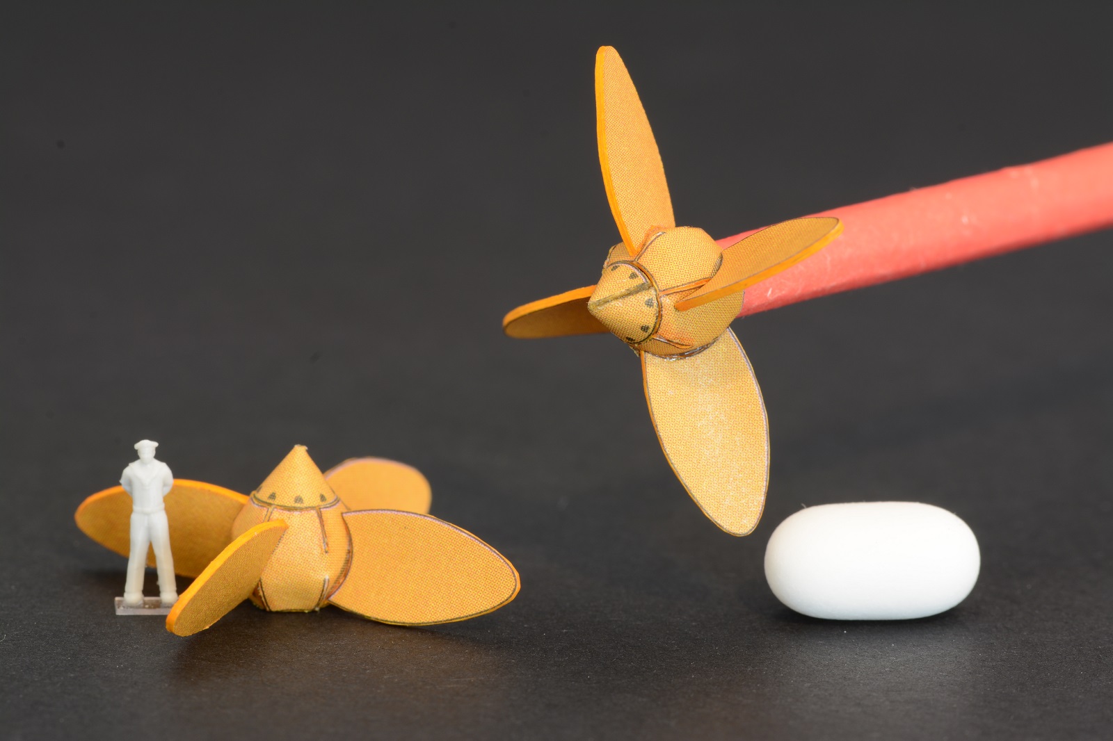
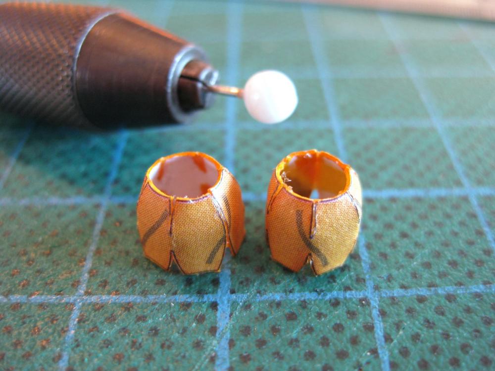
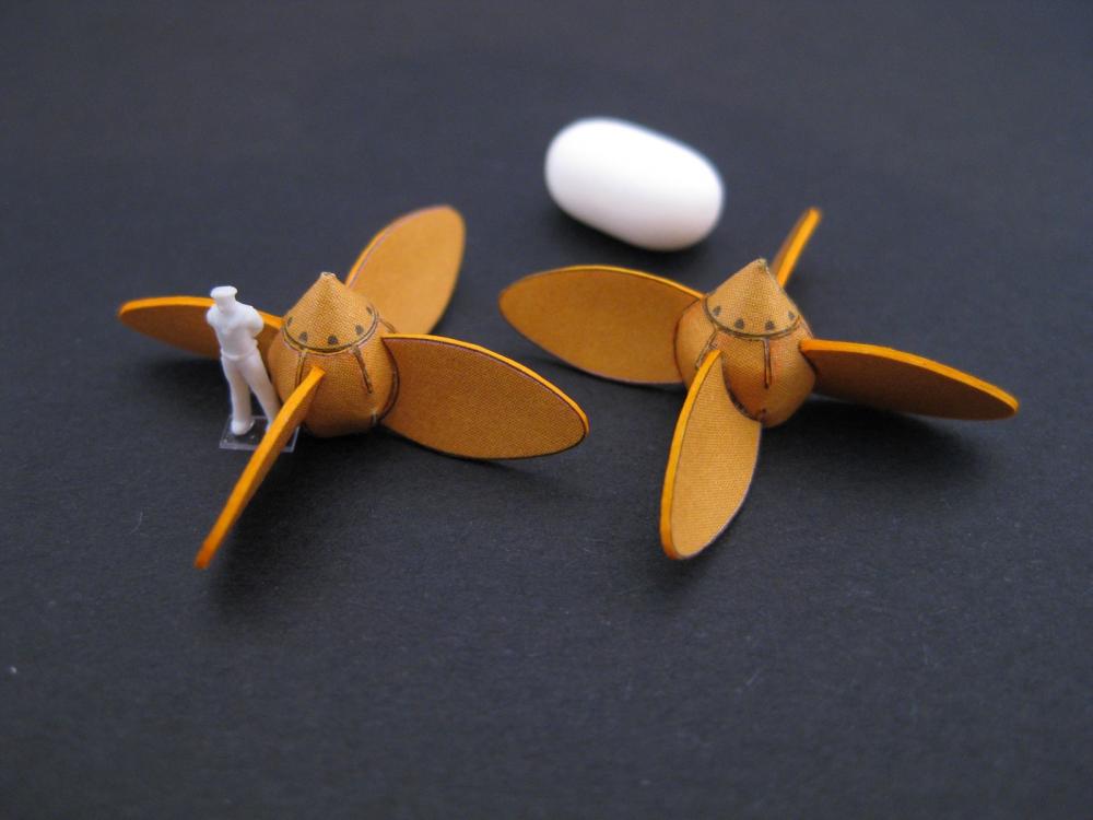
Hi Ken, hope it helps. I look forward to following your progress when you start again. Hi Grant, thanks for the comment. Sometimes I do prattle on but if it helps new comers like myself then all good. I must say when I started I had to go through lots of web sites and forums trying to find info as most build logs just cover progress and not how they did it. Anyone starting up or thinking about starting up card modelling can’t go wrong by checking out Chris’s (ccoyle) excellent 8 part tutorial found on this site as per the link below; http://modelshipworld.com/index.php/topic/2701-intro-and-table-of-contents/ Okay here are the propeller hubs. These were my first attempt at this type of petal and were certainly the trickiest. With the hubs cut out I used the rolling with a smooth rod, a drill shank in this case, to progressively curve the ends round to meet each other. This was pretty straight forward. The difficult part was forming the petals inwards to glue to each other. If the petals were only on one end I would find a rod with the same internal diameter and round it off so the petals could be formed against this. Unfortunately the petals are on both ends to form an inflatable beach ball type of shape so this wasn’t possible. Necessity being the mother of invention I found glass bead pins held in a pin vice could be used to form the petals against. Not ideal but workable with time and care. The hubs all glued up. Not overly pleased with how they turned out as they are supposed to spherical Time to attach the blades done previously. I bent the blades against the handle of the craft knife to get a bit of a shape into them. They were simple enough to glue on but because the hubs weren’t fully rounded some blades have a gap in the centre of the root. There are coloured lines on the hubs to show where the blades glue to but I also used the square lines printed on the cutting mat to align the blades at right angles to the hub. Looking down through the hub I used the cutting mat lines like crosshairs to centre the hub and then used the lines extending from the cross hair to align the tips of the blades. After the blades it was just the end caps to attach and these were barely wide enough to sit on the end of the hub opening. Of course the holes in the ends of the hubs weren’t perfectly round so after applying glue around the hole perimeter and dropping the end cap on top It took a bit of tweeking, pushing in here and there to match the cap as best as possible. At least the paper prop shafts fitted!. For the photo the tube is slid along a piece of wire to hold it up and couldn’t resist blowing on the end…and it actually spun LOL…but would that be full astern?! The full macro shots look pretty awful to be honest and I resisted showing them, but saying that for a first attempt and at normal, to fairly close viewing distance I think they are acceptable. Again their final home does prevent close scrutiny. I really need to skin the lower hull LOL Cheers Slog

- 244 replies
-
- 12
-
-
- borodino
- dom bumagi
- (and 1 more)
-
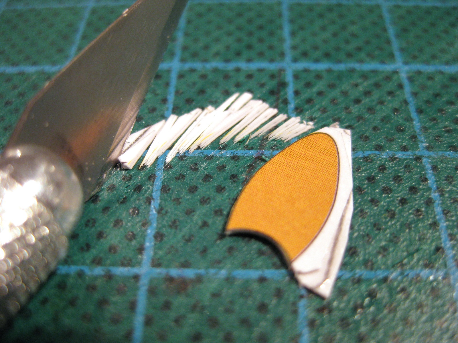
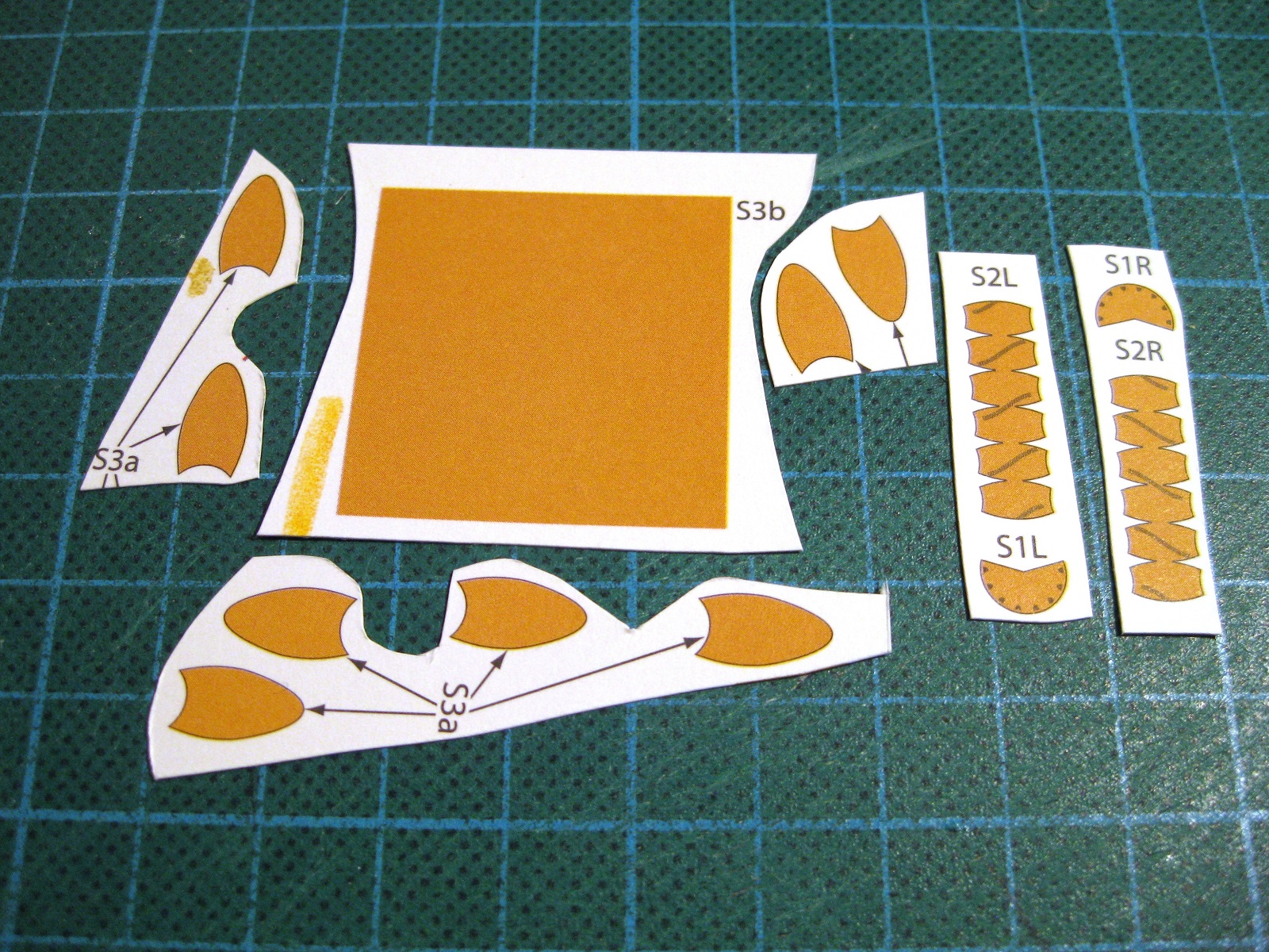
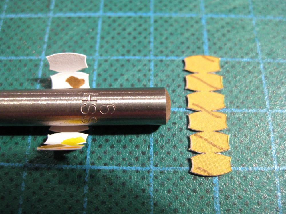
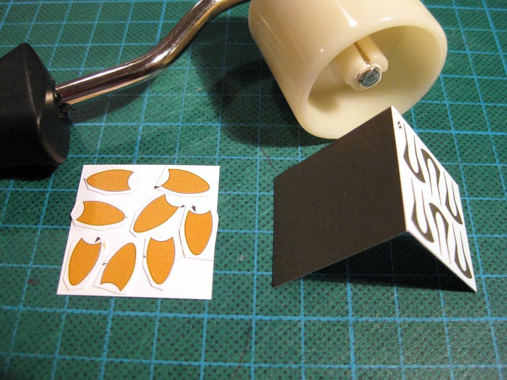
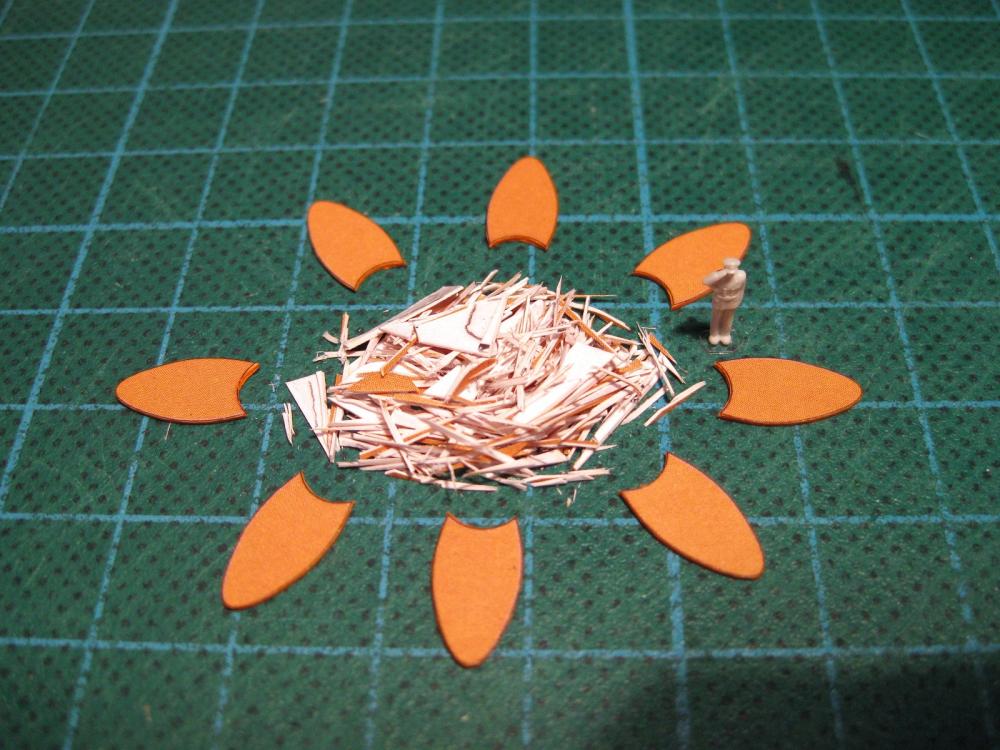
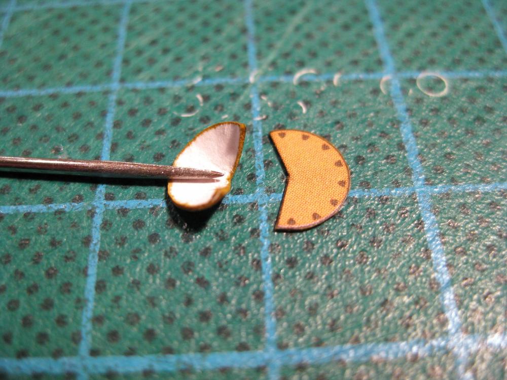
Hi Ken, you are correct in using only enough for the job. It is amazing how quickly PVA dries based on the small quantities used. I know what you mean about the hidden stuff LOL. For small parts such as vehicle wheel hubs or the propeller end caps covered above, once fully dried I will go back and dump a blob of PVA in behind them. Always surprised how it looks filled when wet but almost disappears when dried back. I don’t know if it really does anything but makes me feel better LOL Hi Chris, I will need to go back through your V108 tutorial again and check it out. A problem I have found looking for glues is you come across interesting or what looks like a good glue someone else has used only to find they are region specific and can’t be found locally. I guess sometimes legislation prevents them being imported based on the chemicals/ volatiles used in the composition. I know some black chrome guitar hardware can’t be imported to Australia because of the process/chemicals used to chrome them. I have come across non-stringy UHU glue but can’t find it in Australia. The search for the perfect glue continues! Hi Greg, with the guns it’s usually only the largest main guns (and maybe secondaries depending on calibre) which are made of paper. These are usually on thinner coloured paper which is rolled into a tube. The plans/diagram sheets will tell you the size and length to make the smaller barrels from brass rod. I do have the metal gun set but will attempt to roll the larger guns if for nothing more than giving it a try. Technically card models don’t need painting at all as the printed parts are all coloured (correction some of the Shipyard models are on plain paper and are supplied with paints I believe). For colour printed kits only the cut edges and/or backsides of parts which are visible but not laminated to other coloured parts need painting with one method or another. There is nothing stopping you painting a model if you chose. I weigh up what I want based on my desires, the quality of the printing or what others have done before deciding. My first card vehicle, which I am still working on!, I am building it straight from the book as the quality of the paper and printing is excellent but more importantly to gain experience. I need to be careful and precise since it is straight from the book. If I knew I was going to paint it then I would become sloppy and less careful knowing I can fill defects and hide it all with paint. I need the experience!!! Saying that I have another vehicle waiting in the wings which I WILL paint and weather as the examples I have seen by others are outstanding. Borodino I want to do also without painting, again for the experience and because I like the look the publishers have gone for. This takes us back to the guns; the brass guns will need painting and although the ship looks black the printing isn’t really a solid black colour so when sprayed up will definitely stand out from the ‘black’ paper hull. I have a few ideas to try and tone down the painted guns when I get there. The red lower hull may end up getting painted as this area is notoriously difficult to get right for a newb like me. I can live with that as long as that is the only part I end of painting. Okay since I have bored you all senseless a bit more progress to cover with the propeller blades and a couple more techniques for laminating and cutting curves. The prop blades are designed to be double thickness and the individual blades are laminated on to the big yellow square (swatch) shown in post #44. This is the first disappointment with the kit. I have several kits in my stash and all laminated parts are folded and glued in one operation. This kit needs individual parts cut out and placed on to the other coloured section. This isn’t a big deal with the prop blades as they are solid colours but the real pain is for small matched and mirrored parts. ( I will cover those in more detail when I come to them but simply, they have made what should be a simple process very difficult). The photo shows the individual blades cut out and arranged on the backside of the colour ‘swatch’ to check alignment before gluing. I have showed (on the right of the picture) a more normal process from another kit which you cut out parts and ‘swatch’ as one piece, score down the middle, fold and glue. A much more elegant way to do this! I think having the parts spread out instead of together is to make maximum use of the available paper areas to cut down on the number of parts sheets needed. I have another issue with this which I will cover further down the track Also shown is a 30mm diameter wallpaper seam roller I picked up cheaply from the hardware store. I brushed glue on to the back side of the ‘swatch’ and then placed the blades into position and then used the roller to press them down. Simple. I used to use a smooth knife blade handle to roll across the parts but having a roller with a handle is so much easier on the old fingers. Okay with the parts laminated together and fully dried it is now time to cut the individual blades out to shape. Firstly I rough cut them apart so I can handle them one at a time. You could cut the curves out free hand, which I did for the blade roots. In my opinion this works better for larger parts where you have space to hold and move the blade etc. I don’t like doing this on small and/or laminated parts. For cutting out small and/or tight curves, circles etc such as these I prefer to make many multiple slices, cutting off small slivers at a time. The technique I use is to hold the heel of the blade down on the mat and with the line under the edge, rotate the blade forward (keeping the heel down all the time) slicing on the line nearest the heel and cutting a wedge. Rotate the blade back on the heel and either turn the blade slightly in or turn the part slightly in and once aligned rotate forward with the next slice. Continue on round the part. The tighter the curve the more, smaller cuts are needed (such as at the tip of the prop blade). It sounds long winded and time consuming but once you get into and get a rhythm going it doesn’t take long at all. Another good thing is using a part of the blade rarely touched in card modelling so usually very sharp. It is important to keep the heel of the blade on the mat at all times to pivot on. Important note: Don’t use the technique used for turning square wood stock in to round dowels where you knock the corners off a square to make an octagon then knock these corners off to make 2 smaller corners and so on until round. If you do it this way you will find you have lots of small points which get to the stage where you can’t slice them off and end up with lots of tiny flats. Start the first slice and continue it round… The finished blades. I coloured the edges with a Faber Castell artist PITT pen #109, Dark Chrome Yellow which isn’t too bad a match. Once I have completed the hubs and got an idea of the final root shape I will put a bend into the blades to make them more propeller shaped. Cheers Slog

- 244 replies
-
- 10
-
-
- borodino
- dom bumagi
- (and 1 more)
-
Thanks for comments guys. With regards to glue I almost exclusively use woodworkers white PVA glue for paper to paper, paper to card etc. PVA glue is water based so care is needed not to make the paper soggy or warped. I use a small paint brushes, usually 000, or a needle held in a pin vice for applying small amounts to edges so rarely come across any issues. For large skins to be glued to card I use a larger flat brush but again spread a thin film rather than swamp the parts. Sometimes a part may prove troublesome in joining and in this case try to avoid applying more and more glue as the part will soften and deteriorate. If a part gives trouble usually best to leave it alone for a bit to dry out and stiffen up before trying to reglue it. Some excess glue may get on the printed surface and in cases like this a small paint brush, dampened ever so slightly with water is used to brush the excess off. Again care is needed so as not to damage the printed surface. Best though to use only as much glue as needed and not have excess squeezing out everwhere. I would like to try Aleens Tacky glue which a lot of our American counterparts use but have been unable to find it locally. I occasionally use CA glue to stiffen/harden a small part but don’t like this as the CA ‘wicks’ through the paper darkening the print. I have used this so I could harden the paper for drilling small holes in it to receive a brass pin. I have also used epoxy but this is to secure brass rods to the card structure and is always covered. European builders, particularly Eastern Europeans use solvent based glues which don’t affect the paper with moisture. I haven’t really looked into these as they appear to be rubber cements or contact adhesives where both sides are coated and brought together and grabs immediately so only get one chance. I may be way off track here and happy for someone to correct me and indeed always looking to try new (to me) glues. I have tried UHU glue which is another popular choice for Europeans. It is clear out the tube and very thick and drove me nuts with the stringiness of it and it also appeared to just sit on the surface and skin over. I may try it again but unlikely. Again I may have been using it wrong (?) and happy for someone to correct me. Cheers Slog
- 244 replies
-
- 6
-
-
- borodino
- dom bumagi
- (and 1 more)
-
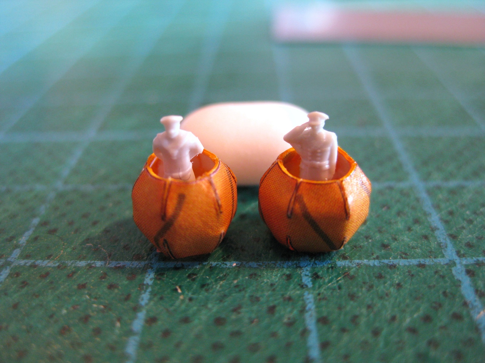
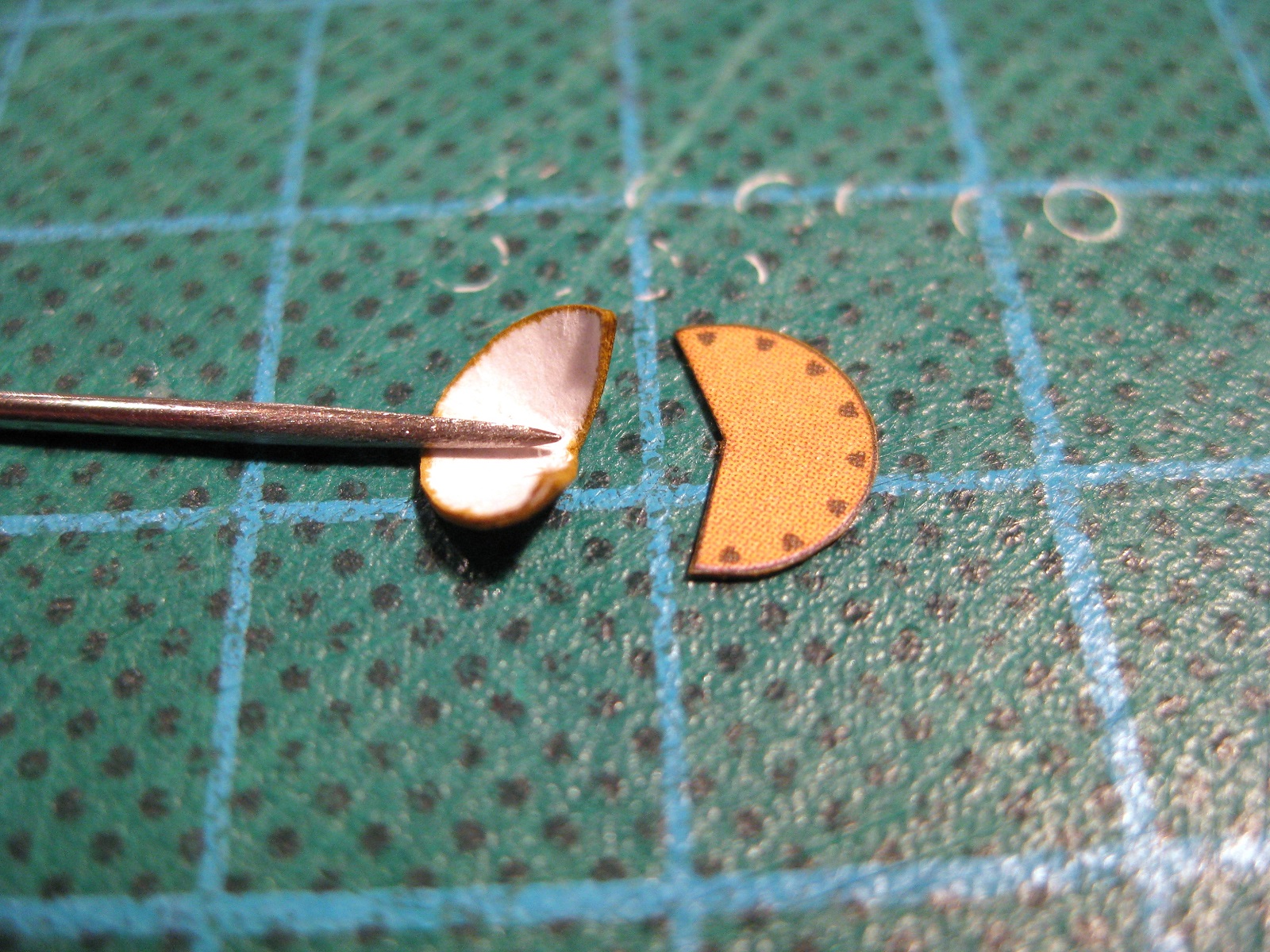
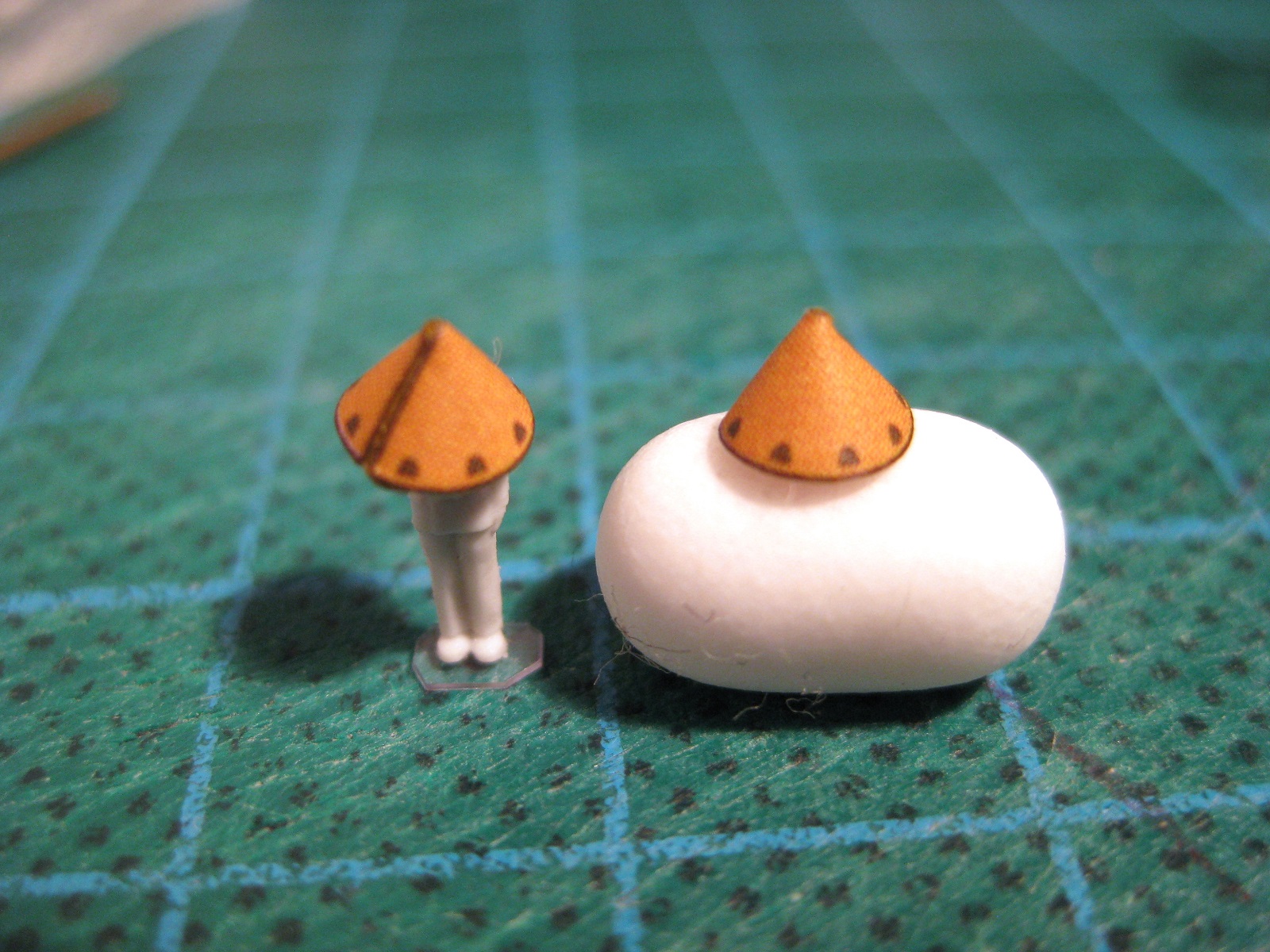
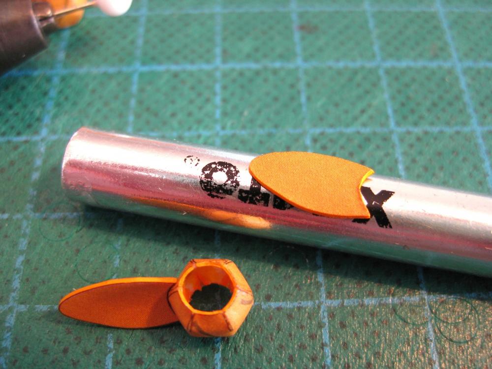
Hi all, I am still holding off from skinning the hull until I have a solid block of time to work on it without interruption…well that’s my excuse and I’m sticking to it. So to keep moving forward I decided to do the propellers. Borodino has twin, 4 bladed props and these consist of the hubs, end caps and the blades. I thought these would be good to show as they have 3 typically encountered card modelling techniques; these being laminating, forming cones and forming curves using multiple petals. The photo shows all the parts rough cut out to make 2 props. First up are the end caps. Even without diagrams you know a circle with a segment missing is going to form a cone. The technique here is to use a rod of some sort to form the cone; the smaller the part the thinner the rod needs to be, in this case due to the tiny size I used a sewing needle. I do this by placing the part upside down (obviously) on the pad of my finger (you could use the heel or palm of your hand; it depends on the size of the part and the amount of curve) and then pressing the needle down on the part and rotating the needle around the apex of what will become the cone. You need to press against something soft with give so the part bends against the needle. Start gently until you get a feel of the amount of pressure needed to slowly work the bend into the part. Don’t go hard at it in case you put a fold or crease in it. Two important things to remember; always keep the point of the needle at the apex and at 90 degrees to the edge of the part to form it uniformly. If you have the needle at an angle the curve won’t be around the apex. Secondly you need to rotate the needle (or rod or whatever) as you move it around the outside from one side to the other. It doesn’t work so well if you ‘drag’ it around plus you’ll find the part may spin instead of bending round the needle. You could keep going until the edges are near enough together but I find the part starts to get overworked and edges start to soften and delaminate etc by the time this stage is reached so get it close enough. Once I think it is ready to glue I try holding it in different ways using fingers, tweezers etc and try and work out the best way to glue it without needing three hands and double jointed fingers; only once I think I am am comfortable will I apply the glue. In this case I held them between finger and thumb on one hand and used tweezers in the other to manoeuvre and hold the edges together. The finished end caps. I am actually pretty happy with these and although the macro shows a thick black seam (I cut outside the line ) the size of the caps are only a few mm and the seam is a thin line at normal viewing distance. Also a trick to remember is where to place your joins and seams when assembling the model. If multiple parts with many seams make up a larger assembly if possible align these together away from view as much as possible. I this case I will align the seam of the end cap with the seam of the hub and in turn align the hub seam with the propeller shaft seam made previously. Then when installing in the hull I will fit the whole lot with the seams turned down and in towards the hull so it would be virtually impossible to get an eye in to see any joints once the model was complete and on a baseboard. Next up will be the hubs. Cheers Slog


- 244 replies
-
- 12
-
-
- borodino
- dom bumagi
- (and 1 more)
-
Hi demetri, thanks for dropping by. I saw your torpedo boat in the other thread when you posted it, very nice. Perhaps you can start a build log of your current build. Hi Panama Port, in truth I have no idea how it would effect card models. I have Halinski's IJN Fuso battleship waiting in the wings and they have a couple of paragraphs in there instructions discussing temperature and humidity and basically say damp cardboard expands and dry shrinks which is not a concern for small elements but causes problems for larger parts. There example is a large deck shrinks by 0.6mm in a warm room and combined with the other parts a cumulative shrinkage of 2mm! occurred. But once moved to a cold humid room it returned to normal size. Sorry not much to go on with. Personally with my skill set (lack of) I don't think I need to be planning my modelling sessions based on room conditions. If you think the humidity would deteriorate the paper itself I don't know, perhaps someone more knowledgeable can chime in. Cheers Slog
- 244 replies
-
- 3
-
-
- borodino
- dom bumagi
- (and 1 more)
-
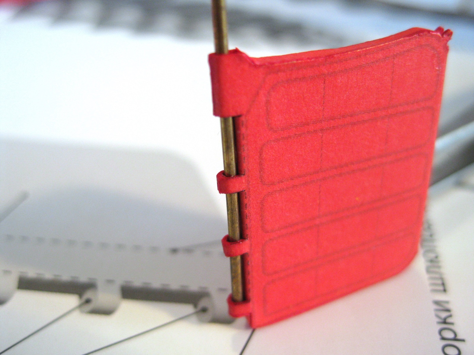
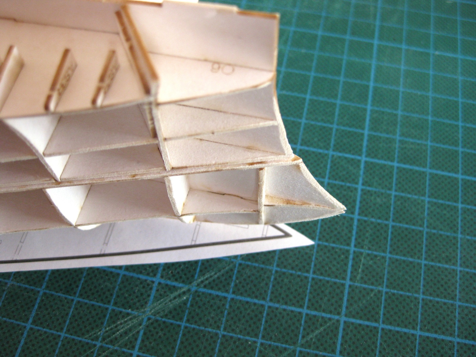
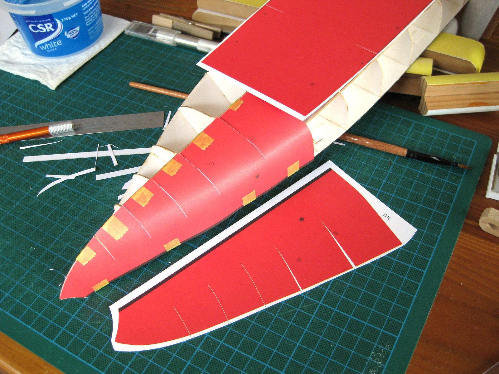
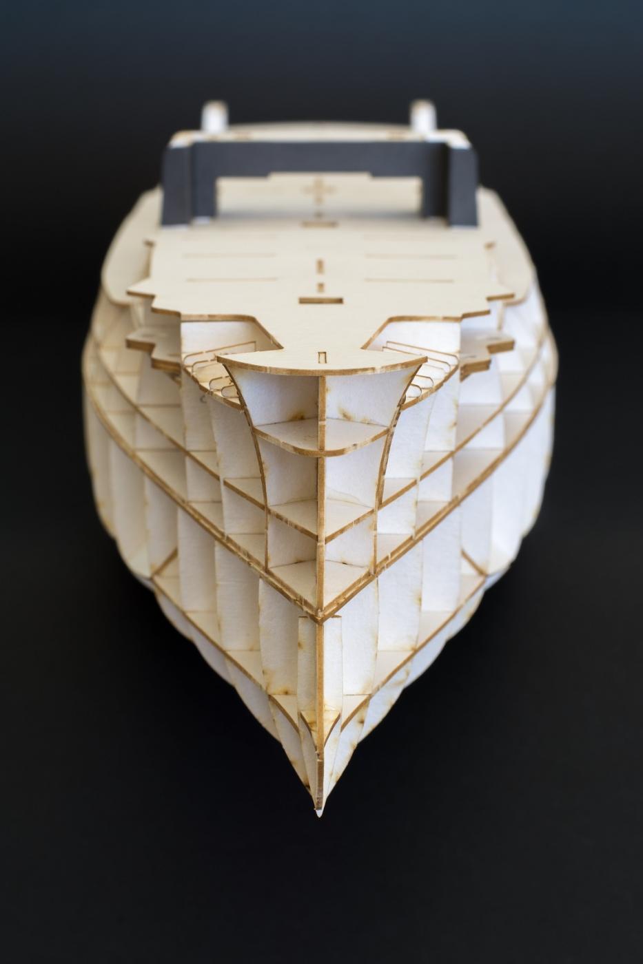
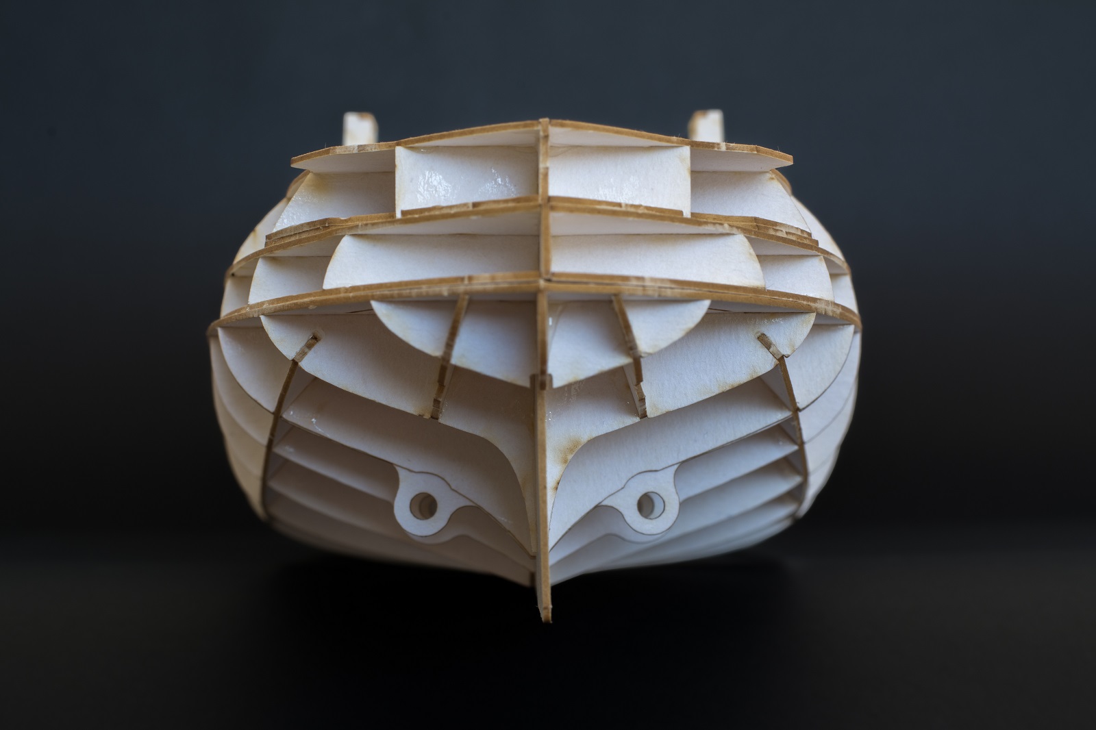
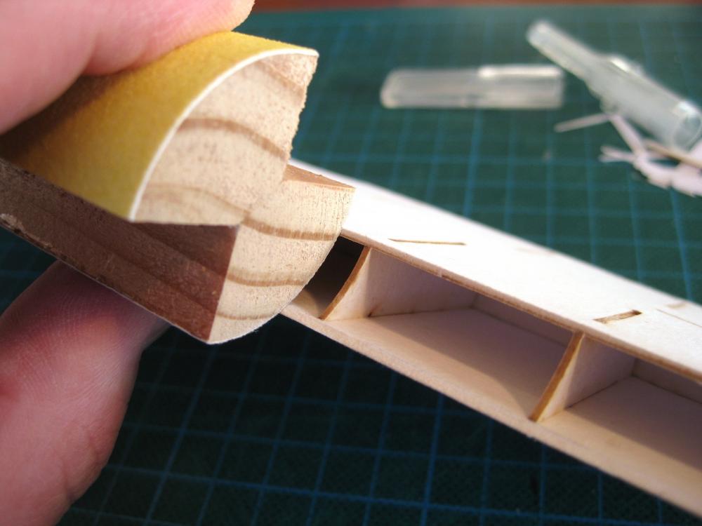
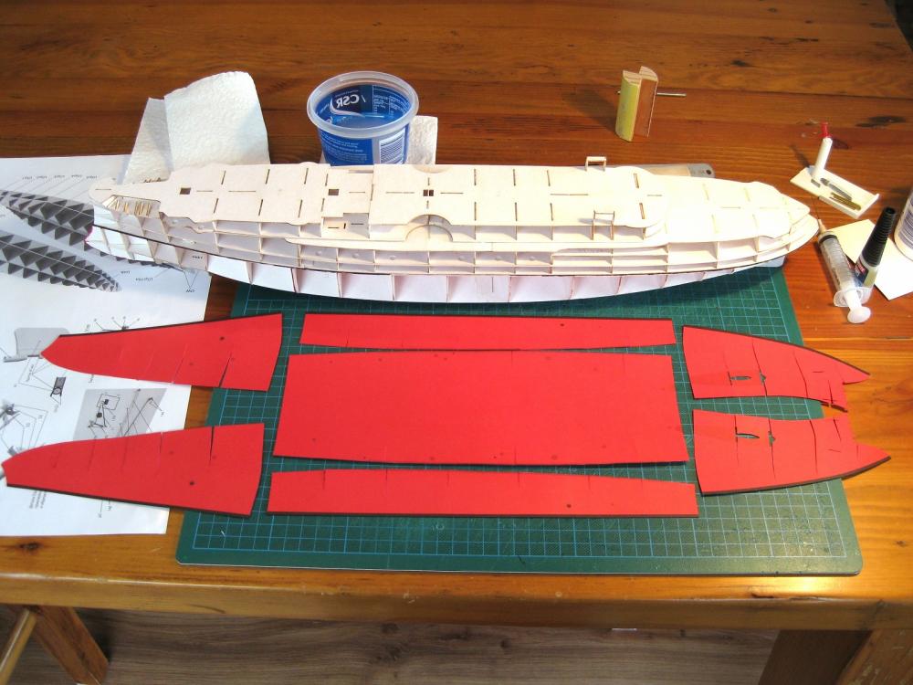
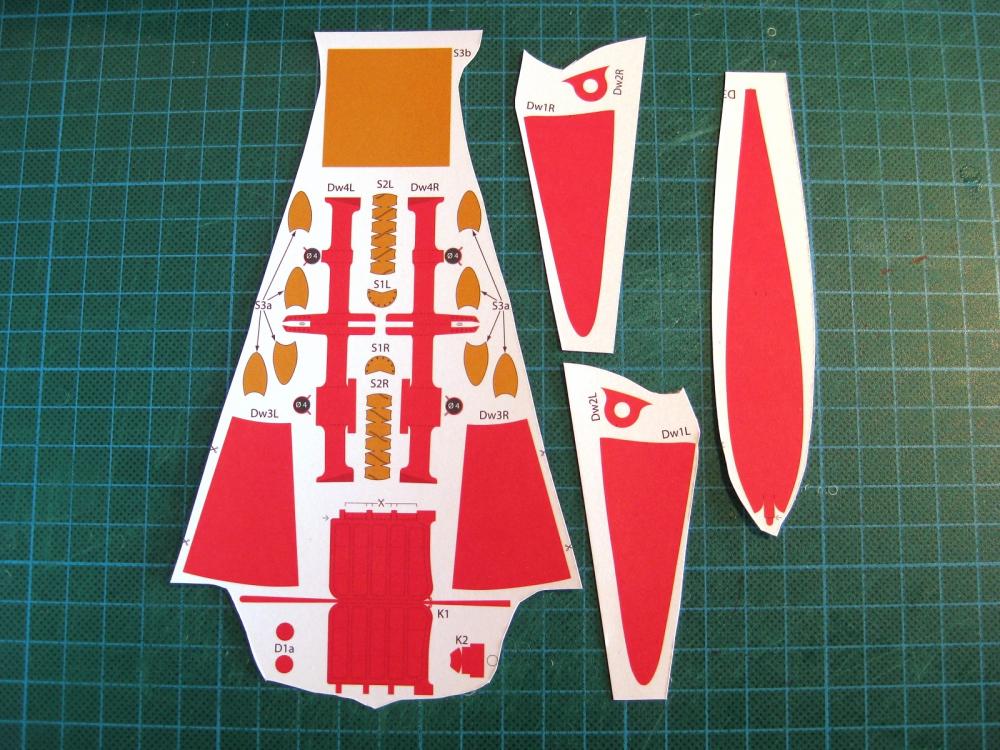
Hi all, thanks for the comments and likes. A bit of progress this weekend. Firstly I managed to finish off all the hull fairing; in particular the top deck section. The sides of the hull on this section are curved with the curve continuing down to the deck below. Because the laser cut forms are square edged these needed to shaped to suit. The object is to leave the bottom edge intact and bevel the former ends to the curve. I knocked the top edge off free hand with a craft knife and used a sanding block I made up years ago for something else. It consists of 2 pieces of 20mm wood quadrant glued together and has 400 and 240 grit sandpaper stuck on with contact adhesive. I chopped the quadrant to suitable sized lengths. As can be seen in the photo their a near perfect fit for sanding the decks to match the hull curve. The top section won’t be glued to the rest of the hull until the lower skins are fixed; there are a couple of sticking up parts which would get damaged when skinning the underside. Also the anchor shelves need to be skinned before fitting the top section. I spent a fair bit of time studying the plans and the parts and have finally worked out how the shelves are made up. After Chris’s comment about spraying the parts with matt spray I obtained Boyle Matt Spray Acid Free Clear Finishing Sealer from the local hardware store. I sprayed all the red lower hull skins with 3 coats. I haven’t done much to confirm it’s suitability doesn’t seem to had any adverse effects and will be interesting to see how they handle. One thing though was a part I sprayed already had cuts made in it and the pens I use for edge colouring had some trouble on a few edges. I just need to make sure I spray parts before cutting out in future. Okay here are all the major skins cut out. The seven parts are all that’s needed to cover the lower hull. I think I would have preferred more smaller parts rather than fewer large parts. The 2 rear ones have lots of cuts to allow them to form over the tight stern and I wonder how successful I will be in that area. Also I mentioned previously that the skins butt together rather than overlap so less wiggle room with that method. Here are the rest of the lower hull parts and include the propeller shaft bulges and supports as well as the props themselves. The lower part, K1 is the rudder and being a master procrastinator decided to build this next instead of continuing with skinning the hull. I enjoyed doing the rudder, having something manageable to form and glue up. The one part is cut out and folded to shape. Along the top edge a strip of 1mm by 1.7mm(!?) card stock (scrap from the laser cut forms) is glued on and the tabs folded over to form the front edge of the rudder. I am not sure but I think this card is slightly thicker than I am used to previously and suffers from the paper delaminating on small and bent parts. The tabs delaminated on folding over and I had to brush in PVA to fix. Also the small sticking up tabs form the hinge and these delaminated as well despite very little handling. The instructions show a 1mm hinge pin so 1mm brass rod was laid between the tabs. I applied glue to the tab ends and folded over the rod. Whilst gripping the sides with my fingers I used the sides and edges of tweezers to work and form the tabs together. Periodically I would twist the brass rod so that it didn’t stick to the glue and could be removed and inserted. The rudder bottom wraps round and up to close of the bottom hinge. The completed rudder. It is not shown if the top and bottom strips fit between or on top of the rudder sides. I decided to fit them between for a cleaner side view but I actually think they should lie on the rudder edges as it was a bit tight getting them in there. There is still a small rudder shaft top (K2) to do. I’ll know better when the stern skins are on but hoping I can form their hinges the same way and then insert the rod to join but not sure if this is possible which may mean trying to form the stern hinges round the rod with the rudder attached which is going to be a pain. Cheers Slog
- 244 replies
-
- 11
-
-
- borodino
- dom bumagi
- (and 1 more)
-
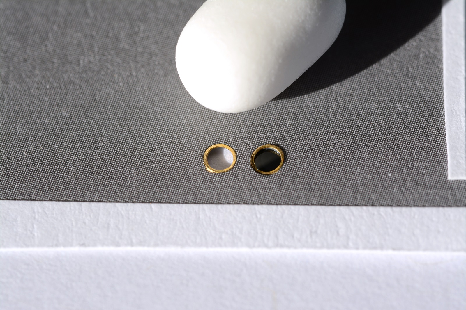
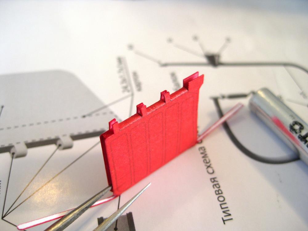
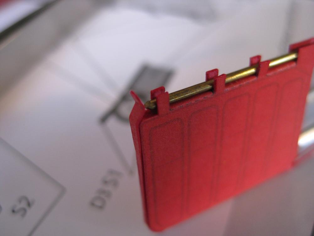
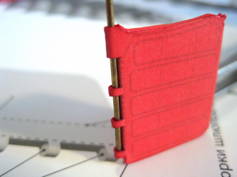
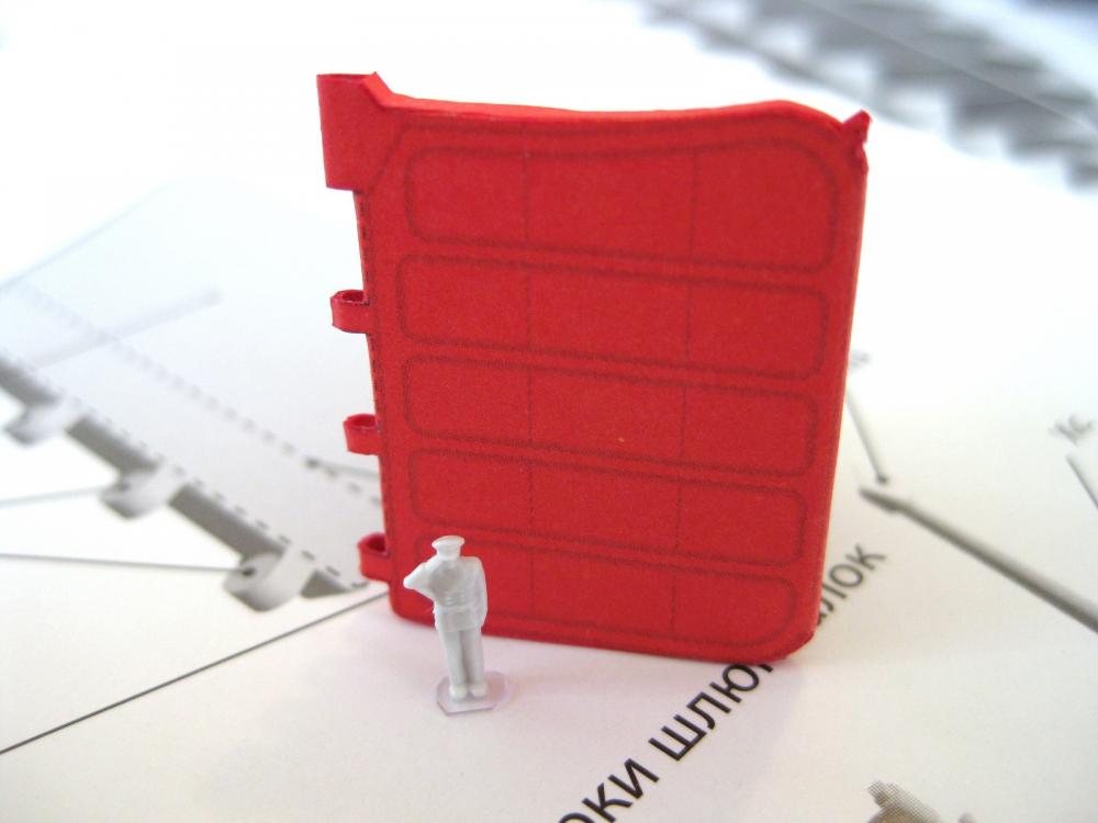
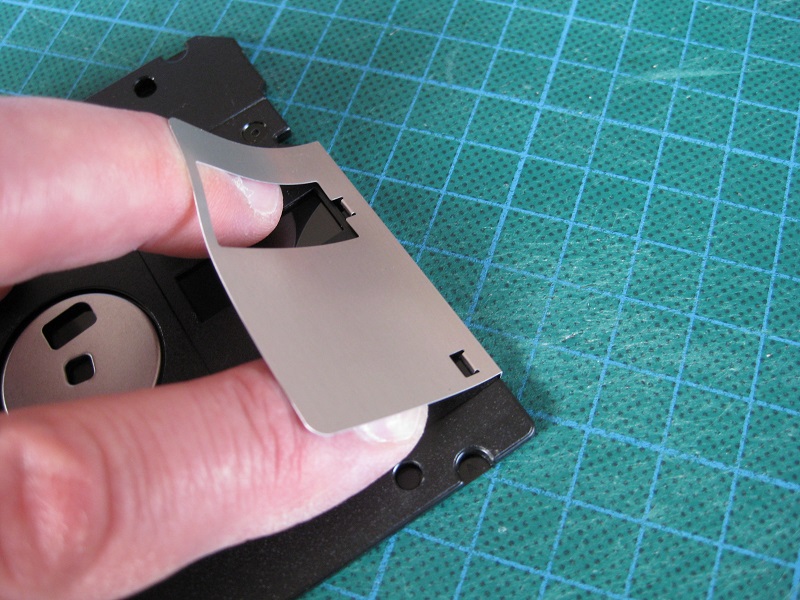
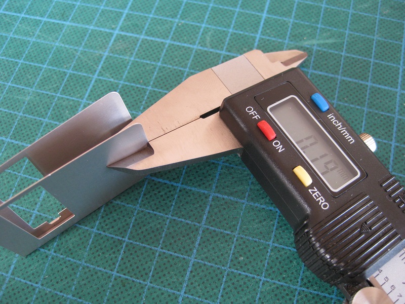
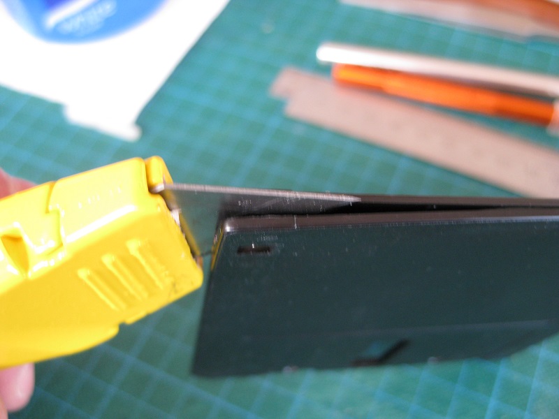
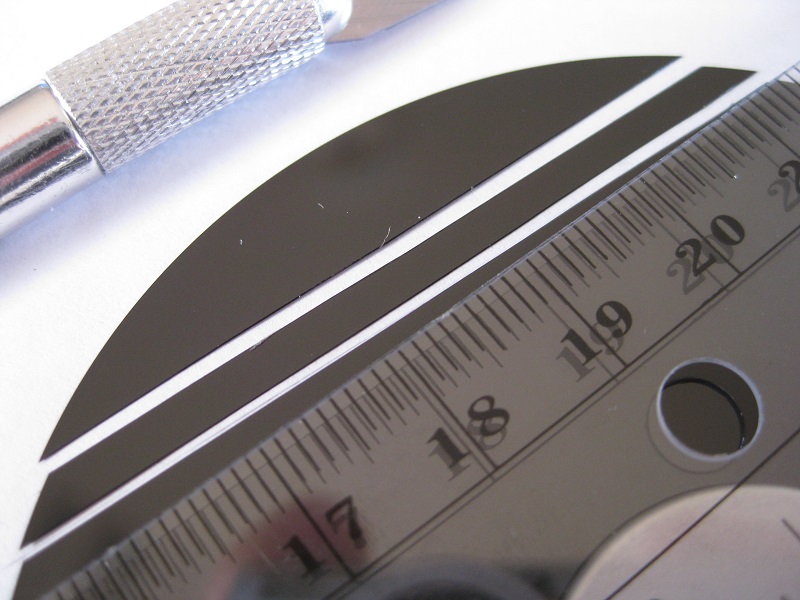
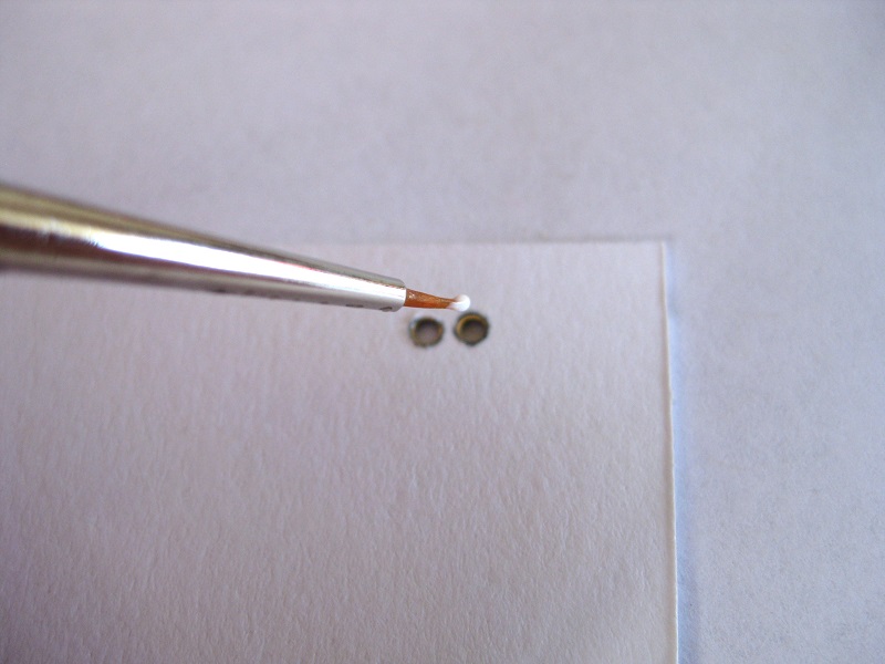
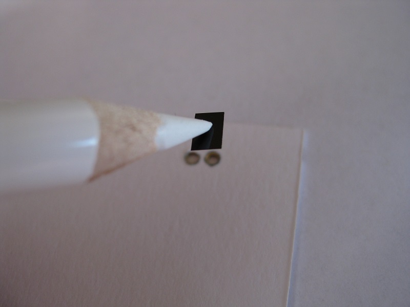
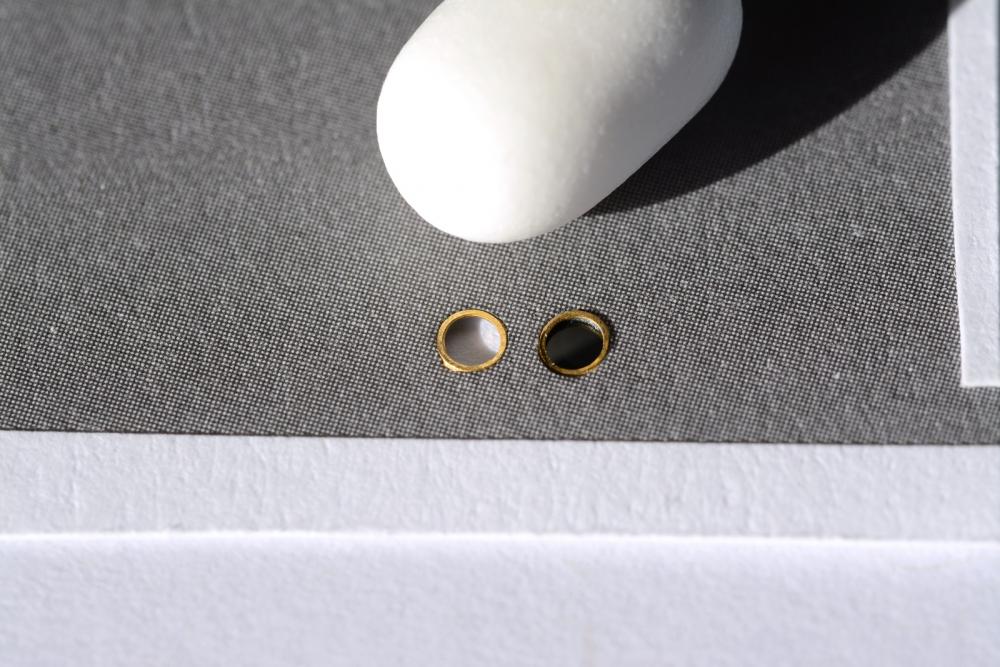
USING 3.5" FLOPPY DISKS FOR WINDOW GLAZING (NO SCALE) Hi, CaptainSteve asked if I would do a post on using floppy disks for window glazing after he saw it on my Borodino build log so here it is. Firstly, I would usually give credit to the person whose techniques I use and post on my build log but in this case I am afraid I have no idea where I picked this up from as its probably been a couple of years but only using it now. The floppy disk could be used to ‘glaze’ stern galleries and quarter light windows as well as portholes. My example is for 2mm photo-etch portholes in spare card that came with an other model I am building. It could probably be cut to fit between the transoms and munnions on larger wooden or photo etch frames. It is easier to just cut it oversize and glue from the back and in the case of the portholes the best method (probably the only method). I would imagine most people have floppy disks lying around in the house somewhere. It’s probably well over a decade since I owned a floppy drive to read them. If you haven’t I would imagine you could still source them from the internet maybe. Firstly remove the metal door from the case. If you don’t want to keep it just rip it off. Since it’s nice and thin at 0.19mm (slightly thicker than photo-etch I wanted to save it in case something comes up where I could use.) Prise it up from the backside of the case to lift the 2 tabs out of the groove. Once clear of the groove it drops off. To get to the floppy part I pushed a Stanley knife blade into one of the joins at the corner. The case is glued (plastic welded?) only at the corners so you want to cut this bond free. Then do the same at another corner. You only need to do 2 corners then you can pull the case open until the disk drops out. The disk itself is actually pretty amazing. I thought it was made of Mylar and CaptainSteve confirmed this, also informing me it was coated with iron oxide. I used my Vernier to measure it and it was 0.08mm which agrees with CaptainSteve’s 0.003” It is very tough; I was unable to tear an undamaged disk by hand. The disk is very shiny and some care should be taken to avoid marking the surface; probably not a big deal on 2mm portholes but you don’t want any blemishes showing up on larger stern gallery windows. I also avoided touching the surface with fingers to avoid leaving finger prints for the same reason. With this is in mind I used a plastic school ruler as opposed to my usual steel rule. To cut it with say a No.11 blade I found it best to hold the knife at a very shallow angle. I prefer to use small super sharp scissors to cut it as I don’t need to cut out accurate dimensions and they don’t burr the edge which sometimes happens with the knife blade. To glue the window ‘pane’ I use normal PVA. This is more than adequate for securing the part to paper and photo-etch; wood also I would imagine. As with most things less is more when gluing and I usually use either a sewing needle held in a pin vice or an old 000 paint brush for applying glue. I used the paint brush in this case as I need to spread it out on the back surface of the ‘model’. I guess most glues would be suitable and you will need to experiment for yourself for your glue of choice; I will add I wouldn’t use CA glue. I know CA glue fumes can fog up clear styrene canopies etc so as an experiment I placed a drop of CA on the disk to see what would happen and it did slightly discolour the edges of the glue blob. To fit the window I used a photo-etch parts placer. It is basically like a pencil with a hard waxy crayon centre. You can sharpen it to point using a knife or pencil sharpener and with use it loses its tackiness so you can resharpen it again but I usually just give it a quick scrap with an old blade. If you do a lot of photo-etch it is invaluable and has the benefit over tweezers with flat pieces as you don’t need to worry about trying to grip the part on the edges. Try not to slide the ‘pane’ around when placing as you don’t want glue smears/blemishes on the part spoiling the effect. The finished porthole next to an unglazed one. With the macro you can see a shiny window and even at normal viewing distance a dark shine is noticeable so would imagine the effect would be even more pronounced with larger scales and windows. Now if I could only find the same disk material but transparent all my window glazing needs would be met LOL Cheers Slog
- 396 replies
-
- 9
-
-
- Idea
- Bright Idea
- (and 1 more)
-
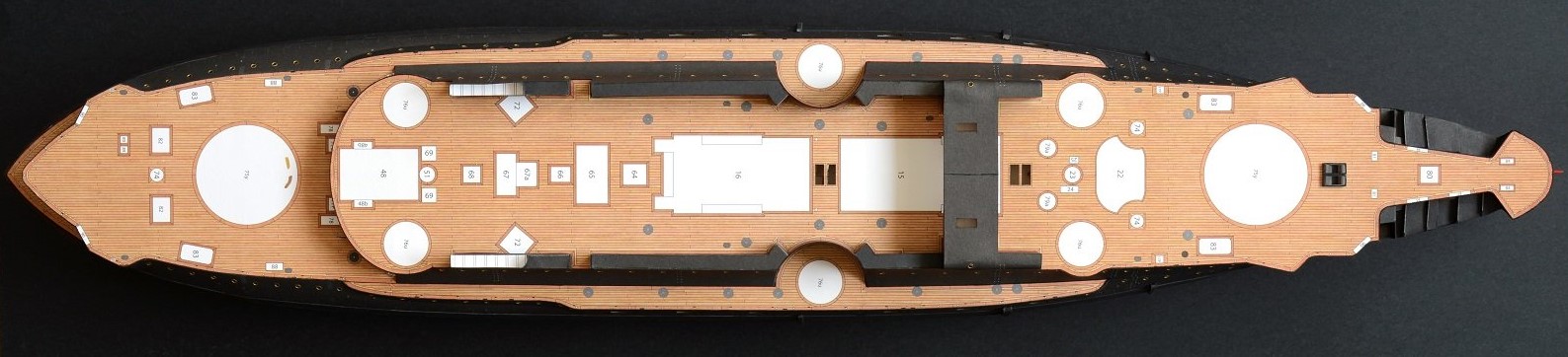
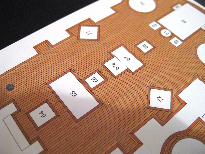
Hi Chris, Thanks for the info, I had a quick look around and although I couldn't find the Krylon brand close by I did find a few different brands of a similar product so will look further in to it. It does raise a question though. For attaching say, the deck furniture to the deck as per the numbered areas in the photo below would my usual use of PVA still work with the coat of Krylon? Cheers Slog
- 244 replies
-
- 5
-
-
- borodino
- dom bumagi
- (and 1 more)
-
Hi Jeff, Thanks for the comment. They didn't turn out to bad despite the struggle I had LOL Hi Mumin, Thanks for the advice. I have heard of this technique but don’t know much about it. I wasn’t sure what people used and the method of application. My concern with doing whole sheets or even large parts was how to get even coverage so there aren’t any streaks or discolouration due to uneven application. I also wondered on how the parts would behave when bending, cutting, gluing etc but from your comment this seems a popular technique so my fears are probably unjustified. I have brushed on Humbrol Matt Cote (a clear matt modelling varnish similar to Testers Dull Coat) to parts in the past (Orlik Mazur D-350 I am also currently building) but these were small wheel parts and already cut out. I coated them to try and prevent damage to the edges due to the amount of handling they were receiving. I found some parts a struggle to put together and they were getting handled far more than I am comfortable with. I haven’t the courage to use the Matt Cote on large sheet parts in case I destroy them LOL I was also thinking about airbrushing completed assemblies with Humbrol Matt Cote but again this would be after assembly. I will check out the product you mentioned and see how it compares locally. Cheers Slog
- 244 replies
-
- 6
-
-
- borodino
- dom bumagi
- (and 1 more)
-
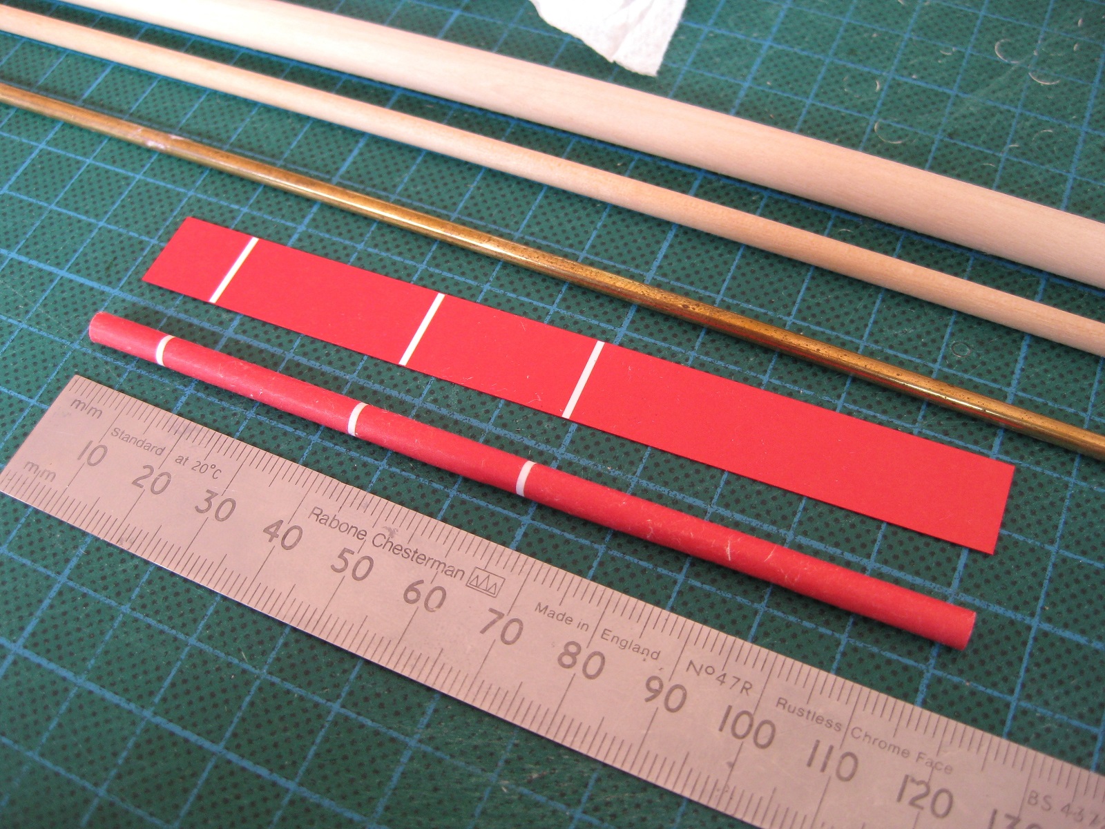
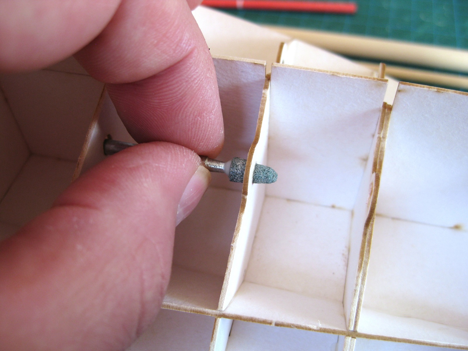
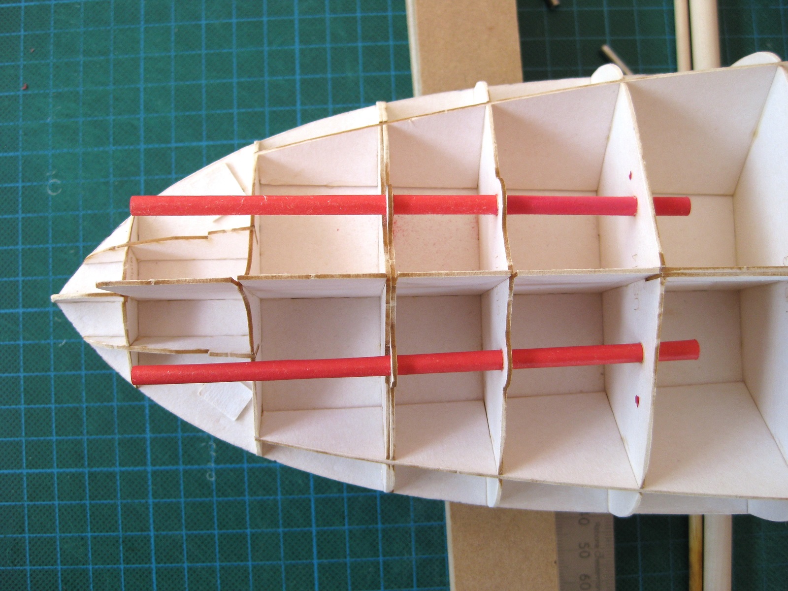
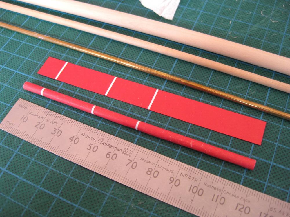
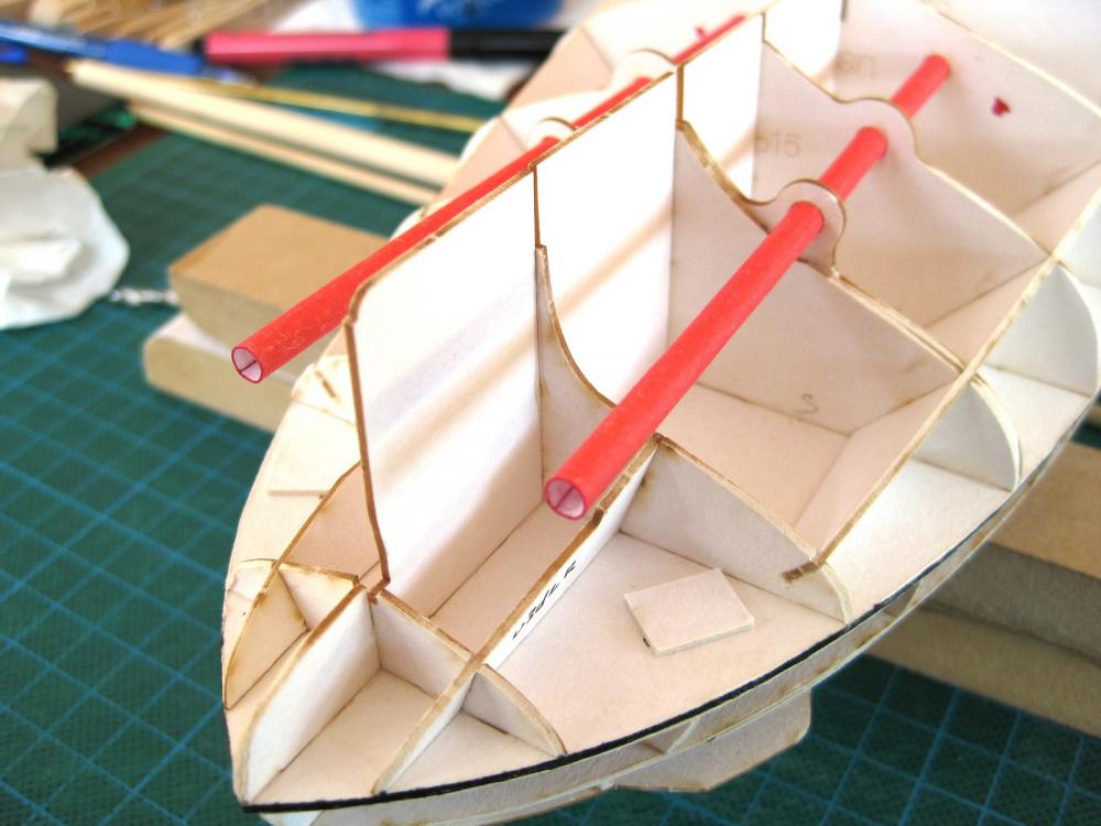
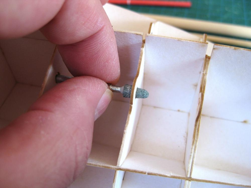
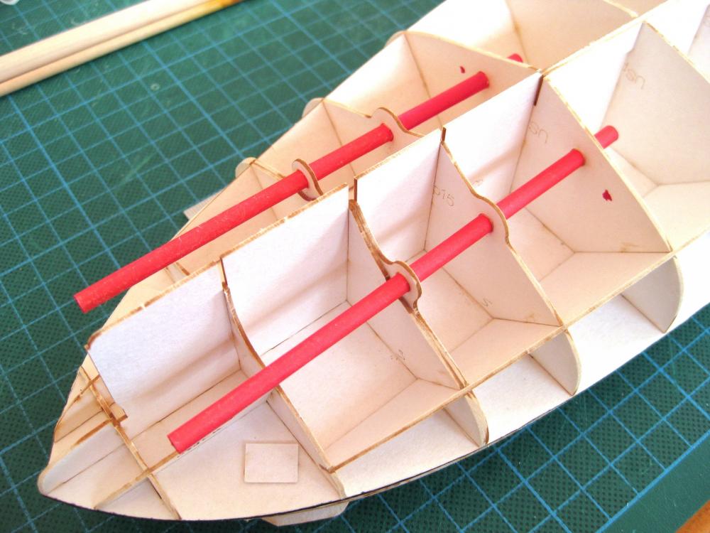
Some more progress. I am determined not to jump about and get distracted from skinning the lower hull, which is definitely the hardest part of the build for me and looking for excuses to put it off LOL. So I decided to do the propeller shafts which according to the plans need to in be inserted in to the hull prior to skinning the lower hull. I could cheat like I did for the Bismarck and use wood dowel but decided to use the paper part as doing is the only way to learn and hoping not to resort to painting the hull if at all possible. I had already started before I remembered to take pictures so the photo shows a completed shaft with the other one to do. I mentioned previously about minimising the handling of paper parts as they turn scrappy very quickly, well this tube shows the outcome of lots of handling. The first tube took about an hour of forming round various rods and dowels until the final shape was achieved for gluing. The second only took around 40 minutes to form and glue and wasn’t so tatty. The white bands on the part are used to align the finished tube with the hull bulkheads as shown in the other photos. As can be seen further on the alignment marks on the printed surface line up perfectly with the bulkheads. The legend next to the part shows to roll it around a 4mm diameter form… 4mm is far too wide and the edges are far from coming together. (the thin wood dowel in the picture is 4mm). So used various sizes at hand to gradually form the bend and finished off using the smaller brass tube which is quite a bit less than the paper tube internal diameter. Once I got the edges together I over lapped them to tighten the bend to remove some of the 'spring' of the paper and taped it like this a while. It was then a case of removing the tape and of course it opens up again; then gluing a short section together and holding until sufficient to let go and then applying a small strip of Tamiya tape to hold before moving up the tube and doing another small section. The first tube had a mishap whilst removing a small strip of Tamiya tape where it pulled some of the print off. (I think some glue must have snuck out on to it) The laser cut holes in the bulkheads were slightly too small so I used a Dremel, cone shaped grinding stone to ream out the hole until the tube was a tight fit (this was done by hand twirling the shaft of the bit with my fingers). This worked well slowly sanding out the hole; a drill bit would just catch and tear the card. The tubes turned out straight and near round with no creases or kinks so happy with that just a pity about the printed surface. I may be okay though as it appears most of the exposed shaft is covered by bulges and only the last 15mm or so is exposed. I tested some watercolour paint, which is a bit redder than the print on the end of the back tube and not very clear in the photos. Considering how much is on show and the position low down under the hull I can live with that. Cheers Slog

- 244 replies
-
- 16
-
-
- borodino
- dom bumagi
- (and 1 more)
-
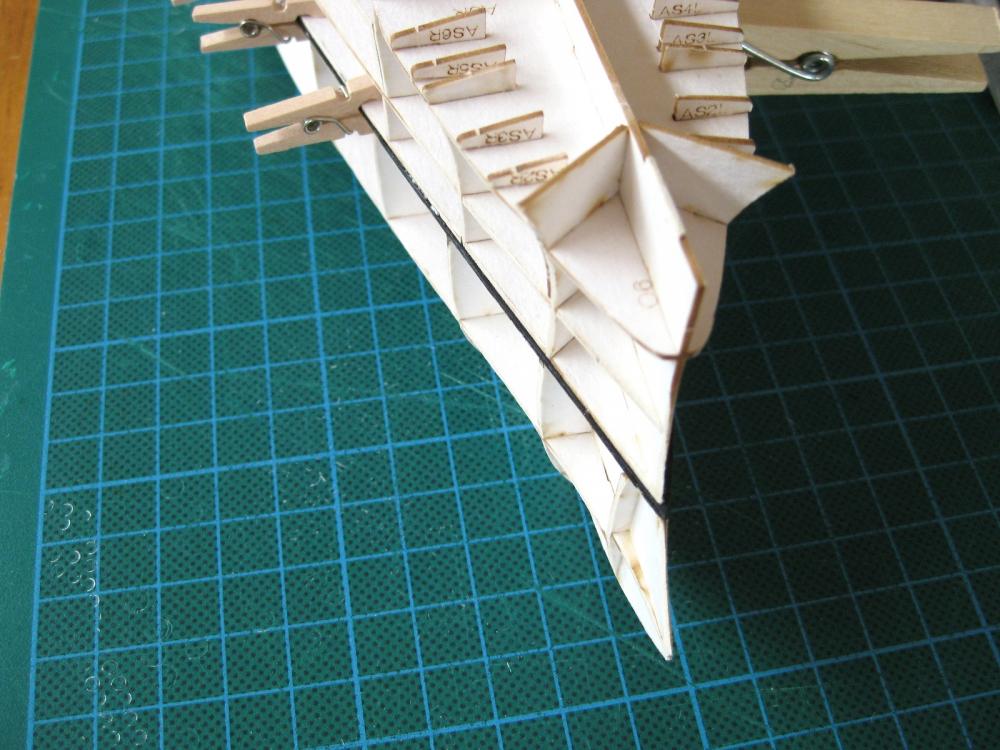
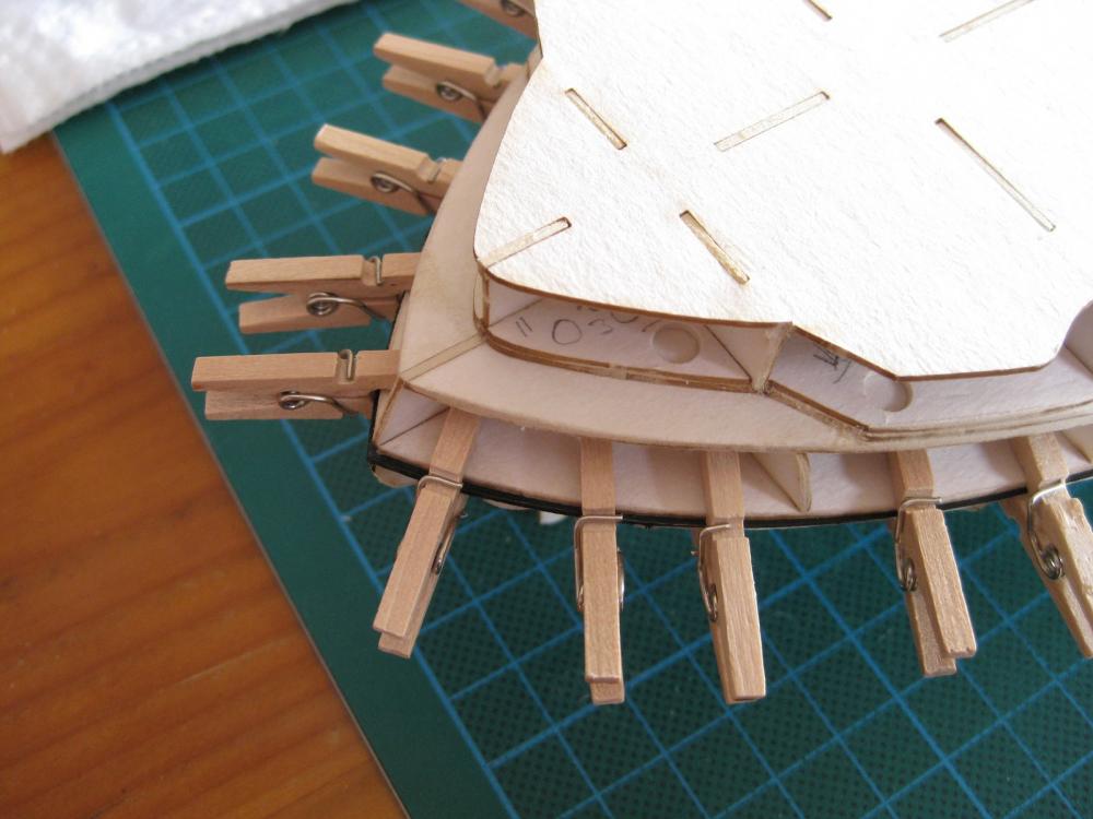
Thanks all for the comments and likes. This is a bit of a boring post today. Spent the day fairing the lower hull and the middle section and found when placed together there is a surprisingly large lip/ledge all the way round particularly at the stern. I assumed that the hull would be flush all the way down. I went to check the lower hull templates as I didn’t need these due to using the laser cut forms and the lower deck has a black border which wouldn’t be there if not to be seen. A couple of photos showing the ledge between the hull sections, which prompted investigation; and the template below them. Glued the template to the lower hull and then glued the middle section to the lower hull. The paper template is very thin and already starting to get a bit tattered at the edges with handling. I used an artist pen to touch up but then got damaged again with the Tamiya tape as used further on. Once the lower hull is skinned up I will go round tidying it up before skinning the upper hull. I will use paint and matte coat to toughen it up. Time to start skinning the lower hull. The skins were initially rough cut out to get an idea of how they fit together and then started to trim the first of the bow skins. A couple of points of note; firstly the colour does appear to be quite a bright red. Initially I wasn’t keen on it but starting to like it and I think when the primarily black hull and structures go on should complement each other nicely. Also the method of skinning relies on only a few quite large pieces which require slices and sections cut to allow them to curve around the hull to fit. My minimal experience of hull skins use more multiple narrow bands so shall see how these compare. Also it appears they don’t overlap so butting large skins together may be problematic. The skin in the photo is just attached with strips of Tamiya tape to see how it forms round the curves. Initial trial fitting of bow skin doesn’t seem so bad, there are tiny little marks for lining up the skins to the forms and on first try they appear to match very well. What I will do is put some card on both sides of the forms where separate skins join as although the trial fit seemed perfect it wouldn’t take much misalignment for them to run off the narrow formers. I tested a few ways of edge colouring using 2 different red pens and some water colour paint. I will end of using the usual Faber Castell PITT artist pens (Carmine 126) as although it looks quite pinky it is actually a darker red than the print. Next up will be to trim all the lower skins to size and then offer them all up together before gluing. Cheers Slog

- 244 replies
-
- 14
-
-
- borodino
- dom bumagi
- (and 1 more)
-
Awesome work. I particularly like the close ups of the bridge area. So much 'busy' ironwork going on really makes these ship so interesting. Can spend an age just studying all the little bits and pieces. Very inspirational. Cheers Slog
- 342 replies
-
- 4
-
-
- dreadnought
- zvezda
- (and 2 more)
-
Hi Jeff, Nice work on the chains. I enjoyed doing the same on my Endeavour. Cheers Slog
-
Hi Daddyrabbit, Looking forward to watching your progress. I love photo-etch, it brings so much to a model. Cheers Slog
- 75 replies
-
- 4
-
-
- scharnhorst
- dragon
- (and 2 more)
-
Hi Joe, No, I didn't progress any further than what is in this log and ended up giving it away to a local Perth forum member. Cheers Slog
-
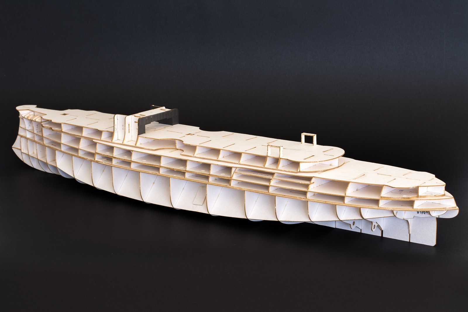
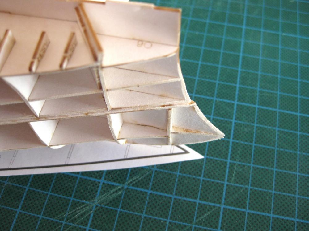
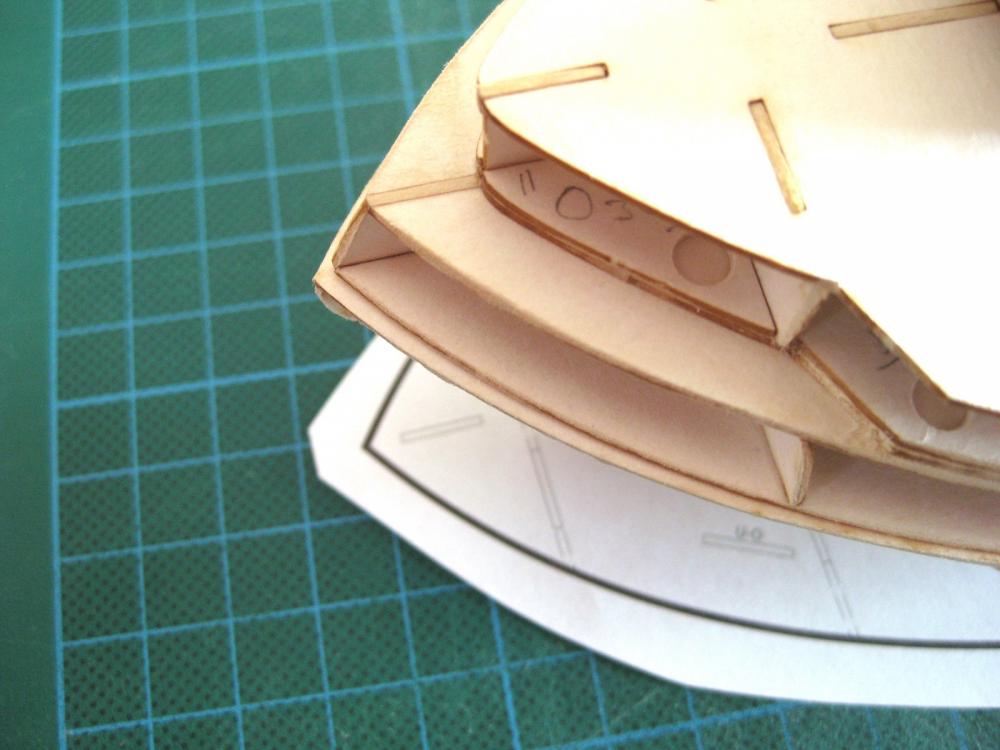
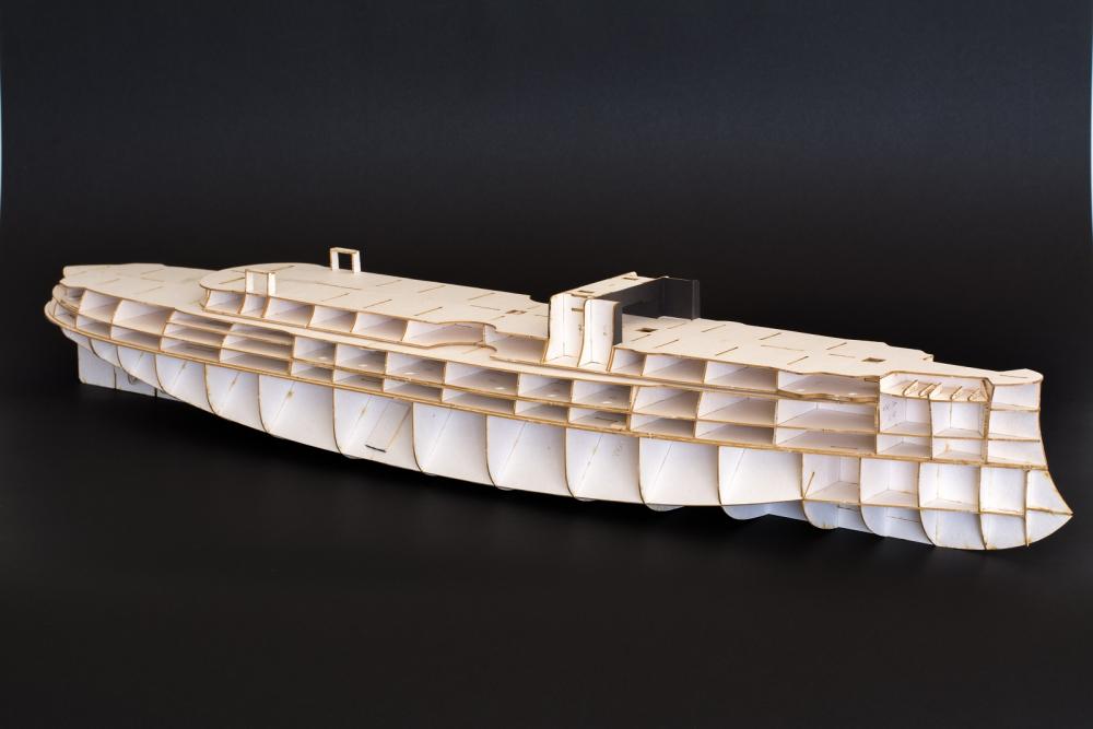
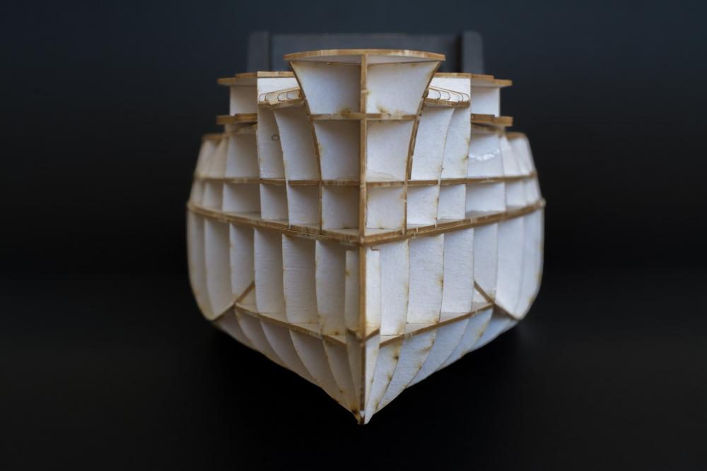
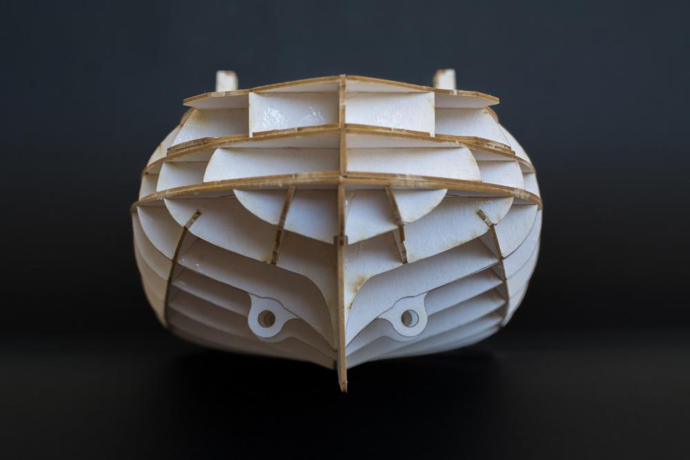
Hi David and Joe thanks for the comments, I am glad you are getting something out of it. I thought I would go into a bit of detail with the methods and techniques I use to hopefully provide an insight to card modelling. Also in the hope of prompting suggestions for better or alternative ways of doing things as I am still a newb when it comes to card modelling. Hi Paul thanks for the comment. I find card modelling very rewarding. The lack of mess compared to working with wood is also a bit plus for me! Also the vast range of subjects available is incredible. Doris’s work is exceptional and I could never hope to get anywhere near her standards. Just a small update as I have now finished the hull structure (almost) with all layers being glued up. I haven’t glued the 3 separate layers together just yet as I want to do some fairing and shaping, which will be easier done separately. Once that is done I will join all the layers together for a final fairing of the layer joins and then on to the dreaded hull skinning. Post hull structure analysis; On the whole I am very impressed with the design of the forms. They went together perfectly and the design creates a well-supported and rigid structure. A couple of other nice touches are a laser marked bearding line for sanding the bow to a sharp edge. Also the lower 2 sections have laser cut slots which align vertically with each other so that you can put in your own tabs from scrap to perfectly align the sections front to back and side to side. Couple of minus’s would be the lack of assembly detail as the diagrams aren’t very big and the numbering wasn’t clear which could have resulted in some of the double ribs being put in the wrong way round. The skinning of the anchor deck has me stumped which I blame the diagrams for. Rather than plough on with hull I decided to leave it for a bit of a change and do some of the top side structures. These run down each side of the deck and since they are flush with the edge, the hull skins extend up to cover them so they will need to be done sooner rather than later anyway. Cheers Slog


- 244 replies
-
- 18
-
-
- borodino
- dom bumagi
- (and 1 more)