
Captain Slog
-
Posts
904 -
Joined
Content Type
Profiles
Forums
Gallery
Events
Everything posted by Captain Slog
-
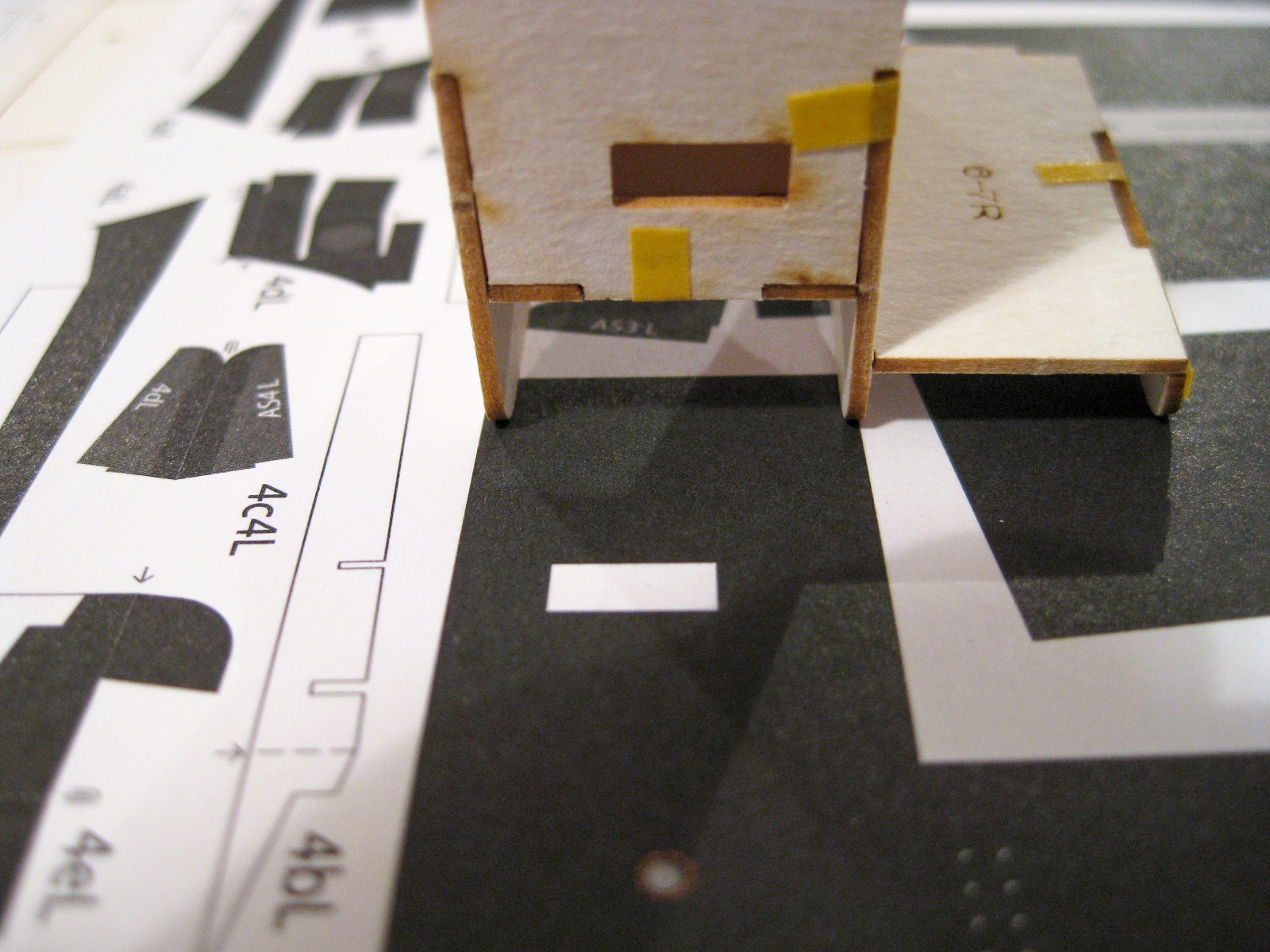
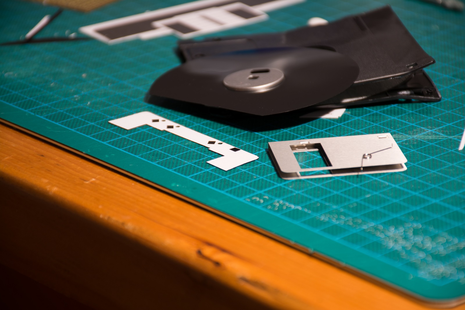
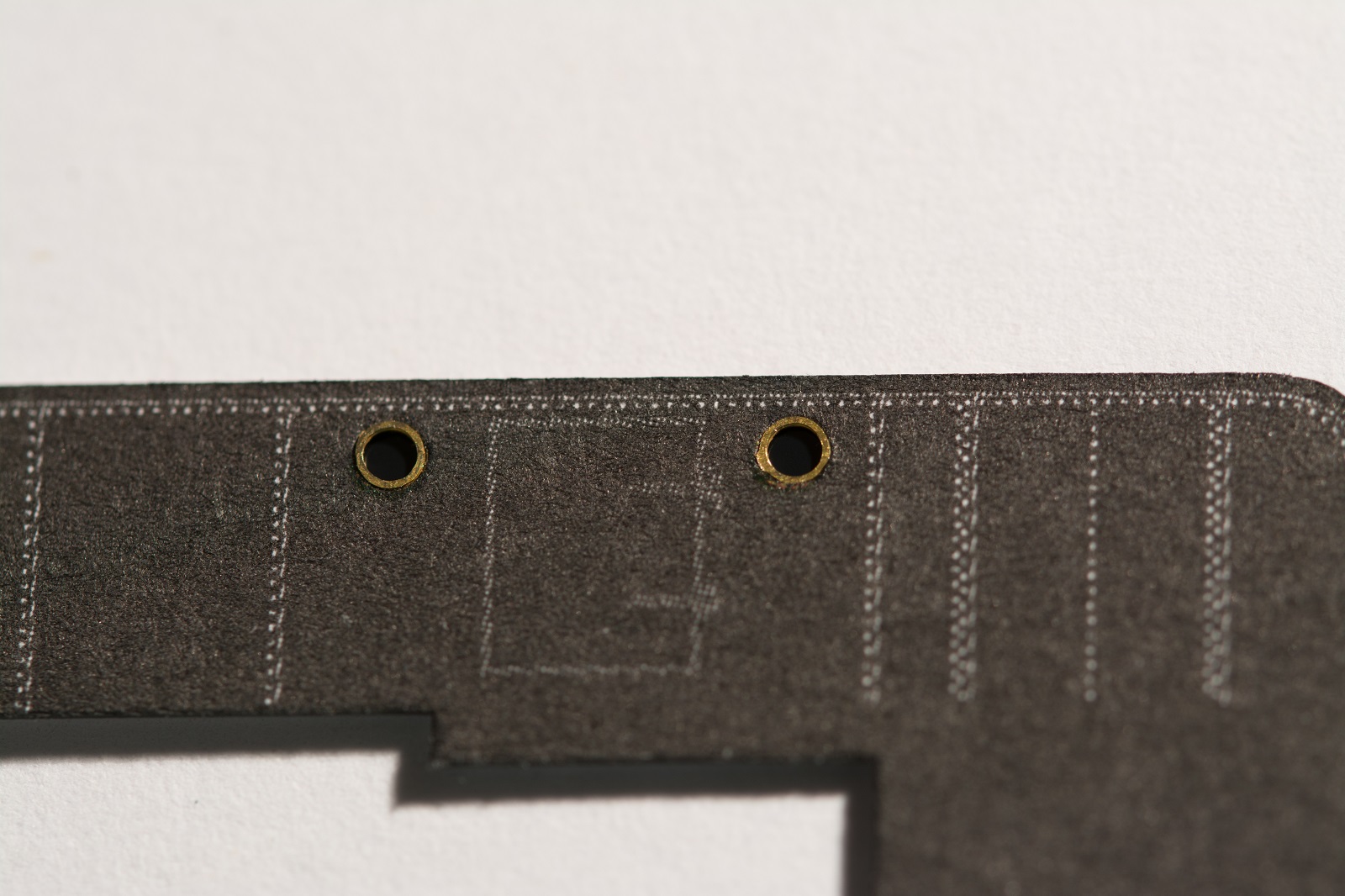
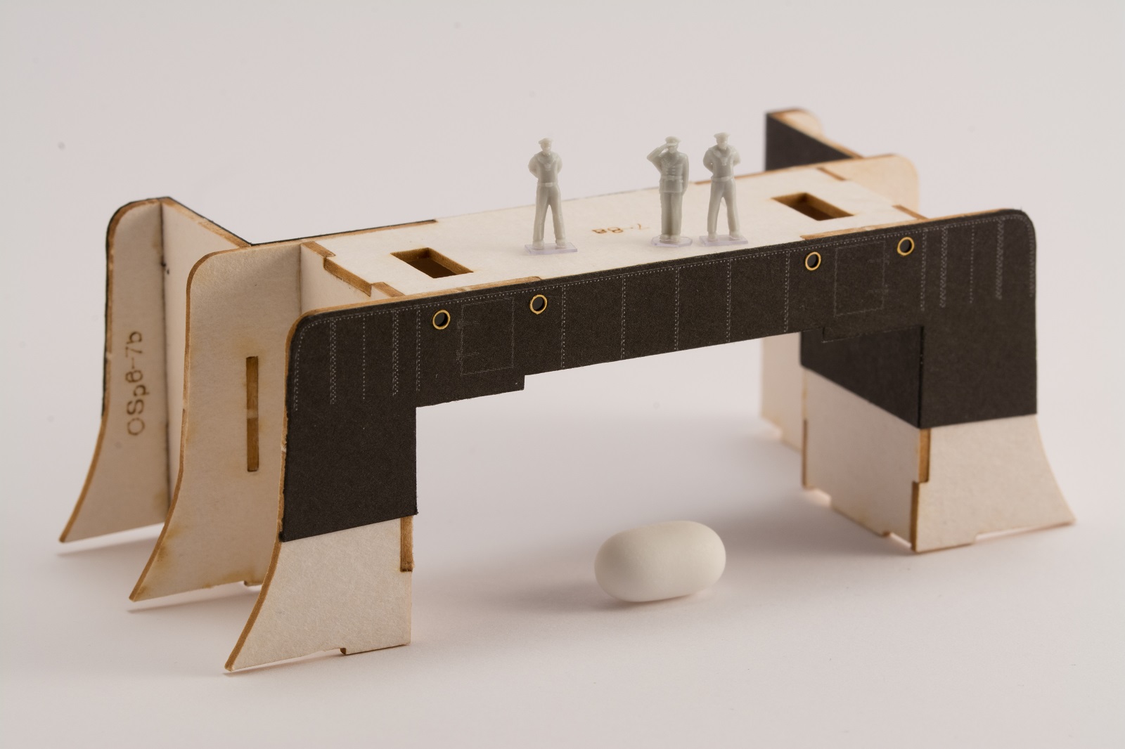
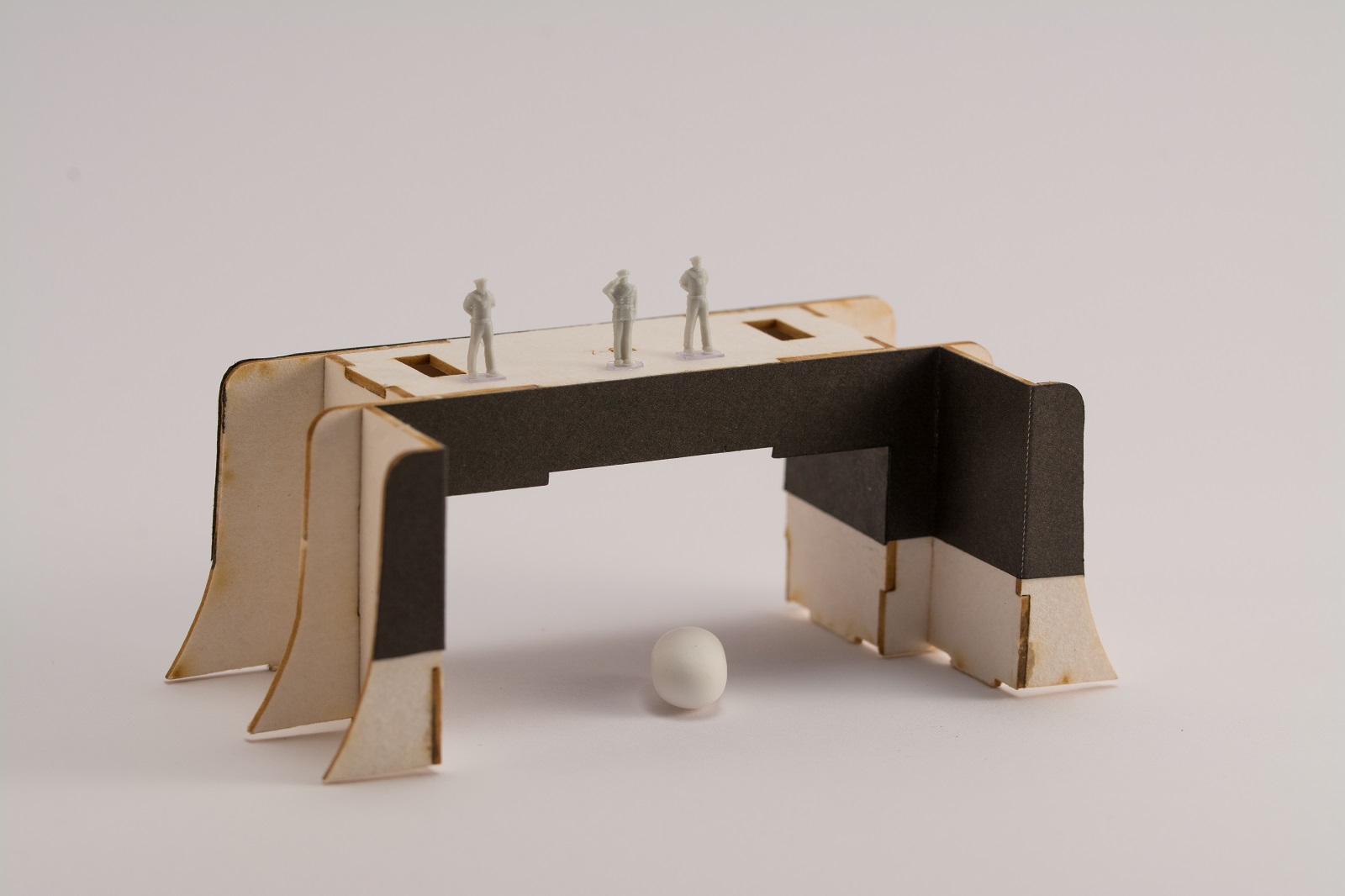
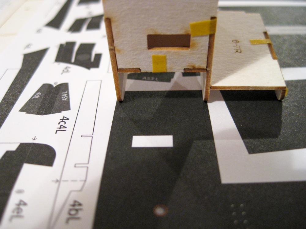
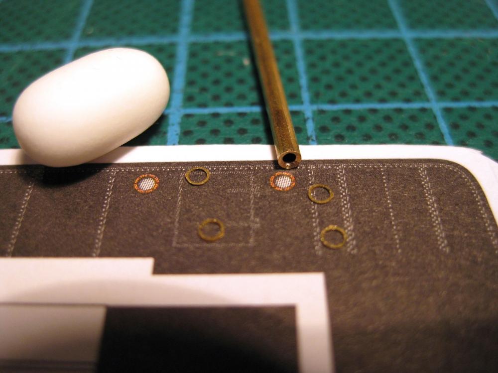
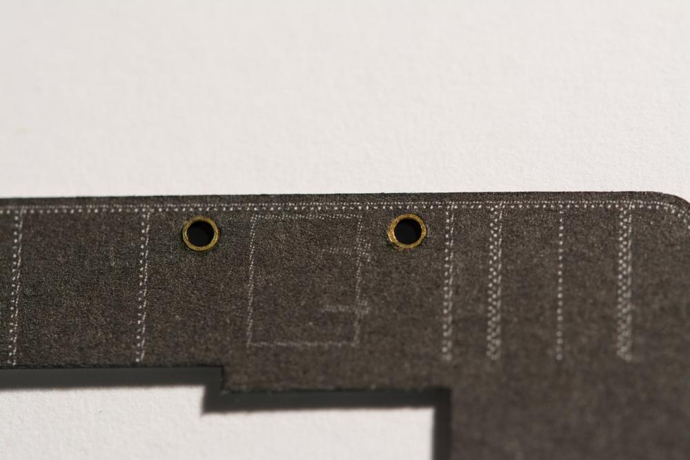
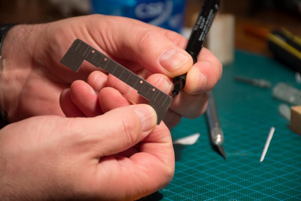
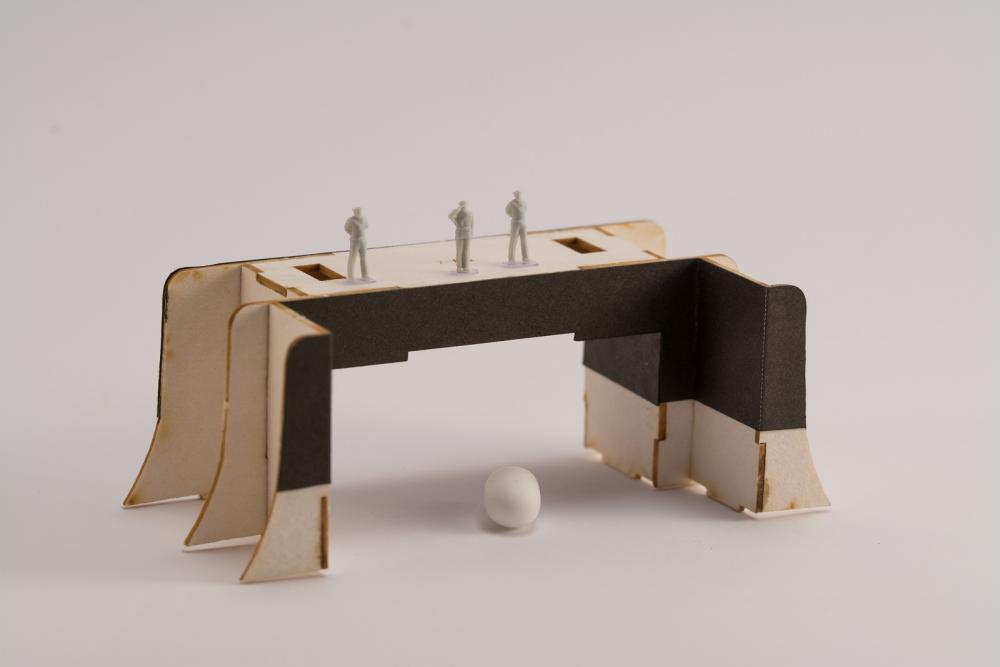
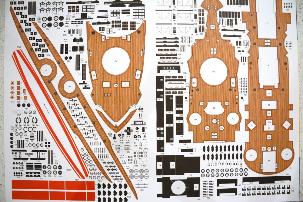
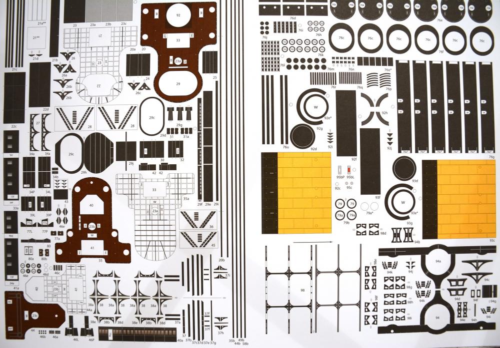
 Hi All and thanks for all the likes and comments. I haven’t got a great to show as I have been pulling down the 3 layers of the hull to reassemble with glue. I have currently done the lower hull and the middle section. I previously mentioned I hadn’t cut out the doublers for the casement guns and so needed to check an update for these. With the kit there was an A4 sheet with changes which I needed to check what they were talking about. Apparently the change is to increase the size of the laser cut holes. The photo shows part of the A4 diagram, the laser cut form with the small laser hole and a former with my trial hole. I thought I better see why the hole was getting enlarged so found the gun pedestal base (part 10) which corresponds with the new hole so mystery solved. I also mentioned the benefit of trial fitting parts before gluing and here is a good example of why. The horizontal forms of the bridging structure had holes in them which were off set to one side and I just randomly put them in for the dry run. Before gluing I checked against the skin which wraps round the structure and low and behold my test fit was wrong. 50/50 chance LOL Card models in general have very little instructions and this one has none so they assume you know what you are doing. There was no indication about the position of the holes in the plans. Check, check and check again is the motto. With the bridging structure now correctly orientated and glued up it was finally time to do some paper modelling, huzzah! The rear skin has some portholes in them which although I quite like the orangey bronzie colour I want to replace all the portholes with photo-etch ones. I already have 1.6mm portholes which were a good fit for these. I used the same technique I described in the Bismarck log where I use a drill to put an outside edge into a piece of brass tube to make a punch, 1.5mm in this case. To glaze the hole in the porthole I wanted to try a technique I came across somewhere, where you use a floppy disk. I think it is mylar, but whatever it is it is dark, shiny and very thin so should look good. I cut a thin strip then cut into little square to fit behind brass portholes. Incidentally the little metal door of the disk is very thin also so went into the spares box in case I can use it for something. Okay new photo-etch portholes installed. Once hole was punched through, I coloured the hole edge black and then put a dab of PVA glue round the edge of the hole and dropped the porthole in and then pressed down with the flat handle of my tweezers to make flush. I then flipped the part over and using PVA again, painted round the area and dropped the plastic ‘window’ over it, again pressing down with the flat of the tweezer handle. The PVA held the port holes and the plastic with no problems despite a fair bit of handling while skinning up the structure. The mylar (?) is thin enough not to be a problem under the paper skin either. I think they look okay and I do like the dark shiny effect of the ‘glazing’ so will continue to use this for the rest of the build. One thing the macro shows up is I didn’t clean up the edge of a photo-etch porthole very well so will remember to take more care for the others…although at 1.6 mm diameter not really noticeable. Just a quick tip for edge colouring. For some of the build at least I will be using Faber Castell PITT artists pens and the black on black works very well. Just remember to come in from the back side (also if using watercolours, paints etc) so if you slip you don’t mark the printed side. Sounds obvious but have done it in the past. Also noticed in the photo another tip. When handling card parts always try and hold the flat part and not the edges. If to small use tweezers or something, it doesn’t take much handling for the edges to become tatty and mashed up. Captain Petr Serebrennikov and a couple of seamen have come to check the progress of his ship LOL (the figures are actually 1:200 1940’s Kreigsmarines I got for the Bismarck). I like the shine of the plastic ‘glass’. The front part of the structure is actually one part so care was needed for the 2 bends on each side to wrap round the wings. You can see the white dotted bend lines. I transferred these to the back side and then with the ruler on the line I scored them gently with the knife just cutting the outer surface and then slide a razor blade under and folded up similar to what you would do with photo etch. PVA glue used for gluing. That’s all that can be done to this structure for now. It needs installing onto the upper deck and the hull skin extends up and over it to complete. Cheers Slog
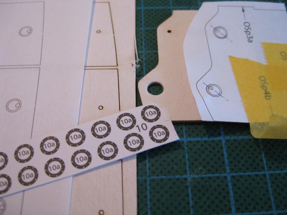


- 244 replies
-
- 18
-

-
- borodino
- dom bumagi
- (and 1 more)
-
oh how I wish I could change a build log title of mine to include the word FINISHED
-
Incredible work Greg and at 1:350 as well ! Got to love photo-etch. Cheers Slog
- 342 replies
-
- 2
-
-
- dreadnought
- zvezda
- (and 2 more)
-
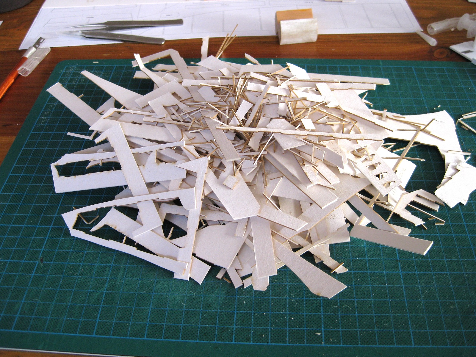
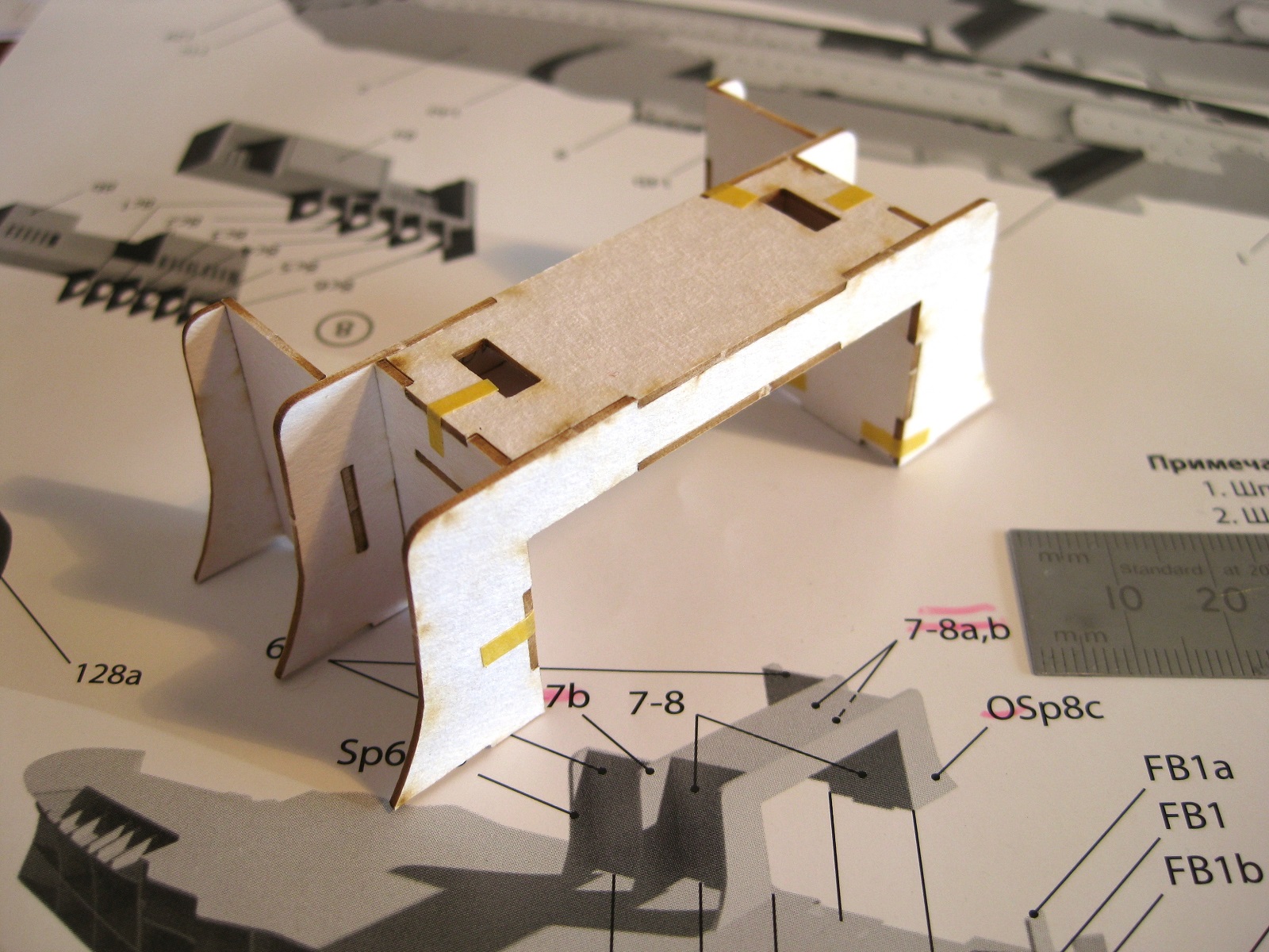
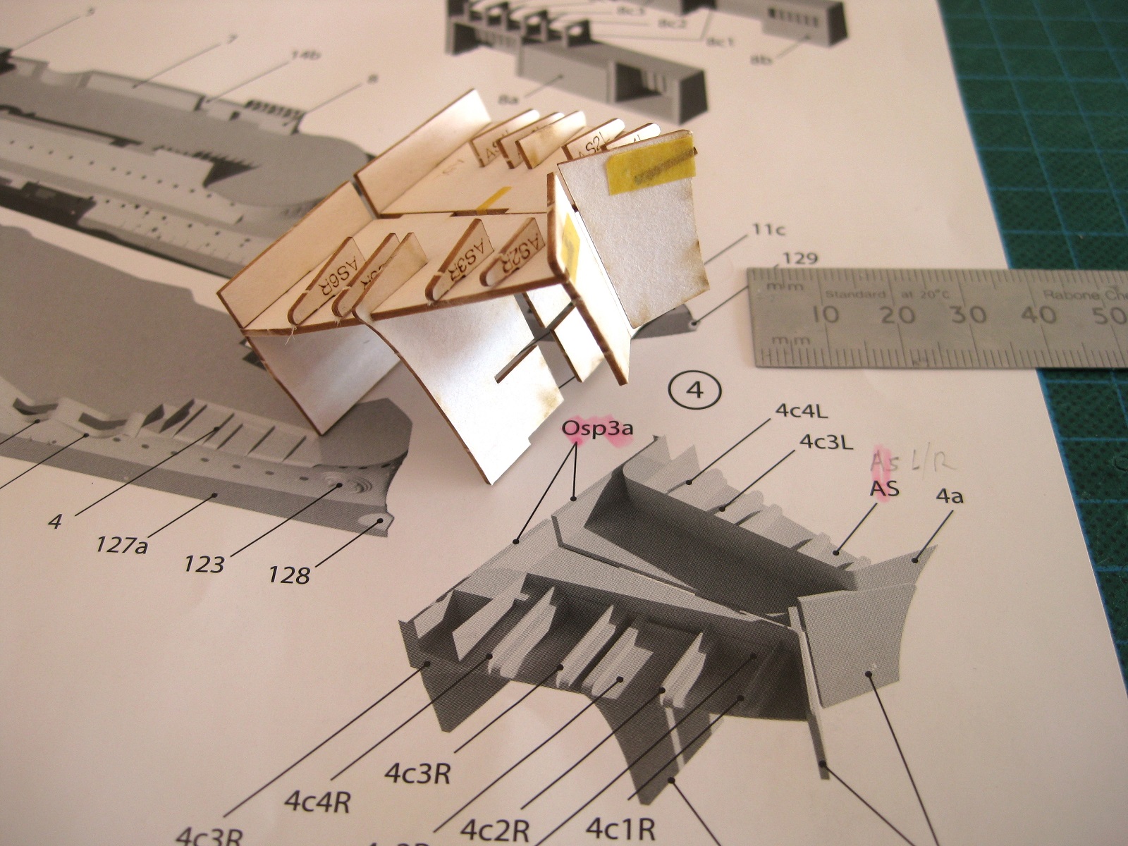
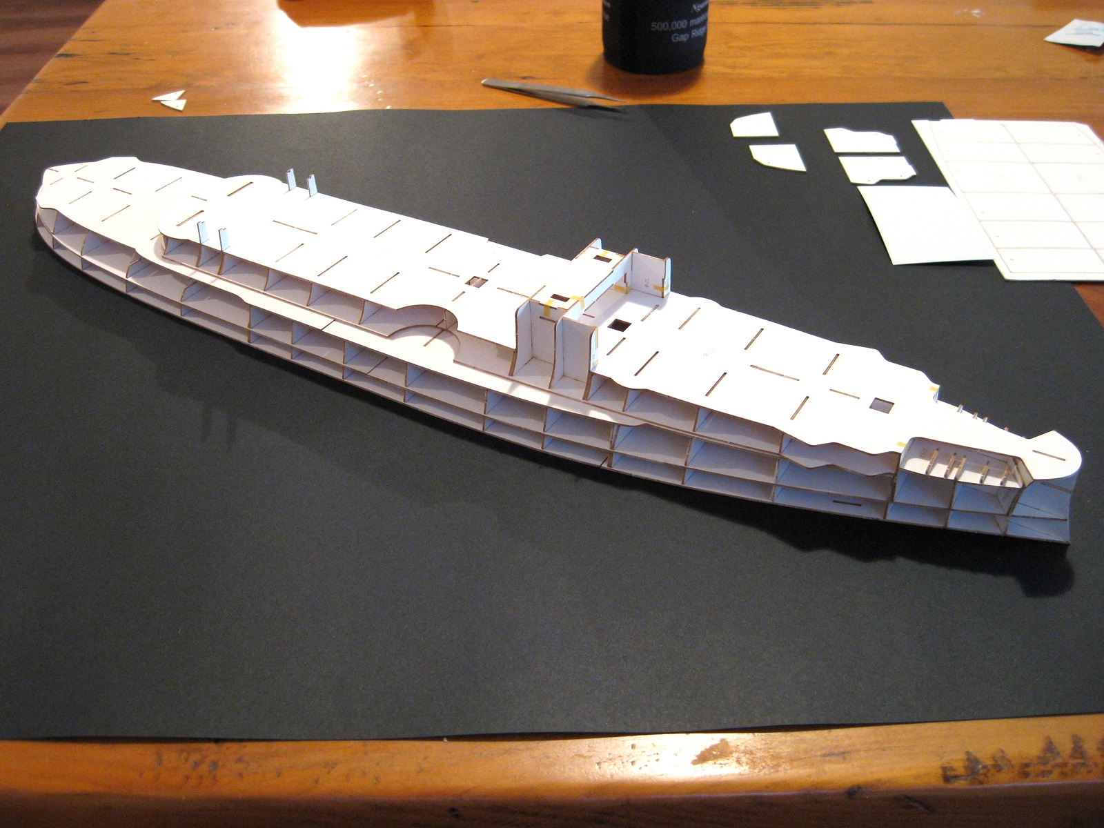
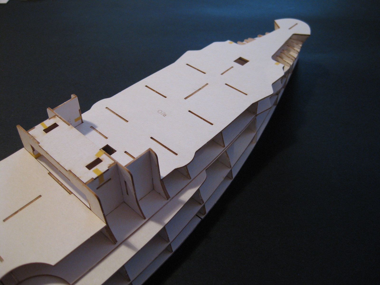
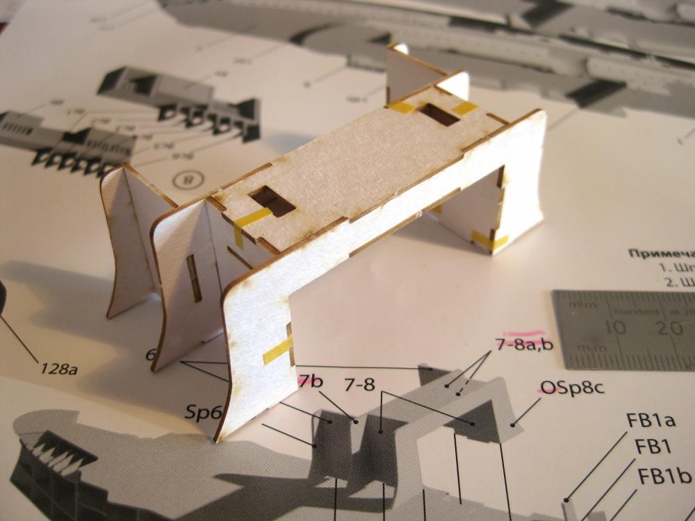
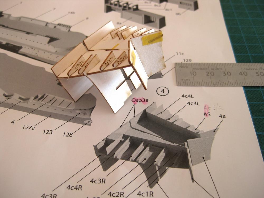
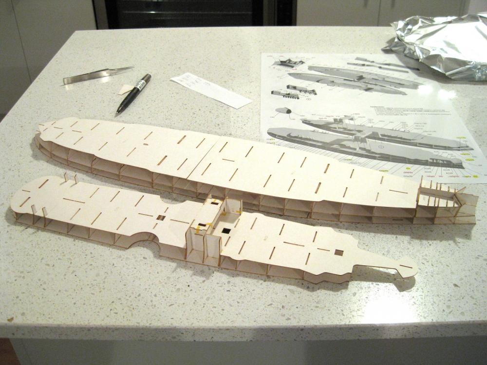
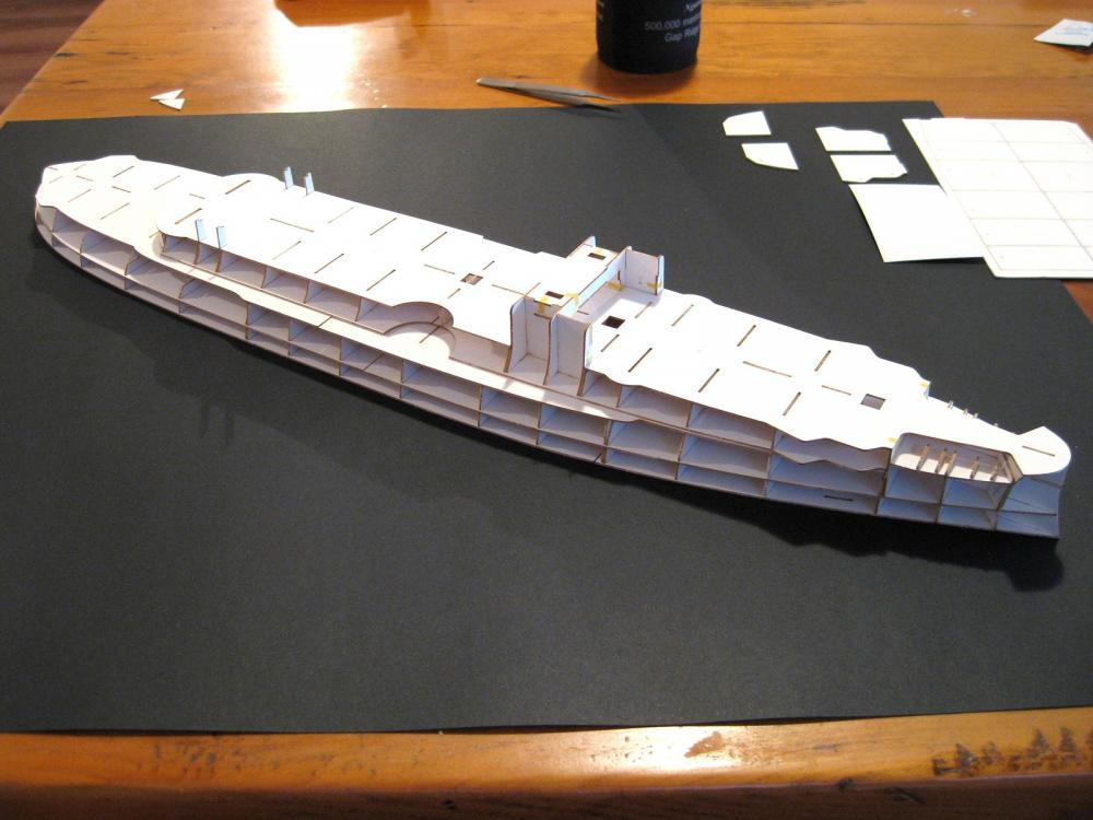
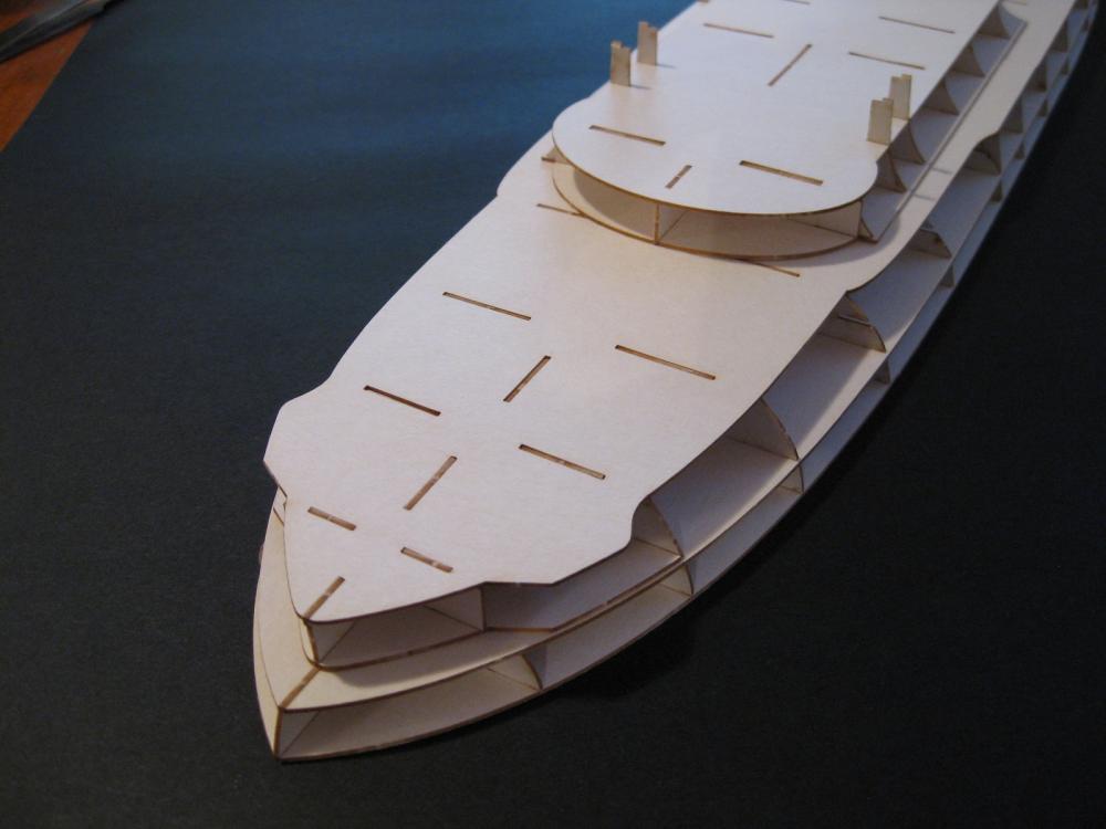
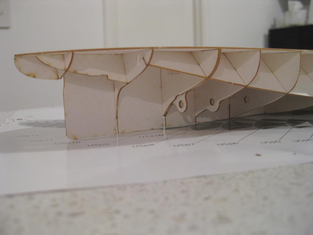
Hi Chris, the tabs are making the build so much easier. The Bismarck had thick formers but no tabs and I had a few alignment issues trying to keep square to the lines. Hi Marv, I say give it a go. I find card modelling very rewarding when you cut, fold, bend, role and glue a bit of paper into a recognisable shape. Although saying that sometimes you ask if they really want you to form a tiny piece of paper into something! More pictures coming up Joe. Okay spent a fair amount of time today making a mess LOL. The picture shows the off cut scraps of around 4 and half sheets worth of laser cut forms. Couple of notes about this; firstly I save any largish scraps and throw them in my scrap card box in case I need to laminate any paper parts for the kit. ( I periodically check the kitchen for suitable packaging and save any that’s suitable. There is soup container packaging which is exactly 0.5mm which I have a lifetimes supply of LOL) Secondly I go through the scrap pile as I am binning it to make sure I am not throwing out any parts which I have missed on the ‘Scrap’. This is the ‘bridging’ structure which goes across the width of the hull and is being trial fitted hence the little strips of Tamiya tape holding it together. I will need to check before permanently fitting to the hull as I think it may need to be skinned/plated with the finished paper parts before final fitting. The anchor shelf (I’ll keep calling it this unless someone knows of another/correct term) gave me lots of grief as I couldn’t find all the parts reference. I searched each laser cut sheet again and again until I realised the other references were to the printed paper part! Again I think this may need skinning before final fitment. Dry fit again hence the tape. Okay most of the upper hull structure cut out and laid out to form the various levels of deck working upwards. The big sheet on the right contains doublers with holes in them for the casement guns and didn’t cut them out as I need the hull put together to determine their position. Okay dry fit of the upper hull. I started working from the lowest part (as per photo 9 above ) and it became apparent that the upper hull is essentially 2 platforms. Surprisingly these are located together only at the front and rear tabs. I am glad I trial fitted the upper hull structure as there were a couple of items which would have caught me out. Firstly there is a horizontal doubler at the rear which I left out and thought at the time it looked strange until I realised it was missing. Also a number of the vertical bulkheads are doubled up also but it isn’t clear in the plans which goes to the front and the back as usually the shapes are slightly different so care will be needed to verify before glue goes anywhere near it. I trial fitted in the anchor shelf, which was very fiddly but would be easier when glued up and also the bridging structure which dropped in nicely. All in all the extra time taken dry fitting is time well spent. The two upper hull halves together and looking pretty good. I love the shape of these ships. Stern shot showing where the balcony? Veranda? will be. This is one of my favourite parts of this ship. The wasted bow for the anchor shelves with the ‘snout’ and the sticking up side structure which is plated flush with the sides. Such interesting shapes these ships had. Next up will be to check any notes about assembly to confirm placement and also to check some of the printed parts relationships before the big glue up to complete the hull. Cheers Slog


- 244 replies
-
- 20
-
-
- borodino
- dom bumagi
- (and 1 more)
-
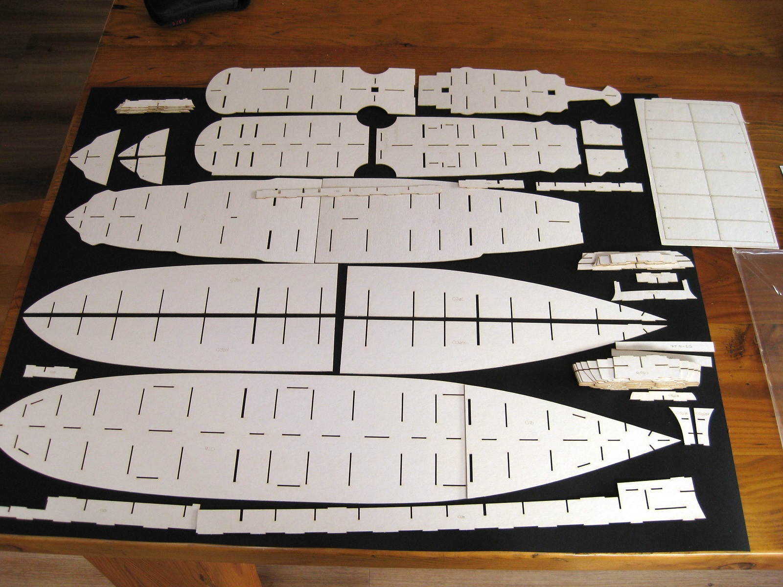
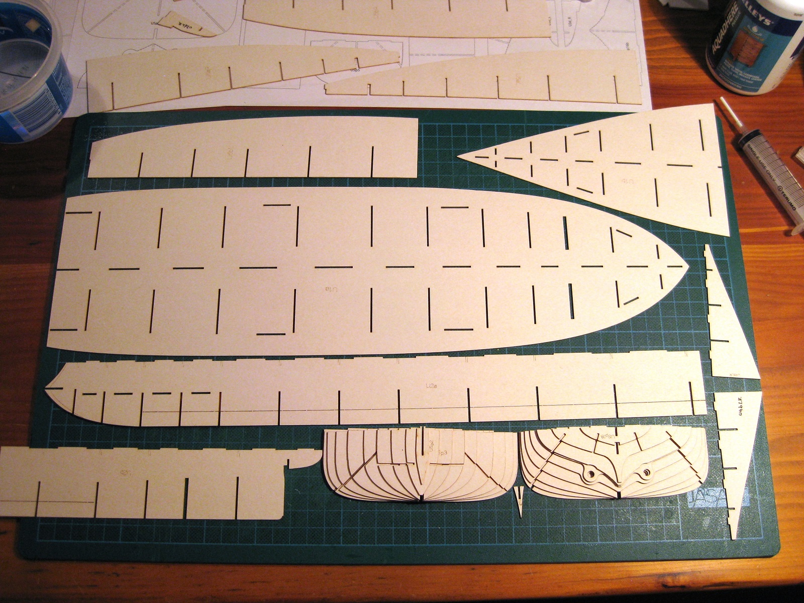
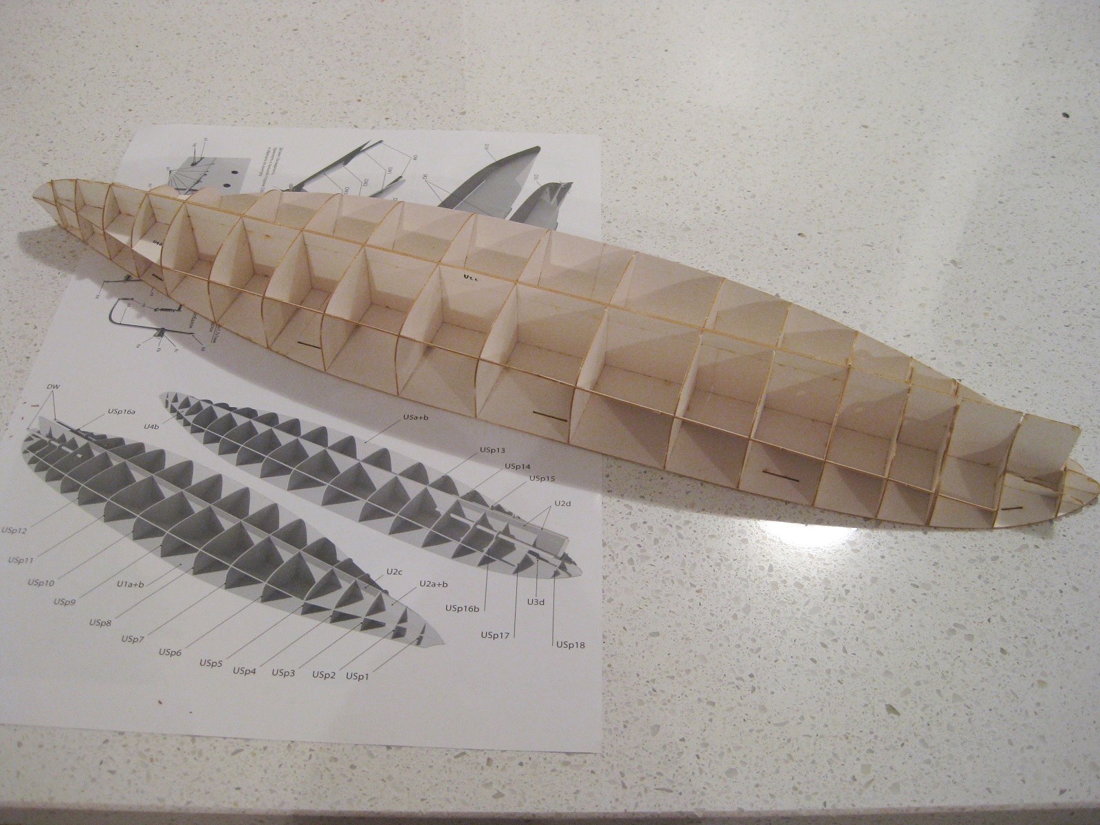
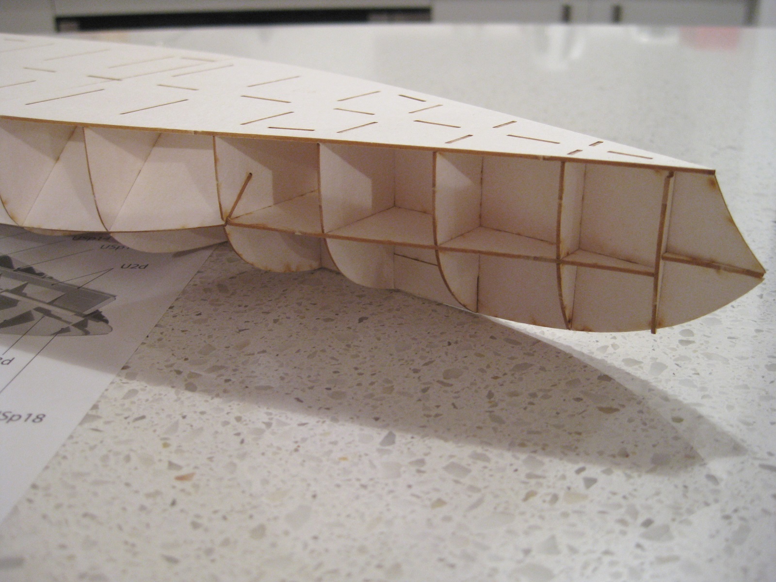
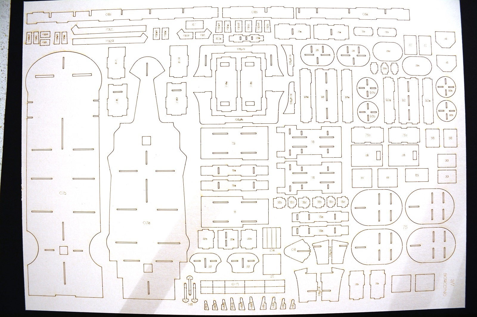
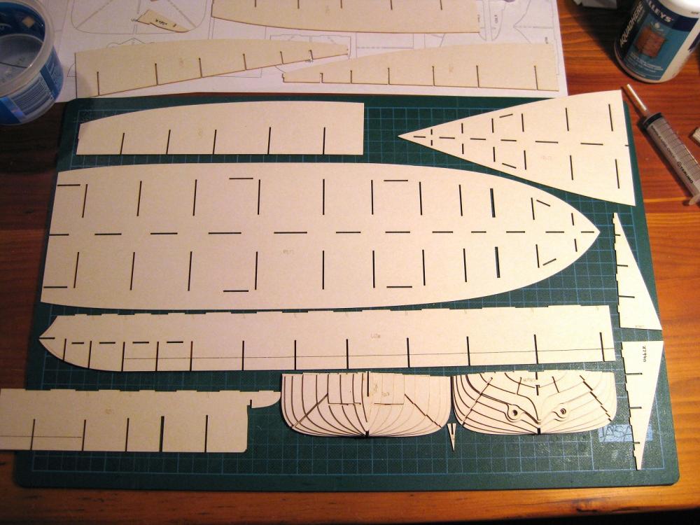
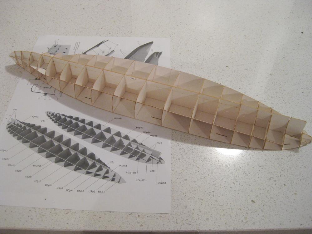
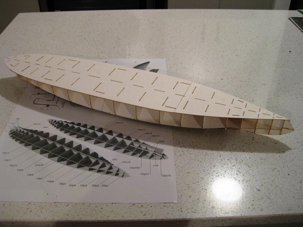
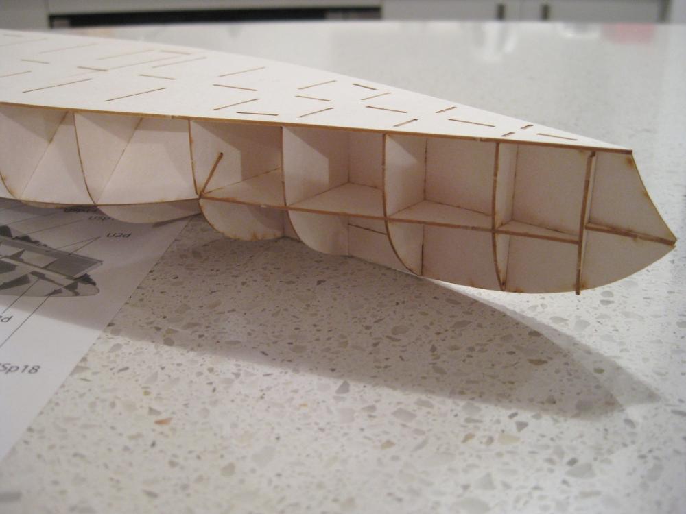
Hi, Finally put knife to card and started with the laser cut hull forms. The hull is made up of 4 major parts; the underwater hull (designated U ), the upper hull (designated O), the front anchor shelf (?) and a bridge like structure which goes across from side to side. There are also 4 other hull structures which on first glance get made off the ship and then get placed on later. I started with the lower under water hull and first impressions of the laser cut forms are very good. There were a few parts where the laser didn’t quite make it through the backside outer layer but this was easily sliced through. Hats off to Dom Bumagi on the design of the hull so far. Each of the transverse bulkheads have tabs to fit through the horizontal parts so each part is self-squaring and self centering and should be a breeze gluing up. (The Bismarck transverse bulkheads didn’t have these additional tabs and it was a race trying to get everything centred and lined up before the glue went off) All the parts cut out and the little nibs removed with a swipe of sandpaper. Dry run of the lower hull which went together perfectly. Everything slotted together easily with no trimming necessary. Next up is to pull it down and then reassemble with glue and then straight on to the upper hull which is more complicated and has a few steps to follow for insertion of the separate anchor shelf and the upper side to side structure. Cheers Slog
- 244 replies
-
- 13
-
-
- borodino
- dom bumagi
- (and 1 more)
-
Looking good Jeff. You are certainly motoring along now after your hiatus. Cheers Slog
-
The wooden deck looks superb. Really moving along. Cheers Slog
- 342 replies
-
- 6
-
-
- dreadnought
- zvezda
- (and 2 more)
-
Thanks to all for your likes and comments I thought you might like this one. I haven't used laser cut detail sets before but wondered how they compare to PE. Thanks for the correction, I guess Google Translator still has a ways to go. I have translated some bits and pieces and on the whole it kind of makes sense with the odd crazy word thrown in now and then. I am sure what should be 'Part' has been translated to 'Children' LOL. Not sure about diorama it takes me long enough to do one or even finish one. Welcome aboard to all. Really itching to get cracking on this one and will get stuck in this weekend. Cheers Slog
- 244 replies
-
- 4
-
-
- borodino
- dom bumagi
- (and 1 more)
-
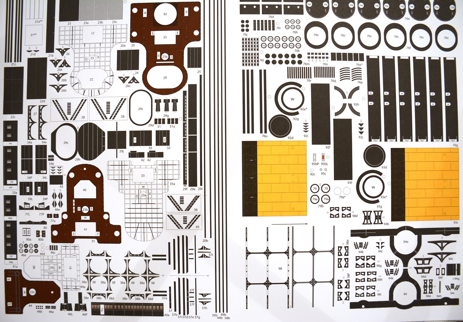
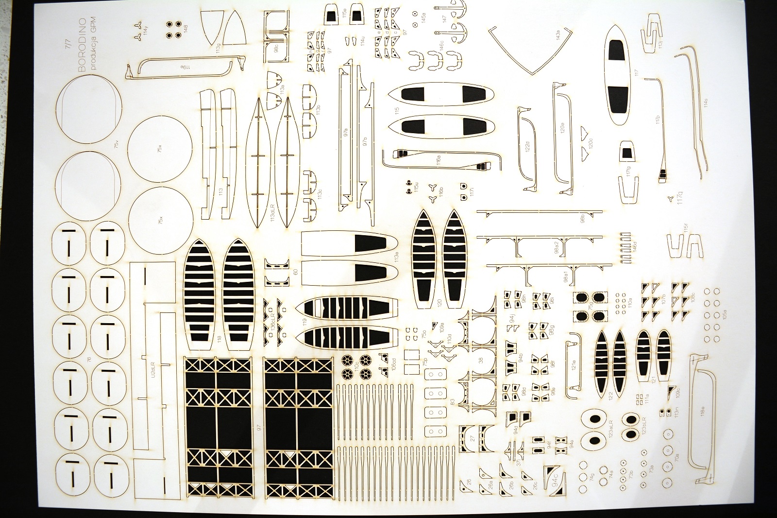
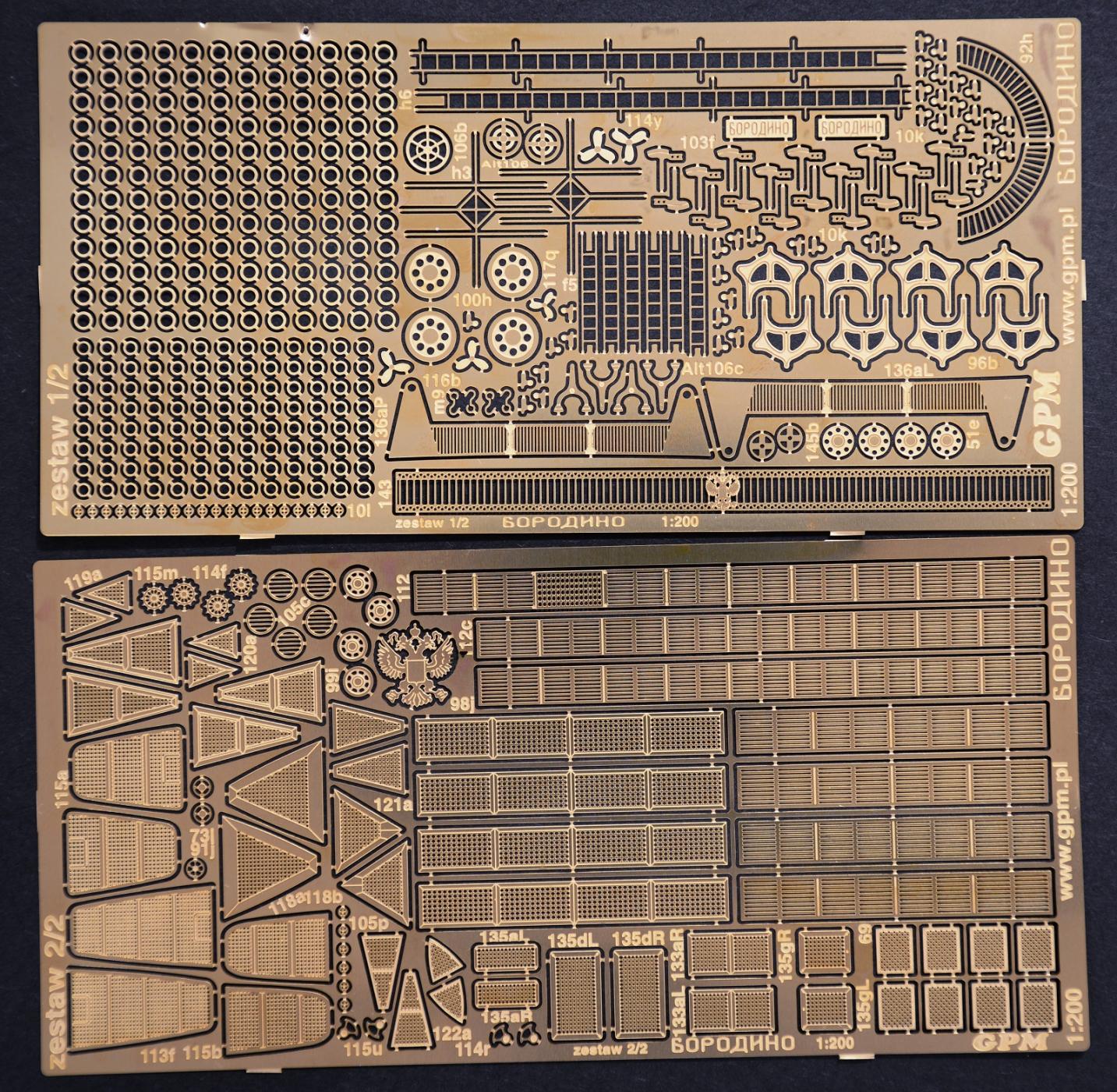
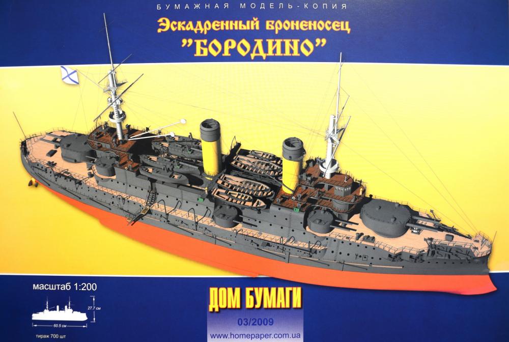
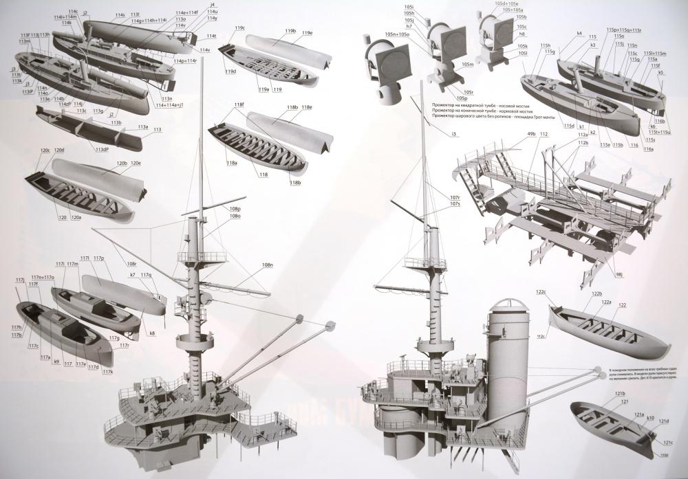
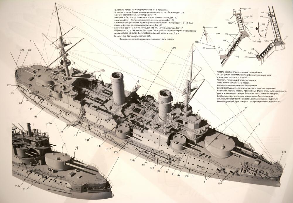
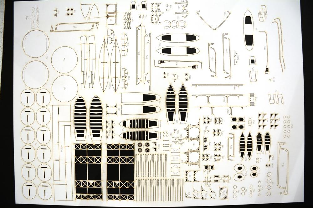
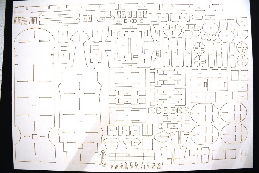
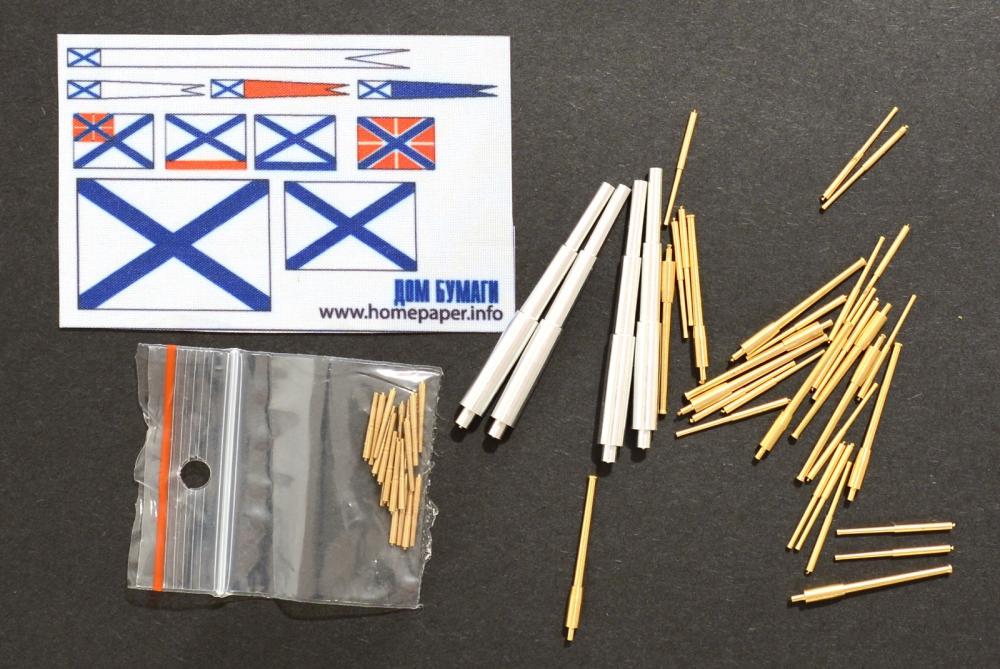
Welcome to the start of my latest build. Finally getting back to working on a ship model after a considerable time although during that time I have been working on and off on the Mazur D-350 card vehicle.. I checked my logs and I last worked on the Bismarck over 18 months ago, which has subsequently gone to a new home and it’s also been over 2 ½ years since I have done anything on the Endeavour which is still waiting patiently. So it’s high time I started another ship project. I poured over a lot of different ships from different publishers and finally settled on the Borodino by publisher Dom Bumagi, which is a Ukrainian company but according to Google Translator dom bumagi translates from Russian to Paper House. I haven’t come across many builds of the Borodino but one in particular looks really nice so that made my mind up. I chose the Borodino for a number of reasons, primarily because I find pre-dreadnaughts very interesting with regards to hull, gun and structure configurations and the Russian vessels are very well catered for by card model publishers. The Borodino was the lead ship of five Borodino class Battleships and the second finished. According to Wikipedia she was laid down on the 23rd May 1900, launched on the 8th September 1901and in service by August 1904. The Borodino was sunk during the Battle of Tsushima against the Japanese on the 27th May 1905. Here is a link to wikipedia for those interested in finding out more about the ship. https://en.wikipedia.org/wiki/Russian_battleship_Borodino There are 2 or 3 other Borodino class card models available that I am aware of. I previously mentioned that Russian ships are well catered as card models and I know of 12 other Russian ships available which were involved in the Battle of Tsushima. A few of which I would like to do as future builds. There are some Japanese ships from the battle available also, the Mikasa being one of note. Another decision maker is the size of the pre-dreadnaught ships which at approximately 600mm long are half the length of WWII battleships so build duration should be proportionately shorter. I also want to get 1 or 2 smaller ships under my belt before tackling the Fuso or similar sized battleship. I ordered the ship kit, laser cut forms, photo-etch detail set and the metal gun barrel set from GPM in Poland (http://gpm.pl/en ) which took 3 1/2 weeks to arrive. This was longer than the usual 2 weeks. The packaging was to GPMs usual high standard being well protected. Price wise card models are relatively cheap compared to other mediums and worked out approximately; Borodino kit book – A$24 Laser cut forms – A$20 Photo-etch detail set – A$24 Metal gun barrel set – A$14 But postage is crippling to Australia coming in around the A$90 mark. Okay let’s get started. This is my 1st experience with the publisher Dom Bumagi so will be interesting to compare them with others. The first major surprise was how the kit is presented. It came in a plastic sleeve and looked like a usual A3 kit book but on opening it the pages are all loose leaf with no binding. This isn’t a problem as I usually separate the binding/staples and cut the pages in half to the individual sheets anyway for convenience and ease of handling/finding parts etc. The front cover is stiff card with the picture on the front and the reverse as usual details the history of the ship and as usual is in the publishers native language but easy enough to convert to English. Also on the reverse of the cover are diagrams for a lot of the ‘ironwork’ such as railings, ladders, stairs etc. The diagrams show the various shapes to scale and the thicknesses of wire required to form them. There are 6 thin pages for the hull skeleton and structure formwork which get glued to thicker card but these won’t be needed due to getting the laser cut forms. There are 6 pages of parts and on close inspection appear to be very well printed on the expected quality and thickness of paper although did expect more parts sheets. The assembly diagrams are on 4 double sided glossy pages and these are very nicely detailed being computer renders as opposed to line drawings some publishers use. Also in the sleeve is a thin strip with more parts on which I think must be an update to replace incorrect parts or additional details. There was also a small thin plastic cloth material with the various flags printed on to it. This is quite translucent and the flag colours are strong on one side but a bit light on the reverse. There are 6 thick A3 sheets of laser cut form parts to replace the kit internal structures, skeleton, ribs etc and 1 thinner sheet for the ships boats, trestles etc. Having used laser cut forms in the past; these are a god send for quickly and accurately building the underlying structures. Previous experience of laser cut forms have been very good, going together perfectly so will see how these compare. Card model ships aren’t as well catered for with regards to additional detail sets like the smaller 1:350 scale plastic kits but typically offer at least a set of laser cut card and/or a photo-etch set. I got the photo-etch detail set as although the same price as the kit book they do sharpen up the model replacing some parts which would otherwise be quite bulky in paper. The set also includes the nice eagle crest for the bow and the stern balcony. There are little numbers next to each part which correspond to the equivalent paper part they replace. The metal gun barrels are a bit of a backup as I intend to at least try to do the larger guns in card as supplied but can fall back to these if that doesn’t work out as planned. The set contains; 4x 305mm (~12”) in aluminium 12x 152mm (~6”) in brass 20x 75mm (~3”) in brass 20x 47mm (~2”) in brass Really looking forward to getting back into ship modelling with this one. Cheers Slog

- 244 replies
-
- 22
-
-
- borodino
- dom bumagi
- (and 1 more)
-
Hi Puckotred, Sorry to hear of your mishap. Its a shame you have put it away as was enjoying the build and it was looking very nice. But I know where you are coming from as doubt I would have the heart to repair major damage either. Its fun putting to together new parts not so much redoing them. Cheers Slog
- 113 replies
-
- 2
-
-
- bohuslän
- nordic class boats
- (and 1 more)
-
Looking great, photo-etch certainly brings life to these models. Cheers Slog
- 342 replies
-
- 5
-
-
- dreadnought
- zvezda
- (and 2 more)
-
Hi Greg, I have seen a similar technique to build up the 'plates' with primer but the tape is removed to create the 'lower' section so when painted overall there are different subtle thicknesses to represent the plates. Cheers Slog
- 342 replies
-
- 4
-
-
- dreadnought
- zvezda
- (and 2 more)
-
That Pontos photo-etch is very nice indeed. Looking at picture 'Hull 4' and trying to visual it on the hull, must only be a couple of mm Cheers Slog
- 342 replies
-
- 4
-
-
- dreadnought
- zvezda
- (and 2 more)
-
Alright, now were talking! Looking forward to this one. Love all the extra detail sets you have got lined up. I came across Flyhawk stuff for the first time yesterday looking for other items and found them to be very expensive compared with say White Ensign etc. Did you find this the case? Cheers Slog
- 342 replies
-
- 5
-
-
- dreadnought
- zvezda
- (and 2 more)
-
I would like to see more expedition type ships like Discovery, Investigator, Fram etc . Also agree with a lot of people suggesting transition ships with sail and steam. Cheers Slog
-
Opinions on Sherline DRO for Lathe
Captain Slog replied to rtropp's topic in Modeling tools and Workshop Equipment
I am guessing Digital Read Out Cheers Slog -
Hi Demetri, Can you tell me your thoughts on Dom Bumagi with regards to paper quality, print quality and how it went together as I am hoping to order a Dom Bumagi kit in the next few weeks which will be my first kit from them. I checked the log in the link and I do like how they use computer renders for the assembly drawings. Cheers Slog
-
Hi Demetri, Thats a nice looking boat. Can you provide other details like scale and publisher? Cheers Slog
-
Seeing it in your hand.. I imagine the handle is bigger than the model! Yeah that last photo took me by surprise also. Makes your work all the more impressive!...unless you are really some kind of giant. Great stuff, well done. Cheers Slog
-
Hi Tim, Another interesting build to follow. Looking forward to see you work your magic on this one. Cheers Slog
- 227 replies
-
- 5
-
-
- BlueJacket Shipcrafters
- Stephen Hopkins
- (and 2 more)
-
Looks fantastic Ron, well done. You'll be able to display this with pride. Cheers Slog
-
Hi Clogger, Sorry I missed your earlier post but you seem to have it under control anyways and looking good so far. As Norman says, care needs to be taken in fairing the bulkheads to avoid sharp turns. I had a similar problem but managed to sand the first planking very thin to get the shape correct and then of course it is covered with the second layer so I dodged a bullet there. Cheers Slog
-
Hi Ken, Not sure if it will help your circle cutting issue but in my last couple of posts in another card modelling forum I did a mini tutorial on using a circle cutter. The wheel rims I cut out were about 22mm outer diameter and about 3mm wide from 0.5mm card. If you are interested in checking it out just click on the link for the Mazur D-350 in my signature. Unfortunately you have to be a member and logged in to see the images full size other wise its just small thumbnails. Can you post what it is you are trying to cut as I have a few techniques I use depending on the size of the part and the card thickness. Small thick laminated parts I take multiple small slices etc. Some times I will file the shape in to sheet brass so I have a hard edge 'ruler' to follow and a few more techniques. I am sure others have methods to share also if you can elaborate what the issue is. Cheers Slog
- 80 replies
-
- 5
-
-
- choctaw
- heinkel models
- (and 1 more)
-
Hi Jim, Looking forward to following this build. You are off to great start. I hope to eventually do a paper version of the Hood by Halinski at some stage. Incidentally the Hood was 262 metres overall length which makes it a gnat's over 1.3m at 1:200. Cheers Slog