
Captain Slog
-
Posts
904 -
Joined
Content Type
Profiles
Forums
Gallery
Events
Everything posted by Captain Slog
-
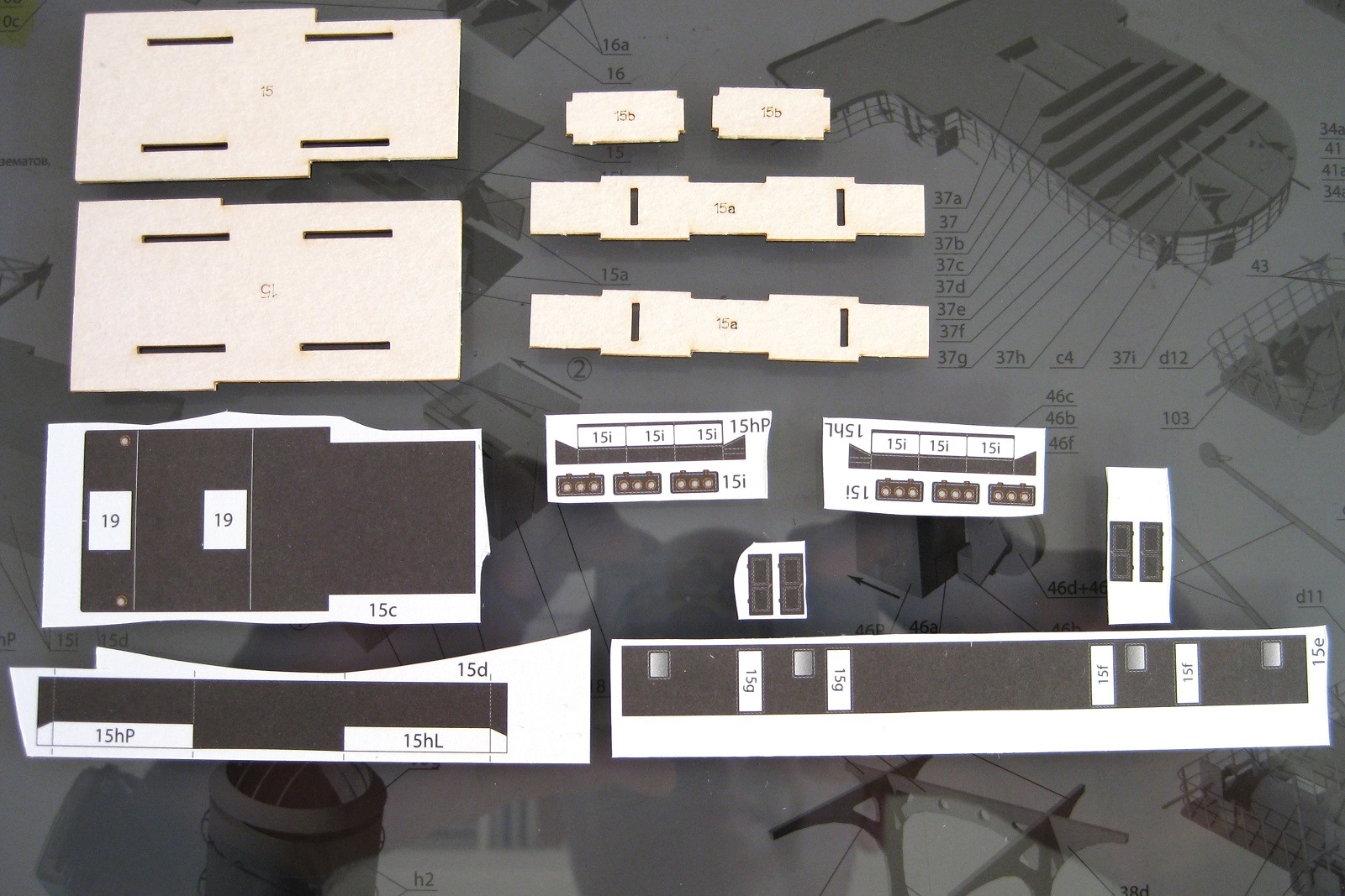
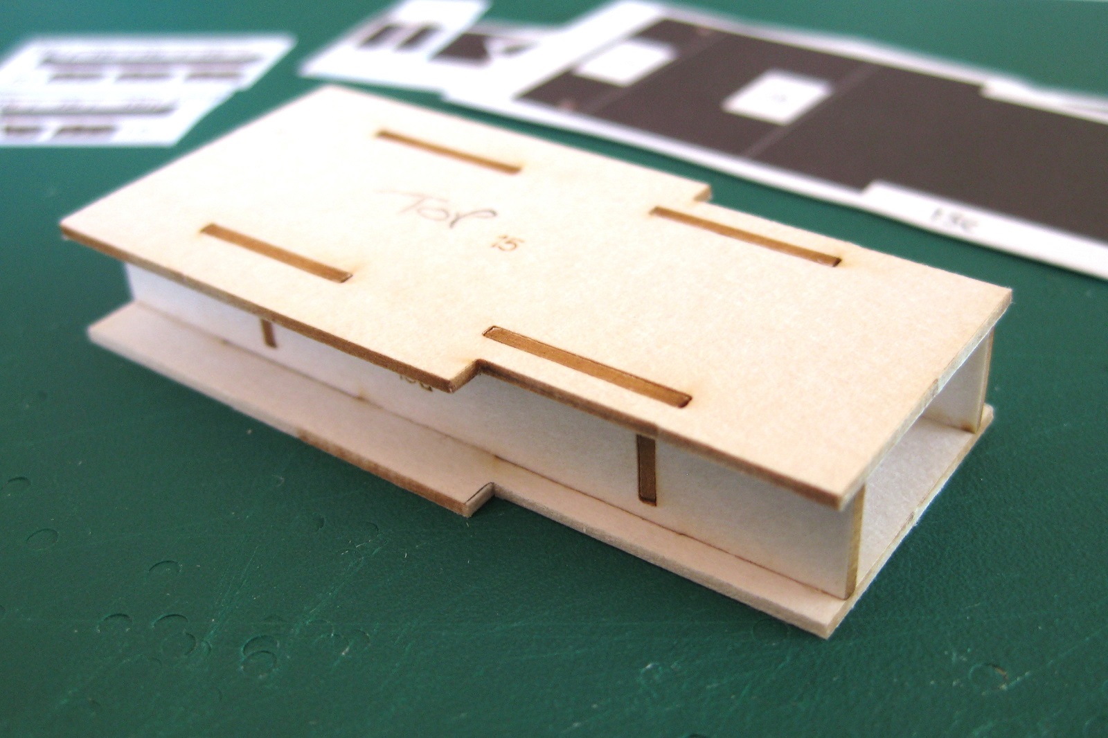
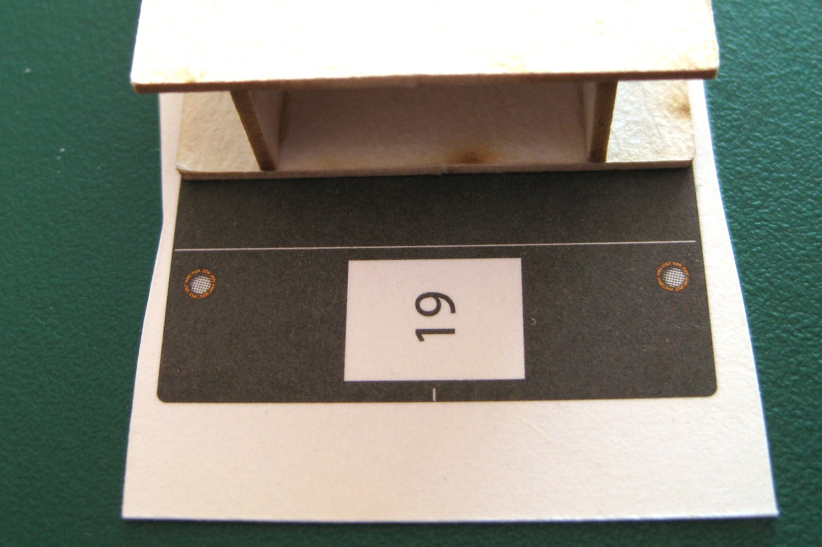
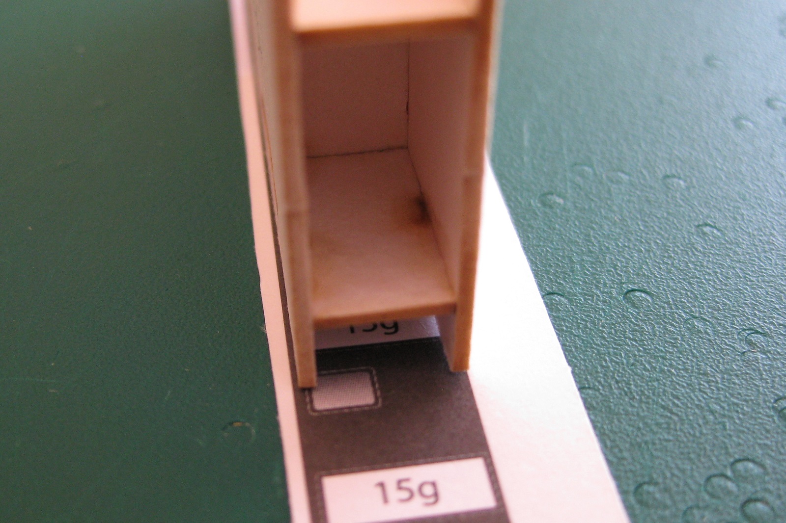
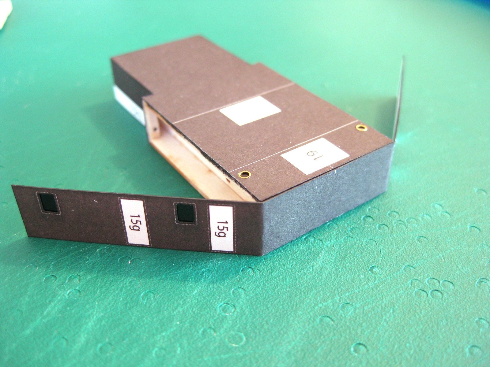
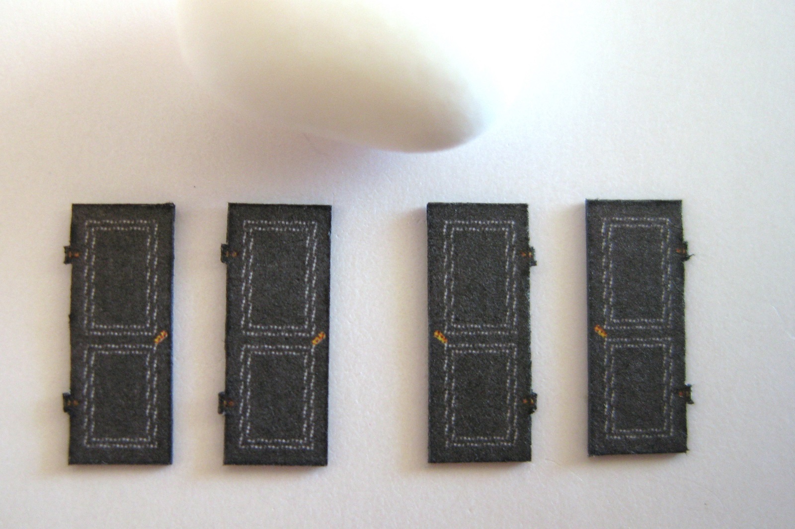
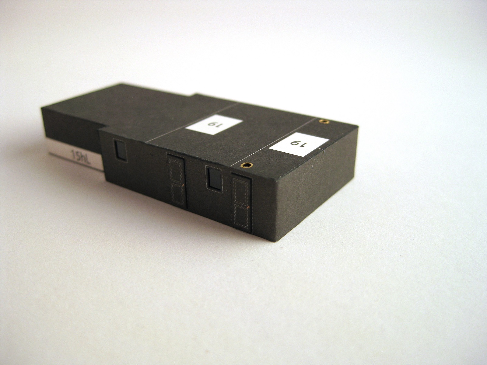
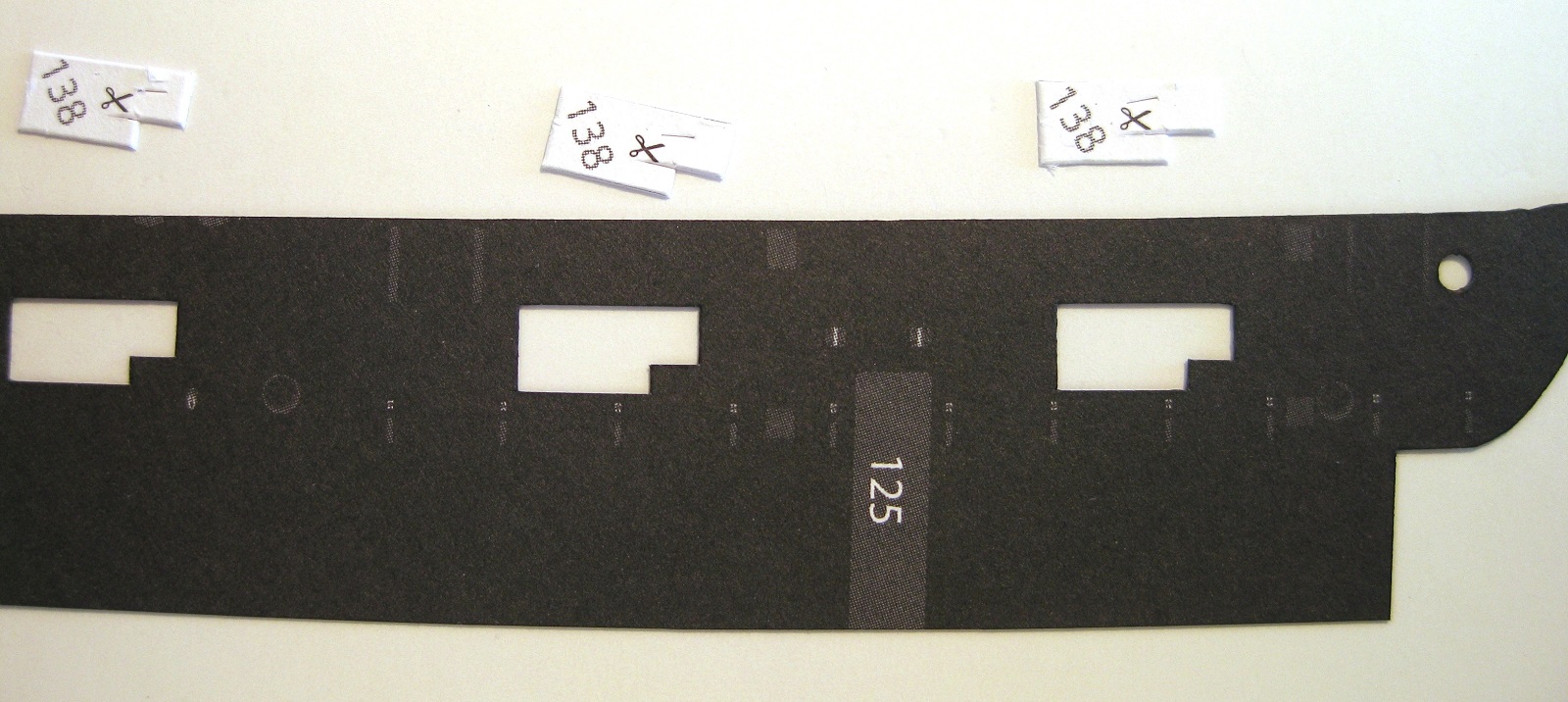
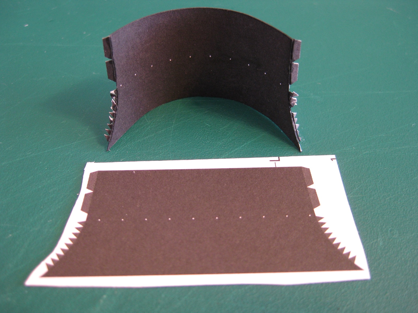
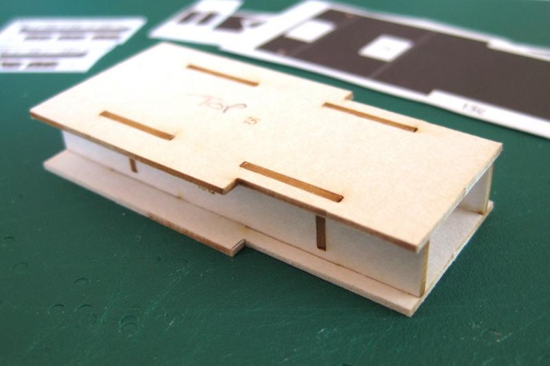
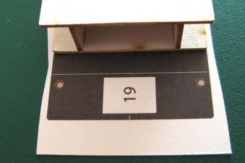
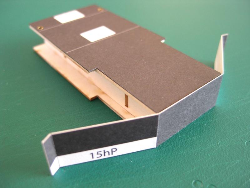
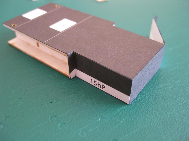
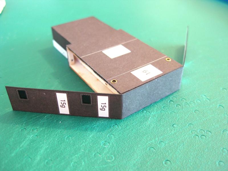
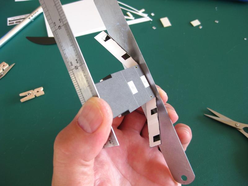
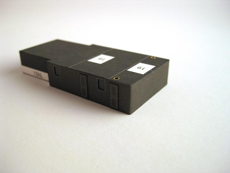
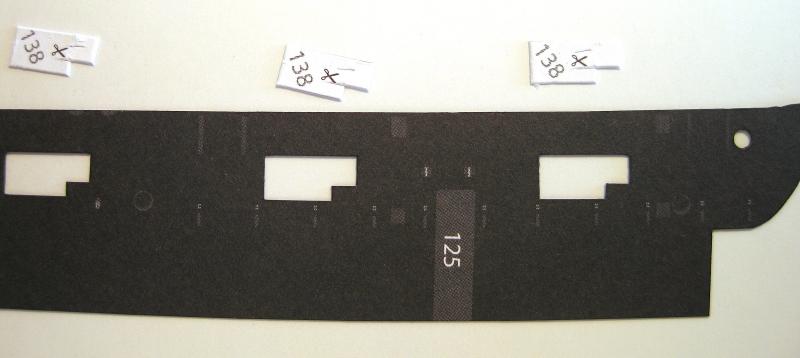
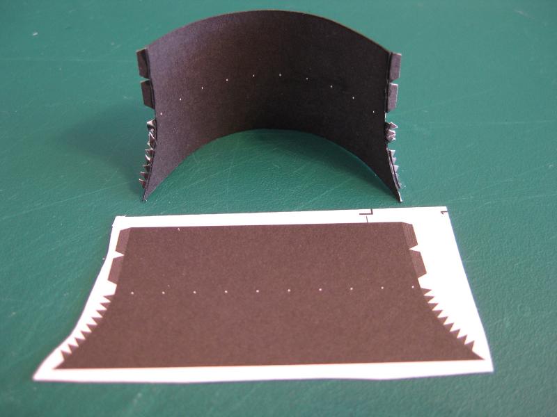
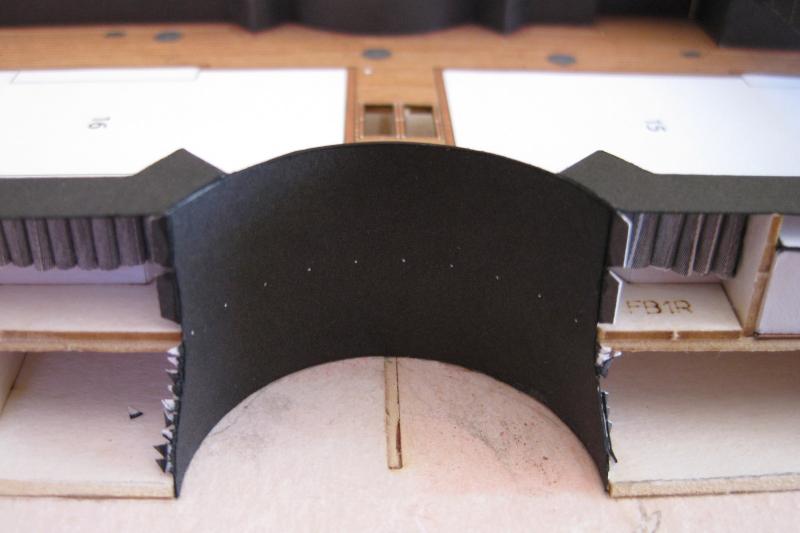
 Hi All, After giving it a bit of thought I decided to do a top side structure for a break from the hull skins and associated works, which go up to parts 14. The next assembly 15 is a cabin type structure located on the centre line and sits partially under the bridge. Here are all the parts laid out ready for trimming and assembly. A few points to raise straight off the bat, particularly with the laser cut forms. The 2 largest forms are Part 15 and are the top and base of the structure and as can be seen they are of a different size and shape. Based on the shape of the side and top skins and the assembly diagram this doesn’t make sense. I double checked the kit template sheet to see if it is just a laser cut form issue but these show the parts being different also. Holding the 2 different forms against the structures final location on deck confirms that the top form in the photo is the correct size and shape and is confirmed by the top skin Part 15c. Thankfully the wrong sized form is large enough to be cut down to match the correct part. Secondly, not an issue but a reiteration of checking before gluing; parts 15a and 15b are the internal structures and although not evident on first glance the slots on each end are in a different positon. I only noticed this when the dry run had it all askew. If I had jumped in and applied glue I could have messed them up. The wrong size bottom form was cut to match the correct top by holding them together and marking the cuts. As can be seen on the bottom form the areas with no laser char were what was trimmed off. After a trial fit again to make sure everything was aligned it was glued together with no issues. I used the Roket glue here but no discernible difference then my usual PVA. Something I have touched on previously but not explained is the relationship and butting against of adjacent skins. Prior to cutting of the skins I wanted to check the relationship of the top and side skins in case I need to take into account any differences when cutting and gluing up. By placing the structure on the top skin, although it doesn’t look it, it is flush with the edge of the form. This means (and I hope!) that the sides are slightly taller than the form to cover the edge of the top skin. Doing the same with the side skin it is, thankfully, taller than the form so should cover the top skin edges. What does this mean and why bother? Well it shows that I can safely cut the parts out to the print lines without concern and also shows that for ease of construction I should place the top skin first (based on the numbering I would have done that first anyway but always best to check). Also I only noticed when the photo was taken that the printed corner and a look at the form confirm that the corners are slightly rounded. (I had to gently sand these on to the form I had to trim down). Incidentally the front of the structure has sharp square corners. This explains why the side skin didn’t have any bending marks for the corners but does have a little white dash to match the one on the photo above to centre the skin for wrapping round both sides. Okay with the top skin on another issue with the forms was found. The rebate has been cut too long as can be seen by the top skin overhanging the edge. This is also a form issue as the skins all match each other. This end skin is bent on the sharp square corners so has been has been pre-scored from the backside with the knife and the bends formed initially and trial fitted to the end of the structure. Once satisfied it fits the front face was glued and then the sides were folded back one side at a time to secure. Because the forms were too short for the small return as mentioned above I cut some scrap card from the laser cut sheet and glued in to support the outside edge of the small return and can just be seen in the photo. Moving to the other end this skin didn’t show bend marks but did have a little centre line for alignment. Remember above, this end of the forms have small radius curves so I held the skin unglued against the ends and then folded the skins back to form the bends. I also cut out the windows and placed some floppy disk glazing from behind and this looks pretty good on larger windows also. Once I was happy with the bends on the ‘window’ skin I glued up the centre section first. I have gripped the part between too rulers to apply pressure to the glued surface. The purpose of the rulers is to spread the pressure because the side skins are only supported on the top and bottom edges by the forms and these is risk of pushing in the middle using fingers only to get a ‘starved cow’ effect. I suffered from this poor bovine look in my early days of card modelling! Doors 15f &g cut out and the close up shows they are handed. The top, bottom and lock side edges were cut out using the usual ruler and knife but for the ‘hinge’ side I used the small ground chisel blade I made for removing windows and square openings as shown away back near the beginning of the log to work round the hinges first and then the straight sides. The basic structure with the doors attached. I like the effect of the doors and glazed windows. Also there are a couple of smaller portholes on the top surface which were replaced with 1.6mm photo-etch using the same method as the hull skins. Next up will be the skylights (15h) that run down each side. Cheers Slog
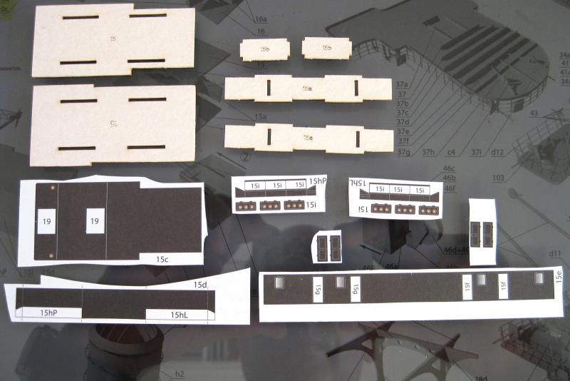


- 244 replies
-
- 10
-

-
- borodino
- dom bumagi
- (and 1 more)
-
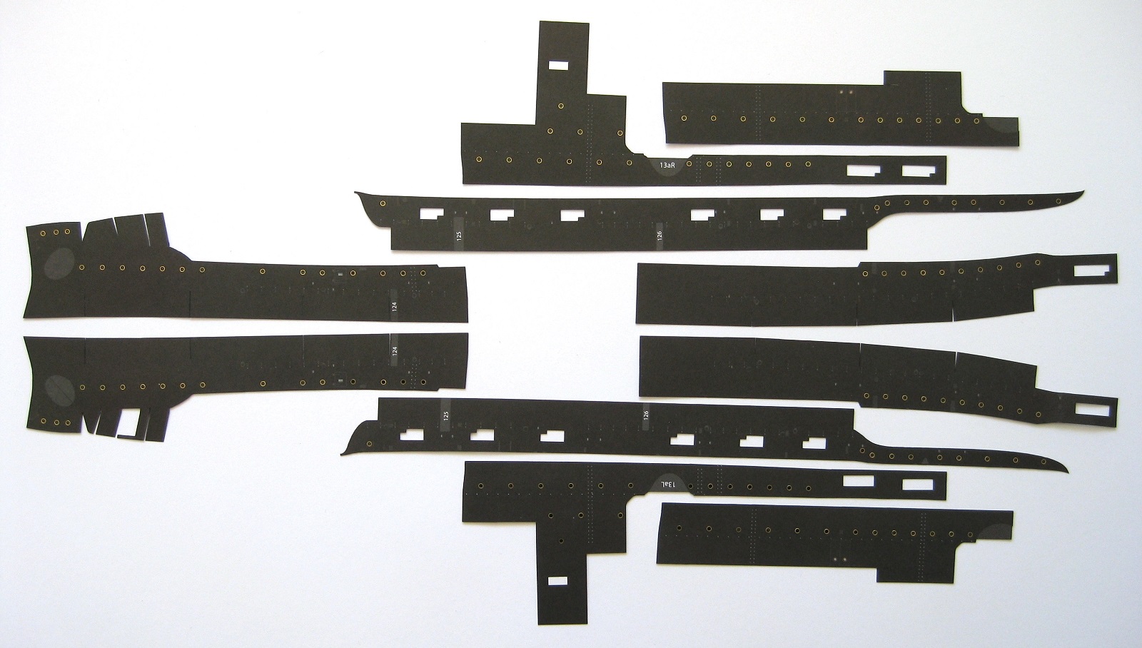
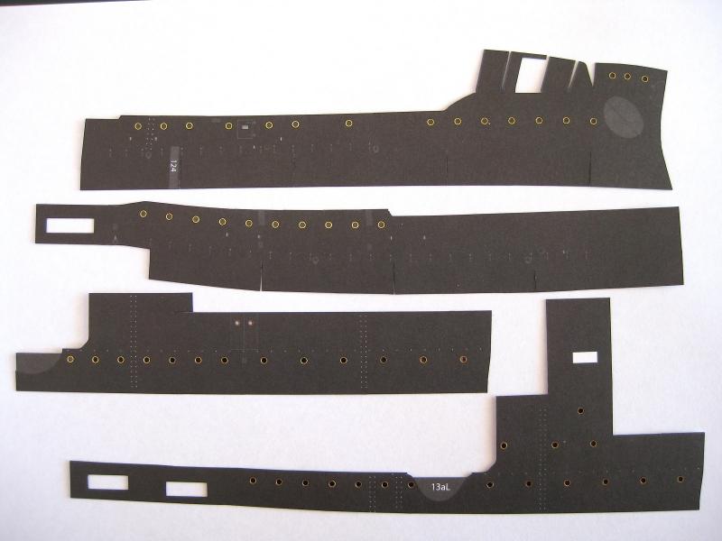
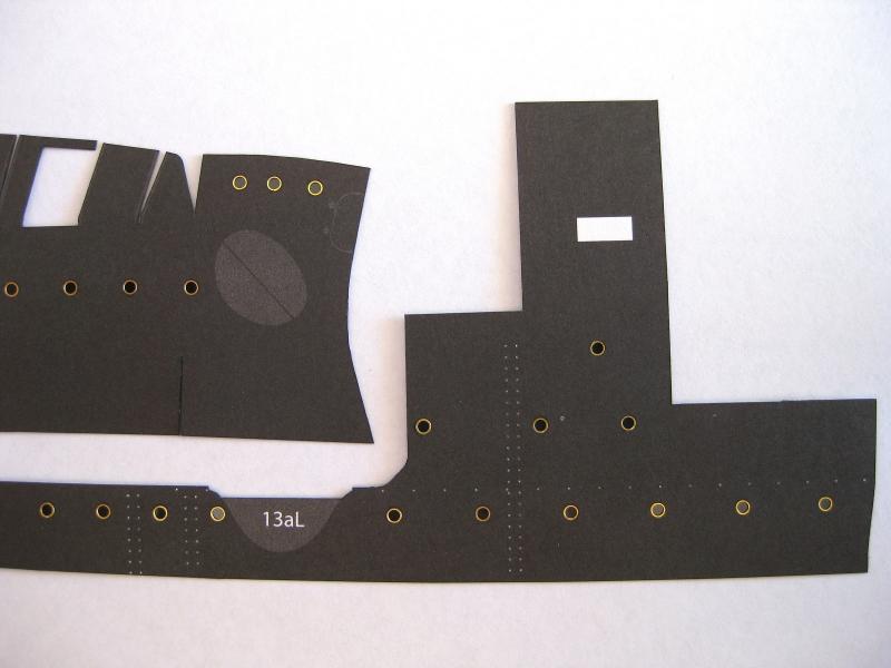
Hi All, Okay here are all the major upper side skins cut out. What isn’t shown is a number of smaller closer panels and stern bulkheads which I will do as I need them Also not shown is a lower belt which I will cover below. Once completed I held some of the skins up to the hull to get a feel for their installation and had an OMG moment as there was no way several of them would fit in their correct locations. I checked the diagrams and they were no help. After a few head scratching moments and playing around with the skins I realised that the kit designer had really put a lot of thought on the construction of this area. Some of the skins need to be pushed under the deck above and the subsequent skins overlap these. This does mean though that the skins will need to be fitted in the order of their part numbers. Once all the skins shown are fitted there is belt that goes right round the bottom of the skins essentially covering up the ‘darts’ removed to allow for contouring to the hull. This overlapping and belting should be more forgiving with the fitment of the panels unlike the lower hull which every skin had to be perfect. Working on these panels was time consuming due to most of the cuts being very gentle curves. Give me straight cuts or big curves any day. I actually enjoyed punching out and fitting all 140+ portholes which was more enjoyable than cutting in this case. The parts shown in the photo above amounts to 12 hours of work. Something I didn’t think too closely on but which is now evident in the photo below is how on earth am I going to manhandle and beat the skins into position with the 3” casemate guns poking through their openings without damaging them?! I will need to think on this more and check to see if it’s possible to squeeze the completed gun assembly through the opening. Now that the bow skin is cut to shape I am now able to finalise the position of the anchor shelf vertical ribs as if you remember there was a bit of a discrepancy in the diagram so I might do this next. To be honest I am a bit nervous of attaching these skins and I think I might hold off and continue on to the next structure as per the part numbering for a bit of an enjoyable break. Will see how it goes. Cheers Slog

- 244 replies
-
- 9
-
-
- borodino
- dom bumagi
- (and 1 more)
-
Looking good Greg, all the photo etch appears to be a considerable amount of work. Don't know how you keep track of it all. Cheers Slog
-
Hi Chris, I haven't yet but the quantities have been tiny, gluing the photo-etch portholes to the skins and the mylar 'windows' to the backs. The biggest part and hence most glue used in one hit would be on the hull skins glued on in post #110 above, The glue was brushed on around the perimeter in stages gluing the part to the card frame and along the top edge which is paper to paper with no issues. The top horizontal section of the existing structure was edge glued to the top of the skin again with no issues. I will say that it definitely grips quicker than the PVA I used in the past. The bond to the mylar was surprising quick and strong; after a light brushed on coating of glue around the port hole and a quick press down on the mylar with the flat of the tweezer handle I doubt I would have gotten it back off without destroying the paper. The interesting test will be on gluing large skins to forms such as decks etc. I will definitely report on its performance as I progress. Cheers Slog
- 244 replies
-
- 3
-
-
- borodino
- dom bumagi
- (and 1 more)
-
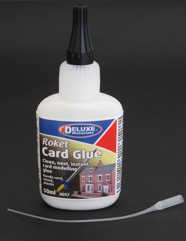
Thanks to everyone for all the likes and comments. Hi DR I wouldn’t have a clue what ink was used. Since this is a retail kit then I am assume some kind of commercial printing was used. I have never bothered downloading e-kits for printing at home as I would never be able to print to the quality and on decent paper that the commercial kits are done to; not without a major printer upgrade anyway. But sourcing decent Bristol would then be the next issue. Thanks Steve hope you have a great Christmas also. Since I am still working on the upper skins (each one takes a little over an hour to do) I don’t have anything new to show but thought I would discuss a glue I came across. As anyone who follows my log knows I am on a constant search to try new, to me, glues. It is Roket Card Glue by Deluxe Materials, a UK company who produce many types of glues and compounds for modellers. I am not sure where I first saw this glue but sourced a few Australian stockists and decided to give it a try. The glue is similar to PVA glue but is very thin like skimmed milk. I have done a few bits and pieces with it and am impressed with its performance so far. I have attached a link to their YouTube video and can vouch that it will stick to metal. I used it to glue the end of a 1mm strip of paper to 0.5mm brass wire and the bond held whilst I bent the paper round the wire. In fact in some cases the paper delaminated but the bond held. The thinness of it isn’t a problem for me as I dispense a small drop and then use a No.0 or smaller paint brush to apply to the part anyway. I do the same with the woodworkers PVA glue but being a lot thicker this usually sits on the brush and then sits on the paper edge surface. The thinner Roket glue gets sucked up in to the brush fibres and then coats only the edge of the paper it touches so definitely a lot cleaner joints can be made. So far I have used it so fix the hull skin a couple of posts back as well as to glue in the photo etch portholes and the mylar panels behind them with no issues. Cons? Well the price is the only one as it is pretty expensive being around A$18 to A$20 for only 50ml considering my usual big brand wood workers PVA I usually use is ~A$7 for 250ml. Saying that, as I only dispense a drop at a time a little goes a long way. It definitely fits in the less is more class Despite the cost, for the moment at least this has replaced my favoured PVA. I will keep you up to date of any additional benefits or issues with it as I use it more. If you are still trying to find a glue to suit you then I suggest giving it a try. Cheers Slog
- 244 replies
-
- 6
-
-
- borodino
- dom bumagi
- (and 1 more)
-
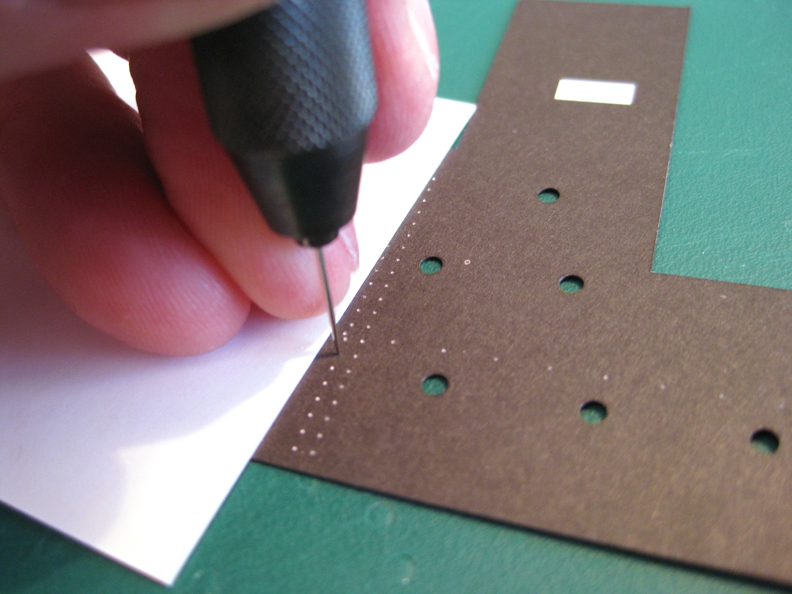
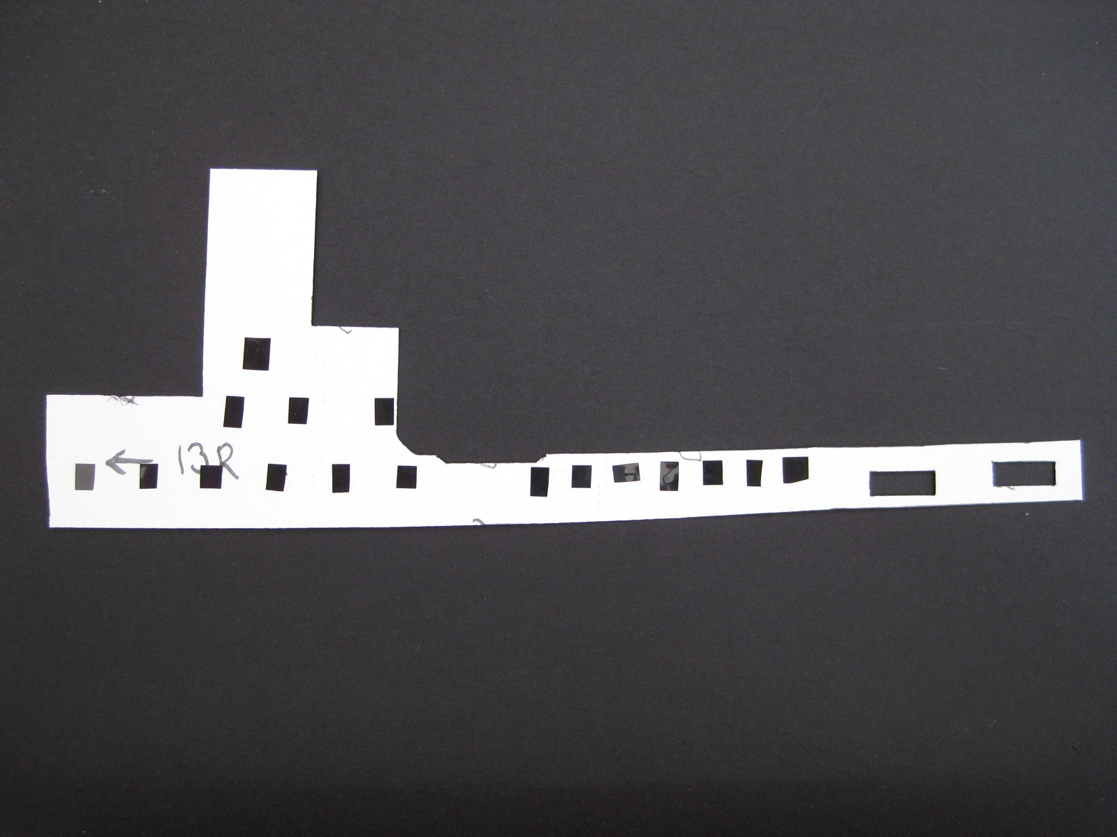
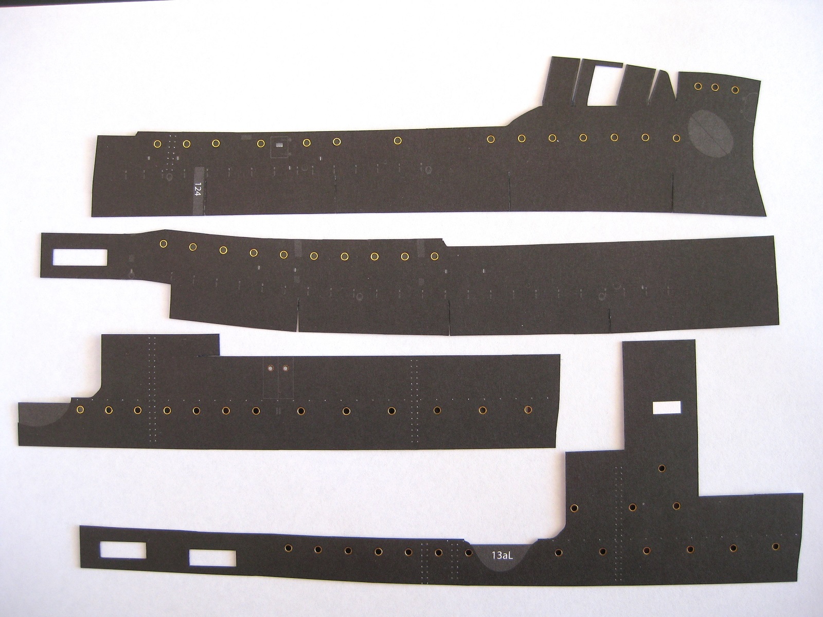
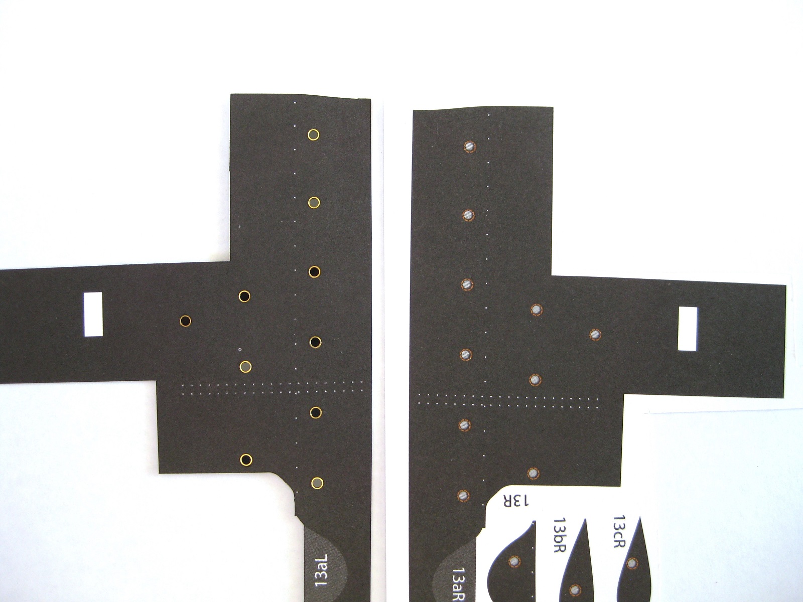
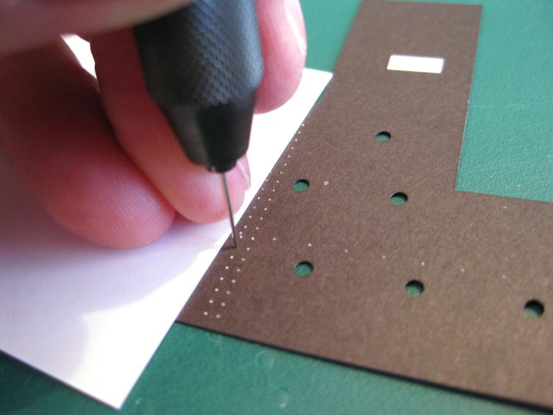
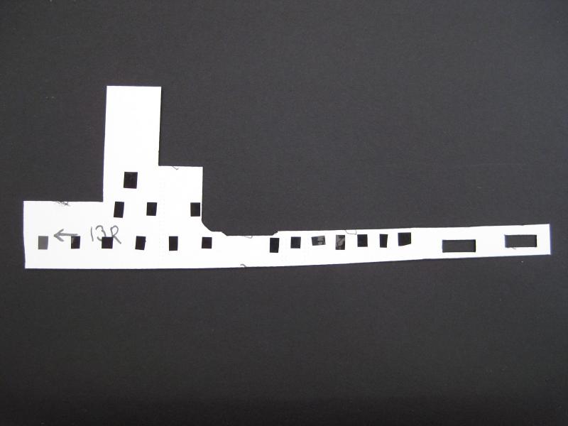
Thanks guys for the nice comments and all the likes, really appreciated. If I want to build the ship more or less in the order of the part numbers, then my procrastination has come to an end and it’s time to continue with the upper hull skins. Not a favourite area based on my lower hull experiences. First up is to finish lining the 6” gun turret alcoves. These were pretty straight forward although the first instance of tabs has been used. Not a fan of tabs but these are needed to catch the edges of the longitudinal hull skins. I partially cut through the tab line and of course the top printed areas of the little triangles started coming away; these were then folded back on the score line. The white dots as explained previously are for the hand rail location and I will cover them further down. The finished part was then progressively rolled round a smooth knife handle until roughly curved to shape. Surprisingly the 2 parts are handed. A finished lining glued in place. The vertical edges look a bit wavy but should line up straight once the side skins are in place and the edges can be joined. I started on the starboard upper hull skins and will replace the printed portholes with 2mm photo-etch ones as discussed in a previous post. The photo shows some of the printed portholes punched out using the sharpened 2mm brass tube method described away back at the beginning of the log. The holes were then coloured from behind using a PITT artist pen. As mentioned each white dot is a location of a hand rail or step iron to be made up from 0.2mm brass wire. I first went through each and every dot giving it a prick with the smallest sharpest needle I had for future installation of the 0.2mm wire. Going over every dot was not as tedious as it sounds and when you see the amount of dots in following photos it was done surprising quick. Also shown a is business card I use under my hand to protect the printed surface as I found when doing activities such as this or cutting etc the corner of my middle finger nail can cause little dents in the paper (even though I bite them back to nothing!). It also protects the paper from moisture from your hand (not that I have sweaty hands or anything LOL). Once all the portholes are punched out and coloured I used a paint brush to apply glue round the hole from the rear of part to prevent getting glue on the surface and pressed the 2mm brass porthole in to place from the front. The photo below shows the rear of the part with the floppy disc glazing glued behind each porthole. The starboard skins done to date; cut out, edge coloured with the portholes installed and glazed. There are still several more skins to do for the starboard side. Also some of the glazing looks black and some look grey; they are all black it’s just reflections depending on the angle of the camera. The cutting out the skins was very time consuming as there is not a single straight line cut along any of the major edges, they all have some degree of curving to take into account the shape of the hull. Similarly some of the straight runs of portholes look slightly off but again once attached to the hull they should line up parallel with the decks. Just a close up. Here is a comparison shot between the original printed portholes and the reworked brass ones. I think replacing them is worth the extra effort. The reflections on some of the glazing spoil the effect a bit. The plan now is to get the rest of the starboard and all the port skins to the same stage before the big glue up. Cheers Slog

- 244 replies
-
- 14
-
-
- borodino
- dom bumagi
- (and 1 more)
-
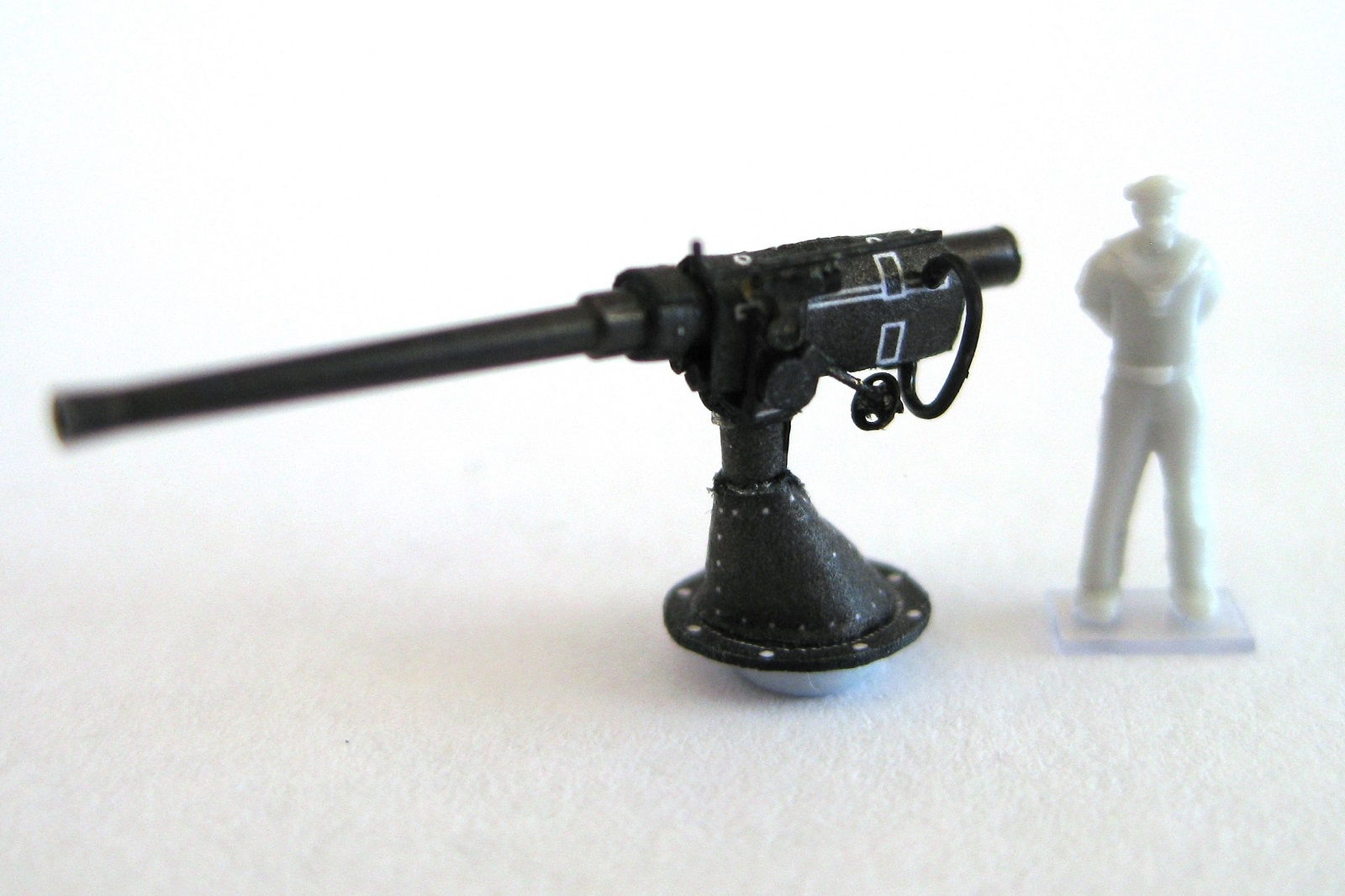
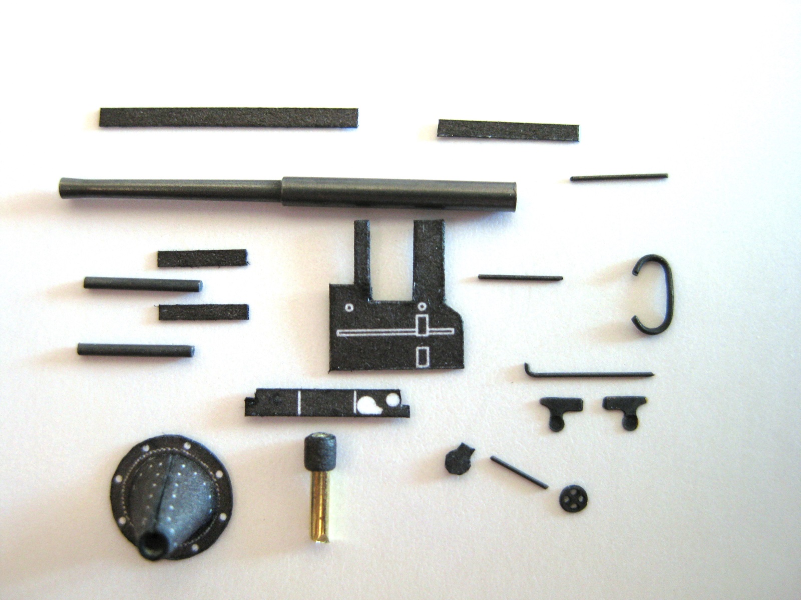
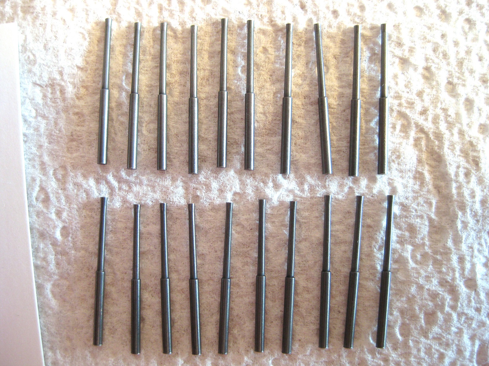
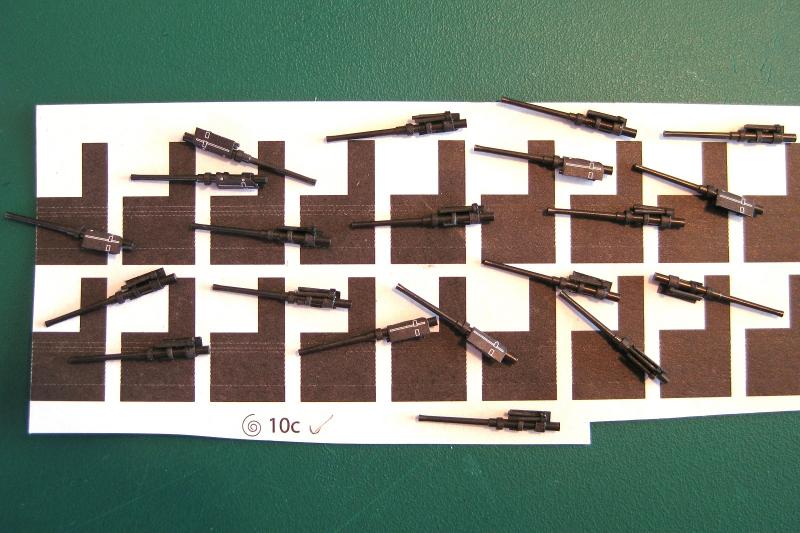
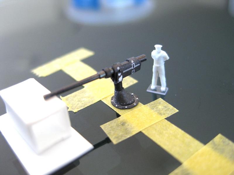
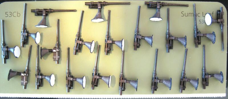
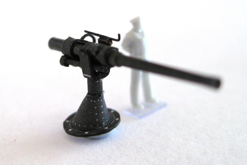
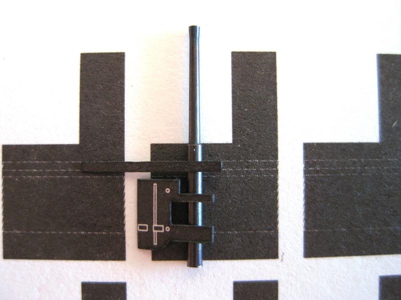
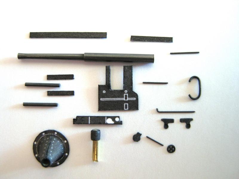
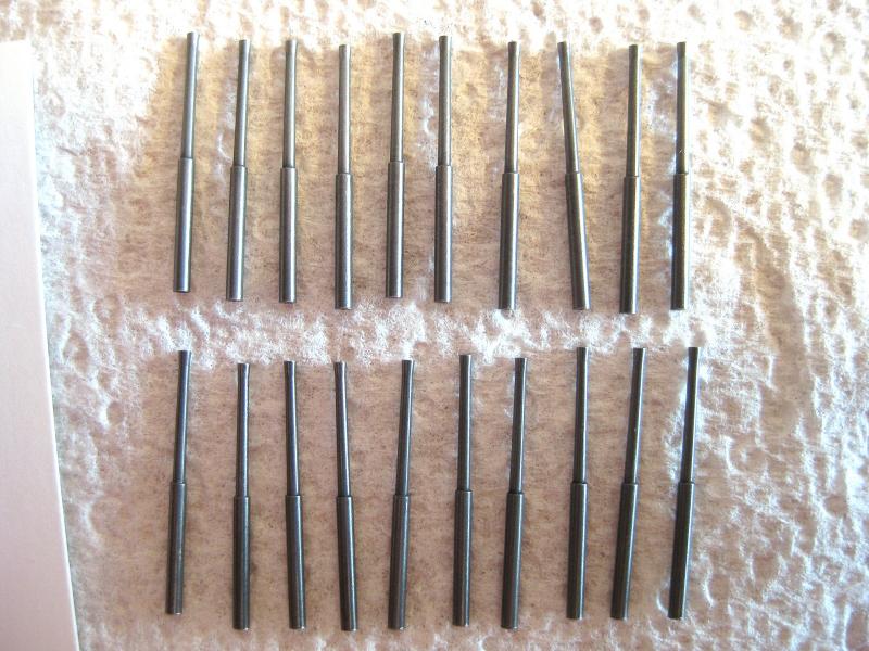
Thanks Joe and to everyone for the likes. Progress continues on the barrel assembly. Starting from the left of the photo we have the parts necessary to do the assembly. The barrel, a paper strip to form a band, a side plate to wrap the barrel and finally 2 dampeners? The next barrel along shows the strip wrapped round the barrel; done by gluing one end to the barrel and then gluing and wrapping as detailed in an earlier post. The next 2 barrels show the side plate attached from a couple of angles. The 2 thin arms were tacked to the barrels by their ends and then wrapped partially round the barrel. The wrapping of plate showed up the paper issue again with the paper delaminating on the thin arms when the flat plate section started wrapping round. By modifying the technique I reduced the de-laminating a bit but couldn’t eliminate it. The last barrel shows the 2 dampeners glued to the underside by their thick ends only but they will be trapped between the pivot uprights so that’s fine. What is missing and I choose to leave off is another dampener rod which should glue to the front collar and go backwards between the 2 thicker dampeners. These were only 0.2mm rod with a small strip wrapped round them in a similar fashion to the larger ones. Again I found it impossible to wrap tiny pieces of paper round even tinier pieces of brass. I can live with it. All twenty barrels ready for mounting into their pivots. A few points of note; the side plate attachment were tricky due to the de-laminating problem which also a caused a number of the plates being slightly angled. The twin dampeners aren’t as neat as I would have liked also but again for what will be seen I am happy with them. A few shiny glue areas are visible up close but once the guns are complete I will reassess and if I think necessary I will spray them all with Matt Cote. Next up was to mount the barrel assembly into the pivot and then fix the pivot to the pedestal. I held the pivot in the pin vice and placed a dab of glue to each upright and then placed the barrel between squeezing together once positioned. The pivot and attached barrel were removed from the pin vice and gripped on the paper collar with tweezers and the brass pin coated with glue and reinserted back into the pedestal and using a styrene packer the barrel was set level (hopefully). Upside down Tamiya tape was used to hold the pedestal down whilst gluing and setting the barrel height. All twenty barrels fixed to the pivot and inserted into the pedestals. (paint colour test cards from the hardware store are handy for a number of uses, particularly for dispensing blobs of glue on to, to then pick up from with a needle or brush. I use a lot of old business cards for this also) With the above completed it was then a matter of attaching the top bracket and rod, the hand wheel /gearbox and then the handle. The gun looks a lot taller than the scale figure as it is sitting on a blob of blu-tack as the brass barrel makes it very front heavy. Got a confession to make, I did a total of 5 guns to the stage as in photos 5 and 6 but then ended up not continuing to attach the rest of the ancillary parts for the remaining guns as frustration got the better of me with the hand wheels and gun sight continually falling off. Once I determine the most visible position I will place the more detailed ones there. I am not too concerned with not fully detailing them as will mostly be hidden anyway and this is supposed to be enjoyable, not an exercise in pig headedness, slogging (pun intended) through it. Finally at a stage to skin the upper hull. Cheers Slog

- 244 replies
-
- 14
-
-
- borodino
- dom bumagi
- (and 1 more)
-
Hi Greg, Really enjoying following your build particularly the photo-etch. I am hanging out to see what new PE assembly is coming next. Bit jealous with all the PE you get to do for these 1/350 scale ships as I would really enjoy doing this amount. I have a couple 1/200 scale plastic builds (with Pontos or MK1 upgrades) I have in mind to get in to the full-on Photo Etch work although will be a good while down the track at the rate I build at! Cheers Slog PS forgot to say the work to date is impressive indeed and very inspiring!
-
Hi DR, Really enjoying following this build and the work you are doing. With regards to the masking, in another forum for a similar build the builder masked the lines from scratch by laying down 2 full length strips of mask with the correct width gap between them and then filling in the space with lots of short strips of mask to leave individual gaps. May be an option if the Pontos stuff doesn't work out right. Good to see they actually provide the mask in the 1st place though! Cheers Slog
-
Great to see you are back in the shipyard Steve. Looking forward to following along again Cheers Slog
-
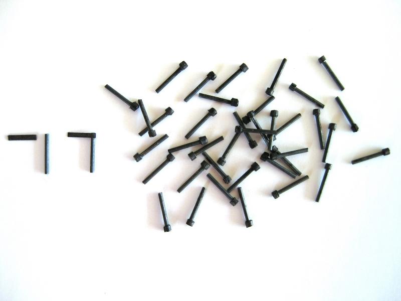
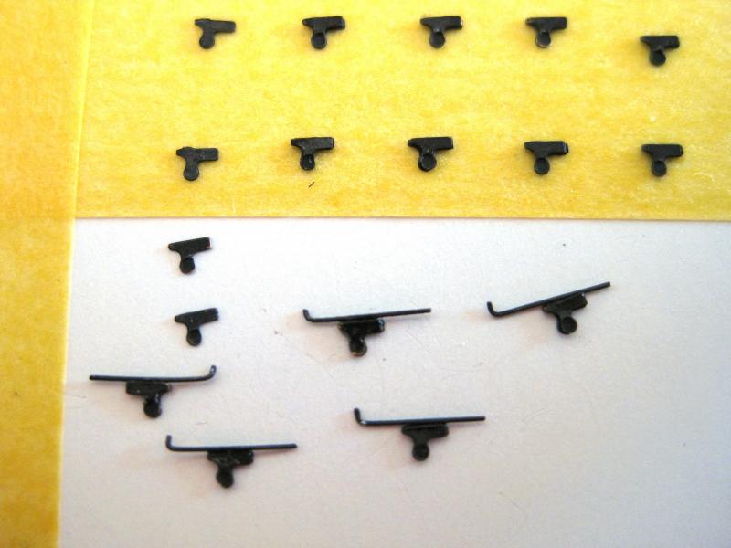
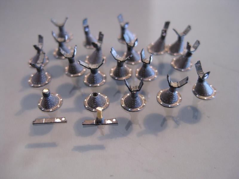
Hi All, It’s been a while since my last post but although still doing FIFO for work my R&Rs are free again so it’s back to working on the 3” casemate guns. Progress for this swing is working on the sub-assemblies. I think these are recoil shock absorbers/dampeners? There are 2 per gun for a total of 40. I first glued the small paper strip the end of the 0.5 brass rod. Once dry I held the rod in a pin vice and coated the backside of the paper with glue. Pressing my finger against the paper I rotated the pin vice slowly wrapping the strip on top of its self. These were pretty simple to do. The next sub-assembly has a side bracket with what might be sighting rod on it? I replaced the paper bracket with the photo etch parts. The photo etch bracket comes in 2 halves which are handed so after shorting into 2 piles I stuck all of the same side on to Tamiya masking tape to hold in position. The stuck down parts got a dab of CA glue and the other half pressed down to it. The previously formed 0.2mm brass wire was glued on top. A couple of problems encountered here. I think the blackening might be interfering with the CA bond as a few of the brackets fell apart easily also a few of the wire parts were difficult to get a good bond. Also the war of attrition took its toll on the bent wire parts due to pinging off into the ether. Rather than go to the trouble of making new bent ones I just stuck some spare straight parts I had on instead. Pretty slack I know but…. Next up is the gun elevation hand wheel. I think from the plans the 0.2mm spindle is just stuck to the edge of the paper part. I didn’t think this would be strong enough so actually glued the spindle to the back of the paper part. The spindle was then gripped with tweezers, dipped in some CA and then pressed to the hand wheel. Again I think the blackening is interfering here as I had a hell of a trouble getting the spindle to stick to the tiny hand wheels. I have previously make some dual 37mm cannons for my Bismarck build from photo etch and never had problems gluing the tiny bare brass parts together. Further work done on the pedestals which were detailed in an earlier post. The small paper strip folds to form the gun mount uprights. These were easy enough to do; gluing the strip to the end of the swivel and then folding up. Despite scoring the bend marks some of the bends bunched up in the corners but not a problem as this will be hidden once the barrels and dampeners, from photo 1 above, are in place. The last sub-assembly are the gun barrels. I mentioned previously I couldn’t roll the paper barrels satisfactorily so I decided to use the brass barrels bought separately at the same time as the ship. The barrel and the breech of the brass replacement gun are slightly longer than the paper part. To get a datum for attaching the paper parts I will align the brass and paper barrels at the change in section diameter for consistently. The paper part has thin lines printed on them and I will use these as reference for attaching the other parts to the brass barrels. That’s it for this swing. Next time back will be for 3 weeks Christmas break so hope to get a fair amount done during the holidays. Cheers Slog

- 244 replies
-
- 14
-
-
- borodino
- dom bumagi
- (and 1 more)
-
Hi Les, The Caldercraft Endeavour provides the correct shape windows as photo-etch and the stern decorations similar to the AOTS in white metal. I am not sure if this is still the case but Cornwall Model Boats used to stock all the Caldercraft components individually including Endeavour so it might worth checking there for the bits you want. Cheers Slog
-
Looking great Greg. Brass/metal barrels look so much weightier and more realistic than the plastic ones. As Pat says the blast bags look good. There are no aftermarket blast bags for a future build of mine and looking into different methods of making them from putty, tissue etc. Not looking forward to that as I imagine it will be difficult to get them looking as good as aftermarket resin ones. Cheers Slog
-
Hi Nick, Your progress is looking really solid and you should be left with a strong stiff skeleton for skinning. With regards to to placing your photos with-in the text here is what I do. 1. I type all my text in Word first as I can type as long as I want without worrying about MSW timing out although not sure if that is an issue or not. 2. Click more reply options and then copy and paste the text from Word in to the text box. I put a couple of spaces with-in the text where I want to place my picture and type place holders such as PHOTO1, PHOTO2 etc 3. Go to below the text box and click the "Choose Files..." button under where it says attach files. 4. Select all the photos and upload them all in one hit. 5. Go back into the main body text and delete your place holder 'PHOTO1' and where the curser is flashing is where the photo will be inserted. Go to the list of uploaded photos and click insert. It will upload the photo. 6 Go to your next placeholder and again delete the PHOTO2 words and click insert for the next desired photo and continue on until all your uploaded photos have been inserted where you want. Cheers Slog
- 20 replies
-
- 2
-
-
- maly modelarz
- Batory
- (and 1 more)
-
Hi Nick, Good to see you are continuing with the build. With regards to accuracy sometimes you will be butting joints on a 0.5mm former so accuracy is paramount as you have discovered. Also sometimes it makes a difference if you cut on the line or either side of it! Saying that I have a subconscious habit of cutting outside the line which adversely effects my joints sometimes. Like you I like how easy it is to do a bit of modelling with minimum fuss, a knife and ruler most times is all you need to make some progress. Looking forward to seeing more. Cheers slog
- 20 replies
-
- 2
-
-
- maly modelarz
- Batory
- (and 1 more)
-
Thanks Greg, I checked them out and they look fantastic and the pictures cleared up an issue I wasn't sure about. You are certainly on top of all this after market gear! Also from the site I learned that they are Canet guns on Meller mounts, great stuff! It gives me alternatives if I mess them up as was thinking if that happens I will just have to close the hatches and not show them. Cheers Slog
- 244 replies
-
- 5
-
-
- borodino
- dom bumagi
- (and 1 more)
-
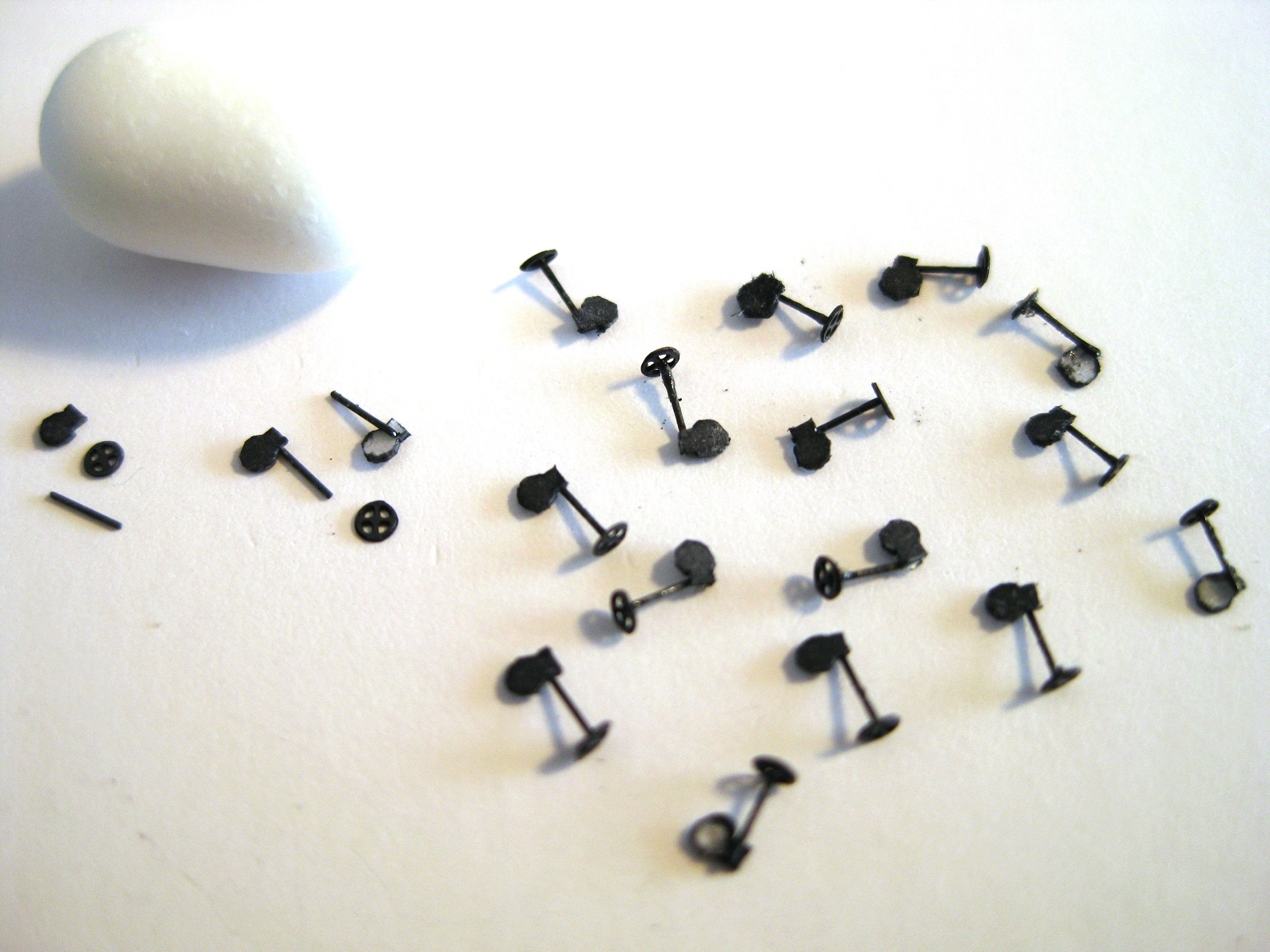
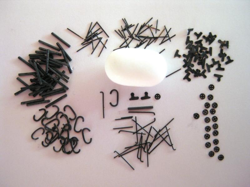
Hi, After my previous post I cut out the last of the paper strips which are rolled round the various sizes of wire. That's everything ready for the final assembly. For a bit of fun/inspiration but which actually turned into a "oh crap how am I going to put 20 of these together" moment instead I laid out all the parts for one gun assembly. LOL That's all for this time and it'll probably be a couple of swings before I can work on them again, but at least I have something to look forward to Oh and I was finally able to find one picture on Google images showing this gun and the pedestal orientation is with the offset hole/vertical face at the front of the gun and the sloping section with the seam at the rear. Cheers Slog
- 244 replies
-
- 11
-
-
- borodino
- dom bumagi
- (and 1 more)
-
Hi Sam, To clean up small parts I lay them on some kitchen roll or a soft cloth and then use an soft paint brush and scrub them with that. It usually gets off everything but the most stubborn bits. A stiffer brush can be used for them. Incidentally I tried something similar to your thoughts tonight. The 0.5mm thick! wire was placed in a container and I put in some suger and gave them a good shake for a while. It obviously works as the sugar lost its white colour and the powder came off the wire. As I mentioned they still look a bit dark so will need more work to fully clean them. I had a look at rolling the container and it had a nice flowing action in it with the sugar so thinking I will attach it to a drill and turn slowly for a lot longer. With regards to losing parts after I picked out all the obvious pieces I poured in boiling water to dissolve the sugar to see if anything was left behind LOL Cheers Slog
- 244 replies
-
- 4
-
-
- borodino
- dom bumagi
- (and 1 more)
-
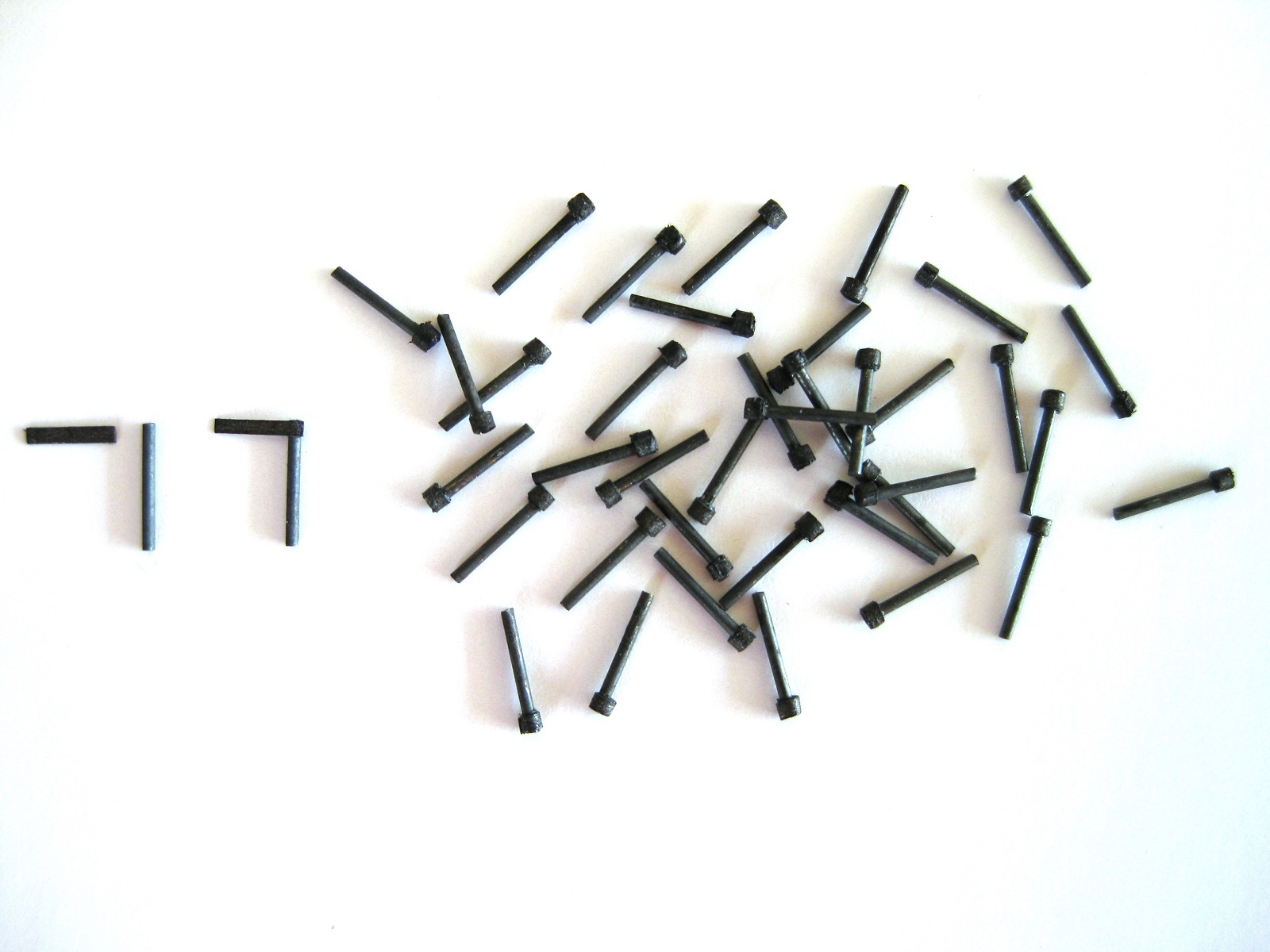
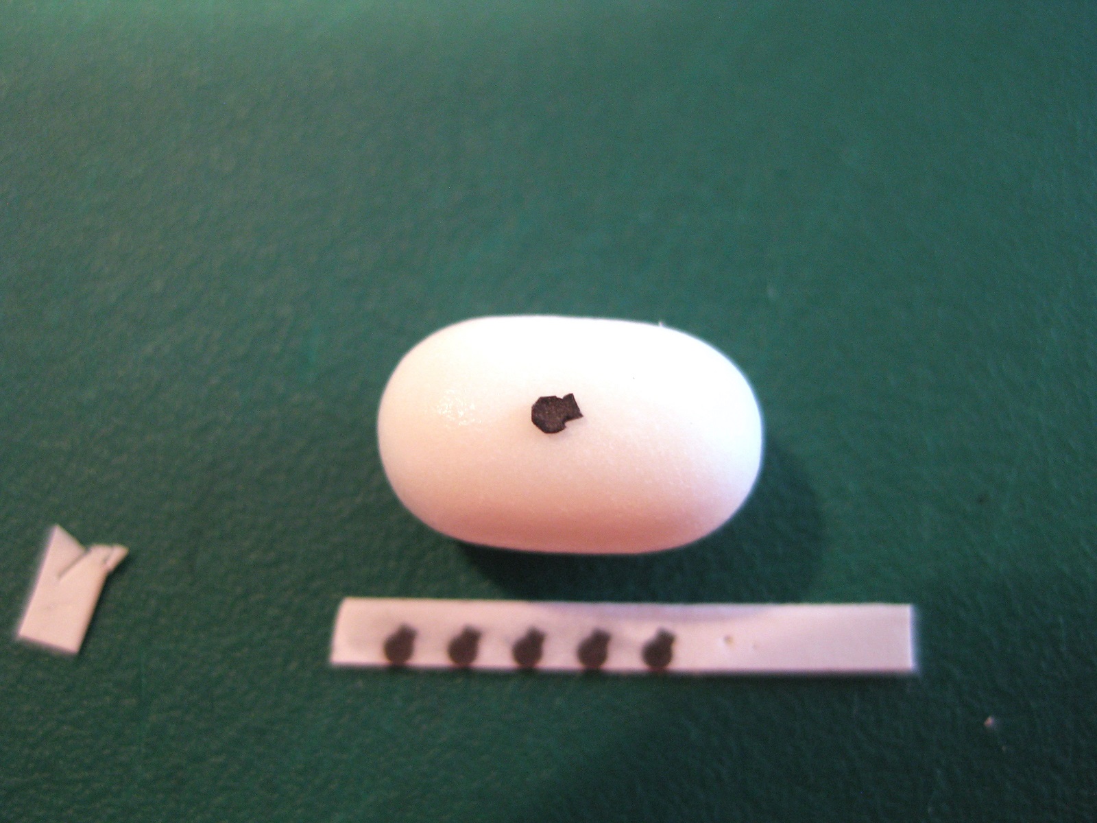
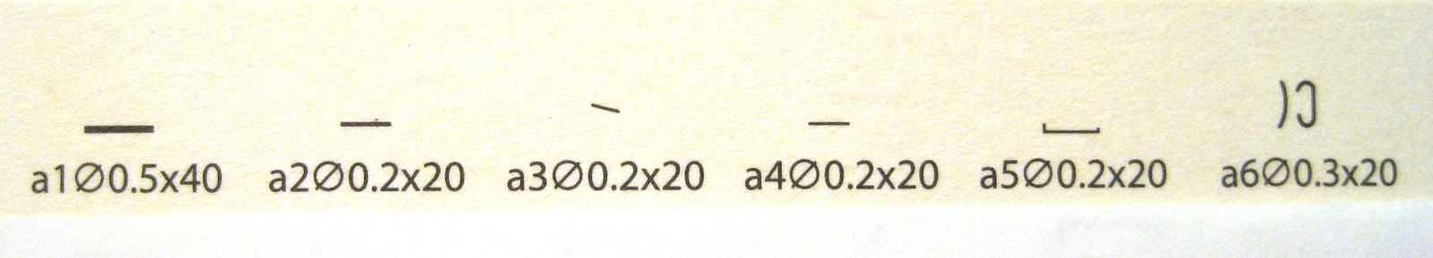
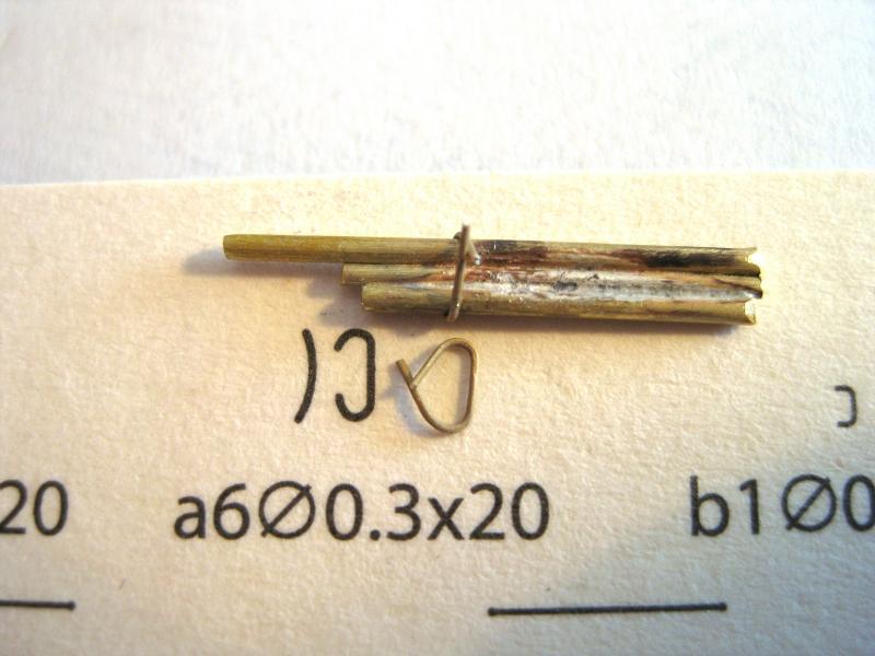
Thanks for the comment David and all the likes. The processes can be applied to any card model, I am just picking parts from this build to elaborate on. I don’t have the patience to teach! LOL Continuing with the 3” gun parts. This part must be the gun elevation gear as it has a spindle and hand wheel coming out of it. This is probably the smallest paper part so far on the build. I tried a couple of times just cutting them straight out but the paper was just falling apart so I coated both sides with CA glue and it was fine after that; like cutting very thin styrene. The macro shows it a bit boxy looking instead of round but to be honest I was struggling to see it even with the head magnifiers on and once assembled won’t be noticable. The last bits of paper to cut are all the thin strips so decided to do the ‘iron work’ next as per parts a1 to a6 as detailed in an earlier post. Most of them are just different lengths of straight wire but part a6 is a curved handle. I soldered a few tubes together of the same diameter as the diagram and used this to bend the annealed 0.3mm wire round to get the correct shape rather than try and bend each piece freehand. Photo shows a part in the jig and another ready to get the legs trimmed to length. The time finding and soldering the tubes together sped up forming each part immensely. The handle also has a curve to it as shown in the diagram in the photo above and just happens that the knife handle matches the curve in the diagram. So it was a matter of laying the wire handle on the knife handle and then using a soft pencil eraser, pressing down to form it. The rest of the wire parts were cut to length as per the diagram and blackened. I used my usual technique for blackening which I have done in the past with acceptable results. Firstly I soak the brass parts in hydrochloric acid for 15-20 minutes (although should have left longer in this case) followed with rinsing in water. The parts are then placed in neat Caseys Brass Black for 4 minutes then rinsed with water again before cleaning of the black powdery residue. The photo shows 1 example of each of the parts a1 to a6 as well as the replacement photo-etch hand wheels and a pair of brackets that need gluing together. Here is a photo of all the ‘steel’ parts. Some of them still show areas of brass but I will just touch them up with a black felt tip marker when assembled as really tiny and don’t warrant the whole blackening process again. Also some of the parts could do with a further cleaning as they still look quite black which suggests they still have some black powdery residue you get with blackening. Again I will clean them up as I use them. I also blackened the 3” gun barrels and these came out pretty good. After blackening and rinsing they were buffed with a soft cloth and I like the colour this leaves although could be a bit darker. I am going to use the brass barrels as I tried to roll the paper ones and honestly I couldn’t do it. I might continue trying to roll them for practice but won’t be using them. I am more or less ready to start assembling the guns although I did run out of 1mm brass rod for the pedestals but have some tube I might try and use Cheers Slog

- 244 replies
-
- 12
-
-
- borodino
- dom bumagi
- (and 1 more)
-
Hi Dave, Looking good and making good progress Probably just as well they didn't fit as I am led to believe Hexagonal nuts and bolts didn't exist at the time of Endeavour. Possibly square heads but don't know for sure. Cheers Slog
-
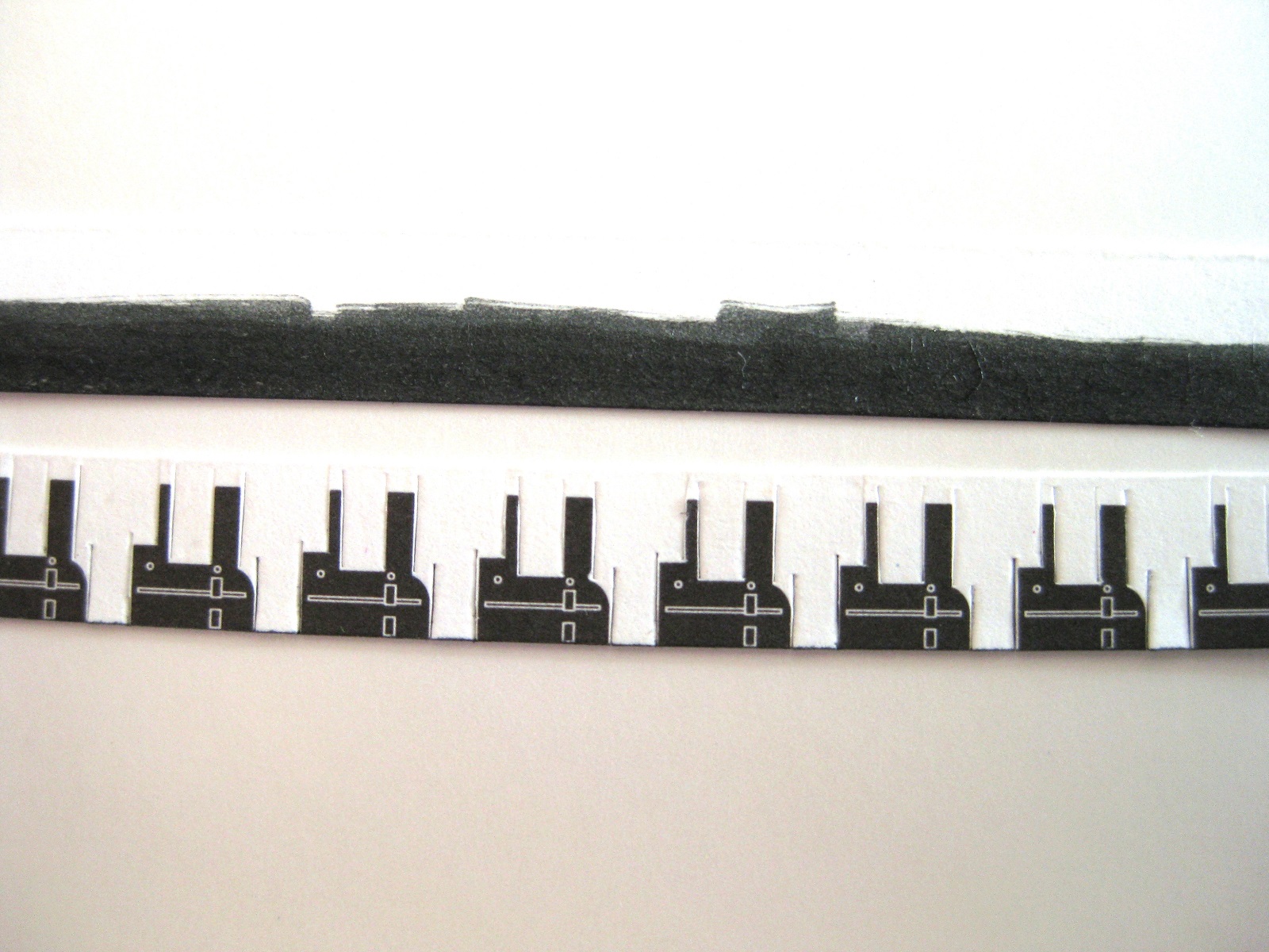
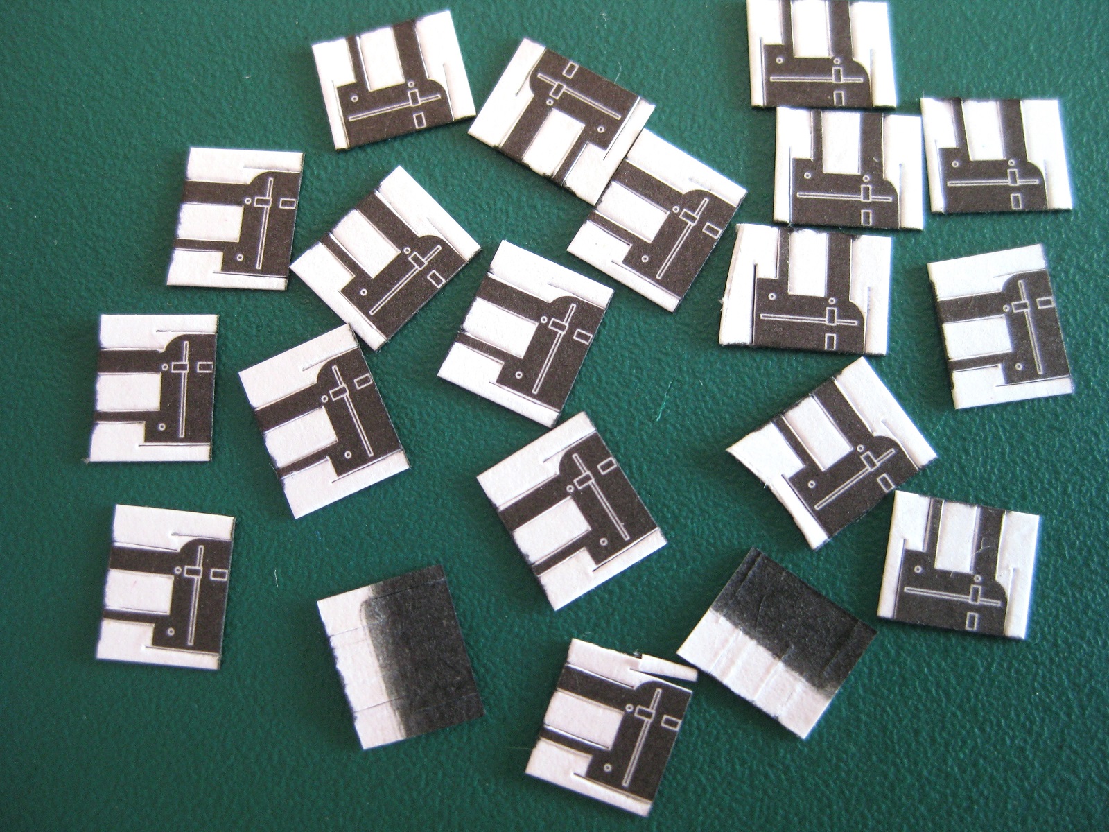
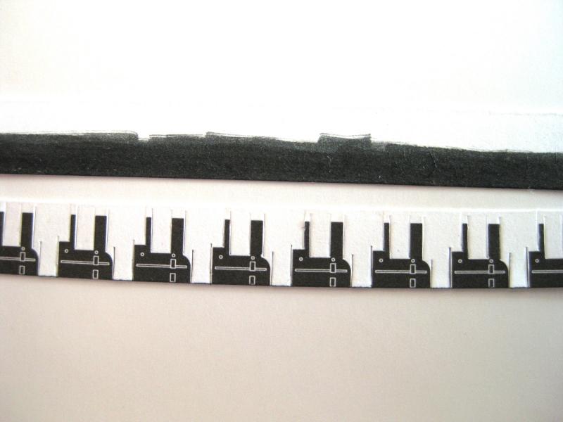
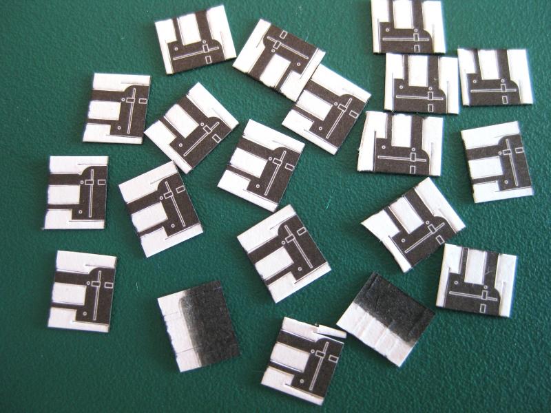
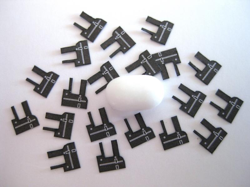
Thanks guys for the comments and well wishes, appreciated. Scott, we appear to have similar experiences. Did close to 7 years FIFO including Area C twice, Newman Hub, Marillana (beside Yandi), Marandoo, Karratha (built the GRV camp and then closed out Pluto), Karara (that was DIDO until we built the airstrip) all good memories then 3 ½ years metro. I actually started my Endeavour build as something to occupy myself whilst on R&R which is a bit of a worry as that’s 10 years give or take now! Panama Port, unfortunately a necessary evil. As my mum says “I wish I was born rich instead of good looking” LOL Okay got back in last night and did a bit of modelling this morning. I thought I would cover a few more snippets using part 10d as example. This is a plate which partially wraps round the gun barrel as per the diagram in a previous post. The parts were cut in to 2 strips of ten parts each. Rather than edge colour little parts individually do your edge colouring progressively for ease of handling. The 2 strips were cut along the final bottom edges so took the opportunity to edge colour the whole strip edge. Also as part of the backside will be visible, colour the whole area as shown in the top strip, rather than individual parts again. The bottom strip is a good example of planning the order of your cuts. The section needing protecting here is the thin sticking up part as this is only about 0.5mm wide. By doing all the vertical cuts 1st the part is prevented from deforming by the white waste material all round it. Okay with all the vertical cuts made, I separated the pieces into the individual parts and again thinking of protecting the sticking up elements I chopped these to length as they have plenty of ‘meat’ each side and finally edge coloured the tops as per the photo. With that done it is now a case of removing the last of the waste material. Firstly the straight horizontal cut was made totally freeing one side. The curved other side was made by 2 or 3 cuts to have an illusion of a curve totally freeing that side and finally a chop cut to free the centre waste. They didn’t turn out to bad although a couple of dodgy ones in there, but by the time they are wrapped on to barrels and fully assembled should be good. I mentioned previously I don’t like the paper in this kit and think the parts may have been a bit sharper with better paper but still happy with them. Currently working through all the other little bits and pieces for the guns as time allows. Cheers Slog
- 244 replies
-
- 9
-
-
- borodino
- dom bumagi
- (and 1 more)
-
Hi Nick, Great to see another card model appearing in the build logs. Looking forward to following your progress. I agree with your philosophy. I usually at least attempt the part but if not happy will try alternatives. I find additional replacement parts of photo-etch etc really sharpen up a build in some areas. Do and use whatever it takes to make you happy with it. You will ask the same question many times as you progress through the build. "They want me to make that using this!?" I think once you get in to it you will surprise yourself with what can be done. Cheers Slog
- 20 replies
-
- 1
-
-
- maly modelarz
- Batory
- (and 1 more)
-
Brilliant work! I must be a bit strange, but I probably find doing that type of work the most enjoyable, certainly the most rewarding! Cheers Slog
-
Hi Grant, Thanks for the detail in fibre glassing. I like your purchase of a spray gun. I am thinking along this lines for painting hulls as advised by Paul Budziks videos as my 0.3 Iwata airbrush struggled a bit for a full hull. Cheers Slog
- 339 replies
-
- 6
-
-
- dumas
- Chris-Craft
- (and 3 more)
-
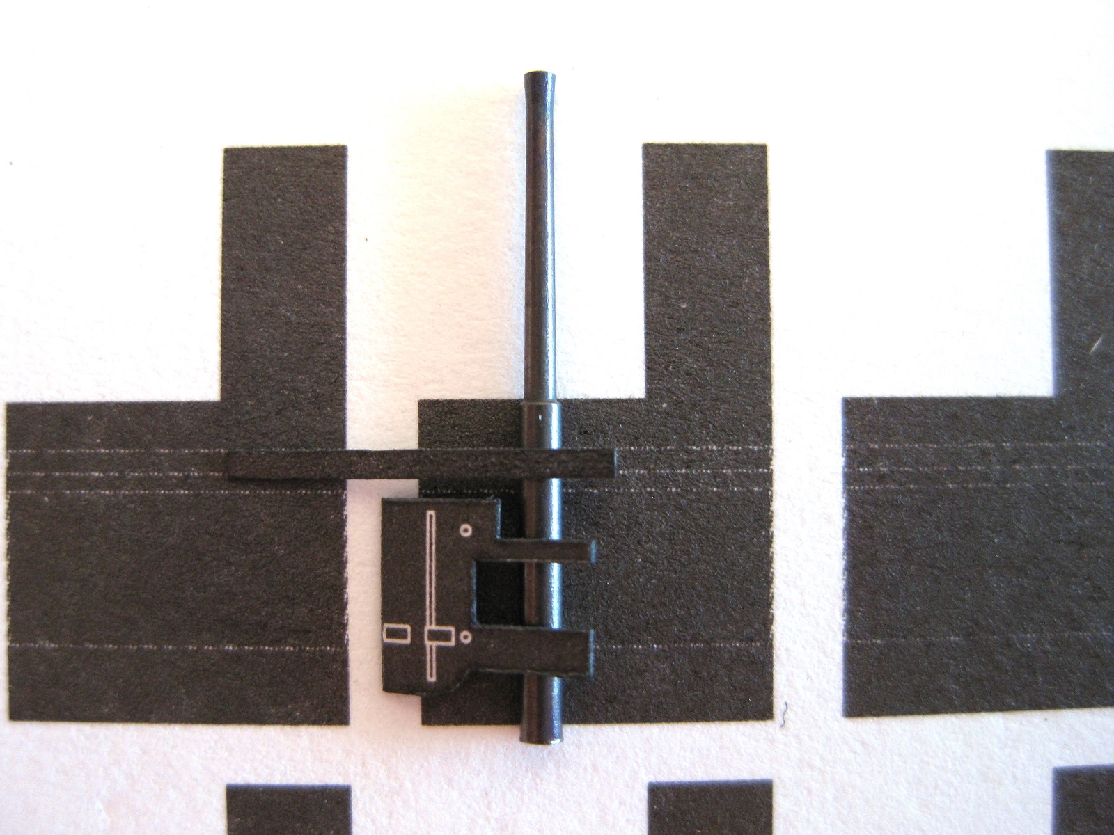
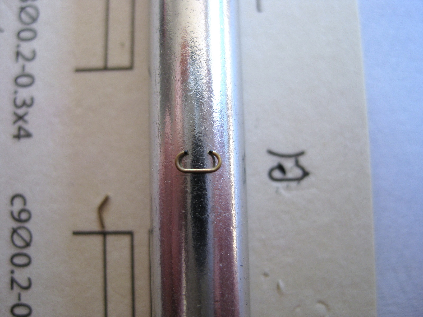
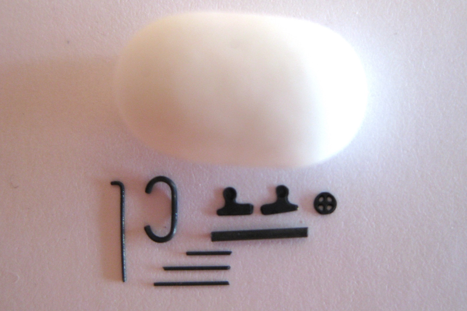
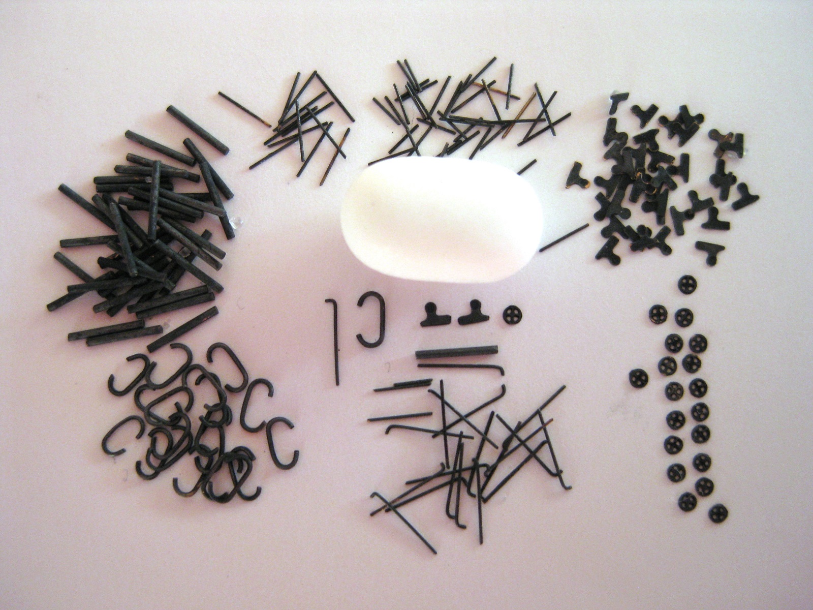
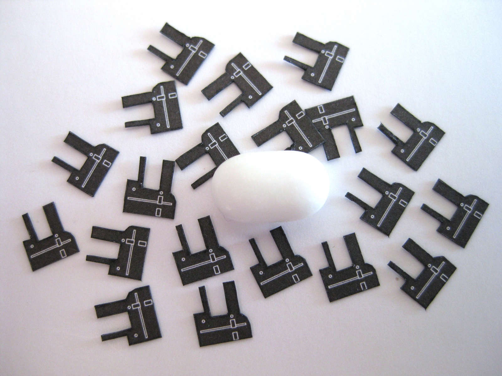
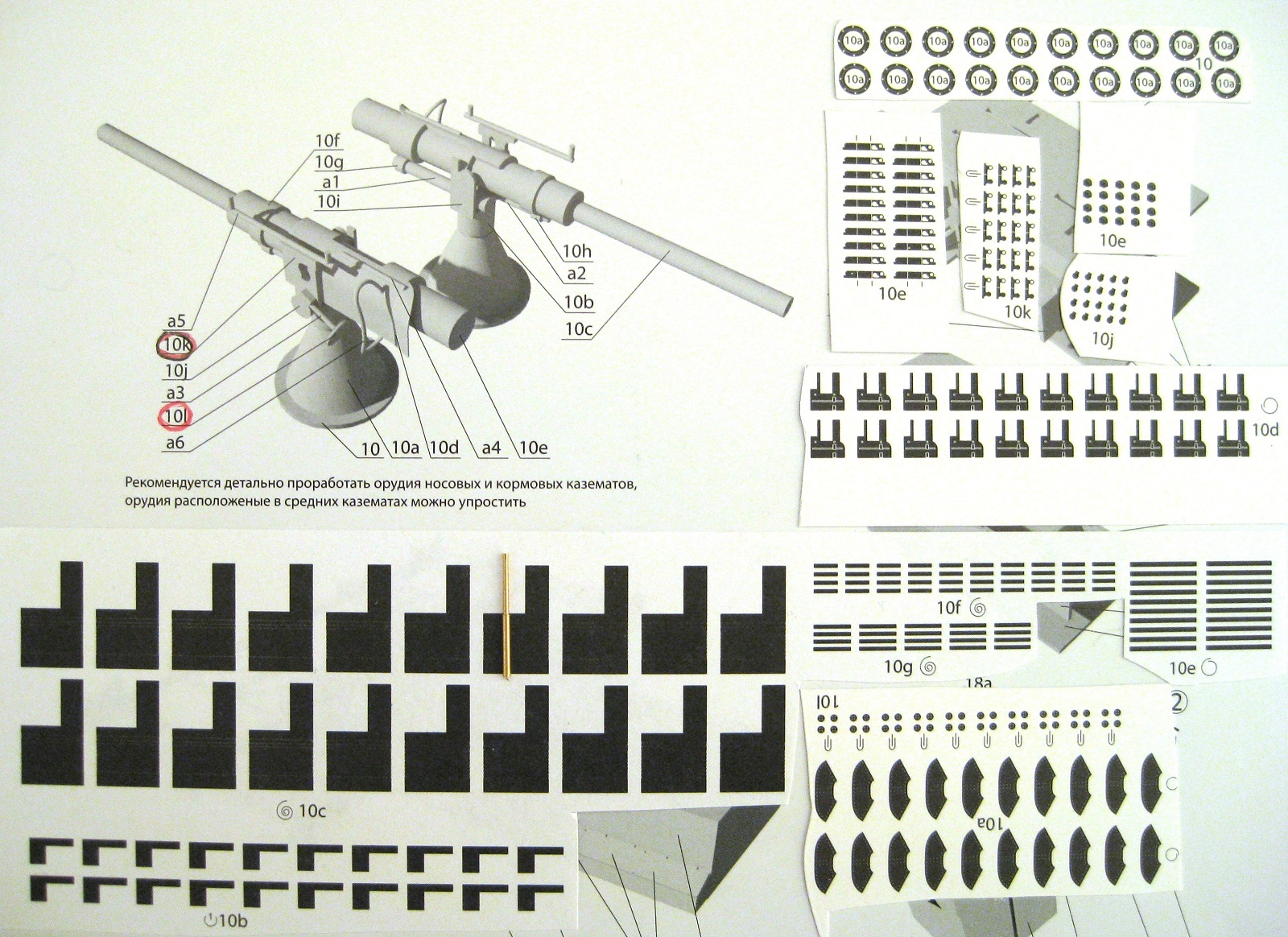
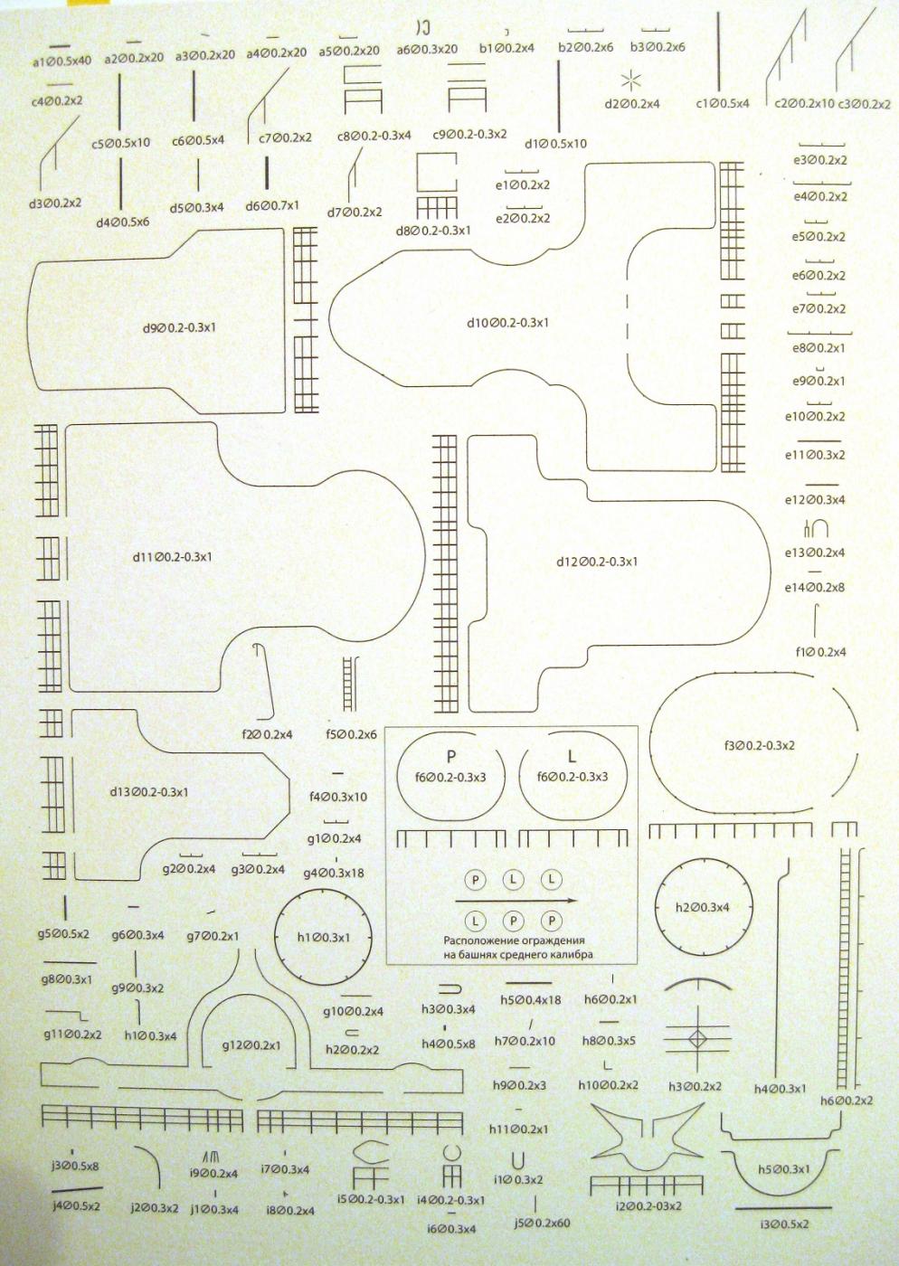
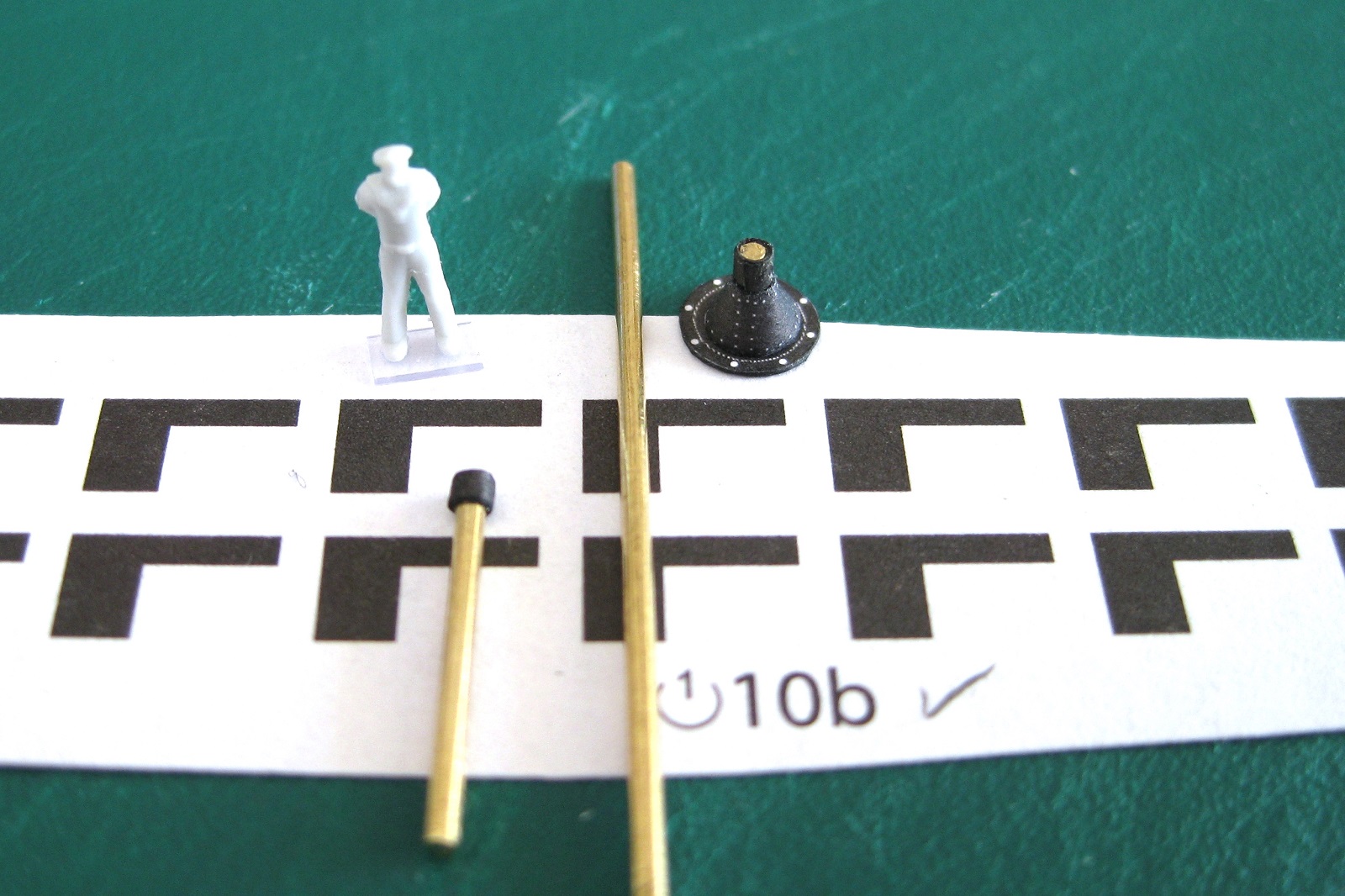
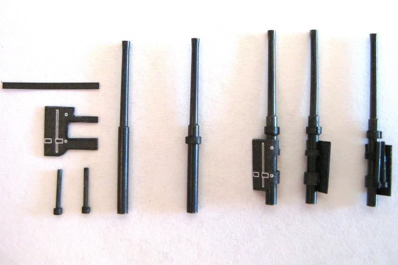
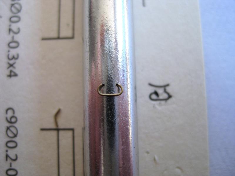
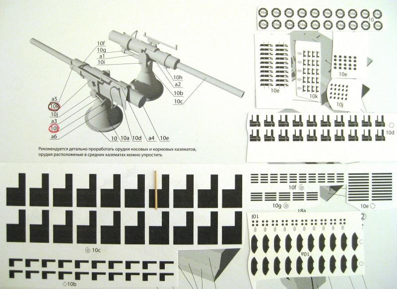
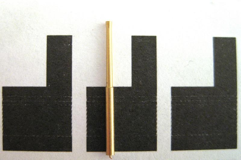
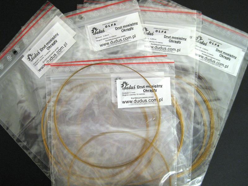
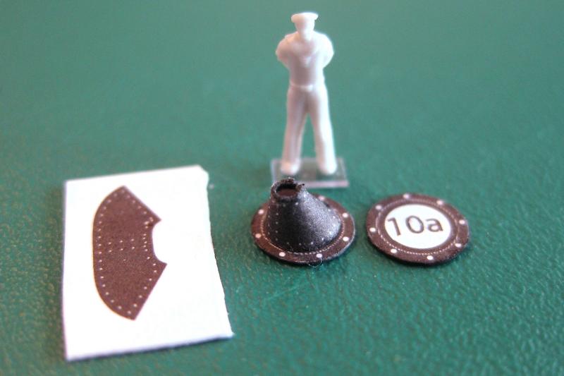
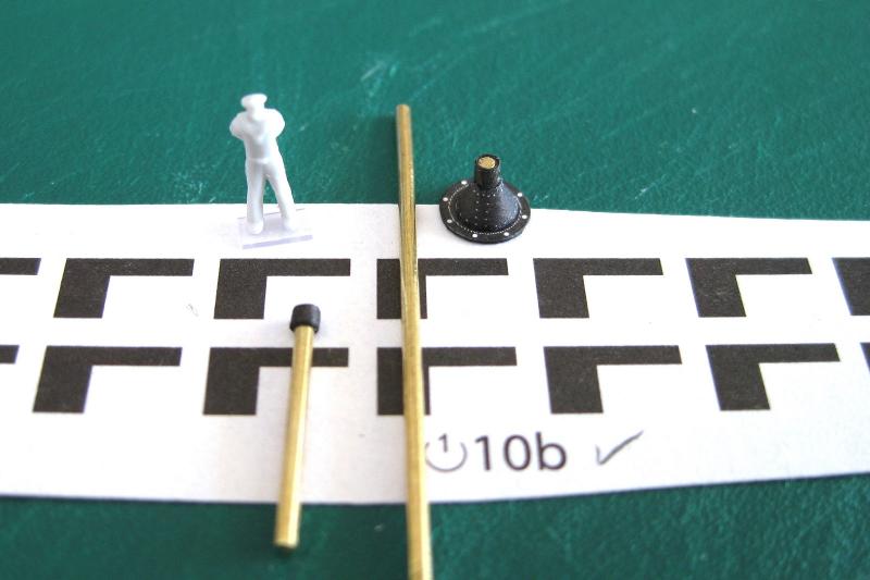
Hi all, I will be doing FIFO again for work starting next week, flying in and out of Darwin so my snail’s pace build will become even slower. The roster is 10 & 4 so updates will be fewer but it’s only for 2 or 3 months. I have started the 3” guns but will also take this opportunity to use them as an example to detail some of the ins and outs of what to expect if new to card modelling. Hopefully it will be interesting for some of you. Okay, the 3” casemate guns. There are a total of 20 of these; 6 down each side of the hull and 4 each on the bow and stern. The large sheet below the diagram and all the thin lines to the right are printed on thin paper. The remaining parts are printed on the standard kit paper. This is a good example of the typical numbering system used in card models. All publishers I have seen use numbers and letters in a similar fashion to identify the parts and assemblies. Looking at the diagram in the photo below the 3” gun assembly is number 10. All associated paper parts use the assembly number followed by a letter to identify the unique part. As the gun assembly is 10, the first part (the gun mount base plate) is 10 and the second part (the pedestal) is 10a and so on and in this case goes up to letter l (L) for a total of 13 parts in this case. (12 letters plus the original number 10) All component parts are lower case. Sometimes upper case is used for assemblies. The 1st part numbered of an assembly is usually the part which would be glued to another assembly so starting the numbering with the base plate makes sense as this is what would attach to something else. It also likely that the parts are numbered in the desired assembly order but don’t rely on this as sometimes they are just arbitrary or perhaps not in the most logical order. The eagle eyed among you will notice a typical card model issue with typo’s in the numbering…there are 3 different components all numbered as 10e!!! Not only that, but the thin strip parts f & g are also incorrectly labelled. By studying the diagram and the shape of the parts the correct 10e was determined. I needed to study the dimensions and number of the wire parts and through a process of elimination corrected the thin parts f, g and e. I also question the legend accuracy as I think they should be wrapped not rolled. I have circled part 10k and 10l in red (a side plate and hand wheel) as a reminder that these are supplied on the photo-etch detail set. The above photo only has one example of showing the relationship of parts but if you look at the base plates, part 10 (top right) it has 10a written in it, which shows that part 10a fits to this one. This example is pretty self-explanatory from the diagram but if there are a lot of similar sized shapes beside each other or multiple layers of components then it makes more sense. Some models also change the colour of where to place parts. The dark green vehicle I am building uses a lighter green where the part has to be fitted to as well as the part number in red. This helps stand out if anything is missing as the different colours draws you eye to it. Part 10c (the thick reversed L ) is the gun barrels and the legend next to the number shows that these need to be tightly rolled into a cylinder. Incidentally I have placed one of the brass barrels next them. I will roll the paper ones for experience but will probably use the brass. Surprising they are quite a bit longer. Using Google Translator the Russian text below the diagram translates to “it is recommended to study in detail the bow and stern gun casemates, gun casemates located in the middle can be simplified”. Okay I am sure it isn’t a perfect translation but it is good enough to suggest to me that bow and stern guns should be fully detailed (because more visible?) and the side guns can be more basic (less visible due to location?) I will build all guns to the detail shown in the diagram because that’s how I roll LOL All pretty simple and obvious. I find though it takes a bit of time to get into synch or the same mindset with the designer’s process as each has little idiosyncrasies This assembly also has additional details to be made by the builder using different thicknesses of wire and these have the letter first followed by the number; in this case a1 to a6. To make these components you would refer to the applicable part number detailed somewhere in the plans or cover sheet. This will provide the shape of the part printed to size and shape as well as the diameter of wire to use and the number of required. Here is a shot showing about 2/3rds of all the metal work details to be made with wire and added to the model. I think this is one of this kits big plus points in the amount of extras that can be added. The GPM Bismarck only detailed a couple of jack staffs. I will try and use generic railings, ladders and stairs where I can though. The bulk of the components use 0.2mm and 0.3mm which I will cover below. There is also a number of items which utilise 0.5mm and 0.8mm but this size is easily obtained locally for me. For the wire components I am using brass wire I bought from Orlik in Poland a few years ago. I bought 2 rolls each of 0.1mm, 0.15mm, 0.2mm, 0.25mm and 0.3mm. They come in 10m rolls so should have plenty to last a while. They were pretty cheap in themselves but should only be ordered when buying other items to negate the extortionate postage from Poland to Australia. A good excuse to buy some more kits lol. Since then I have found Australian sources of similar brass wire but the cost is about the same or more for less meterage. Surprisingly the wire is very stiff, which will be good for any short straight lengths. Trying to bend tight curves causes the wire to snap but it does become soft and pliable with annealing and can then be shaped as desired. Starting with the base plates (part 10); which being small discs were cut out using the wedge slicing technique previously described for the propeller blades. The edges were coloured using the cold grey pen as usual. The pedestal (10a) looks like a truncated cone as shown by the diagram but the part has a flat edge along the bottom which suggests when rolled will not be a perfect cone shape. So I made up one to check and indeed the centre hole is off to one side. The diagram doesn’t show this offset that I can see so now the question is what side points to the front of the gun? This shows another card model issue where the diagram differs slightly from the physical part. Part 10b is the gun mount swivel I guess you would call it and is printed on the thin paper. There appears to be a couple of things wrong here also unless I am totally misinterpreting something. Firstly the legend says to wrap the part round a 1mm rod to form. As can be seen by the 1mm brass rod placed on the parts the wide section is barely wide enough to form round the 1mm. In fact I couldn’t get the edges to meet so choose to modify it a bit. The other issue is that the hole left in the pedestal top was about a 1mm anyway so even if I could wrap the vertical section round it, the thin paper part would likely deform trying to get it into the hole. This shows another paper model issue where the design should work in an ideal world but in reality and based on the modellers experience or physical properties of the medium it just isn’t possible. I decided to modify it a little bit by removing the lower section and discarding and just permanently wrapping and gluing the thin horizontal section to the 1mm brass rod as can be seen at the left, below the figure. The brass was then trimmed to length and placed in the hole in the pedestal as shown to the right. I will not glue this in until the guns are finished as I can raise the height if required and spin the gun round once I determine what side the offset hole should be in. An additional benefit is that it gives it a wee bit more weight and stiffens it up somewhat. That’s about it for a few weeks. I will still be able to access MSW just not do any modelling. Cheers Slog


- 244 replies
-
- 11
-
-
- borodino
- dom bumagi
- (and 1 more)