
Captain Slog
-
Posts
904 -
Joined
Content Type
Profiles
Forums
Gallery
Events
Everything posted by Captain Slog
-
 Wheel looks incredible, like a real one out of a classic car. Cheers Slog
- 339 replies
-
- 6
-

-
- dumas
- Chris-Craft
- (and 3 more)
-
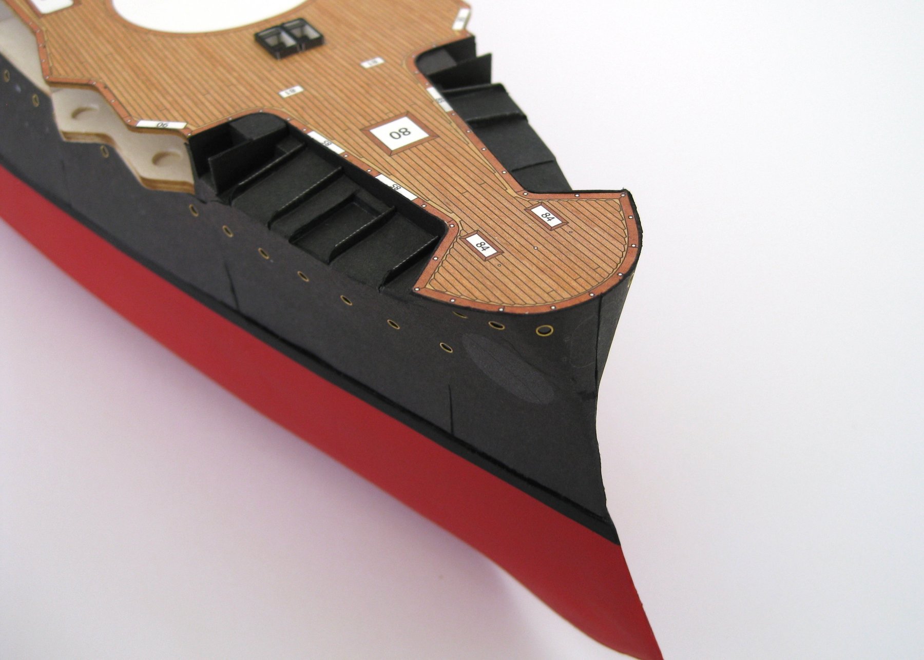
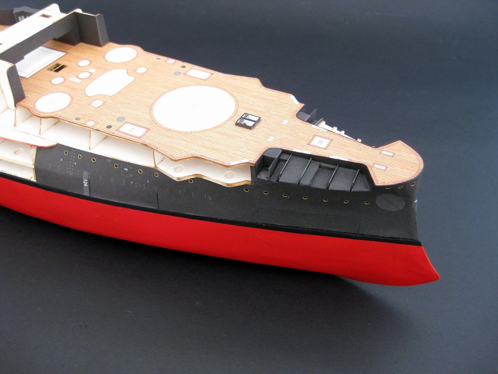
Hi, thanks for to all the likes. Continuing on, I have fitted the port bow and a side skin. Progress shot of where it is at right now. The side skin; which during the fitting dry run was a perfect fit but of course once glue is involved it was slightly off but nothing some judicious trimming and colouring with watercolours couldn't fix and I am happy with the way it is shaping up. With both bow skins fitted, which was actually worse than the starboard side and again hoping the lower belt hides most of the issues, the front is closed off and both anchor shelves completed which turned out not to bad. The centre join looks okay with the naked eye and the photo-etch eagle crest and the lower belts with a torpedo hatch should cover up most of the rest of the join. That's enough skinning for this swing. I find doing hull skins laborious and feels like I push my luck if try to do to much in one sitting. Cheers Slog

- 244 replies
-
- 15
-
-
- borodino
- dom bumagi
- (and 1 more)
-
Hi Craig, thanks for the comment. You can fill in between the bulk heads with say balsa or more card and I tried this to a certain degree with the Bismarck hull but it takes ages to do and can introduce other issues. I am going to try expanding foam the next hull I do to see if that works for me. The best thing though is to take care and not press the skin against the edges of formers with the fingers, best to use something else which bridges more than one former edge; in this case though I used my finger as it is a bit of a compound curve and I wanted to make sure it was against the horizontal former to get the curve up to the anchor deck correct. Can only learn from each piece and try and do better for the next one. Cheers Slog
- 244 replies
-
- 4
-
-
- borodino
- dom bumagi
- (and 1 more)
-
Hi all, Well I've gone and done it now; first upper hull skin is on. A bit of starved cow effect going on but happy enough. Not to worried about the lower edge or the vertical cuts as a lower belt covers most of this. Cheers Slog

- 244 replies
-
- 16
-
-
- borodino
- dom bumagi
- (and 1 more)
-
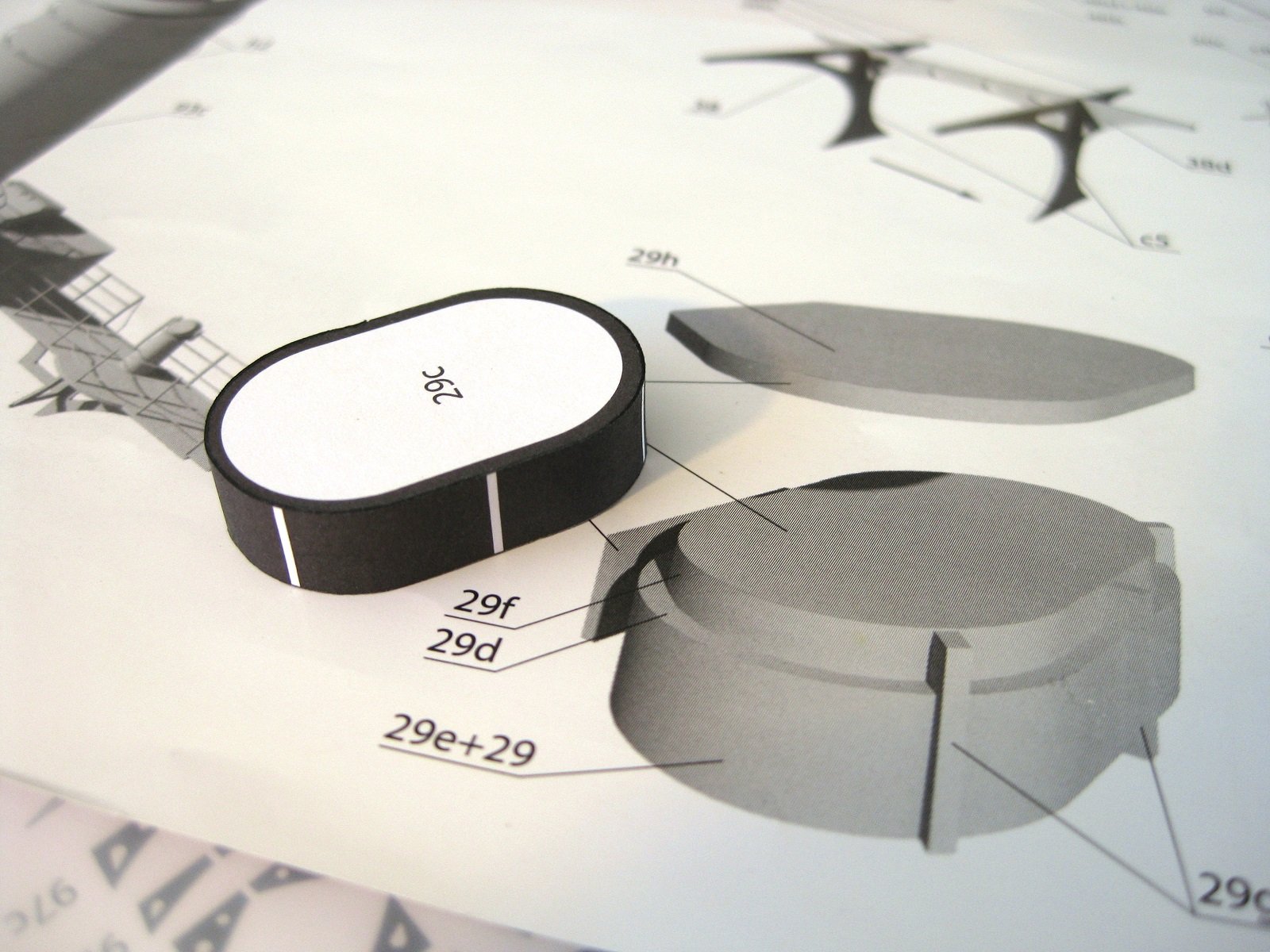
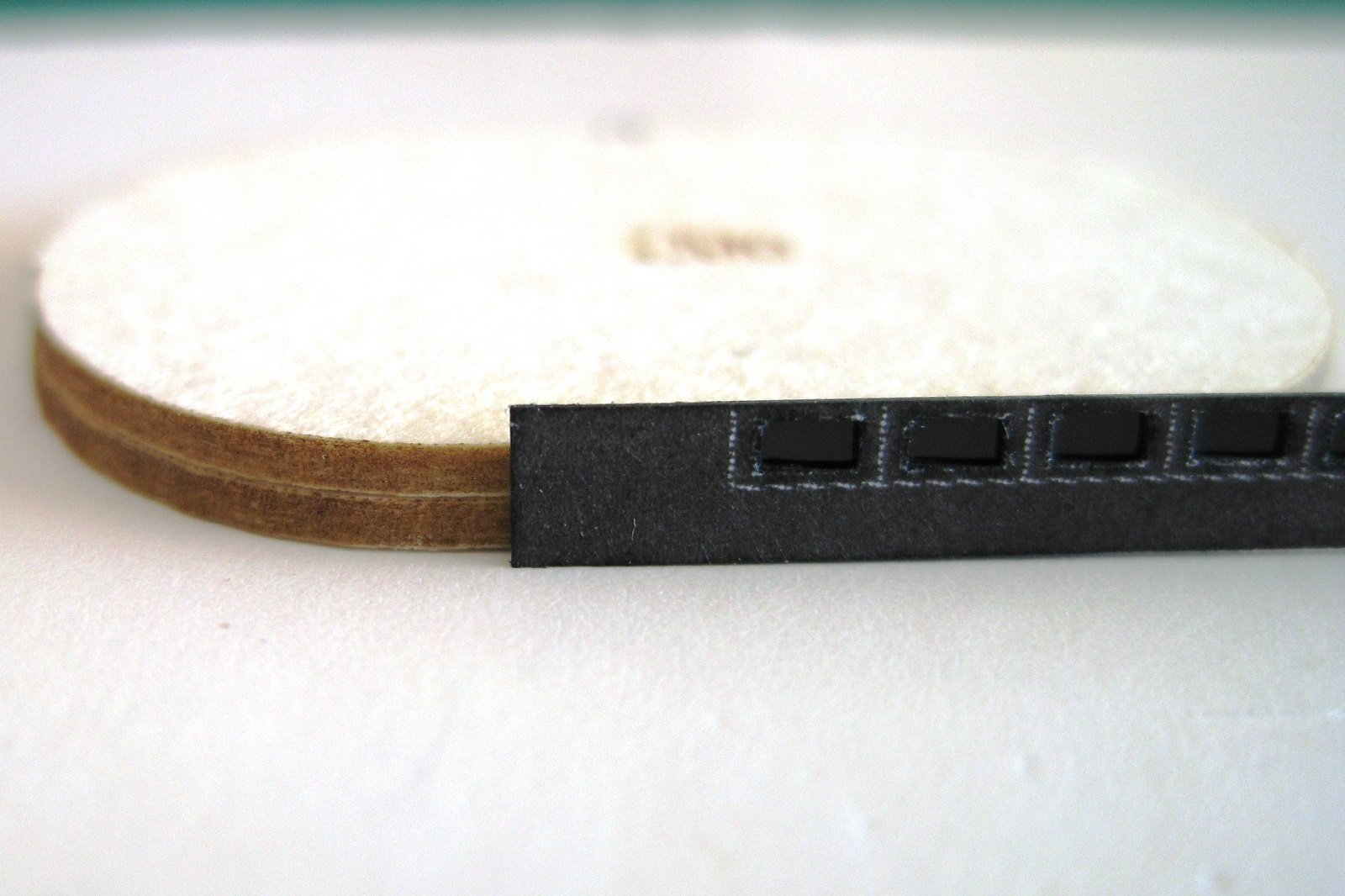
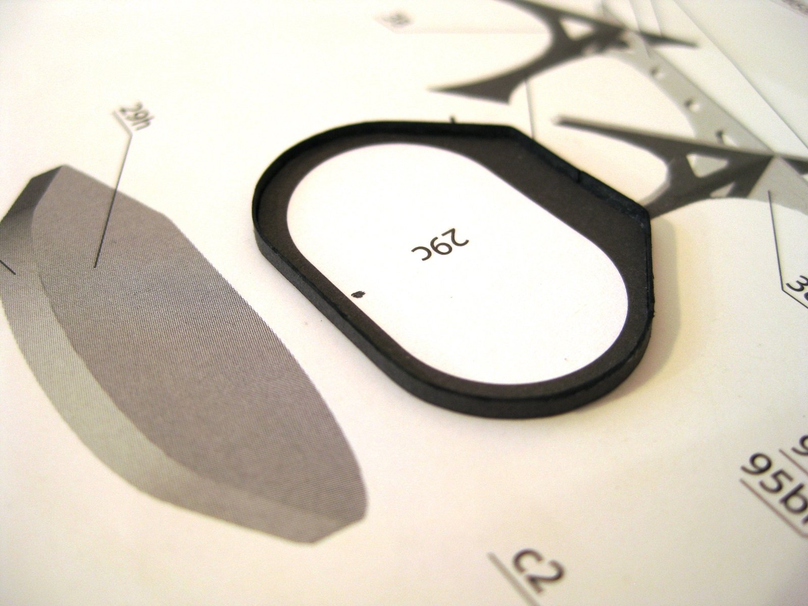
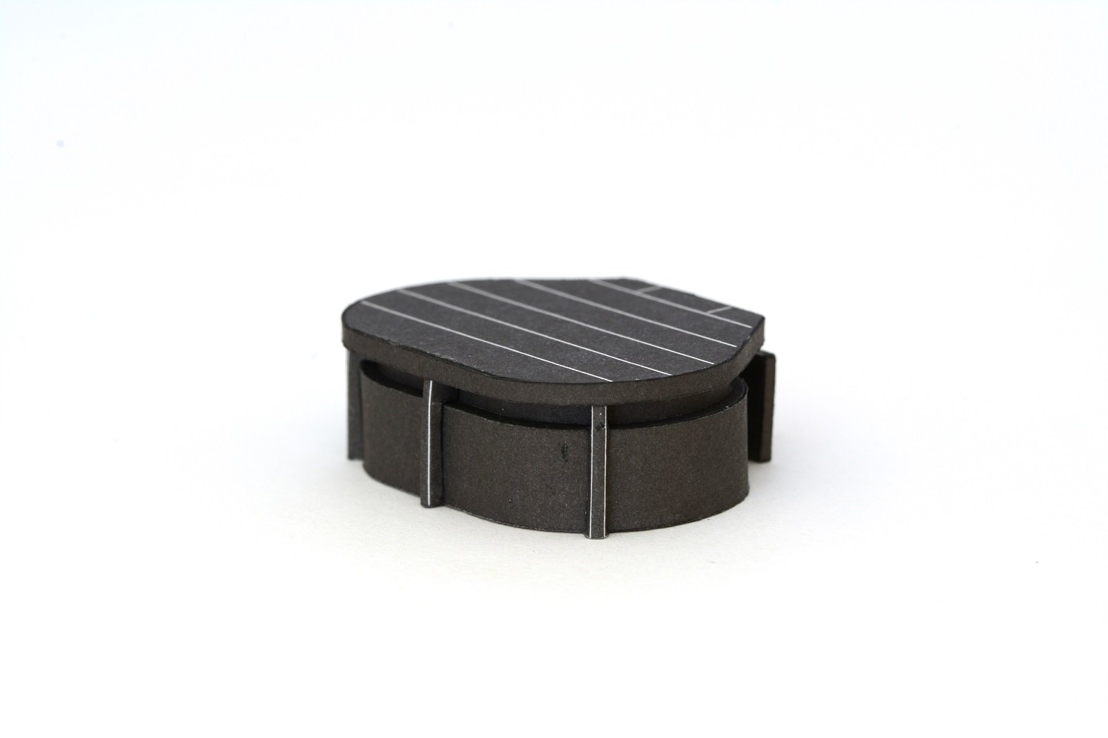
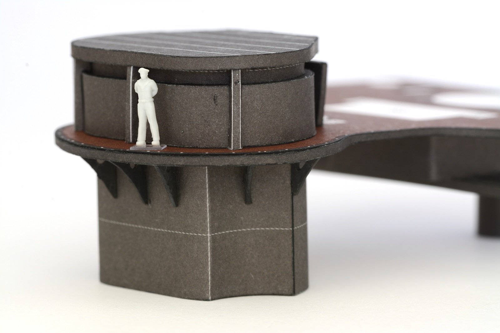
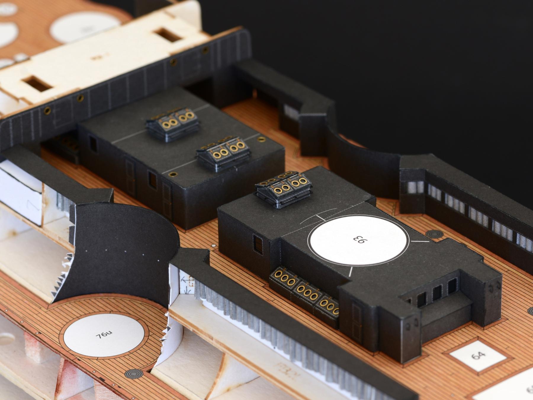
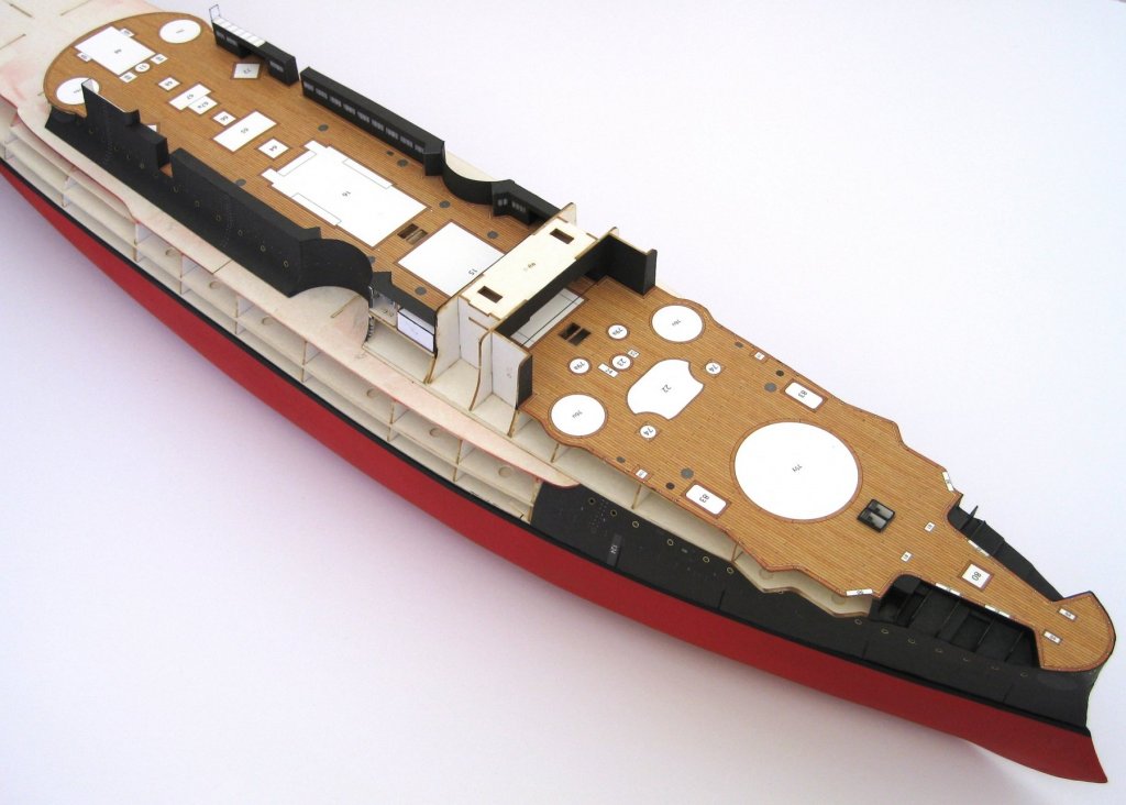
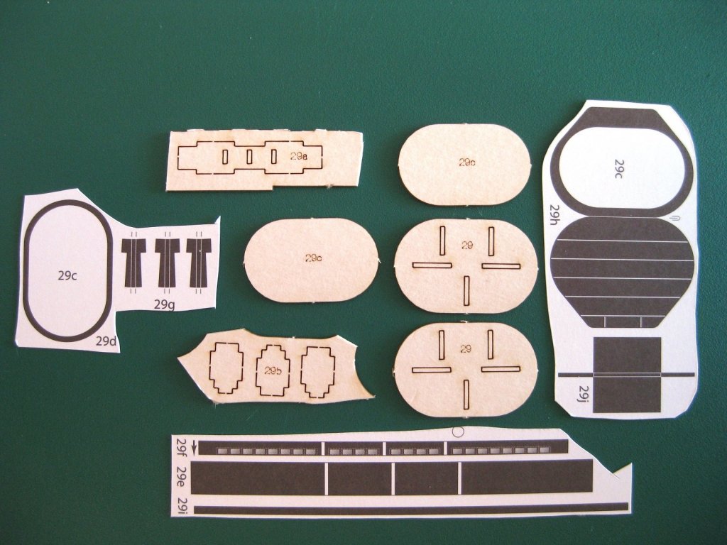
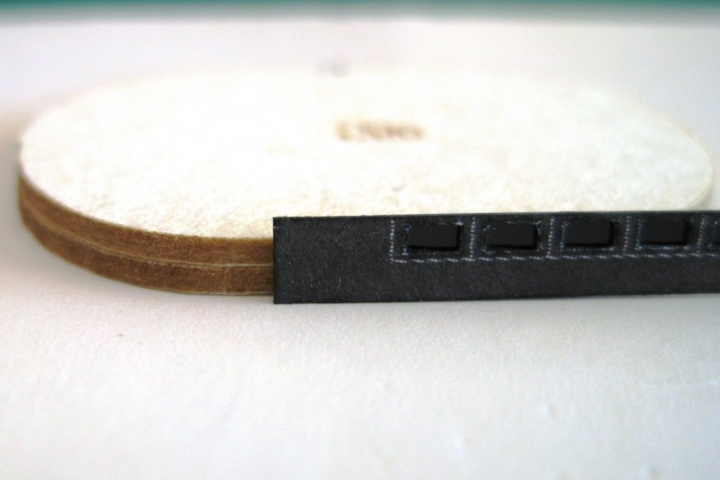
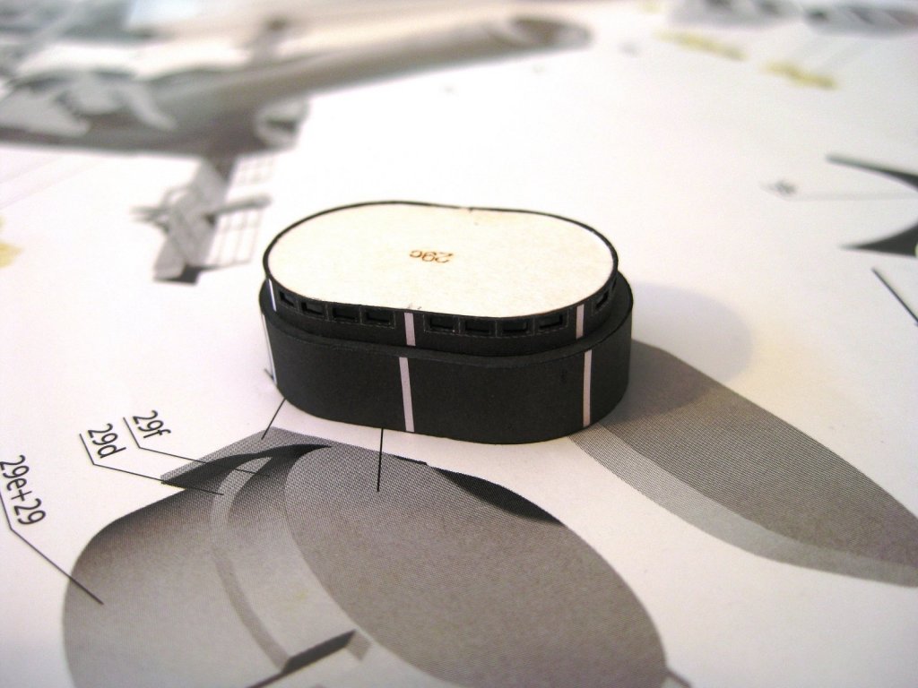
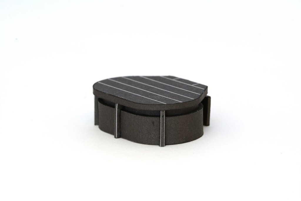
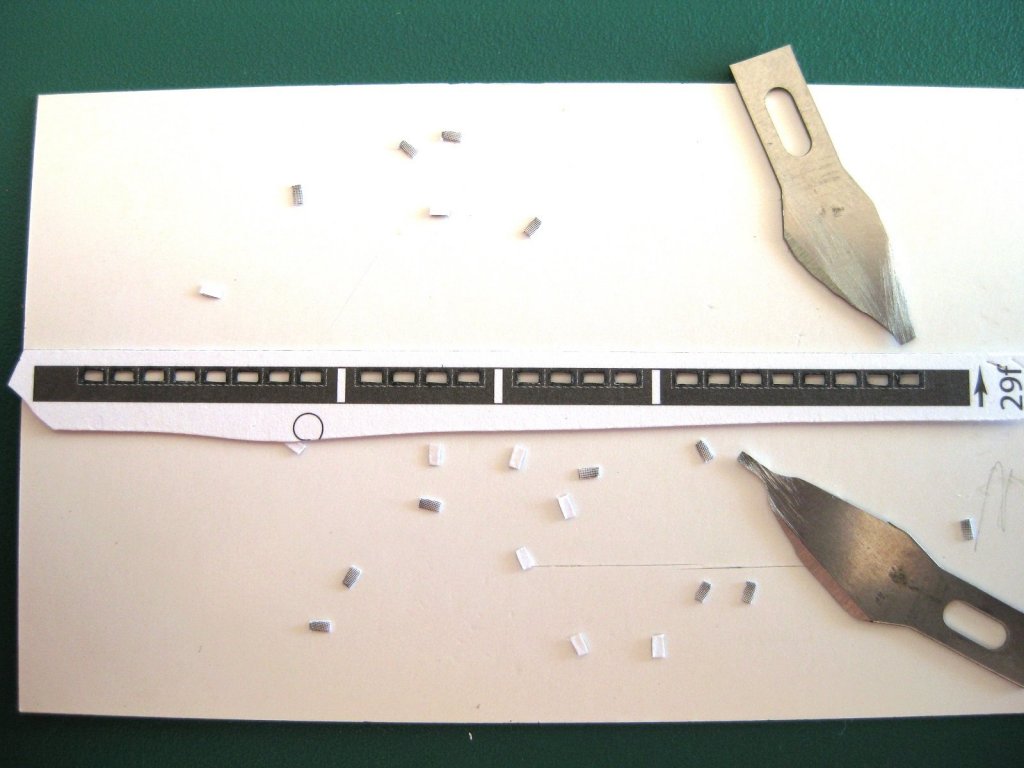
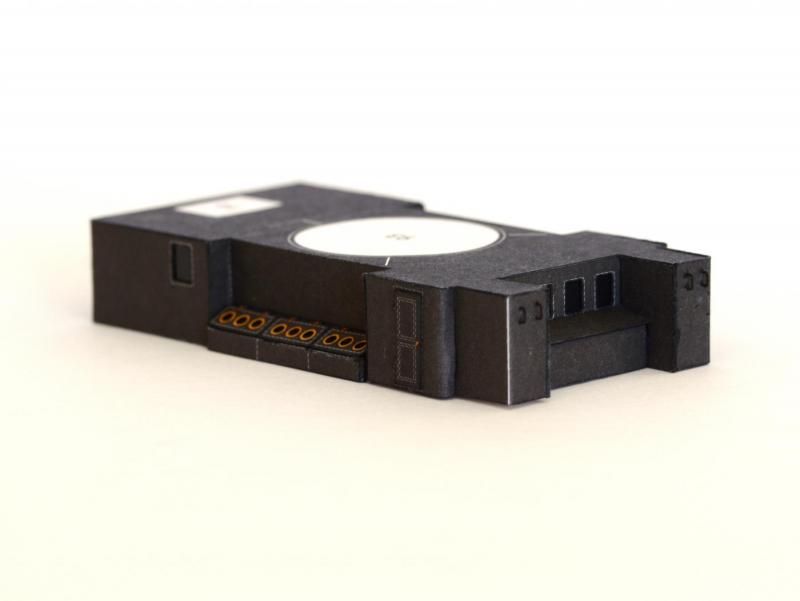
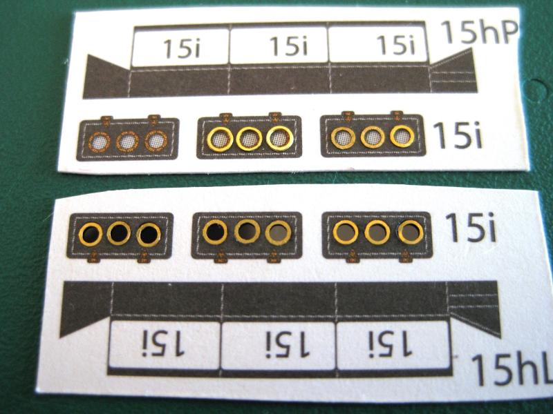
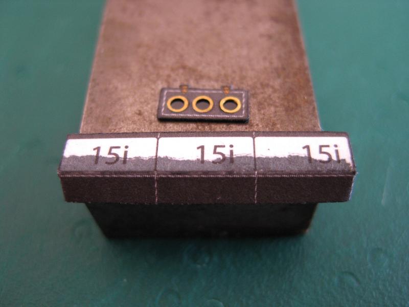
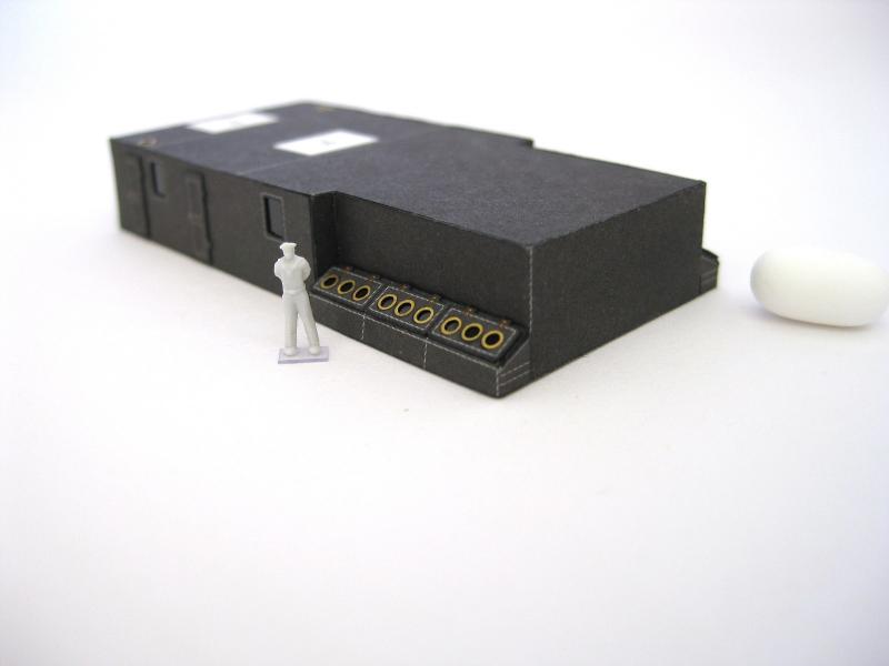
Hi all, continuing on with assembly 29. This is the conning tower and I have been looking forward to doing this one as it builds up into a nice structure. The designer has put a lot of thought into the construction of this part. Typically the conning tower has some of the thickest armour on these ships and I believe for the Borodino it would be in the region of 11” to 13” thick or there about. Rather than wrapping a single skin round a form the structure is built up to give the impression of weight and scale thickness of armour. Of course it does add to the complexity of the part but comes across as a solid object. As usual the required parts all laid out. Looking at the assembly drawing and the parts and numbers it took a bit of thought on how it goes together but once started it becomes obvious and there were no problems encountered. The finished bottom section. I made a couple of mistakes here. The top skin was slightly longer than the form although the width was fine. When gluing the top skin to the form I held it flush with one end before I realised so the other curved end overhung the form. I decided to trim the top skin flush with the form to prevent problems with attaching the side skin but this resulted in the top black border being slightly thin on one end. It is probably only about 0.25mm difference but the eye is drawn to it. (Another lesson learnt) Also the side skin was overly long by about 1mm and despite measuring and marking and double checking I still cut it short. It is not too bad though as the slight gap is at the rear and hidden by what I assume is an armour plate and once the upper sections are attached the border won’t be so obvious. As you can see I still have a lot to learn with this card modelling thing! The strip with the viewports was next and as usual the ‘windows/ports/openings’ were just coloured grey. I thought I would open them up. I am pretty sure in real life they would just be openings with no glazing etc. I removed the ‘viewports’ with my usual method of grinding old blades down to the desired width chisel. I have touched on this in the past but will run through it once more as this is a good example. The blades were ground down to 0.9mm and 1.9mm. As can be seen I haven’t cut the skin to size yet as I wanted to keep as much waste as possible for support of the delicate areas when cutting out the holes. I did the short vertical cuts first starting from one end and doing each cut on one edge before spinning it round and working back down doing the other edges. The longer horizontal cuts were made next doing all the tops and then all the bottoms last allowing the waste to drop out. By following this method the dangerous weak areas i.e. the very thin window tops and vertical bars are fully support during all the cutting out. The edges were coloured using the artist pen from the backside. The edges appear raggedy on the close up after colouring but they look fine with the naked eye. Although the viewports are just openings I will ‘glaze’ behind as usual and did this next to support the very thin window tops and the vertical bars. Once the floppy disc glazing material was glued in oversize I then trimmed the strip to final height so again the thin tops are supported by the mylar. (NOTE THE ARROW on the right hand side of the skin. More on this later!) The viewport skin with the mylar ‘windows’ glued in place and the strip placed next to the top and bottom forms. I don’t know if they expected you to glue the forms to the top and bottom edges of the skins individually but this would be extremely difficult to do successfully. To make it easier I determined that I only need to sandwich a single piece of scrap of the same card the forms came from to make a one piece perfectly aligned form to glue the skin to. I cut the scrap packer slightly undersize all round so the skin is still only glued on the top and bottom edges to the form. Here is the viewport section temporarily placed on the lower section with the viewports to the top as determined by the ARROW in the previous photo. Although not obvious in the photo the white stripes for the additional supports line up nicely. Despite the couple of mistakes mentioned earlier I like how the conning tower is shaping up. Incidentally, if you remember I glued the mylar oversize and it got trimmed along with the viewport skin when the final top cut was made. I didn’t have any problems gluing the mylar to the edge of the card form using the Deluxe Materials Roket card glue. If I remember correctly I think their blurb says it will glue most materials together as long as one of the surfaces is card or paper. Well I can vouch for that. The mylar grabbed to the card form edge right away and after a few seconds pressure I was able to continue working round the perimeter gluing the skin on in stages. The roof section is the last of the major components and as can be seen in the first photo it is a single piece which is folded to give a double thickness roof. I went straight to scoring, folding and gluing the halves together and then cutting to final shape when dry. The last piece of the roof is a strip which is glued round the perimeter, flush with the top and hanging down. This was glued up by placing the roof upside down on a sheet of glass and progressively gluing the strip in stages using a ruler to press the strip home to the roof edge. This turned out a lot better than the same process used to do the perimeter strip on the deck section shown in a previous post, probably because it is wider. The photo shows the part upside. The inside of the perimeter strip was coloured in using the artist pen before gluing to the roof edge. Then it all went pear shaped from here and narrowly avoided, as it turns out, unnecessary damage! To glue the 3 main sections together I determined it would be easier to glue the viewport section to the roof section first so coated the white section as shown in the photo above with glue and flipped the viewport section upside down and after aligning pressed it home for a few seconds. Turning the glued assembly right side up with the viewports to the top I was pretty happy with myself. Hang on; the perimeter strip hanging down totally obscures the viewports…that can’t be right? After checking and double checking the orientation of the arrow I jumped to the conclusion that the arrow orientation is wrong, after all it’s not the first time I have come across mistakes in part numbering. After a moment of panic I reckoned I could get the viewport and roof sections apart (hopefully without damaging either) after all I use glue pretty sparingly and it’s still fresh. So I went at it with a thin blade and after what took an age slowly working it in and prising and going a bit further in each time I finally got them apart without damage and with a massive sign of relief. Right, the diagram shows the viewport and lower section together so the supports can be placed before the roof goes on so placing the viewport section with the viewports ‘correctly’ down on to the lower section it was job done…except the white stripes for the support placement don’t line up?! I was really clutching at straws and at one stage thought I would just colour in the white stripes with black and continue on. Then I thought I would check the viewport position with a 1:200 scale figure, after all he is a scale 6 footer (1800mm) so placed him alongside and the only way he would be able to see out would be to bend his knees. Arrrrgghhhhhhh. So after all that it turns out the arrow was correct, the viewports are at the top, the white stripes align, the crew can see out and the perimeter hanging done obscuring the view is correct. In my defence I still don’t like the viewports being obscured (especially all the work I put into opening them up). I am sure there is a moral to the story here but just not sure what it is LOL With that saga out of the way it just remains to do the 3 supports and the armour plate which turns out isn’t actually attached to the conning tower but sits on the deck behind it. These last parts are just simple scoring and bending so didn’t bother showing them. The 3 supports were tricky though. Here are a couple shots of the finished structure. That’s it for another swing. Cheers Slog


- 244 replies
-
- 14
-
-
- borodino
- dom bumagi
- (and 1 more)
-
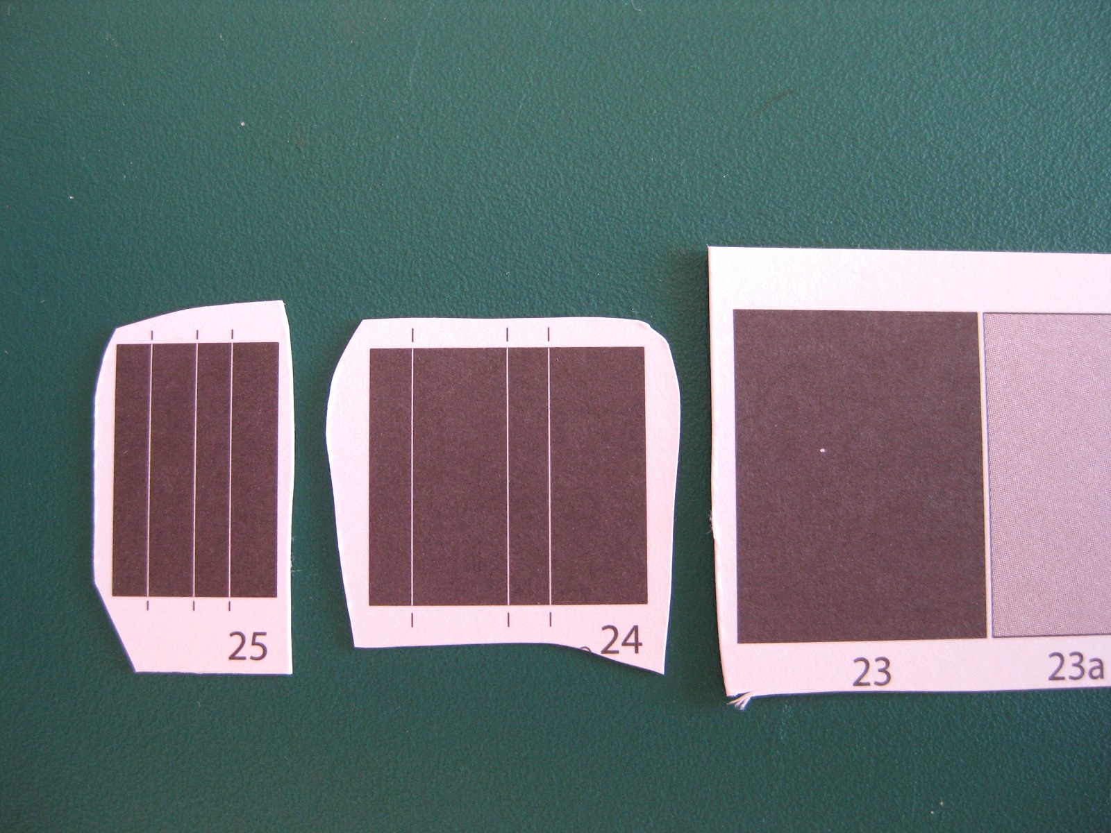
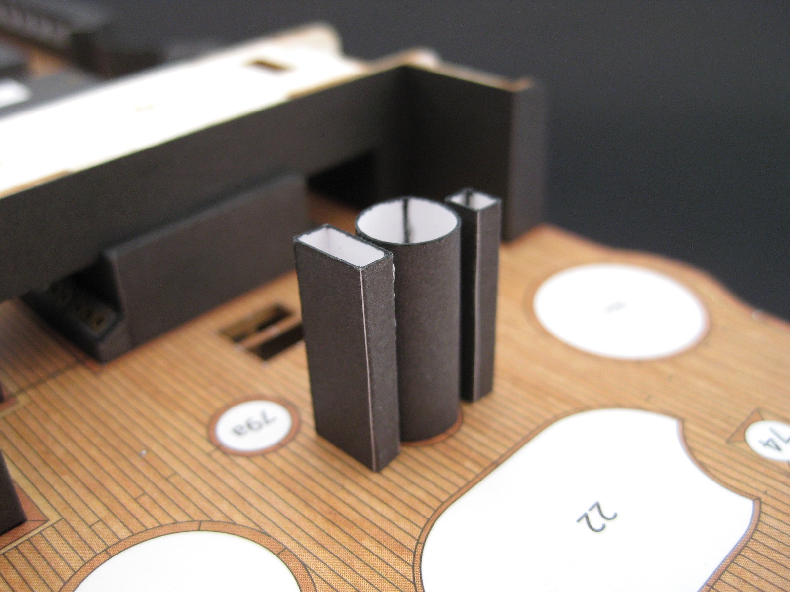
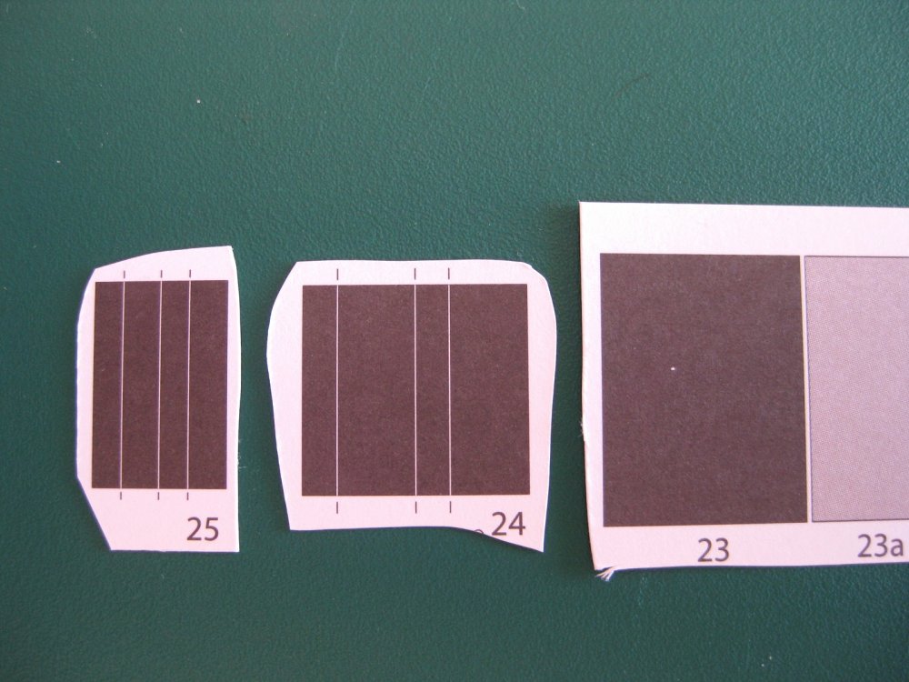
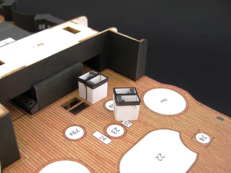
Hi Craig, thanks for the nice comment and to everyone for the likes. In all honesty though I still have a long way to go in modelling in general and card modelling in particular; probably everything I have done to date I have thought it could have been better. Constantly telling myself to remember and do this or don’t do that for the next time LOL. A bit more progress, I had hoped to have done a lot more before making a progress report but unfortunately I can’t get in to the groove plus I wanted to try posting in the new site! Okay parts 23, 24 & 25 are sections of the lower mast and what I can only guess are services trunking/ducts. Surprisingly, particularly for the mast section, these are made separately for each level of deck rather than continuous full length pieces fed down through holes in the decks. I guess both methods of assembly have their pro’s and con’s. The parts are fairly simple requiring rolling for the mast and scoring and bending for the trunking. Unfortunately the trunks didn’t turn out exactly square despite being cut out accurately; I think maybe the bends might have been slightly off giving one side a slightly longer or shorter side throwing the squareness out. I am not too bothered as they are virtually hidden under and behind other structures but more care will be needed for the upper sections. The mast section also had something funny about it in that I cut out, rolled and edge glued the join as shown but the diameter of the finished part is greater than the placement marker it gets fixed to so I will slice the join apart and re-glue with an overlap to match the deck placement circumference marked on the deck. Hopefully I can sit down and get back into the swing of it and do some more before I fly out again. Cheers Slog

- 244 replies
-
- 13
-
-
- borodino
- dom bumagi
- (and 1 more)
-
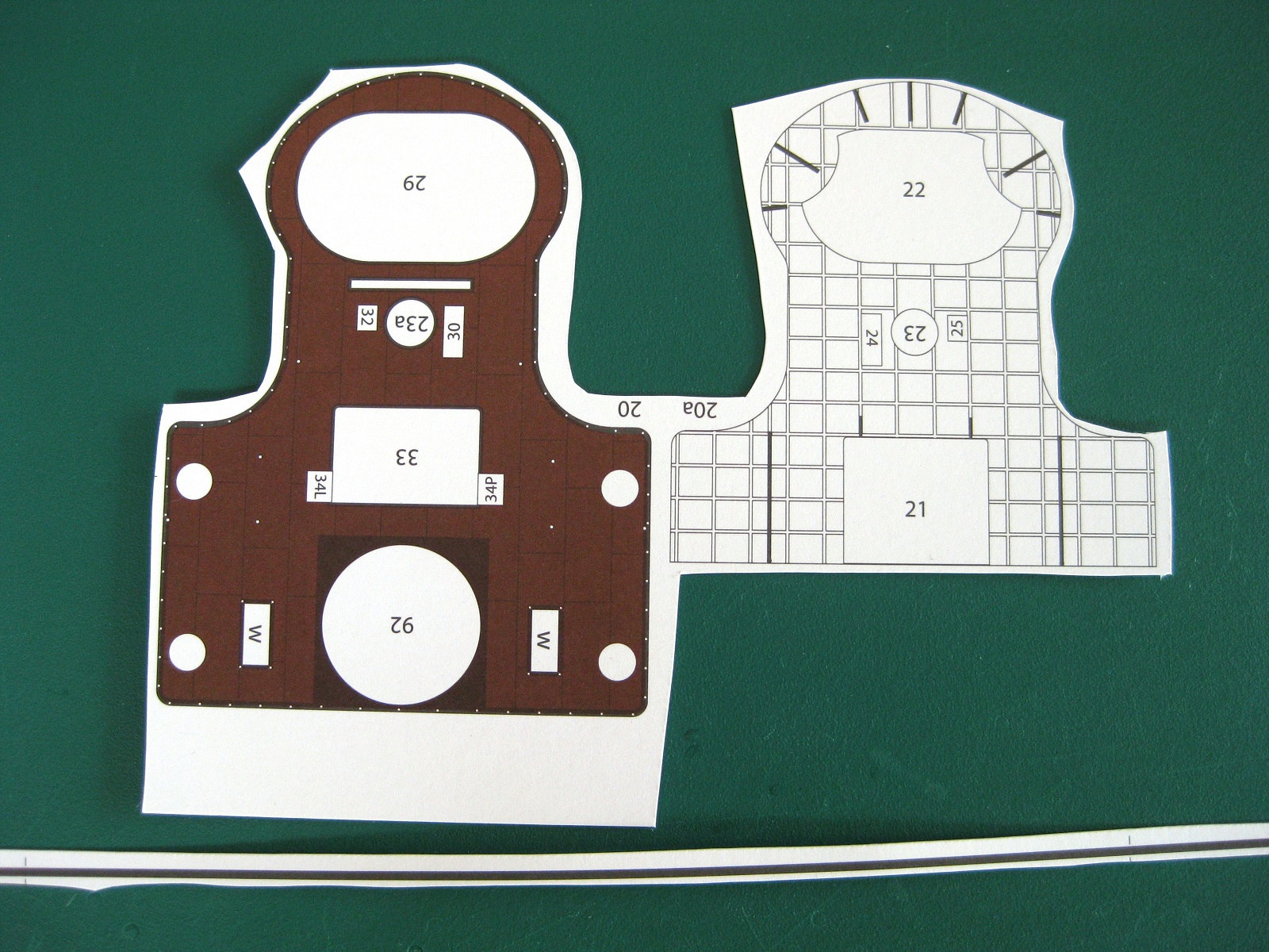
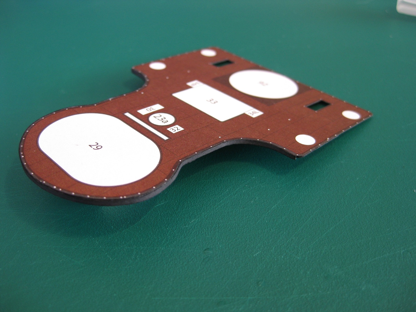
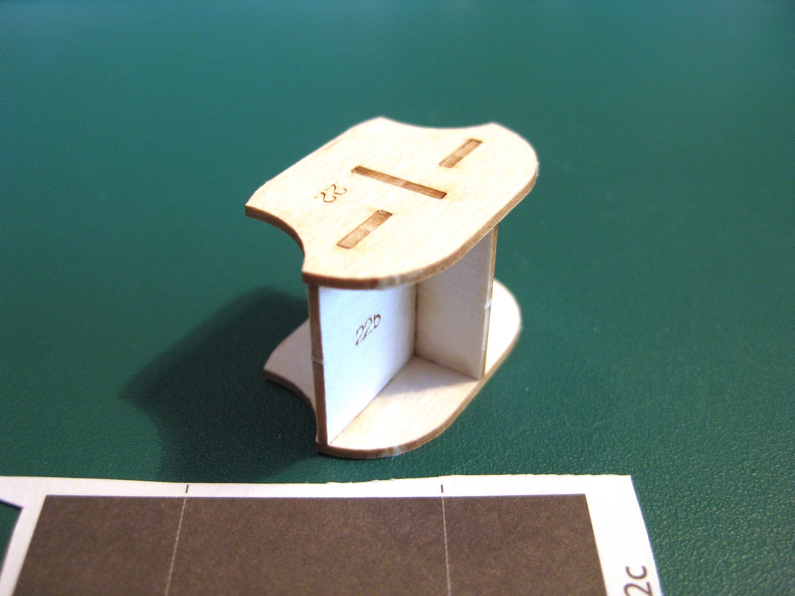
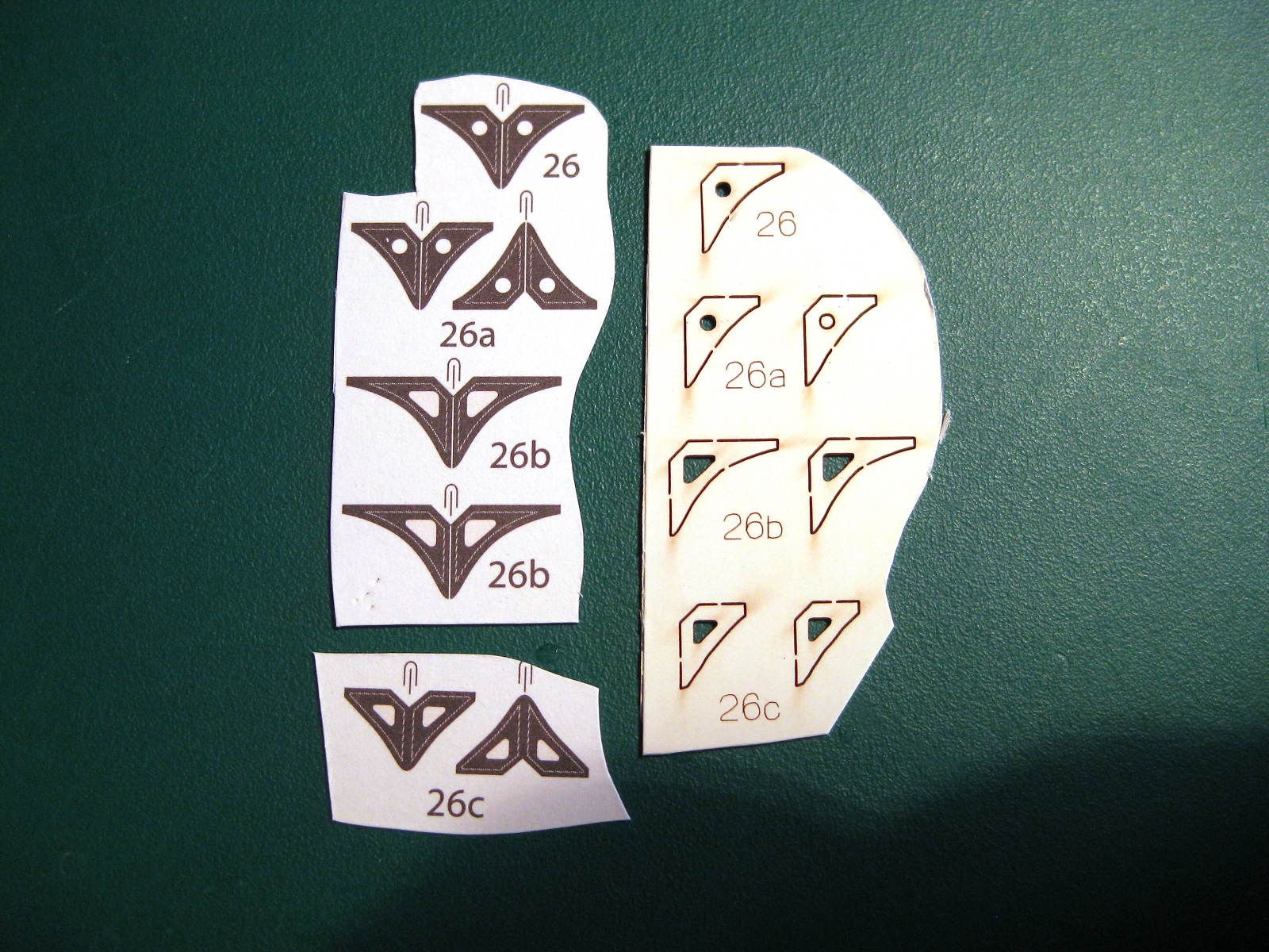
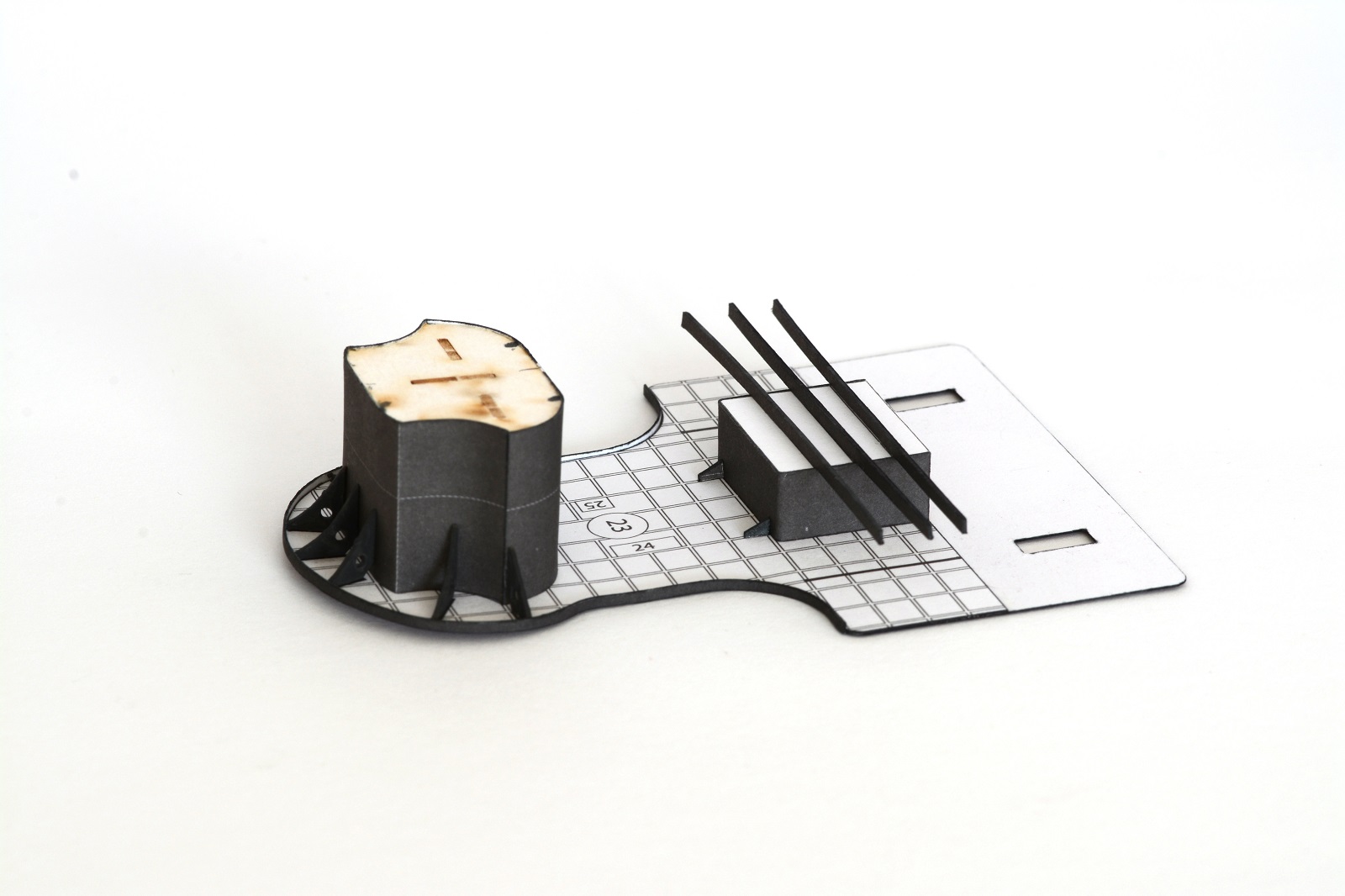
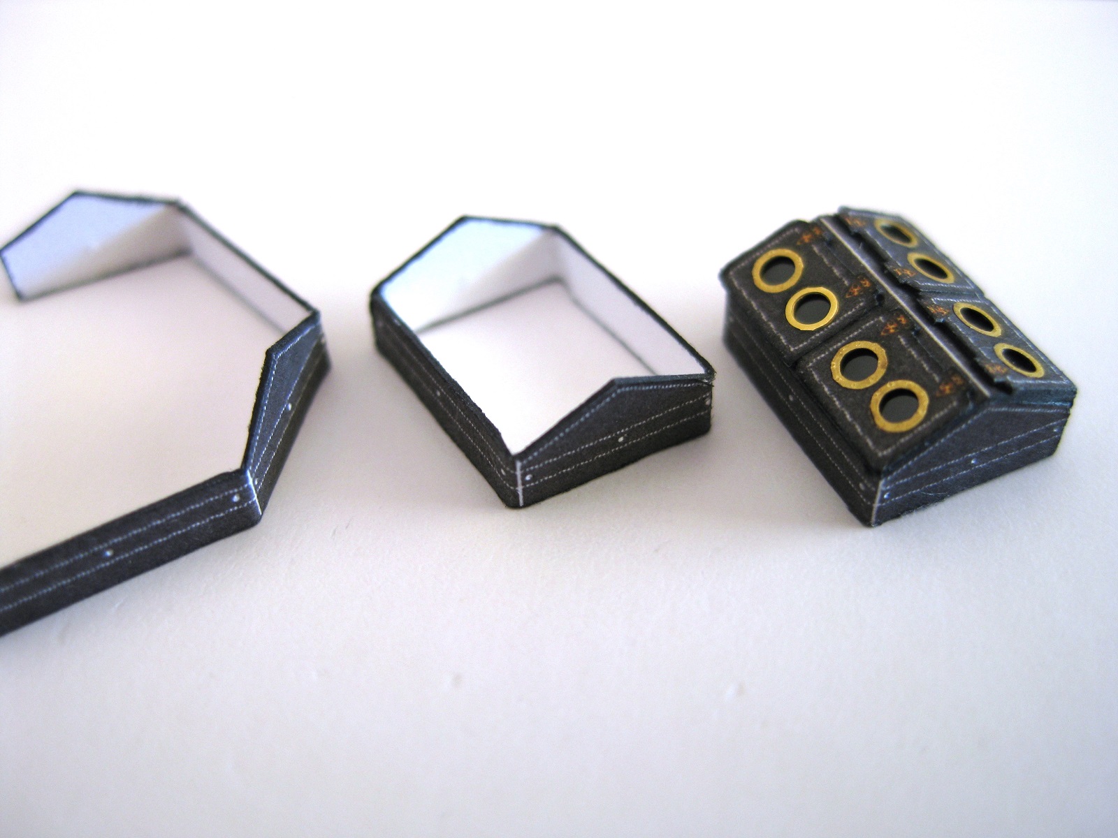
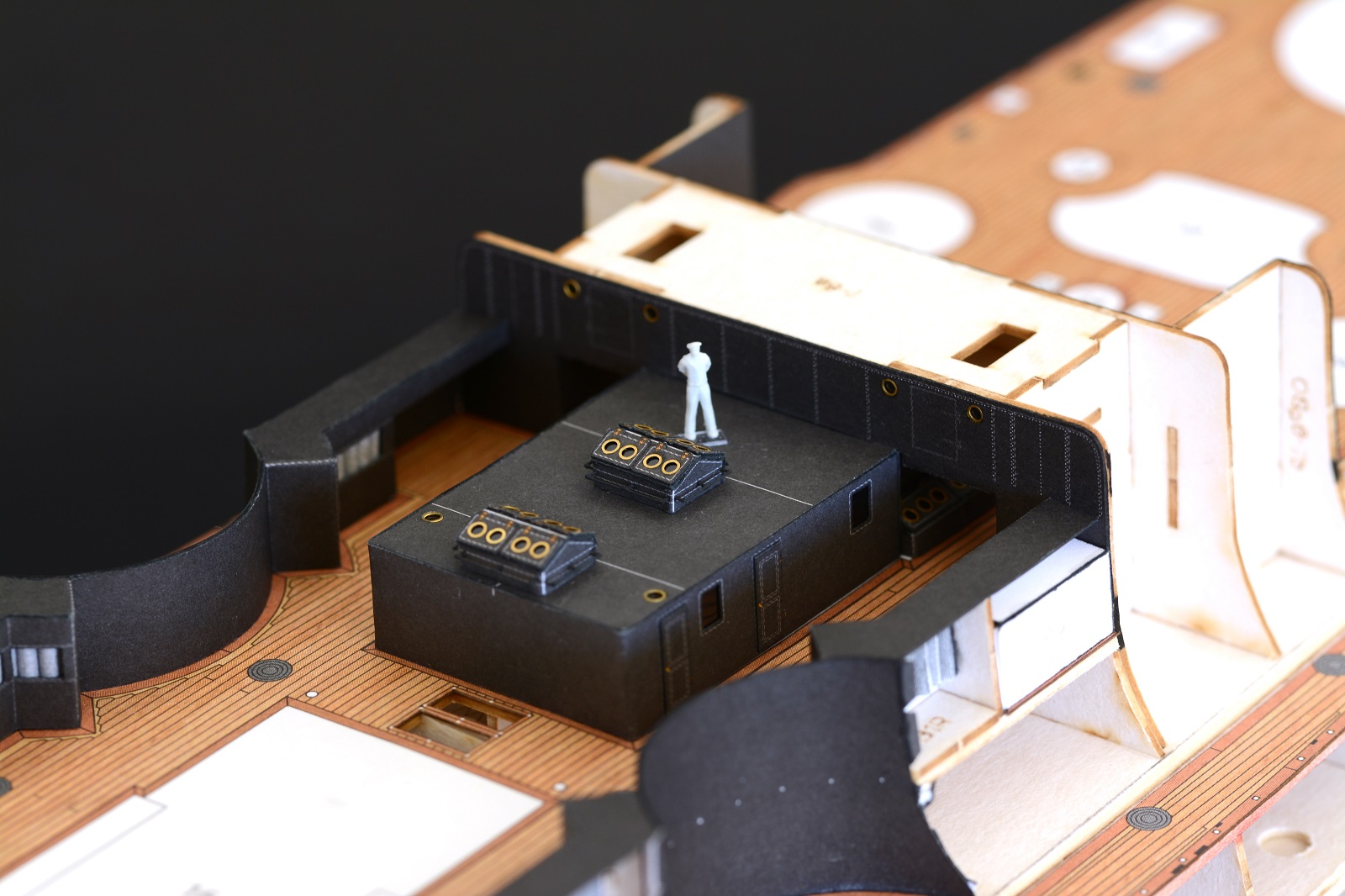
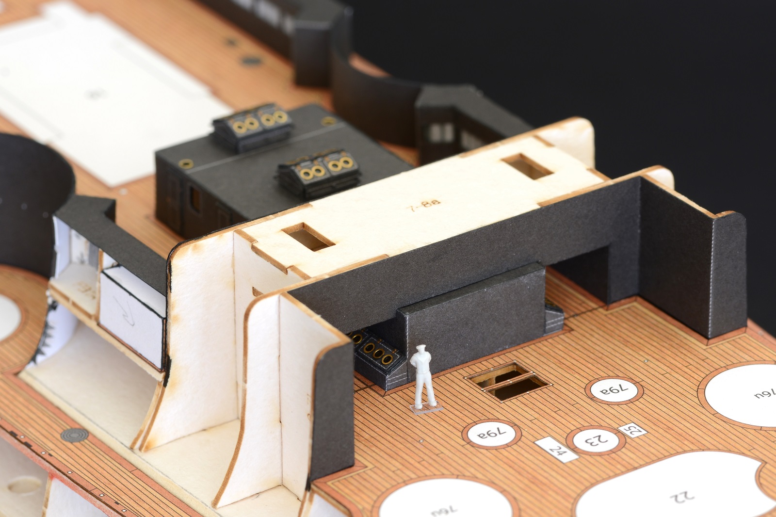
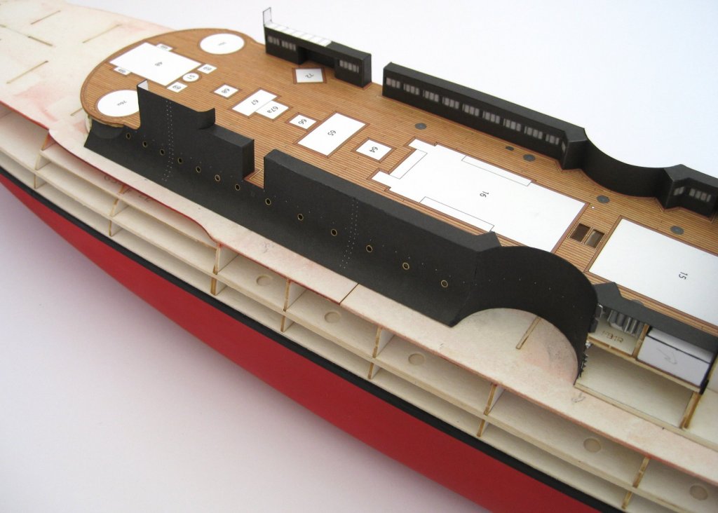
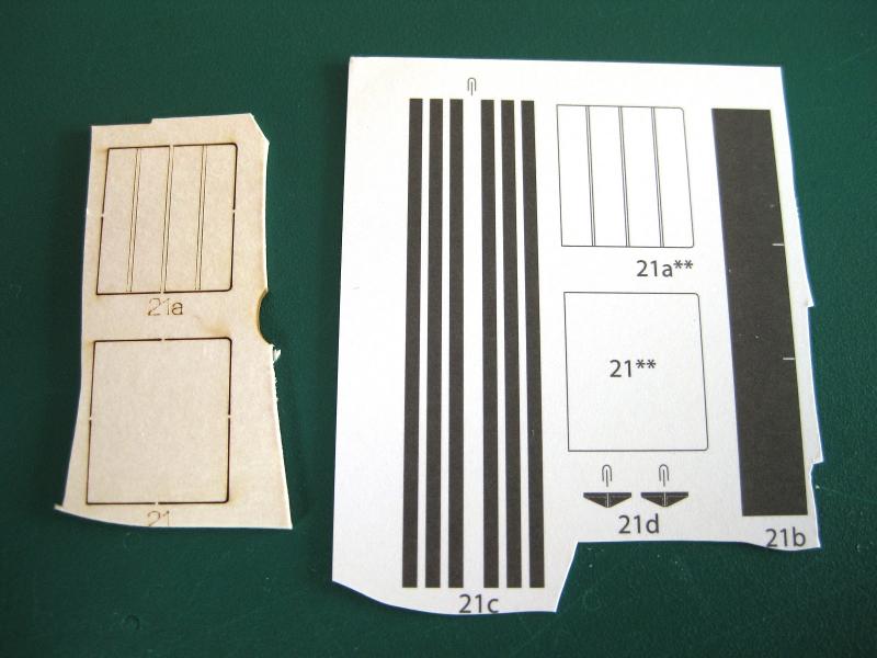
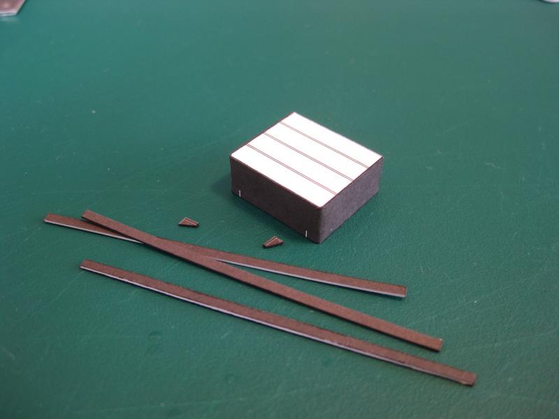
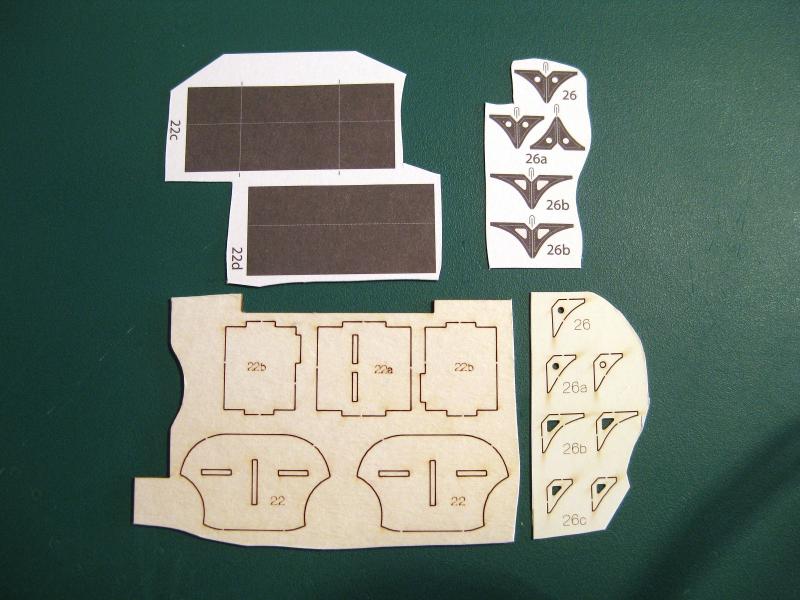
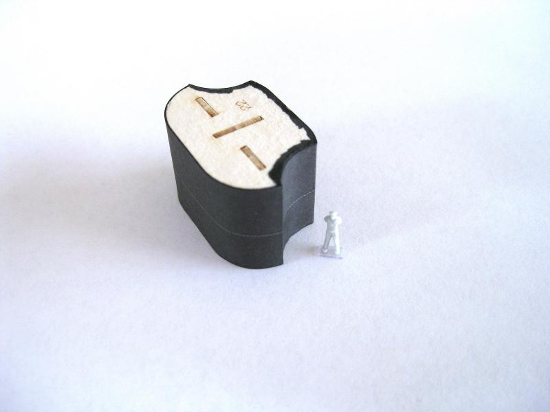
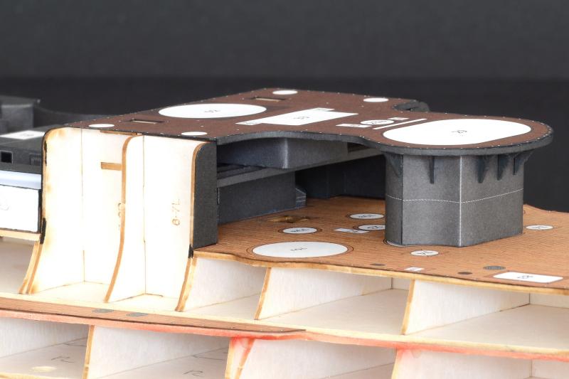
Hi laarmada, thanks for dropping by and the comment and to everyone for the likes. Okay it’s been a while but I finally have an R&R partially to myself to do some modelling. I still haven’t plucked up the courage to attach the upper hull skins I prepared earlier so will continue working through the assemblies in the plan order. Assembly 20 is the conning tower deck which as the photo below shows has very little parts. The photo shows the top and underside of the deck and surprisingly (I double checked) there is no form to be sandwich between the 2 skins. The long strip is a skirting strip which goes around the perimeter but more on this later. There are 2 coamings (part 20c) to go round the openings for the stair wells (W) but not shown as I couldn’t find them! I am sure to stumble across them later but not needed to progress at this stage. To join the top and underside skins together I cut the straight sections first on both parts; noting that the underside skin is shorter as the top skin sits on top of the deck bridge structure and the underside butts against it. With the straight cuts made I had a reference for clamping the 2 parts together in alignment with clothes pegs. Then gently pulling them apart at one end I applied glue with a brush and then pressed the parts together, rolling the knife handle over them. Once left for a bit the process was repeated several times working to the other end and once finished was placed down on a sheet of glass and weighted down and left to dry. The curved sections were then cut out. The plans were vague on the placement of the skirting strip. The plans show the underside of similar decks and shows the strip is flush with the top surface and extends down so this is what I did for this deck. The strip also had 2 bend marks which I can only guess the ends bend back on themselves to double thickness for the rear curve. I decided to chop them to length to single thickness for the complete perimeter. Note the rear section of the deck doesn’t have the skirt as this sits on the bridging structure. Assembly 21 is a box type structure with some beams fixed underneath which I presume are for items to be laid across. The underside skin has the lines printed for the beam placement as does the laser cut form. The side skin only goes on 3 sides of the structure since the back side butts against the bridging structure. All the parts cut out and formed up ready for assembly. With regards to the box structure since only a top and bottom form were provide I measured the height of the skin and used various offcuts of card to achieve the required height so the skin sits flush top and bottom. This was done to ease trying to align the top and bottom forms on the skin edges separately. The beams were scored down the middle and folded against themselves for double paper thickness before cutting out. Part 22 sits between the main deck and the conning tower deck shown above. There are no openings, doors or windows and I believe it is to support the mass of the conning tower above. Not a great deal of parts; 5 pieces of laser cut card to make up the underlying form and 2 skins. The braces (parts 26) will be discussed later. Only point of note is to be mindful of the skin orientation. The white horizontal line is slightly off centre and I determined that the line should be closer to the bottom of the structure due to slight curve to take into account the main deck curvature. The laser cut forms glued up and as usual a perfect fit. I keep saying and will say again the extra cost of the laser cut forms are worth it for ease and accuracy of fitment. The skinning is only as precise and accurate as the underlying form and I believe these have helped my skinning measurably. The finished structure. I attached the front skin first (the one with the 2 concave cut outs). I firstly scored the back side of the sharp bends and preformed the concave curves with the knife handle. Then placing the form upside down on a glass sheet the skin was glued along the flat top and bottom edges and the centre support before offering up to the form and pressing home with a flat ruler. Then each of the concave sections were glued and pressed home with the knife handle. The rear skin was done in a similar manner but only had the 2 convex curves preformed. Returning back to the support brackets the photo shows the paper parts, according to the legend are folded down the middle. This is as per supplied by the kit. The laser cut forms are additions and are from thinner card to the rest of the underlying structures used so far. This gives me 3 options for making the support brackets. I can either use the paper parts by themselves. Glue the skins on to the forms or the quickest and easiest option of just using the laser cut forms by themselves. This was what I did and just painted them with the black watercolours shown in a previous post. The finished deck with the 2 structures glued on to the underside. The deck developed a bit of a bow between the 2 structures but won’t interfere with final glue up. And shown in its place on the deck. This isn’t glued down yet, hence glimpses of white round the base of the front structure and I will need to tweek the rear structure to allow the whole deck to slide back fractionally. The beams can just be seen on the underside. There are still 5 items to be made and fitted in the space between the 2 structures but once the secondary gun turrets are in place little of this area will be seen. That’s it for a couple of weeks. Really thinking about the hull skins being next! Cheers Slog


- 244 replies
-
- 16
-
-
- borodino
- dom bumagi
- (and 1 more)
-
I look forward to following your build also. Greg, I believe Trumpeter are planning on releasing a 1:200 scale Yamato. Cheers Slog
-
Hi Ferit, Good to see you back again. Look forward to picking up where you left off. If the damage is only to the top mast and spar you should up and going again in no time. Cheers Slog
-
If that is the case maybe start putting away some money every month now and when the time comes if you are still short then see if you can incorporate the difference as a Christmas or birthday present. Slightly still on topic; I started to feel guilty as I always seemed to be ordering stuff on-line or disappearing to the hobby store randomly and coming back with various goodies. So came to an agreement with the Admiral that on the 1st of each month I get a cash hobby allowance handout to do with what I like. It is plenty for normal consumables or various hobby hand tools but if necessary I can save it for larger purchases. The beauty is, apart from being guilt free, that there is no questions asked or to be justified when parcels rock up to the door or I return from the shops with a bag of stuff. Perhaps you can settle on a similar agreement with your Admiral. Cheers Slog
-
Most impressive. The production line style of assembly is definitely the way to go once the process is refined. Looking forward to more.
-
Intro to Card Models Pt. IV: Tools & Other Supplies
Captain Slog replied to ccoyle's topic in Card and Paper Models
Card Modelling Cutting Tools I Use I thought I would expand on the basic craft knife used for card modelling and discuss the different cutting tools/alternatives I regularly use and the reasoning why I use them (or not). 1. Swann Morton Scalpel with No.11 Blade: I have only been using these for a short time but have been impressed with them so far. The biggest benefit and this may just be me, but I find I can more easily and consistently cut the edges of the paper square which was an issue for me previously; and for that reason alone means they are now my primary cutting tool. I think it’s because they aren’t so pointed so that I can see the ground surface of the blade easier for aligning perpendicular to the straight edge. The less pointy tip does have disadvantages for me though, which will be made clear in 2a below. A couple of advantages I have heard are that they are sharper than the No.11 craft knife equivalent. There is no doubt a new blade is extremely sharp but I can’t say for sure that they are sharper. I have also heard that they remain sharper for longer; for me personally I haven’t found this to be the case and if anything may dull quicker than the equivalent. This may be a perception thing and will reassess after I have used them extensively. I have heard of people disliking this handle due to the narrow hard edged nature of it. I only find it uncomfortable if I am applying lots of pressure but then if that’s the case then it probably isn’t the right tool for the job so usually have no discomfort with the handle. 2a. Typical Exacto Type Handle with No.11 Blade: Firstly all my blades including No.11’s has been the Excel brand. This was what I used exclusively until recently but still use regularly for a number of reasons. The blades are deeper and pointier compared to the Swann Morton’s. I use the pointier tip for making small ‘sewing machine’ type pin pricks to cut out small tight curves and the deeper blade is useful for making pivoting, rotating cuts I use for convex curves. I also find the pointier tip easier for doing freehand curved cuts as I can follow the cutting line better. The biggest disadvantage of this blade for me personally is I find it difficult to consistently cut square edges for the opposite reason the Swann Morton allows me to. I now have both the Swann Morton and the Excel knives side by side on the cutting mat when modelling and alternate between the two depending on the cutting task. 2b. Shaped/Ground Down No.11 Blade: I keep all worn blades which I then use a Dremel on to grind them first to a specific width and then to put a chisel type cutting edge on them. They are used to cut vertically down through the paper. These are made to specific square or rectangular holes requiring cutting out in the paper part and I may grind 2 or more different widths to suit each hole. I personally find cutting small holes this way better than using the normal straight edge and slicing cut giving cleaner sharper corners. Of course this works better for smaller holes and larger holes with longer straight edges can be cut using the normal method. Incidentally No.17 blades are already chisel shaped so these only need grinding to width and resharpening if worn. 2c. Curved Blade: I don’t use these for cutting paper/card but use them for cutting photo-etch parts free from the frets. I place the fret on an old/blank CD or DVD and use the blade by pressing down to make the cut. The curve allows the blade to be rocked for particularly tough cuts. The curve also allows more blade edge to be in contact with the fret rather than the tiny point of a No.11 blade. I have only recently started using a curved blade for photo-etch and much prefer it now over the No.11 previously used. There are smaller curved blades available which I need to source for ease of use on tightly packed photo-etch frets but the concept is the same. I have heard of others who use curved blades for doing free hand paper cuts as apparently it allows them to smoothly follow the cut line and change direction if I remember correctly. I haven’t used a curved blade for free-hand work so can’t comment on the accuracy of this. 3. 9mm Retractable Snap-off Knife: I use these almost exclusively for rough cutting out of parts from the parts sheets instead of using more expensive No.11 blades which are saved for final cuts. These snap-off blades are very cost effective as the handle is loaded up with several strips each containing a number of blade segments. As the blade wears it is snapped off to reveal a new sharp segment. Once a strip of segments has been exhausted, pulling the thumb catch fully rearwards engages a new strip. I prefer the Stanley brand as the blades are very sharp. I also use them for cutting off-cuts from thicker card for packers, cutting balsa, paring wood and just general cutting, again to save wasting No.11 blades. I have heard of card modellers who use these for final cutting of parts as they are very sharp and as mentioned very cost effective. I personally don’t use them for final cutting of parts as I have found that if the blade isn’t held exactly perpendicular to the part it can wrinkle the cut edge slightly and for me it is too hit or miss. Although I guess if I gained more experience using them for final cutting, consistency would be achieved. I also find the handles too big and clumsy for critical cuts and being left handed the blade exits from the handle on the wrong side to see the edge comfortably and fingers holding down the straight edge can get in the way of the bulky handle. If you are right handed, then this may be an alternative to the No.11. Alternatively, smaller, thinner handles which only hold one strip of blades are available and this would eliminate the bulky handle issue but I haven’t tried these as my current handle is sufficient for what I use it for. 4. Single Edge Razor Blade: Another useful blade which gets regular use. It is perfect for slipping into the kerf on laser cut forms for slicing the little nibs to free the part. The part then only requires a couple of swipes with a sanding block to remove the remains of the nib for a clean fuss free part. I also use these regularly for folding paper parts similar to the method used for photo-etch; sliding the blade under the part to the fold line and rotating the blade up to form the fold. My favourite brand for these were Stanley which came in little plastic boxes of 10. Since my local hardware store stopped stocking these by Stanley I have tried many different brands (all identical in size and shaped) but none have the sharpness the Stanley ones had. 5. Stanley Knife (utility knife): I used to use this mainly for cutting out forms from thick 2mm card when I had to glue the part templates to the card. Since I now use laser cut forms whenever possible this knife has been relegated to more abusive forms of use such as cutting brass tube and bending and prying off kit book staples etc. I also use it for hacking and chopping clothes pegs for clamping and cutting thick bits of balsa and wood for packers etc. Very useful for sharpening pencils and slicing through blister packs. 6. Scissors: I have never used scissors for cutting out paper parts. I do use them for cutting other thin materials such as floppy disks for windows etc (knives cause a ridge to form on the floppy disc material). Other than this they see very little use. For making straight cuts nothing beats a knife and straight edge. They may be useful for making curved cuts but depending on the radius or the part shape access may be an issue without bending the part. Again I have heard of modellers using scissors but I have never tried it so can’t comment further. 7. Circle Cutters: These are invaluable for cutting circles (as the name suggests!) such as wheels from paper. If you build vehicles, then they are worth getting a set and I suggest paying a bit more for a decent brand. A branded set also allows for spare blades to be readily available at a reasonable cost although they usually come supplied with 5 or so spare blades. The generic circle cutter in the photo (blue & yellow) was a disgrace; all the supplied blades had burrs on them from the manufacturing stamping process and tore the paper. I was able to file and clean them up and put a honed edge on them which was time consuming and frustrating but they did cut nicely afterwards. The adjustment tightening screw did need to be really tight to prevent the set diameter changing in use. The Olfa cutter (black & yellow) was twice the price but being Japanese the blades were sharp out of the box and much more enjoyable to use as well as readily available spare blades. It was necessary to make sure the adjustment knob was tightened but not to the gorilla grip necessary for the generic cutter. I also suggest spending a considerable amount of time cutting out circles from scrap until you get a feel for it and determine the best method for using it to prevent destroying your model parts. I got the best most accurate cuts by going round and round gently until the part was cut through. (all parts were laminated on to 0.5mm to 1mm card). If you try and force it to cut too deeply at once the blade will wander particularly if cutting thicker materials. Summary: Well that’s all the card modelling cutting tools I use at one stage or another on a build and how I use them. Certainly a knife handle and some No.11 blades are all you need to get you started with card modelling but as shown I use alternatives for pretty specific tasks, which is mostly to reserve the No.11’s to final cutting only. Remember this is what works (or not) for me and your mileage may vary. Cheers Slog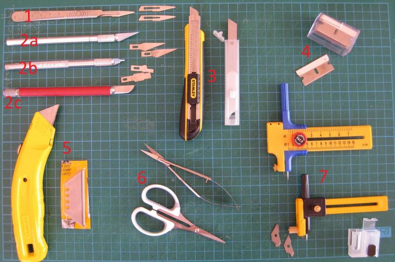
-
Hi Carl, Been following from the beginning and home again so I can finally post using a real keypad. Looking forward to following your log and your turrets look fantastic. I am interested to know what glue you used to fit the large sheets of brass to the plastic turret tops. Cheers Slog
-
Hi Chris, It looks like the Bismarck in what I believe is the Baltic colour scheme. There are a number of build logs of the Bismarck in the kit build log section of the forum. Cheers Slog
-
Another stunning piece of work Greg. Photo-etch is such a game changer nowadays. Models just keep getting better and better; of course it still comes down to the modellers skill to obtain such results. Cheers Slog
-
Beautiful work. Can't wait to see the final product. Cheers Slog
- 339 replies
-
- 3
-
-
- dumas
- Chris-Craft
- (and 3 more)
-
Hi Owen, Great progress so far; I look forward to following your build. I agree about the laser cut forms, they are worth their weight in gold!! I have used a few different ones now and they always fitted perfectly. They are such a great time saver and set you up with a nice accurate hull to move forward with. Cheers Slog
-
Hi Sam, you are right about the silver solder. I have 'easy' which is the lower temperature one but still high compared to the electrical or plumbers solders. I did try some electrical rosin core solder but it didn't like the torch which is all I have at the moment. The plan is to get some solid plumbers solder and an iron and experiment with a few different combinations of solders and heating. Cheers Slog
- 244 replies
-
- 4
-
-
- borodino
- dom bumagi
- (and 1 more)
-
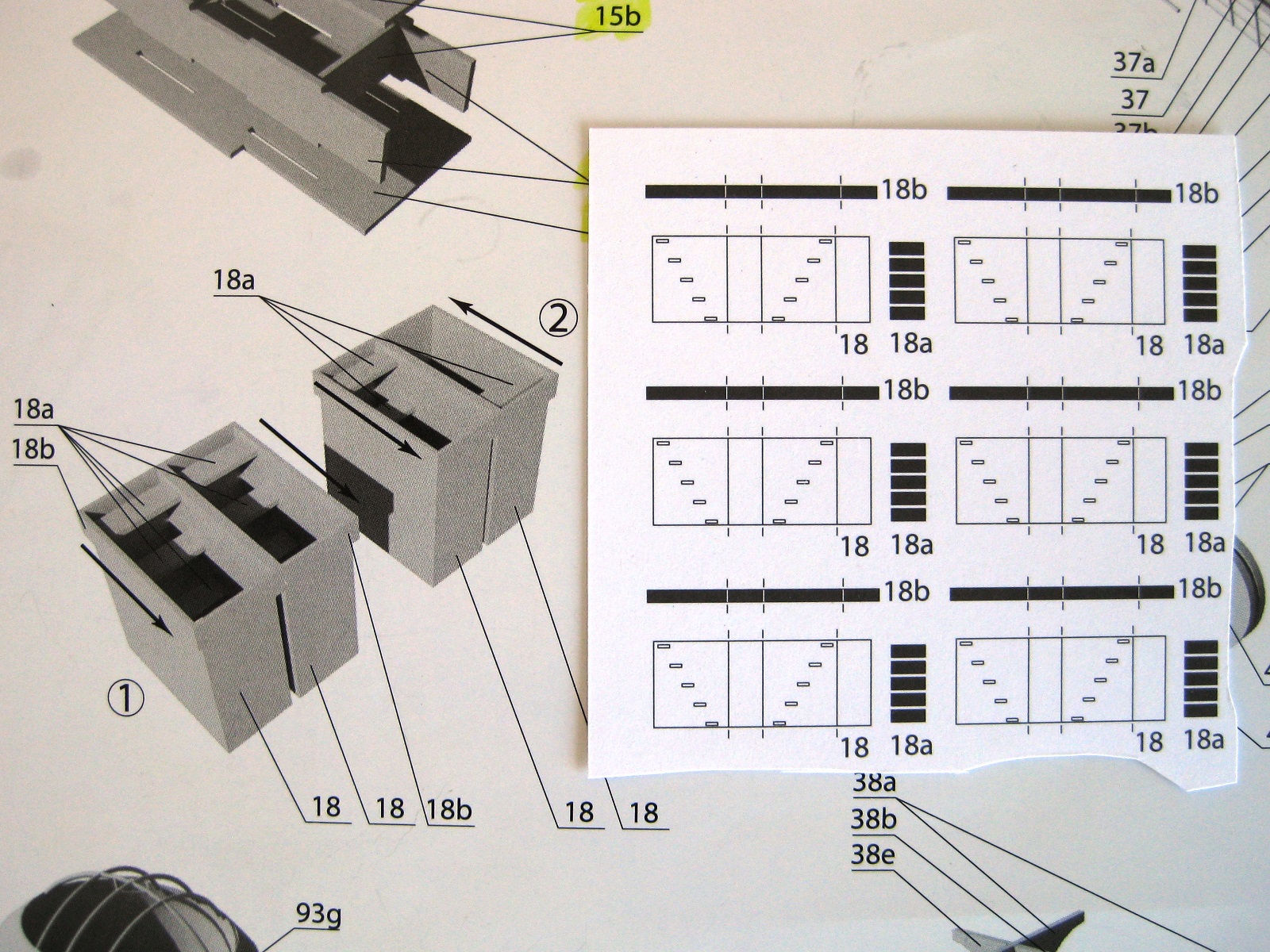
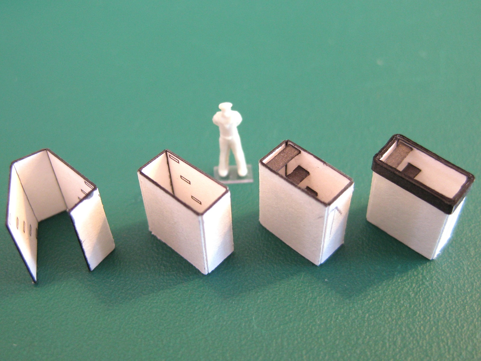
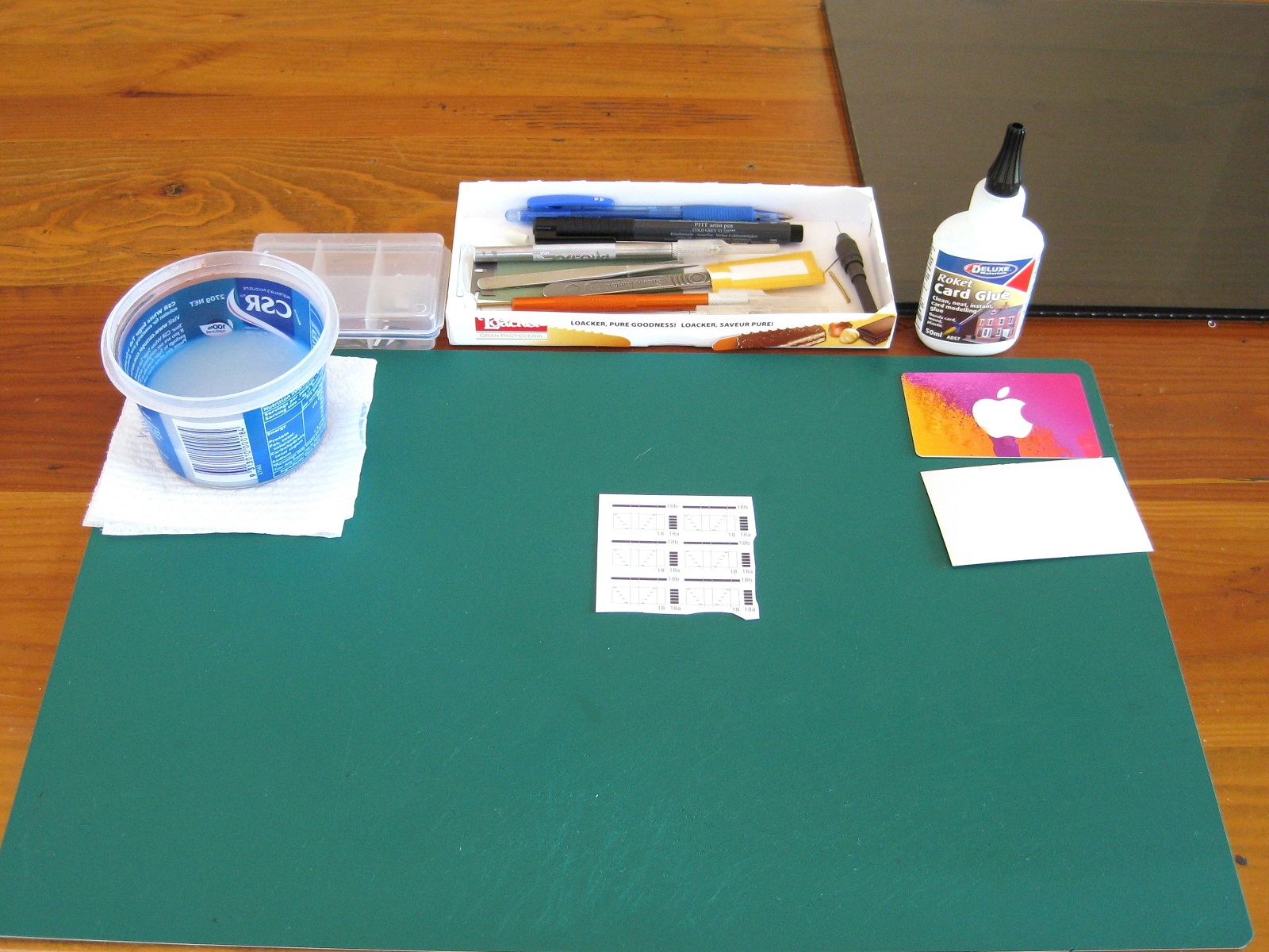
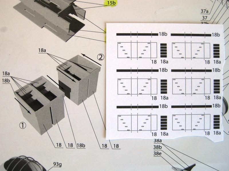
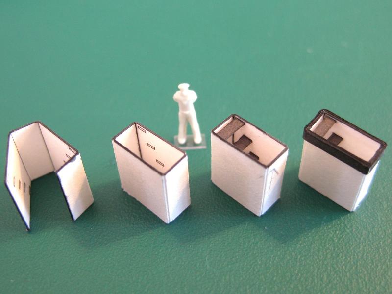
Hi All, I have just been idling along the past day or so messing about and drifting in and out of the ship yard to pick and poke at things. Grant (gjdale) got me thinking about soldering again so had a play around with what I had and after a few tries I can (almost) reliably solder the 0.2mm brass wire using silver solder paste and the gas torch. Moving on. Since I just finished assembly 16 I will keep with the flow and do assembly 17…Have I mentioned just how vague card model plans and instructions are? I did? Good because no matter how much I searched the assembly diagrams I could not find hide nor hair of 17! I know there must be because I remember freeing up a small square hatch when cutting out other parts. A search of the parts sheets finally yielded the necessary parts, all 2 of them. Assembly 17 builds into a small square tube with the aforementioned hatch on top and they are labelled 17L & 17P (left and right). Okay I can understand not showing a simple folded tube with an end but at least tell me where they will reside. There is no point doing these yet because until I stumble across their final location I won’t know the orientation of the hatch. Oh well, assembly 18 here we come, at least they have a big diagram showing them to be stairwells and they even show that they have 2 configurations; 1 both going in the same direction and 2 going in opposite directions…and that’s it. They don’t tell what configuration goes where. I know that I previously cut out 3 pairs of holes in the deck when it came time to fix that down so there is that and I can just make out from another diagram that configuration 1 is the foremost holes in the deck so guess configuration 2 go to the other 2 holes, which makes sense as these are turned 90 degrees to the long axis. Saying that, they will be near impossible to see once all the other assemblies go over the tops of them. Here are the steps (pun intended) taken from left to right. Firstly they were cut out to size and the bend lines transferred to the outside and scored quite heavily to get a sharp bend. The part was held down face up and ruler pressed hard on the fold line and a razor blade slid under and folded up. I started from one end and worked along so I could do all the bends with the wide ruler. The open ends were edge glued and pressed together to close the box. For some reason I don’t know myself I didn’t glue all the treads to one side before closing the box and then gluing the other ends of the treads once closed up. I must have thought the next step would be easier…it was certainly longer! The treads were placed in and glued one at a time starting from the top and working down. Once I had a tread in place poking and pushing it with tweezers and needles I used a small paint brush to come up from the bottom and place a spot of glue to the underside of the tread. Once the treads were in place it was just the combing to place round the top. Not sure if my treads bulged the stairwells a bit or for some other reason but the combing strips were a bit short. After cutting to width and trimming one end I thought I better check it against the box for size and luckily was able to leave one side of the combing over long to trim back once the circumference was glued up. All other combings, were left overly long on both ends for ease. Just a close up of the treads. From the 6 individual stairwells a couple weren’t the best but as mentioned apart from the 2 on the foredeck most will be barely visible if at all. The configuration 1 stairwells in place on the foredeck. I will need to double check the diagram to make sure they are pointing in the correct direction. Something which suggests these are slightly oversize can be seen by looking at the deck planking. At the front of the combing can be seen a darker deck plank with white dots (for a frame for the weather canvas) well the darker plank with more dots should be down the sides of the combing also but I had to sand until the stairwells dropped in. Also my careful cutting of the openings on the deck away back near the beginning of the log was unwarranted as I had to remove the centre bar also. Not a big deal as I will just adjust the framework size so it still sits against the outside of the combing. Overall pretty happy with them. The other 2 pairs of stairwells in Configuration 2 shown next to one of the other locations. The centre bar in the deck will be removed as per the previous photo. The last location is actually between structure 15 and 16 which in real life would be awkward trying to cut across from one side of the deck to the other. Both these other locations require framework for canvas covering as can be seen by all the white dots. Lastly just included this photo to point out a couple of things I do/use. Despite having a dedicated modelling room to myself it still hasn’t been furnished/setup so I am still working on the end of the kitchen table. When I am working I bring out more and more tools and bits and pieces from the toolbox and eventually the cutting mat is covered with crap and I can’t find the right knife or tweezers or bit of brass for punching etc. Well the other day after polishing off some chocolate biscuits I looked at the box and thought if I cut off the lid it would be perfect for laying the tools in when working keeping the mat clear. So now I grab the knife etc from the box and place it back across the top ready for next use. Unfortunately after a modelling session all the tools get cleared off back in to the toolbox. Also in the photo at top right is a sheet of glass. I use this for gluing up components as it is smooth and very flat so with this as a base I can keep flat things flat also using it as a base and placing a square on it I can get exact 90 degree corners etc. Glue doesn’t readily stick to it also so if a part has some overspill I can lift the part off the glass without it sticking and getting damaged and the glass cleans up very neatly. I never cut on the glass except masking tape where I can stick a length of masking tape down to the glass and then using a ruler and knife trim whatever width of tape I need or to clean up a tape edge for masking. The tape then peels easily off the glass for use. Even if you don’t card model I suggest getting a sheet of glass as it is a great addition for modelling. Geez it looks like I like the sound of my own typing!!! That’s it for this swing. Cheers Slog


- 244 replies
-
- 11
-
-
- borodino
- dom bumagi
- (and 1 more)
-
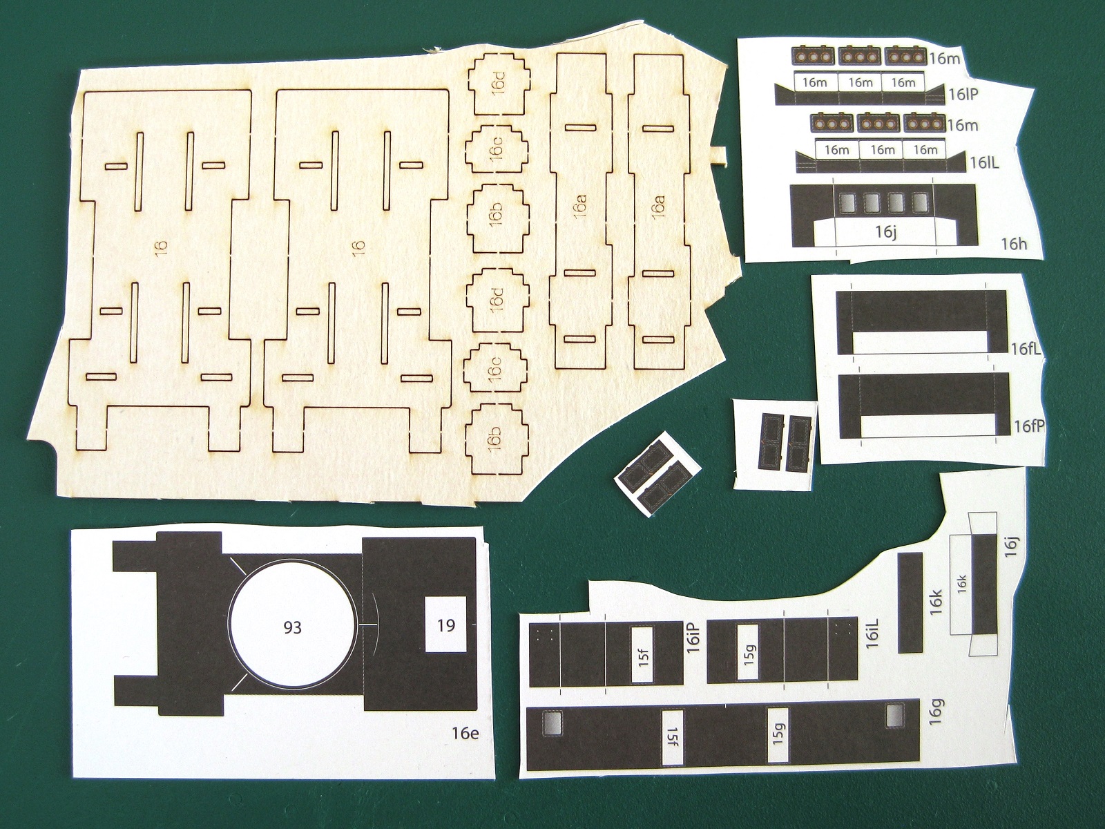
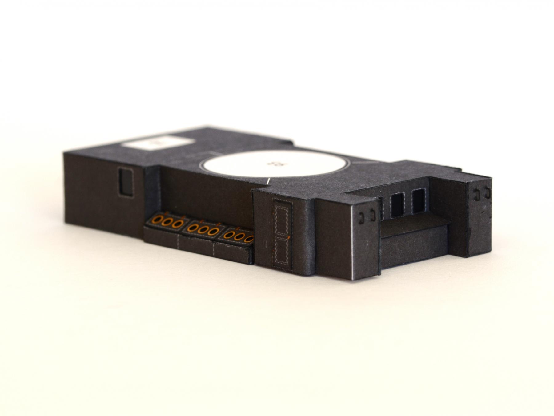
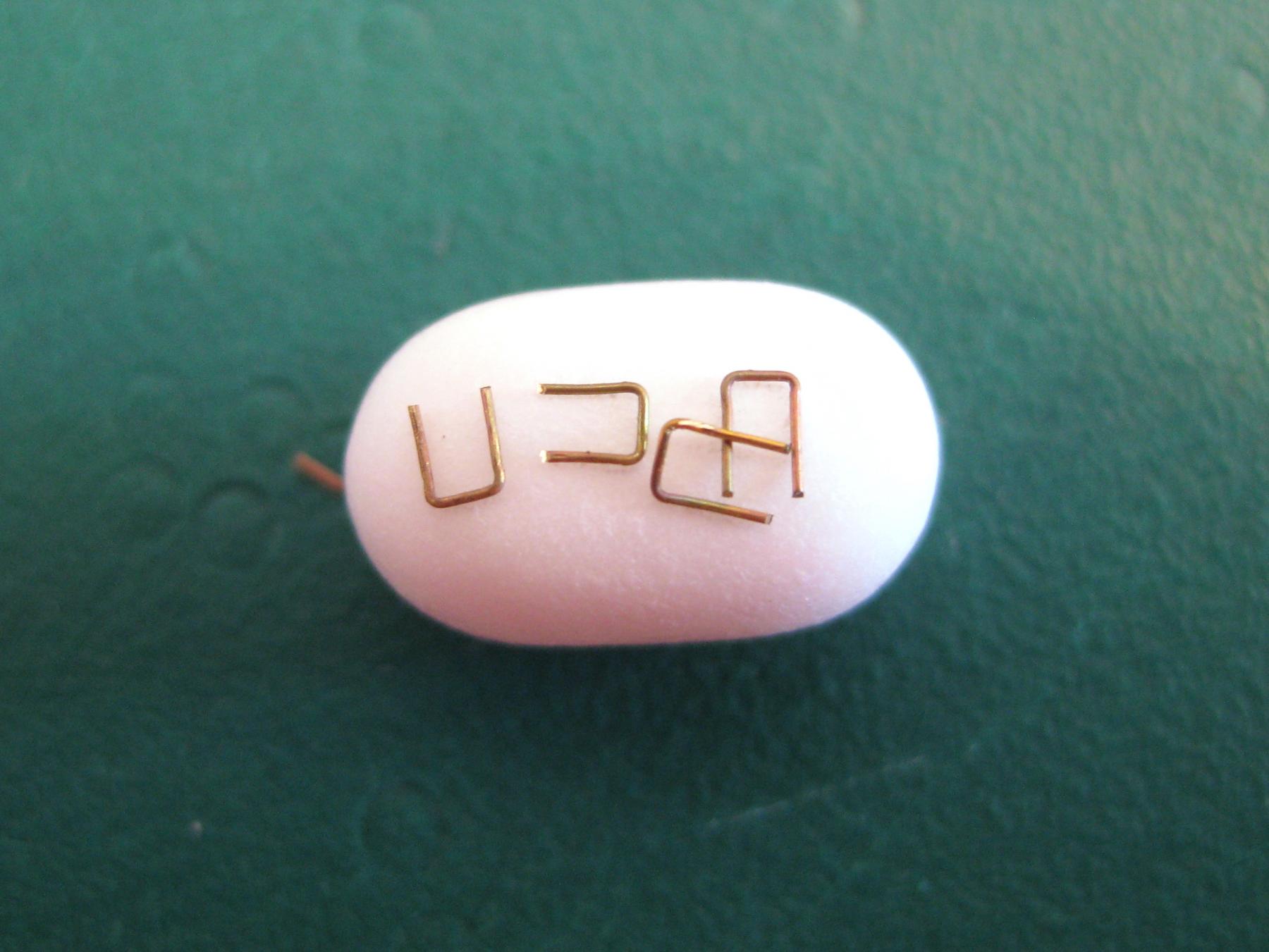
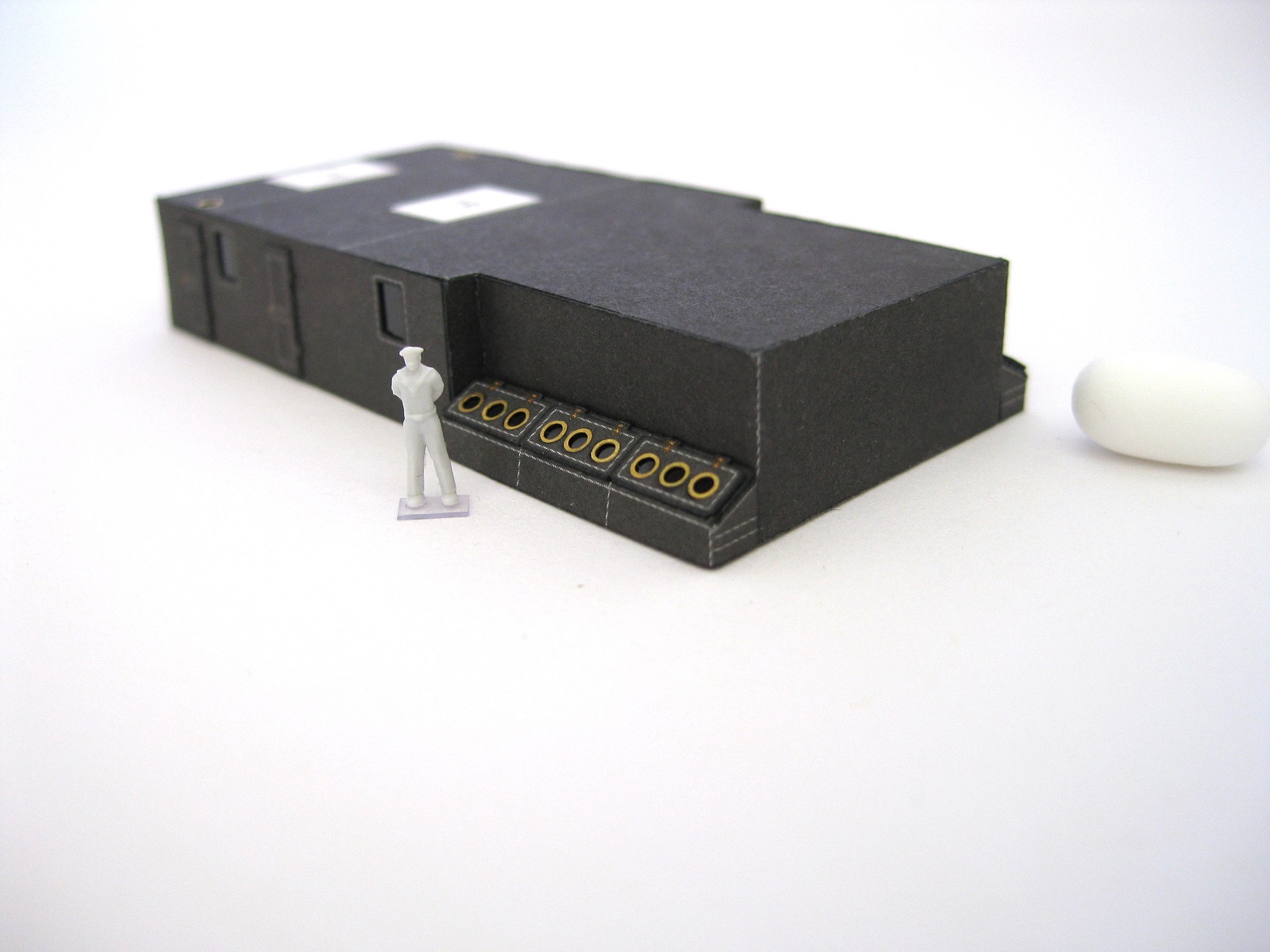
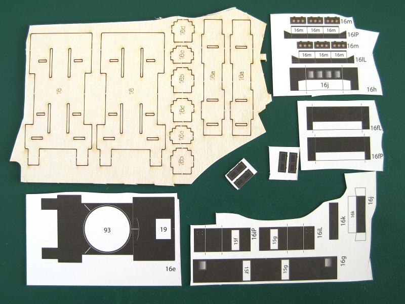
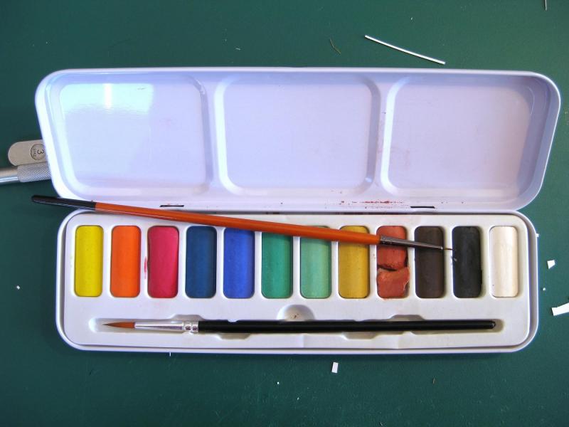
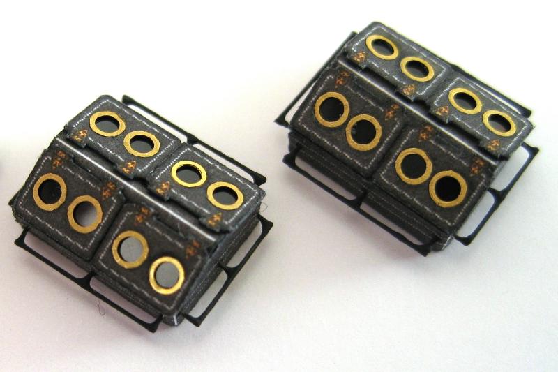
Thanks for all the nice comments guys and everyone for the likes. Grant I have thought about soldering but don’t have a soldering iron at the moment. I have had a play around previously with the soldering torch but remembering the wire is only 0.2mm in diameter it was difficult to heat it up without destroying it! Too gentle approach to save the wire affected the silver solder paste as it didn’t really get up to temperature. There was a couple of times where it just flashed the wire enough not to destroy it but enough to get the silver solder paste to flow but the window of opportunity is very small. I also tried using rosin core solder but it didn’t like the torch at all. The plan is to get a soldering iron and some solid solder and a flux paste/fluid and play around again. The problem comes down to holding the wire in place as it is so small just touch it wrong with the tweezers and it ejects itself across the room. For a different project making up a grill with 0.5mm wire which I can easily silver solder I tried taping down all the pieces but of course it burned off with the torch and I guess the fumes contaminated the joints as the silver solder failed to hold. I will certainly try playing around when I get a soldering iron. Incidentally I could have done the handrails by bending the 2 outer supports from the handrail and would only need to worry about the centre stub which doesn’t need to be a strong joint as the handrail and 2 outer stubs would be one piece and self-supporting. Hindsight is a wonderful thing LOL Okay next bit of progress is structure 16 and all the parts are shown below. I haven’t gone into much detail as the construction is essentially the same as the previous structure 15 posted earlier. It was a bit more complicated due to all the ins and outs and I am not as happy with how it turned out compared to assembly 15. Several of the side skins were over length and needed to be trimmed considerably to fit; also I ended up cutting instead of folding some parts to make fitment easier. Here is a photo of the completed structure; doors? check, portholes? check, windows? check. The only different items on this structure are the addition of some handles on the end. I did double check to make sure these are vertical and not the expected horizontal of step irons! My first fabrication of step irons (or handles in this case). These are 0.2mm diameter wire which I annealed using the soldering torch as this brass just snaps if you try to do too tight of a bend otherwise. I checked the distance between the pin pricked holes with the digital callipers and then went around measuring everything I could think of to match the width. It turns out two 6” steel rules gripped together was perfect. The rulers were pressed down on to the wire and the legs folded up and then given a squeeze with tweezers. The over long legs were trimmed back a bit with nail clippers. The legs were fed into the pin pricked holes and a 0.5mm drill bit was placed in the hoop and the step iron pressed home for a consistent distance. Here is the cheapo water colours I used to paint the iron work. It goes on so much easier to the tiny wires than brush painting Tamiya paint and dries to a more complementary black also. You can also use this type of paints for edge colouring but at the moment the PITT pens are easier and more convenient for me. Final shot of it in its spot. I have also temporally placed the 3rd of the 3 skylights, which were made previously. I only have 3 more days before I fly out again so will continue working on the sub-assemblies. Cheers Slog


- 244 replies
-
- 16
-
-
- borodino
- dom bumagi
- (and 1 more)
-
Great stuff Grant, you are certainly well set up for creating these parts. Look forward to seeing the finished article. Cheers Slog
- 339 replies
-
- 3
-
-
- dumas
- Chris-Craft
- (and 3 more)
-
Byrnes Drawplate
Captain Slog replied to Landlocked123's topic in Modeling tools and Workshop Equipment
Thanks for the explanation and photo; I wondered what the curved handle was for. You learn something new here everyday. Cheers Slog -
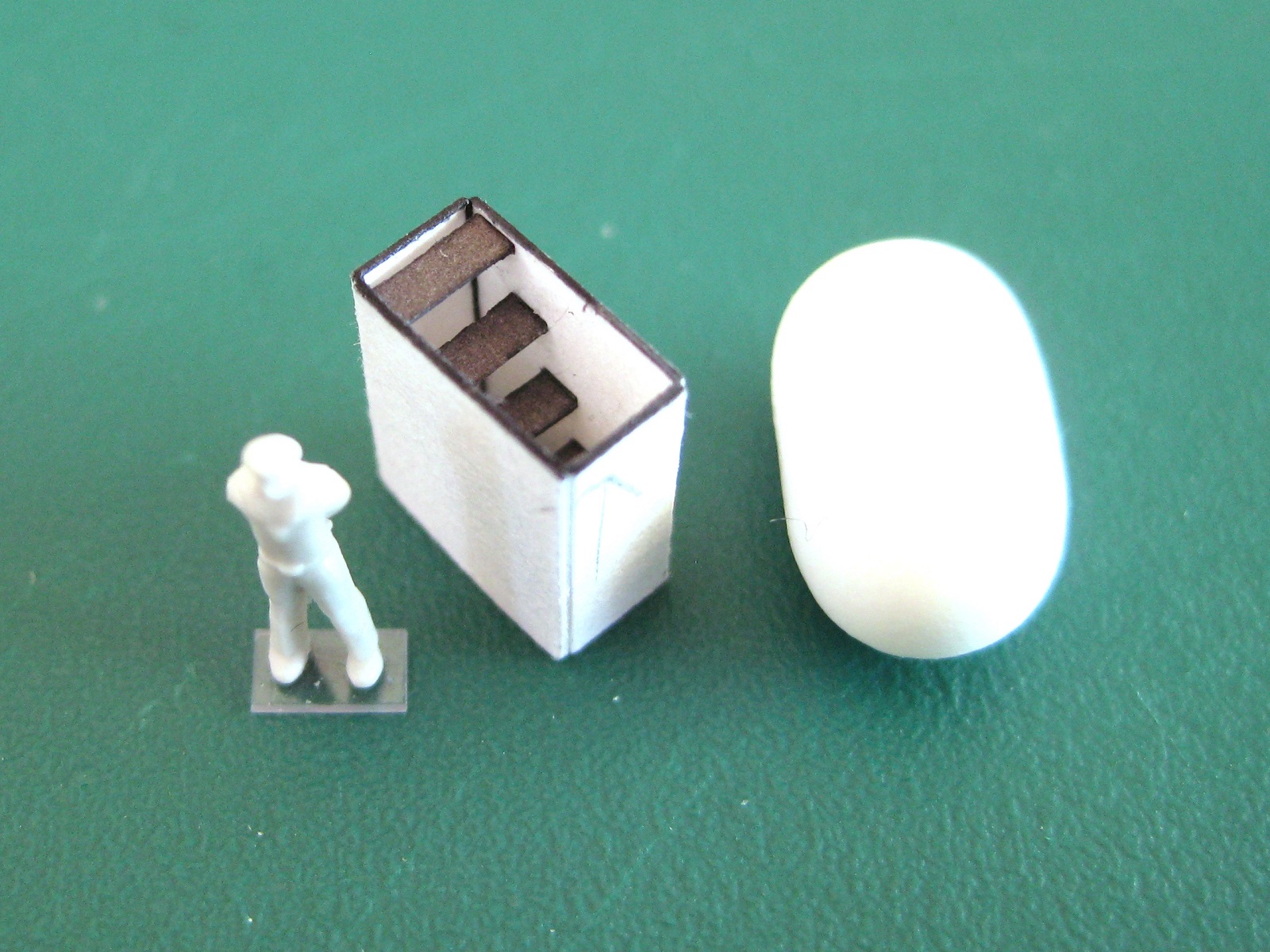
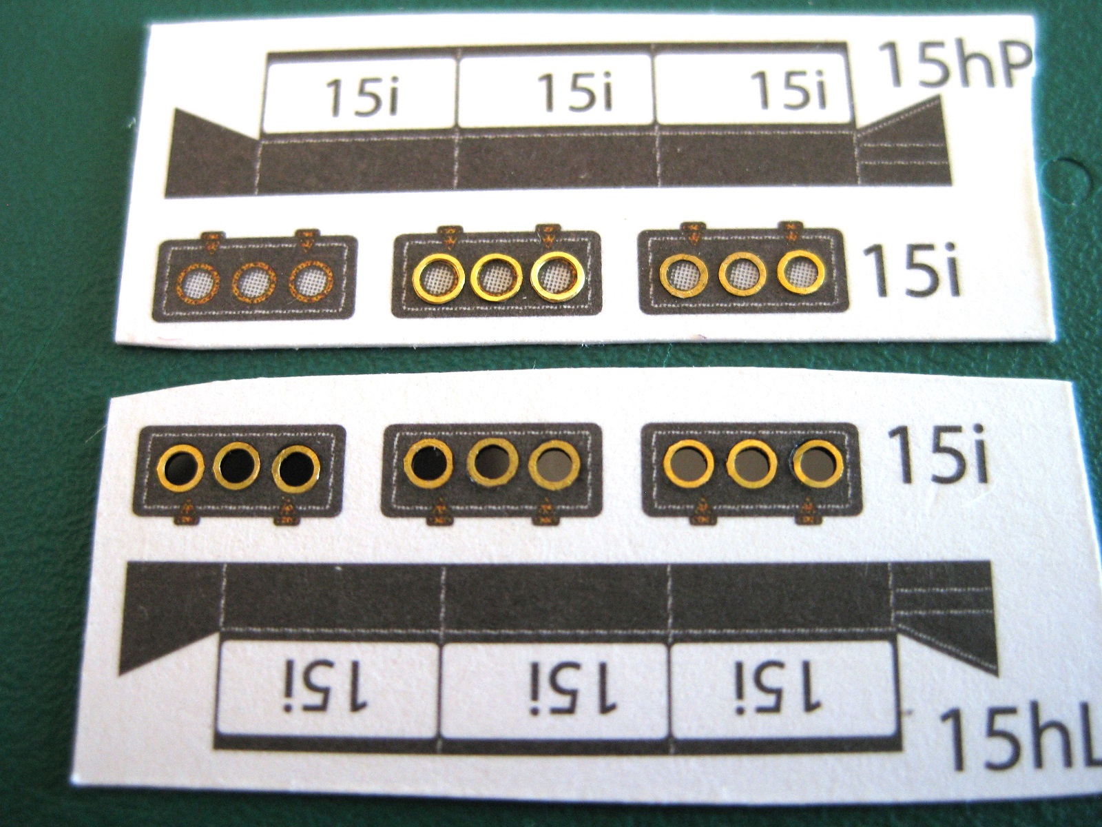
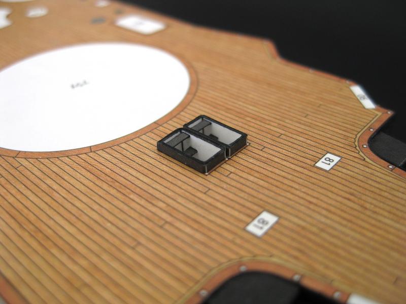
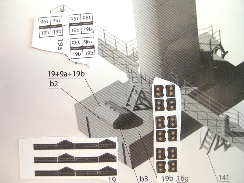
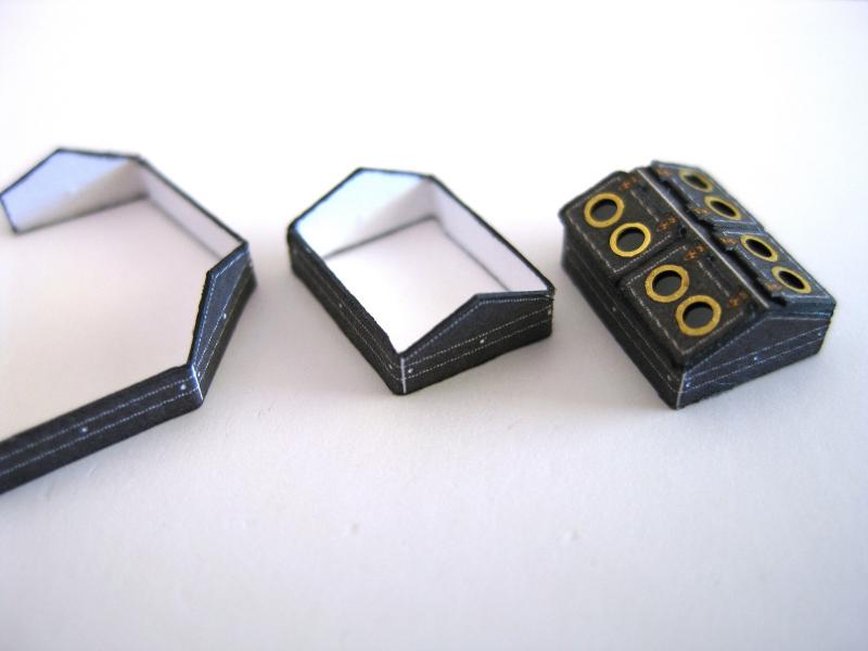
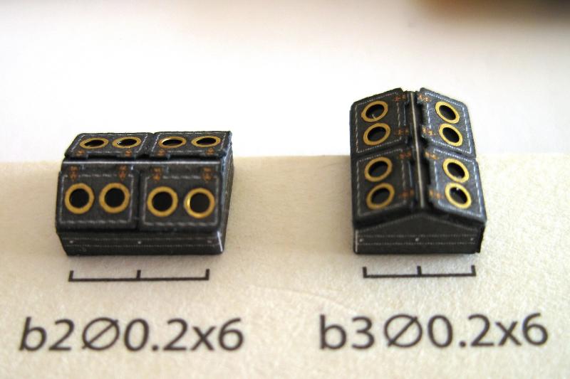
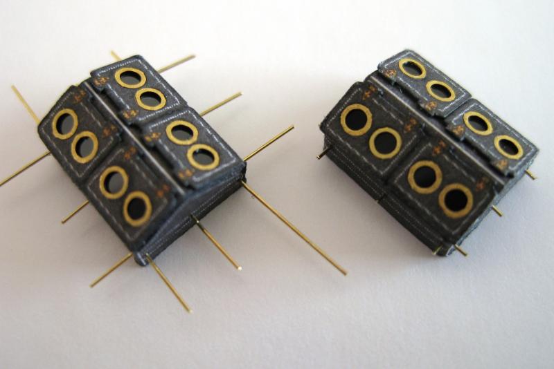
Thanks to everyone for the likes. Hi Nick, I am glad you are getting some ideas from my log. I have just started using the Roket glue myself so experience is a bit limited but really liking it so far. Thanks for the heads up on the Glue n’ Glaze. I have watched some YouTube videos and it looks like it would fit the bill for the bridge windows when I get there. I see the place I got the Roket glue also stock it so will keep it in mind when I get to that stage. Hi DR, thanks for your comment. I would say it’s more like I am getting to get grips with card modelling! One of the challenges I have found with card modelling is just how much thought needs to go into putting them together, what with incorrectly shaped parts (as the example above) and dealing with diagrams which only show the completed assembly. They usually don’t show you how they got there. The last parts of this structure are some skylights which run down each side. The top left strip shows 3 porthole options; the printed portholes (which I do like), middle skylight is the 1.6mm GPM portholes which are slightly too big and the right hand sky light shows the small portholes from the Borodino detail set which I forgot about. The detail set ones were a better size for fitting in the limited space but I don’t like working with these. They are so much thinner than the 1.6mm GPM ones and difficult to handle. The bottom strip shows all the skylights punched out and the portholes inserted with mylar glazing. The mylar had to be trimmed very close to the portholes so it didn’t go past the hatches. The port-holing (?) was done prior to cutting out as the parts are pretty small and to prevent the punching operation distorting the sides. The complete skylights are pretty simple only having 4 parts; the body and 3 hatches. The fold lines were carried through to the backside and scored ready for folding. The 2 ends were folded inwards and the top down and then glued up. Here the glued up body is sitting on the end on a square so I could press the hatch down flat for gluing. The hatches were cut out using the same method as the doors in the previous post. I glued in the middle hatch first then the 2 outer ones so I didn’t run off the end of one side. The finished skylights glued into position and that completes Assembly 15. Final thoughts? Well firstly this is the kind of structures/components/assemblies I love doing. I reckon it turned out not to bad and pretty chuffed with it. It’s a pity about the forms being wrong but this type of thing crops up with card modelling and it wasn’t a show stopper, just annoying. Certainly I could have done better. The main thing that springs to mind is some of the areas where the top and side skins butt against each other aren’t perfect; the side skin popped up proud or dipped down below the top at some areas. You may have noticed a couple of white squares on the top of the structure, well this is for a couple of additional skylights (Part 19) so I thought I may as well do these now to add a bit more detail to the structure. There are a total of 3 No.19 skylights; 2 for the completed structure above and another one for a different part of the build but I decided to do all 3 rather than come back to do one later. Again not much parts to these; a base, a top and 4 little hatches with portholes. The diagram also shows that I need to add hand rails b2 and b3 round the perimeter of the skylight and these will need to be made up with 0.2mm brass wire. The steps shown to make the basic skylight. I did pin prick the handrail holes before cutting anything out for ease of access. The bases were cut and folded at the bend lines as normal and the ends glued together. The last step shows the top with the hatches installed as one unit. I did also try placing the top first and then attaching the hatches. Both methods have pros and cons but either or is fine. The space for portholes on the little hatches is starting to get tight for space! Two of the three completed skylights shown next to the handrails required to be made from 0.2mm brass wire. Rather than try and mess around with tiny little stubs as they show I chose another way to do them, which was easier but still encountered problems as discussed below. Had a lot of problems doing these. Firstly the holes I had previous pin pricked had more or less closed up due to handling for the construction and of course the 0.2mm brass wire wasn’t stiff enough to re-open the closed up holes. Secondly I went back to the needle to re-do the holes but without support the needle just pushed the sides in instead of puncturing the paper. To get round this I headed to the hardware store and picked up a sheet of 2.5mm balsa wood and made smallish 8mm x 6mm (give or take) blocks and glued these inside the skylight. I was then able to use the needle to re-do the holes. The brass wire was dipped in some CA glue and fed into the holes. The wire could be pushed quite a ways into the balsa easily enough. To trim the ends to length I placed a piece of 0.5mm card next to the wire and used nail clippers to trim to length. I think 0.5mm supports is a reasonable length for working to and visually for the scale as it would relate to 100mm (~ 4”) full size. Probably still a bit over scale but smaller interferes with constructability (for me anyway). To do the horizontal handrails I have never encountered so much frustration in all my days!!! I honestly tried 4 different CA glues, I tried brass wire and 0.2mm elastic rigging thread (saw this used on another website build log to great effect) and finally ended up using good old PVA glue on brass, which I then dabbed the joints for good measure with some Roket card glue. As this was the first time I had done these there were lots of lessons learned. Main one is to spend the time cutting the handrails to length before gluing for a neater finish, which I did for the shorter end rails. I glued over length pieces and then trimmed back to the support with the nail clippers again. Surprisingly the glue joint wasn’t affected by this but couldn’t get right up to the corner because of the glue. Secondly if cut to final length first the PVA alone would have been fine and I wouldn’t have such bulky joints. The first skylight I did to try out stuff on and not shown here as too embarrassed I painted the handrails with a 00 brush and Tamiya matt black. Despite thinning it still went on clumpy and of course it is ‘Black’ not like the printed ‘not quite black’ of the paper so stands out. For the 2 skylights in the photo I used a cheap hard block of black water colour and used this as it went on smoother with only the odd lump but also I knew it would dry out a more subdued black better in keeping with the paper colour. Lastly here are a couple of shots with Structure 15 and the additional skylights 19 on top, in their place of residency on the hull. To say it was a tight fit under the ‘bridge’ is an understatement. In fact it was so tight it didn’t fit! I know why it didn’t fit as the side skins on the structure actually peep past the form but I didn’t want to trim this as it fits nicely on the deck and more importantly, which I forgot to mention in the log, the end skins have very slight curves cut in them to account for the deck camber. If I started hacking away at the structure skins I know I would end up with gaps. So the only resort and due to access on the bridge was to very gently sand the bottom of the bridge skin with an almost smooth diamond photo-etch file and only sanding on the in stroke towards the printed surface so I didn’t snag and tear out the bottom edge. After an age doing this the structure slips smoothly in and out like a glove LOL Well that’s one structure and some skylights knocked off the list. I will probably have a break for a day or 2 before getting on with something else. I really enjoyed doing this and will most likely make a start on structure 16, which is very similar but also has a funnel. I know ,I know the hull won’t skin itself but I still don’t feel ready for the challenge of that yet! Cheers Slog


- 244 replies
-
- 12
-
-
- borodino
- dom bumagi
- (and 1 more)