HOLIDAY DONATION DRIVE - SUPPORT MSW - DO YOUR PART TO KEEP THIS GREAT FORUM GOING! (Only 13 donations so far - C'mon guys!)
×

Captain Slog
-
Posts
904 -
Joined
Content Type
Profiles
Forums
Gallery
Events
Everything posted by Captain Slog
-
 Hi Greg, Enjoying the start of your build. Can you explain the process for gluing the large flat photo etch deck plate to the plastic and what glue you used? Cheers Slog
 -
Hi SiF, Looking good so far. Have you thought about edge colouring your cuts to remove the whiteness of the edges. I have been getting good results using Faber Castel PITT artist pens as they don't bleed into the paper. You could also use artists water colours, water colour pencils or even model paints (enamel or acrylic) to name a few options. (The model paints may interfere with edge to edge gluing though if you are using PVA) Cheers Slog
- 27 replies
-
- 1
-

-
- san salvador
- maritime museum
- (and 1 more)
-
Awesome, love the guys doing Judo. I saw an example of this kit with washing lines and clothes hanging up and a mat laid out on deck with the guys sitting crossed legged round it with the 2 guys throwing each other in the middle. Was like a snapshot of day to day life on board.
-
Great stuff Greg, I am settling down to follow this monster, looking forward to it. Cheers Slog
-
Wow! Apologies Grant I only stumbled across your log today. Beautiful work. I will need to spend a bit of time going through it all! Cheers Slog
- 339 replies
-
- 5
-
-
- dumas
- Chris-Craft
- (and 3 more)
-
How very true. I am about to start doing twenty 3" guns which consist of thirteen paper parts (as well several wire pieces) and have found 3 different parts all labelled as '10e' One part of the 3 is obvious but the remaining 2 are not so clear as the assembly diagram isn't very clear. I can be doing without that kind of fun! LOL Cheers Slog
- 27 replies
-
- 1
-
-
- san salvador
- maritime museum
- (and 1 more)
-
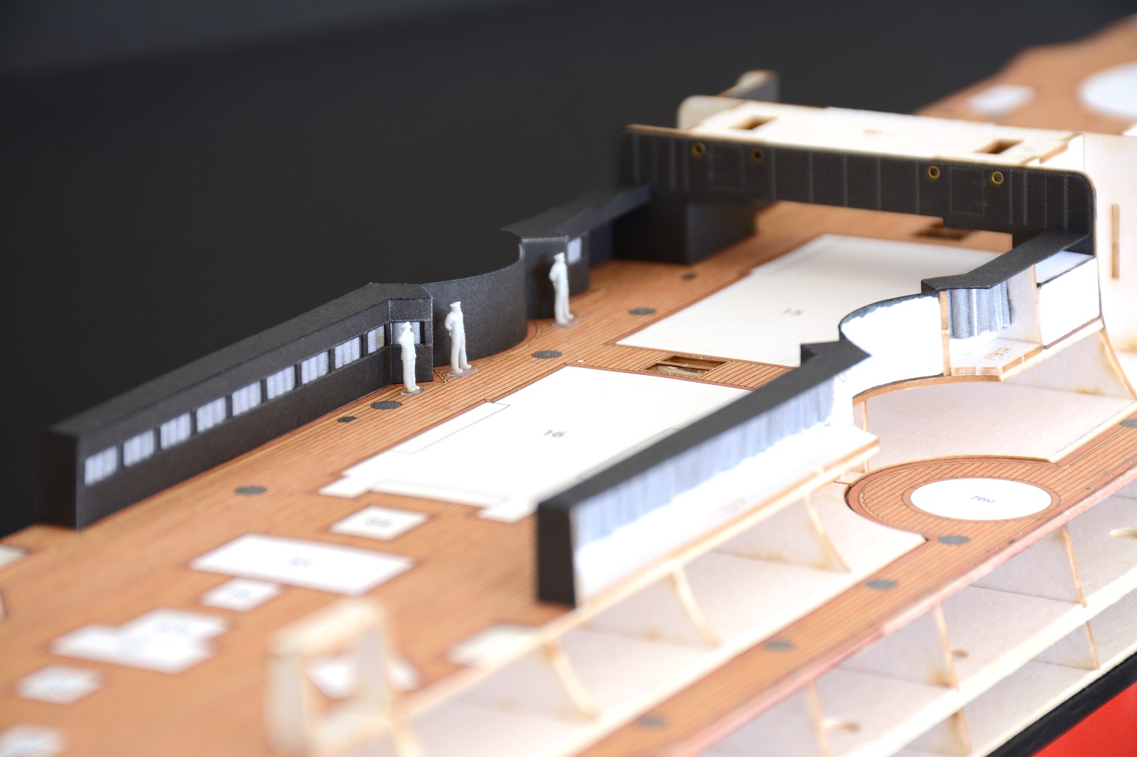
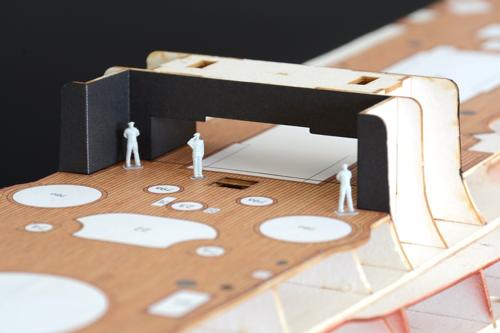
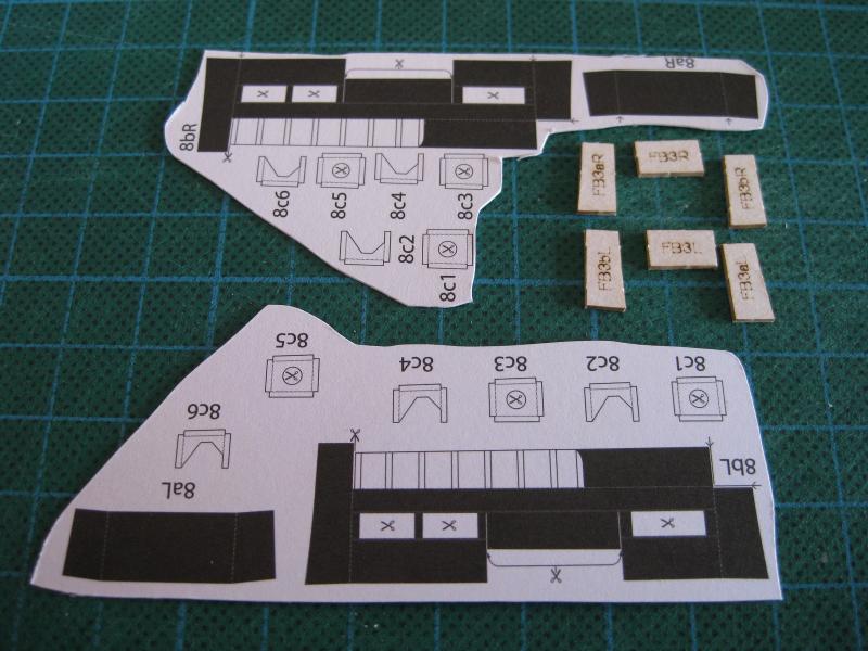
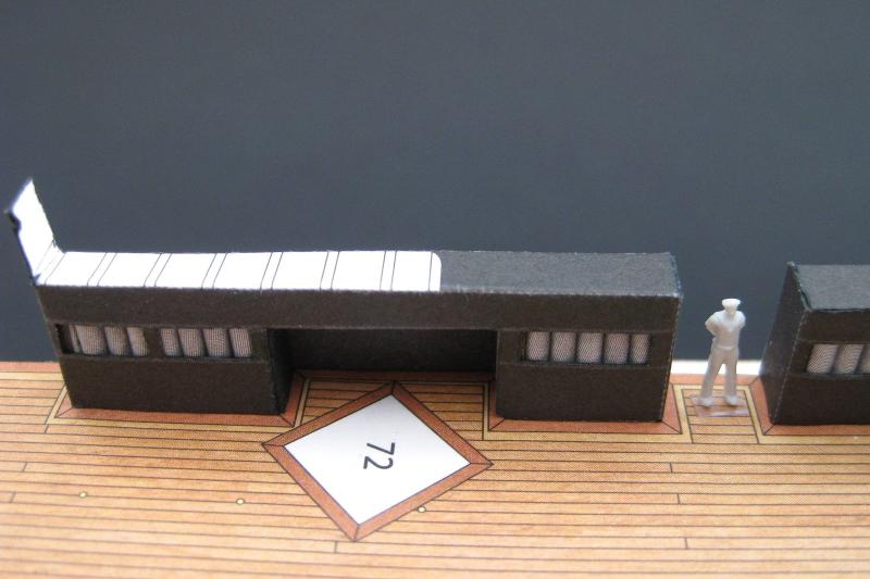
Hi guys, thanks for all the nice comments and the likes. Sam, I have been using the Swann Morton (SM) knife for quite a bit now and on the whole my findings are quite favourable. What I like in particular is that I find it easier to cut the edges of the paper square. Believe it or not even with thin paper it is possible to put a bevel on the edges due to the angle the blade has been ground to and this needs taking in to account when cutting. With the Excel blades I found it hard to consistently cut square edges. I think the angle of the blade grind on the SM blades may be different which may suit me better or perhaps the flat handle gives a better visual cue on the cutting angle. I still reach for the Excel knife now and then, particularly for doing a rotating chopping cut as they have a deeper heel at the back to rotate the blade on. Okay on with the last 2 rear side structures. I won’t go into detail as they are essentially the same structure as shown in the last post except shorter. In the photo there are small square supports (Parts 8c) which I haven’t done yet as these glue to the top to support the boat deck I believe. These will be too vulnerable to place just yet. The finished structure in place. I actually like the space where the sailor is standing as there are doors here in the hull sides which lead to external stairways down to the lower deck. The nice completed example I have seen of this kit has the doors open which looks good and will do the same. I will probably do the 3” casemate guns next as they are number 10 on the plans (so must be needed shortly) and I believe they will need to be installed before the hull skins go on as I don’t think the openings are large enough to manipulate the guns into position from the outside. After that there should be nothing left to do prior to skinning the hull. Cheers Slog
- 244 replies
-
- 9
-
-
- borodino
- dom bumagi
- (and 1 more)
-
Great to see another card build log to follow. Looking good so far. Cheers Slog
- 27 replies
-
- 1
-
-
- san salvador
- maritime museum
- (and 1 more)
-
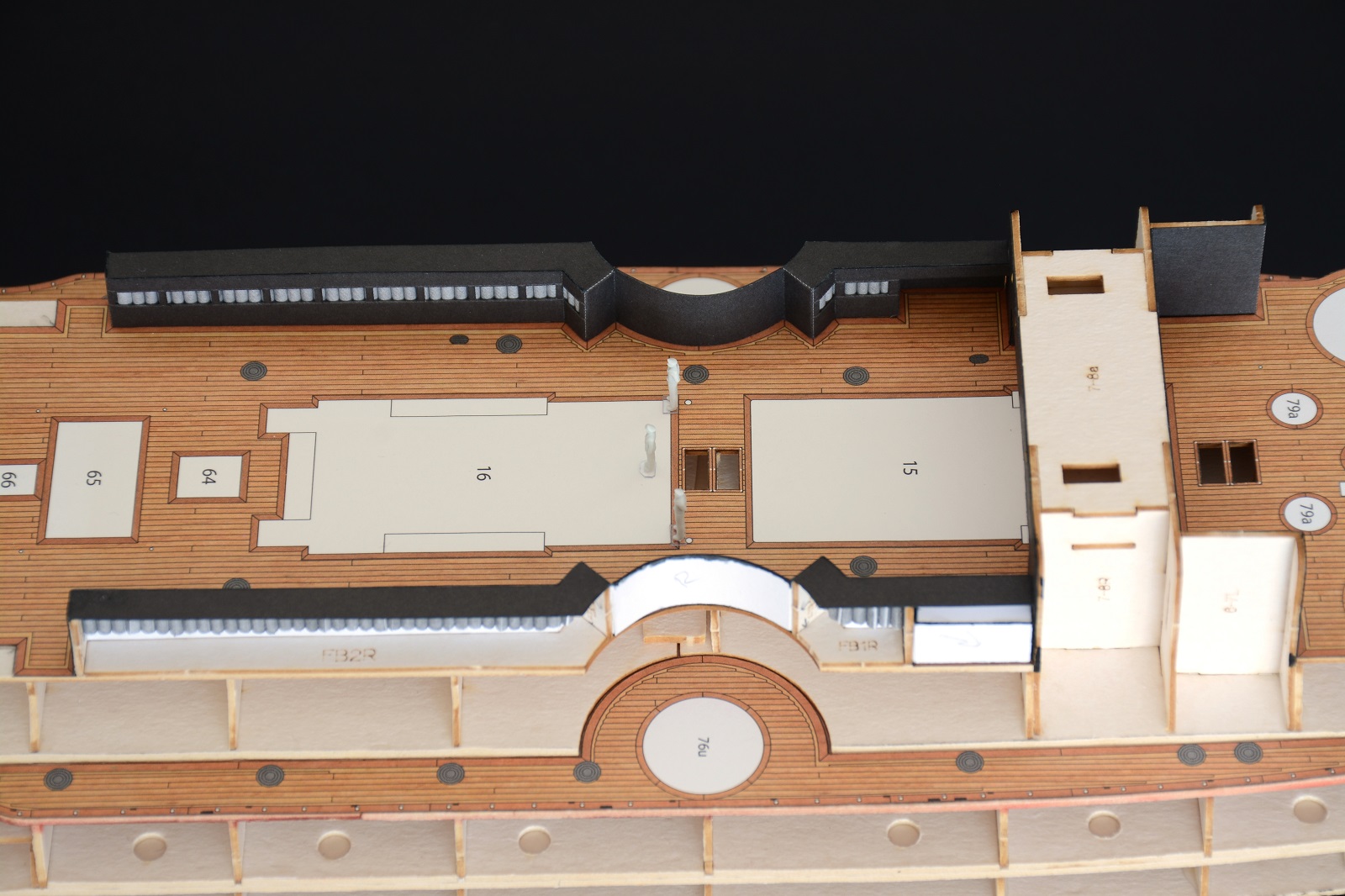
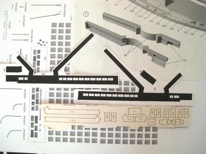
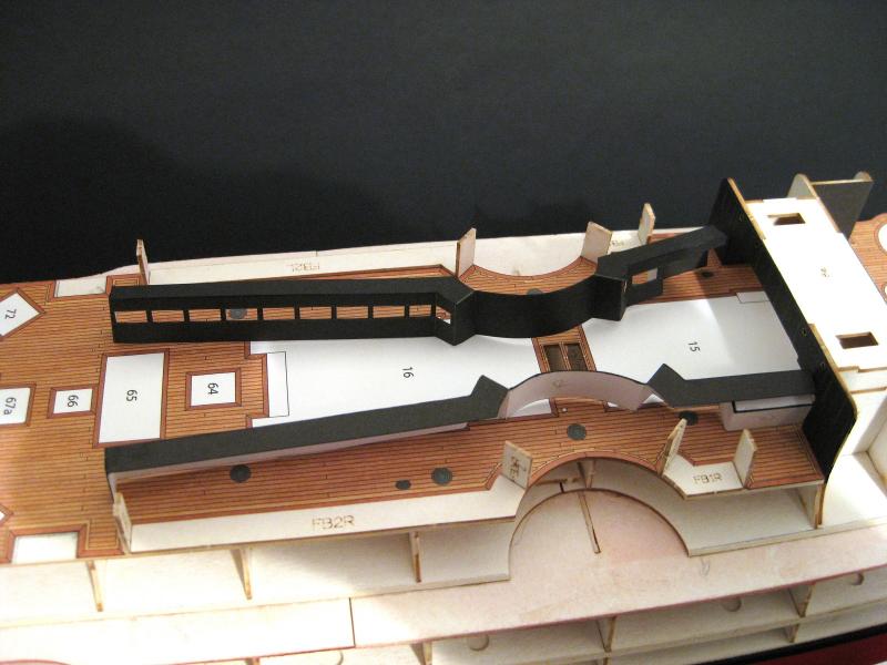
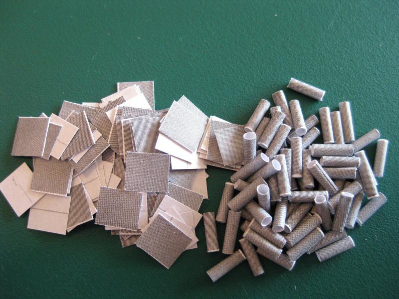
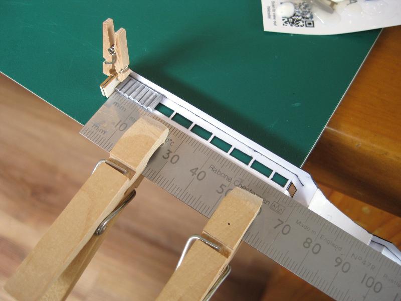
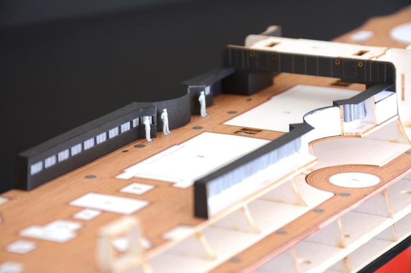
Hi all, moving on to the next hull sub-assembly. These run down both sides of the deck and hopefully will end up looking like what is shown on the diagram. Google translator was a bit iffy but I think these are either the sick bay or maybe just crew bunks but I gather they had beds inside. Also shown in the photo is a sheet of thinner paper with lots of grey rectangles. These are supposed to represent canvas curtains/drapes/screens for the windows once they are cut out. You have 2 options here, either place directly over the window opening in single parts or roll each rectangle round a 1.5mm rod to form tubes and then glue the tubes in to represent drawn screens as shown in the diagram. Me being me, I have opted to go with the rolled tube method as I think the effect will be a lot nicer than flat boring grey windows. I am not sure whether these windows were glazed or not but either way I am not putting in ‘glass’ as might interfere with gluing in the ‘curtains’ Also in the photo are some laser cuts parts which form the internal base and side supports for the structure. The laser cut parts cut out and glued into place. The only thing to take care of here is the orientation of the vertical supports as they aren’t perfect rectangles to account for the slight deck camber. They also need a quick swipe with sandpaper to knock of the little nibs where they were attached to the card sheet. Here is the port side structure cut out and commencement of folding and gluing. The windows were cut out first using the chisel method as previously described. There were 3 different widths required and I just narrowed down the 2 blades used previously and only needed to grind one other from scratch. I have been using a Black 199*** Faber Castell PITT artist pen to do the edge colouring but noticed when doing the anchor shelves it was a little too black. I tried a Cold Grey VI 235*** pen on these parts and I think it is a much better match for the ‘not quite’ black printing. With a piece such as this with multiple bends and folds in different directions I find it helpful to make up a bending plan of attack. Basically imagine going through the order of bends in turn so as not to fold yourself into a corner so to speak. In this case I actually rough sketched the part and numbered each bend and fold in order. Even doing this I made a mistake with the long blank strip between the window sections as I bent it the wrong direction and glued it to the small internal curve. Luckily I only did one of a potential 4 before I thought something wasn’t quite right. A quick check of the diagram showed my error. This wouldn’t of happened if I checked the diagram when doing up my plan! I was lucky in that I sliced the joint apart without too much problems. Both structures bent and glued up and shown next to the supports after a trial fit. The starboard ® (closest to the camera) was the one I accidently bent and glued incorrectly and the curved strip s a little worse for wear but should be okay once glued in place and with the outside curve glued back to back with it. Luckily I test fitted them as I will need to leave space for the vertical supports when fitting the ‘curtains’. The fit of the parts to the laser cut forms was spot on. The ‘curtains’ as described earlier are small rectangles of thinner paper rolled round a 1.5mm brass rod. I cut out a couple of curtains to trial roll and glue to see of any issues. It turns out the width of the rectangle is near as dammit the circumference of the rod. Since I didn’t fancy edge gluing 177 tiny tubes of thin paper I decided to leave a bit extra on one side when doing the mass cutting out. The little extra material left on meant I can lap and glue the ends quicker and easier. Turns out I still didn’t leave enough extra and was still a pain to roll and glue. I checked a rectangle against the window opening and could still have enough length to cover the window if I turned it on the long side and rolled this. The overlap is small and will be placed at the back so won’t be seen and not big enough to change the diameter on the 2 sides which touch the other tubes. The photo shows the total 177 parts but I only rolled enough curtain pleats ready for hanging in the sick bay LOL The rest are for the similar structure further back. With the sides all glued up it was time for the haberdashery. The part was held down flat to the cutting mat with a ruler and a couple of clothes peg so the curtains went in flat. On the left I used a piece of scrap laser cut board as a spacer for the vertical support. I also used another piece of scrap on the outside so the mini clothes peg didn’t damage the surface. I had to hang the part over the mat due to the shape. A dab of glue was placed on both ends and sides of adjacent curtain and the next tube dropped in making sure the seam was to the back. A finished row of curtains. On the back side I brushed glue between the touching tubes and then along the bottoms of the tubes where they touch the wall. I decided to only do the main row of curtains off the hull and will do the returns once it is glued in place due to the lack of room trying to glue to the vertical supports. I like the effect of the pleats and look a bit nicer than a flat grey strip; saying that I doubt much of it, if any will be visible once the boats etc go over them. The structures glued in place and the remaining pleats added to the returns. As mentioned the fit of these were spot on. I haven’t glued the curved sections to the deck yet as waiting until the outside curve is placed before doing that. I also haven’t glued the top horizontal end to the bridging structure as again waiting until the outer skin is placed so I can tweak the height if necessary. Next up will be another pair of structures very similar to these but smaller and fit aft. Cheers Slog


- 244 replies
-
- 11
-
-
- borodino
- dom bumagi
- (and 1 more)
-
Another stunning build completed. That's quite a fleet you are building up Looking forward to the next one. As Keith said don't wait to long in starting! Cheers Slog Incidentally I saw that same Yamato model in my local hobby recently buried away in back. They are more RC cars and planes orientated but have a wide selection of other modelling stuff)
- 342 replies
-
- 7
-
-
- dreadnought
- zvezda
- (and 2 more)
-
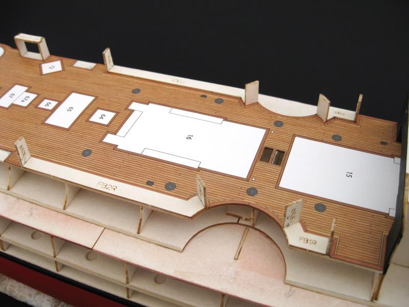
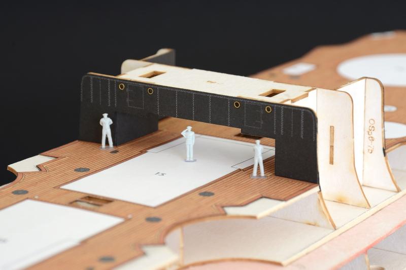
Hi DR thanks for the comment. I would be interested in hearing what card models you have in your stash Hi Sam, watch your fingers! Let me know how you rate them, I am still a bit undecided. Not sure how the screw punch would work on veneer, they can cut fairly heavy card stock I believe. Thanks for link Greg, I did another search and quite a few Aussie stockists came up, although some were limited on cutter sizes. I will probably end up getting one down the track as they cut rear neat holes quickly. A little more progress but nothing new or exciting. I worked on the port side shelf and of course the complicated bit was quicker, easier and fitted better the second time around. As previously mentioned I am stopping there for the anchor shelves for the time being. With the anchor shelves on hold I installed the top, rear deck with nothing of note to report. Now that the top, front and rear decks were fitted I was finally able to glue in the bridging structure (I wish I knew the correct term for it) that I made away back near the beginning of the build. The sides of this are covered with the side hull plating. Now that the top decks are installed I will concentrate on the other top side structures which run down the sides of the deck. The cut outs for these can be seen in the photos and these also are covered by the side hull plating. Cheers Slog


- 244 replies
-
- 12
-
-
- borodino
- dom bumagi
- (and 1 more)
-
Looking forward to following another Endeavour build. Cheers Slog
-
Ah, that makes more sense! I did look into getting a screw punch previously but had a hard time finding the genuine ones. I came across some screw punches pertaining to be Japanese but weren't and pretty poor quality and the branded ones aimed at scrap bookers were terrible and limited in cutter sizes. If I remember correctly I think it was Lee Valley in the states who sold genuine ones and even got an e-mail quote on shipping but they didn't stock all the cutters. I also found a Japanese store which specialises in shipping genuine Japanese goods overseas and they stocked the punch and all the cutting tips but didn't place an order as the store was an unknown quantity to me. I probably have the details saved on the computer somewhere. Cheers Slog
- 244 replies
-
- 2
-
-
- borodino
- dom bumagi
- (and 1 more)
-
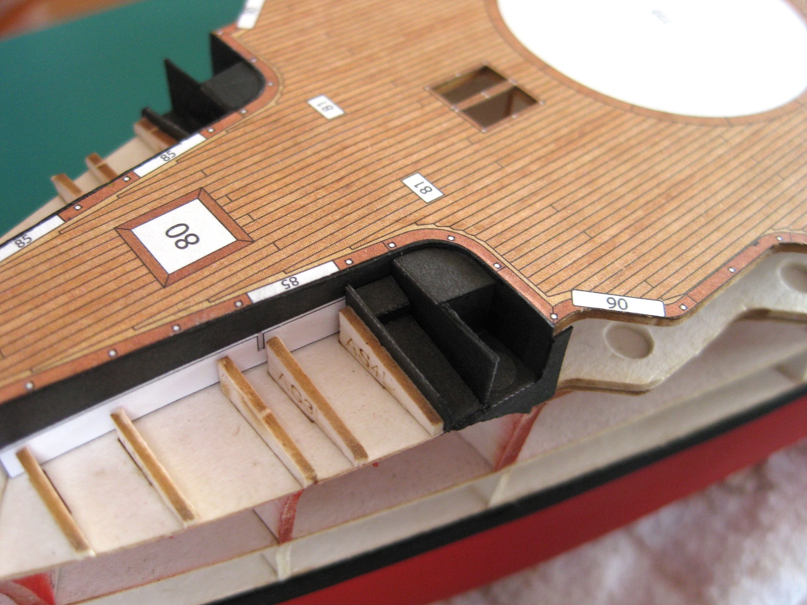
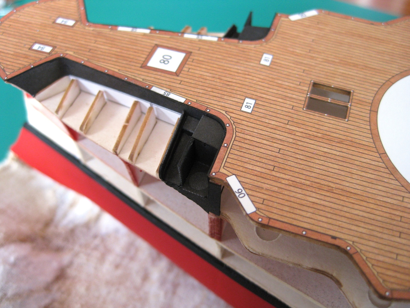
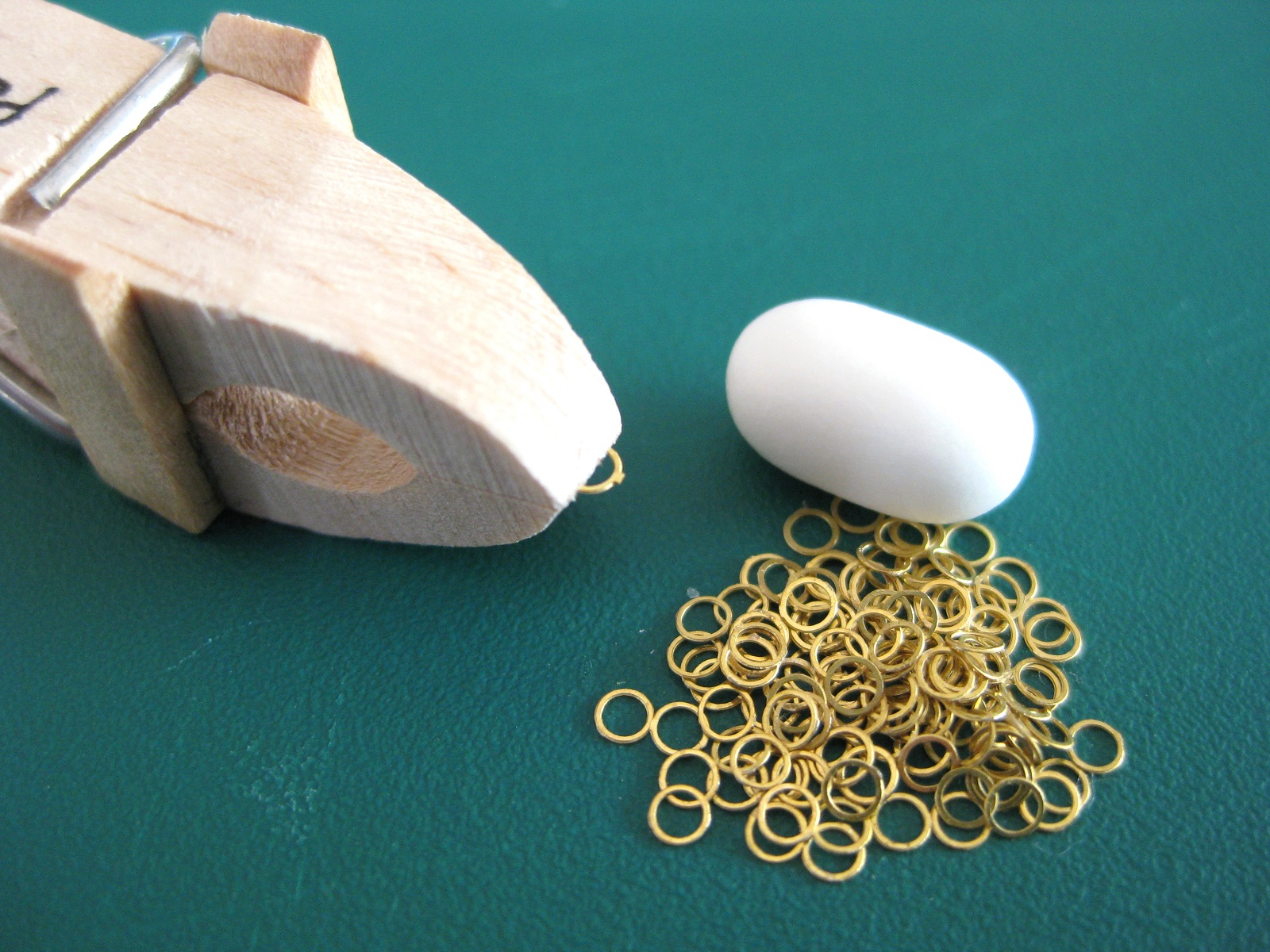
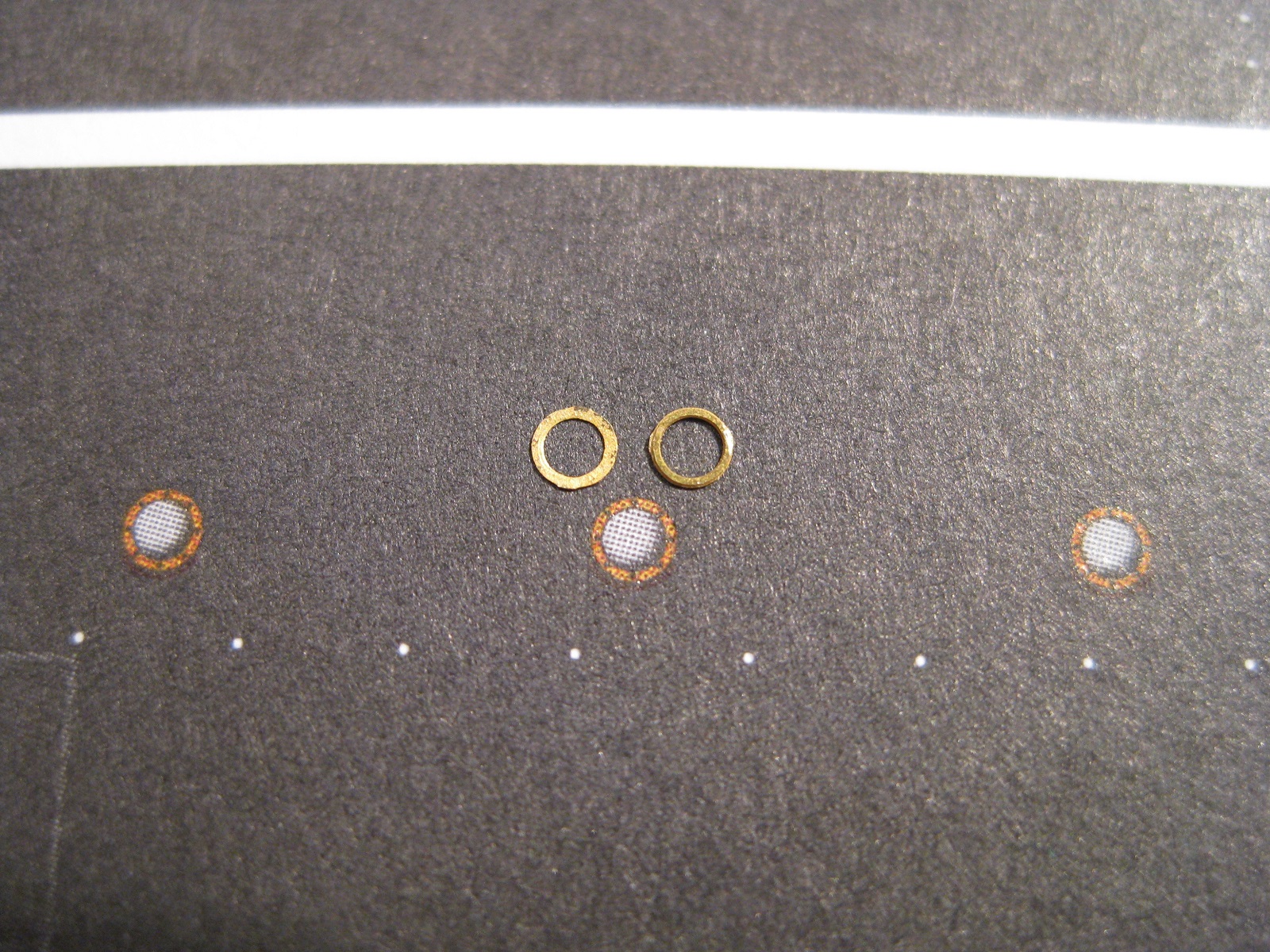
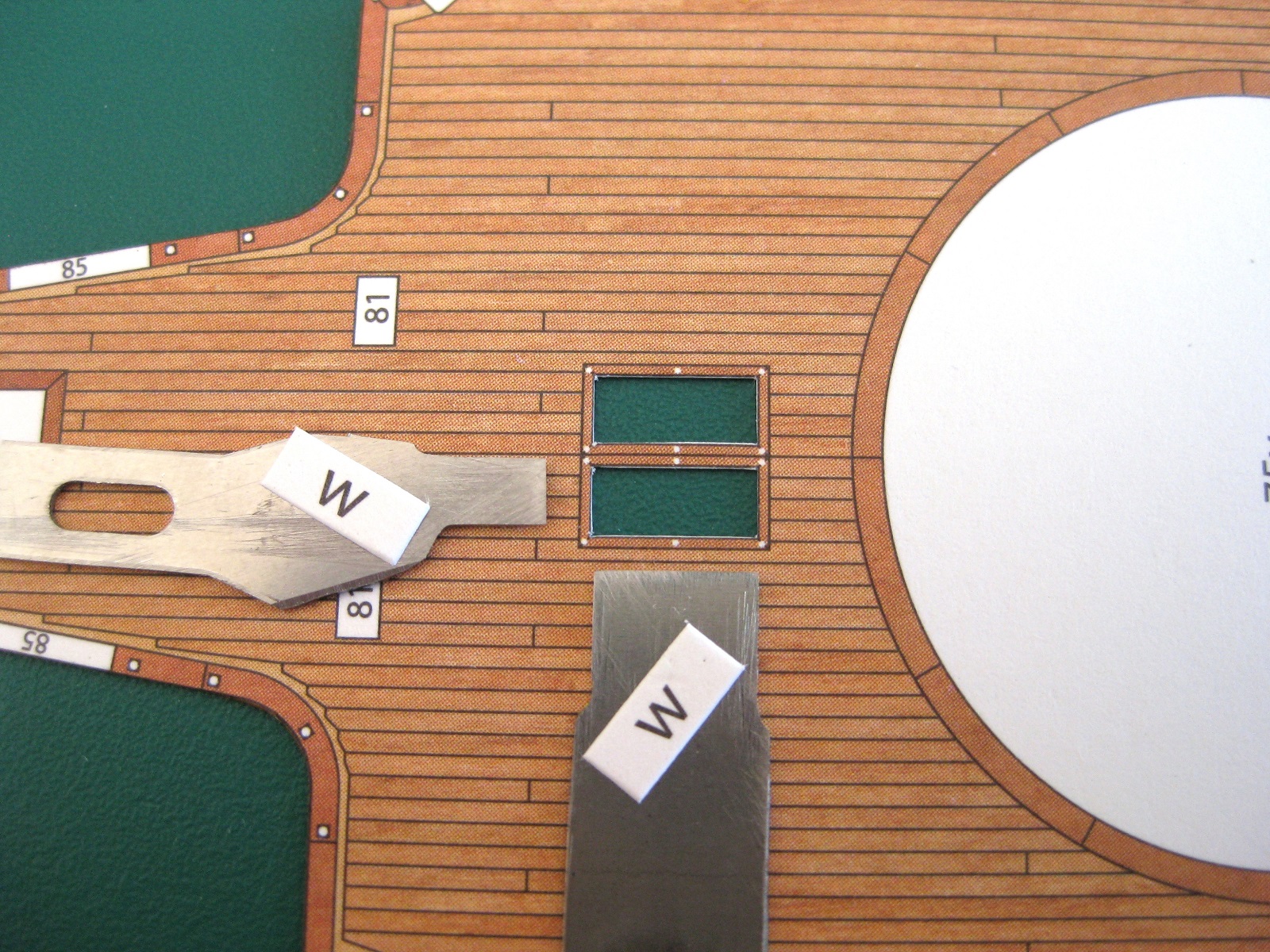
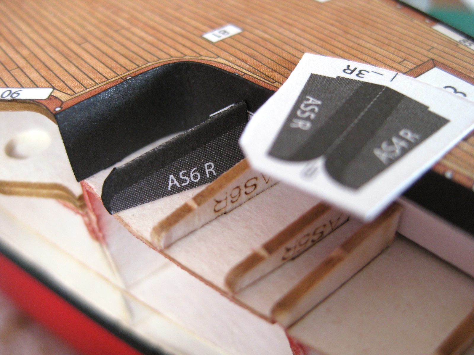
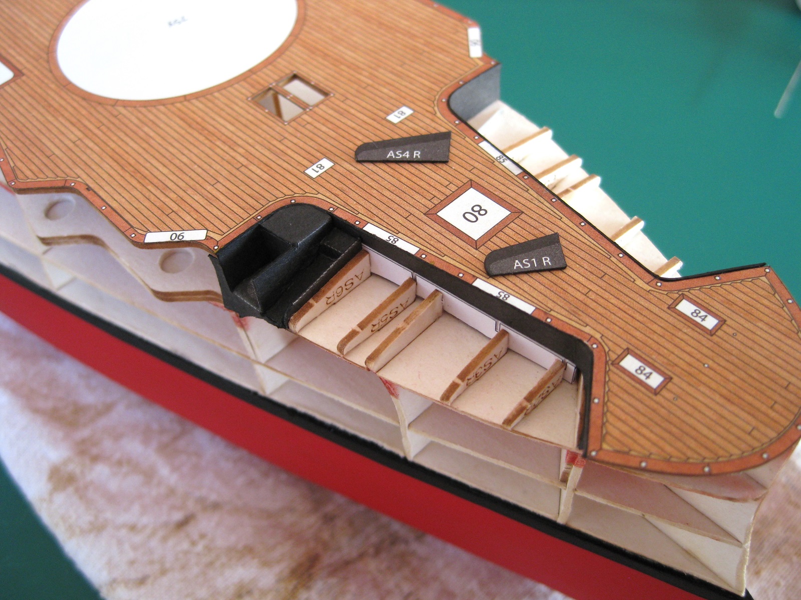
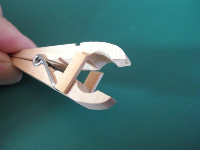
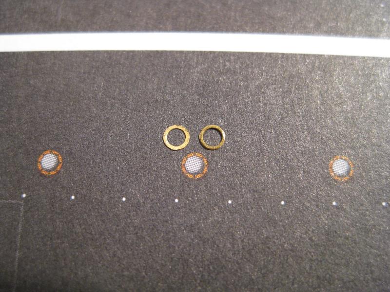
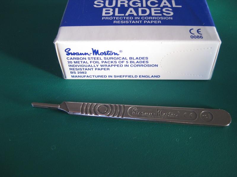
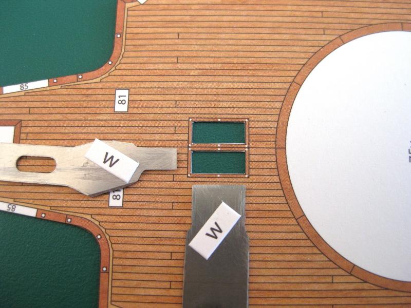
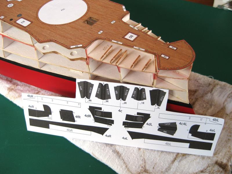
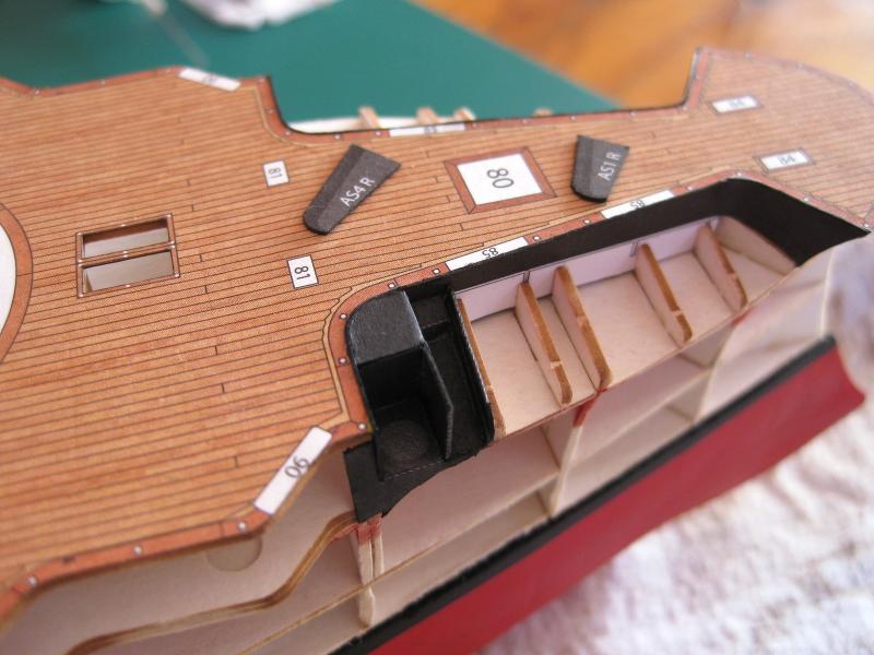
Thanks Jeff for the comment and to all for the likes. Okay here we go with some more progress and a few other bits and pieces. Due to limited modelling time I am squeezing in bits and pieces where I can but still keeping to the general flow of the plans and are all hull related. The temptation to jump to more exciting parts such as gun turrets and the superstructures is strong though! First up the photo etch ports holes for the hull side skins. I counted all the larger portholes, which I will use 2mm GPM ones and came to a figure of 144. There are also a number of smaller 1.6mm portholes which I haven’t cut out yet but will use GPM ones again. The problem was how to hold them for cleaning up the 2 tangs left when freed from the PE fret. I initially tried tweezers but regardless how tight I held them the shiny brass against shiny tweezers meant they just spun round. I tried using the smooth part of the jaws of some pliers but they were big and awkward and risked crushing the tiny brass. I needed something small and grippy and ended up using a clothes peg where I had sanded down the nose so the jaws at the front were flush and sanded the sides so the porthole was accessible from both sides with the file. The photo shows all 144, 2mm portholes cut out and cleaned up except for the last one which is in the holder. It was so easy to use and the spring pressure alone was enough to grip the ring securely for filing so I didn’t suffer any finger fatigue gripping the peg. Also clothes pegs have a tendency for the legs to move laterally when opening and closing so I glued on a couple of strips of spare decking planks I had to each side of one leg so the jaws remain aligned when opening and closing. After cleaning up 144 portholes I had a look at the photo-etch detail set specifically for the Borodino and low and behold there were 144 large ports holes! I actually think I like these better as the ring is wider and will show up more and look more in keeping with the Victorian era of these ships. Unfortunately the PE of the detail set is so much thinner than the GPM stuff which means that they will not fill the thickness of the paper and have space behind them and the floppy disc windows and I guess more susceptible to damage during handling. The biggest issue though is I have no way of neatly making the holes for them as they are ever so slightly wider than the GPM portholes. The GPM rings fit nicely into holes left from the 2mm brass tube punch I use. So although nicer (IMHO) I won’t use them and will stick with the GPM ones. The photo shows the printed portholes with the detail set one on the left and the GPM one on the right. The difference doesn’t seem so pronounced in the photo compared to in the hand. Rows of them would have looked nicer though. I am trying Swann Morton scalpel blades for the 1st time (kind of). I have exclusively used Excel blades for my modelling but since my stock was dwindling I decided to order a box of 100 from an Australian on-line store I found with the cheapest price. (I don’t do eBay) They didn’t have 100 Excel No.11 boxes in stock but noticed a box of 100 Swann Morton scalpel No.11 blades for the same price and for an extra tenner got the No. 3 handle as well. I know there is a segment of the modelling community who swear by them saying they are sharper and last longer than the typical modelling blade. They are certainly a bit thinner than the Excel blades and although I can’t determine their longevity yet I didn’t notice any significant difference in cutting out parts which at this point is minimal anyway so hard to judge. A little anecdote; many many years ago when I was probably a pre-teen my old man did Napoleonic war gaming (so did I to a certain extent) and I remember he had several of the distinctive Swann Morton knife handles and different blades lying around. I don’t remember seeing any other type of hobby or craft knife. What I do remember though was the seemingly deadly, thumb nail puncturing, finger slashing act of changing their blades!!! So was a bit apprehensive of fitting the 1st blade. Turns out following the instructions and using a pair of needle nose pliers fitting and removing them is, well child’s play LOL Thinking back I am surprised I survived to reach adulthood unscathed what with the molten lead for casting armies of 25mm soldiers, changing scalpel blades with fingers and other modelling hazards lying about in his war gaming den! I went to glue down the top foredeck so I could get going with the anchor shelves when I noticed there are a few hatches to cut. It appears to be universal in card modelling that any openings to be removed are marked with either a scissors symbol or W (for waste I guess). The usual method is to just cut them out with knife. You would start by placing the knife point in to the corner and working out from there. I don’t like doing this for a couple of reasons. Firstly I am not ambidextrous so I am only comfortable doing half the cuts. The other half I find awkward trying to get orientated. Secondly I don’t like this for small openings to be cut out as I find it inaccurate. It’s okay if only doing large holes (for me). My method for cutting out small holes is to use my Dremel to grind old worn blades into a chisel the width of the side to be cut. This way the corners are all the same and hopefully a lot cleaner than doing it the usual method. The blades are held in knife handles as usual and pressed vertically down to make the cut The time taken to grind the blades to width is well worth it for clean holes and especially where you have multiple holes the same size, the time saving can be immense. (I started doing this when I had 5 holes to cut in 160+ tank track links). Important note: I have found when doing a row of holes such as ship bridge windows or for the example in the photo below where there is only a thin bar separating each window the order of cuts is important. Do all the cuts with the thin piece between them first then do the top and bottom cuts to release the waste. The reason for this is that the waste is still in place which supports the thin piece to be left during cutting. If you cut out in the other order, once the waste is removed the thin section is no longer supported and can be bent out of shape when the ‘chisel’ blade makes the cut of the next window. Hope that makes sense. In the photo I did all the long cuts first followed by the short ones to release the waste. With the holes in the deck done it was glued down and ready for working on the anchor shelves. Shown in the photo is all the parts to make up the anchor shelves with the exception of the side hull skins as these fold over to fill in between the vertical blades. I refer you to parts 4dR and 4dL; these were beasts to cut out and fold to form the boxes/supports for where I believe the anchor cranes are located. The vertical blades in the photo are marked with the laser cut form number against which they are fitted to. The shelf is constructed by fixing these vertical blades against the forms. As can be seen they stick up past the forms, the darker print being what will be exposed once the side hull skins fold over between them to sit on the tops of the forms. I have progressed as far as I want to with the starboard anchor shelf and I will do the port one next to the same state. I am going to hold off further progress here until the side skin is attached so I can work out what sides the vertical blades fit to as there appears to be discrepancies with some numbering and positions in the assembly diagram. The crane support area (4dR) can be seen all bent up and fitted against 4eR. This was a real tough bit to do and isn’t perfect as had some misalignment issues. Incidentally the part 4dR isn’t shown or numbered in the diagram and was a real head scratch it work out all the folds. Overall I had some alignment issues (my fault) some of which have been tweaked out and others will wait to see how they affect the side skins. Still, pretty happy with how they are going. Cheers Slog


- 244 replies
-
- 14
-
-
- borodino
- dom bumagi
- (and 1 more)
-
Outstanding work Greg, another one to be proud of. Cheers Slog
- 342 replies
-
- 5
-
-
- dreadnought
- zvezda
- (and 2 more)
-
Hi Sam, Very nice work on the masts. From your picture though I can't work out if that is one enormous chisel or an awesome tiny square! I like it! Cheers Slog
-
Hi Jeff, Thats a nice flue you scratched up. I like the stand for holding the yards whilst working on them! Cheers Slog
-
Hi Robin, The scale isn't 1:16 where 1 unit of model equals 16 units in real life. It is 1/16 where 1/16 model inches equals 1 foot in real life. (1/16" = 1' This works out to be 1:192 scale. The first photo says on the box the model length is 31 1/2" (800mm) Cheers Slog
- 68 replies
-
- 6
-
-
- Arleigh Burke
- BlueJacket Shipcrafters
- (and 1 more)
-
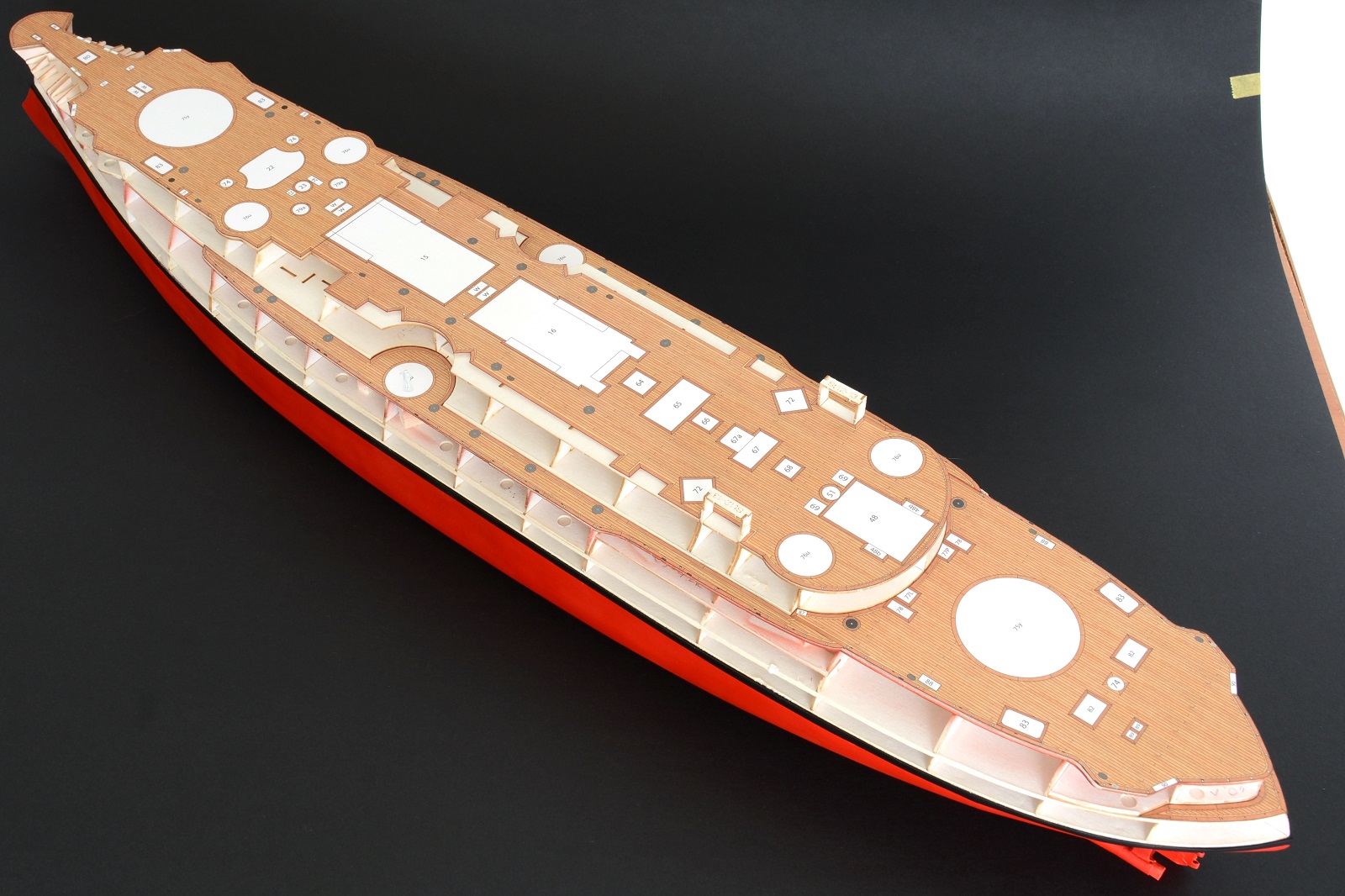
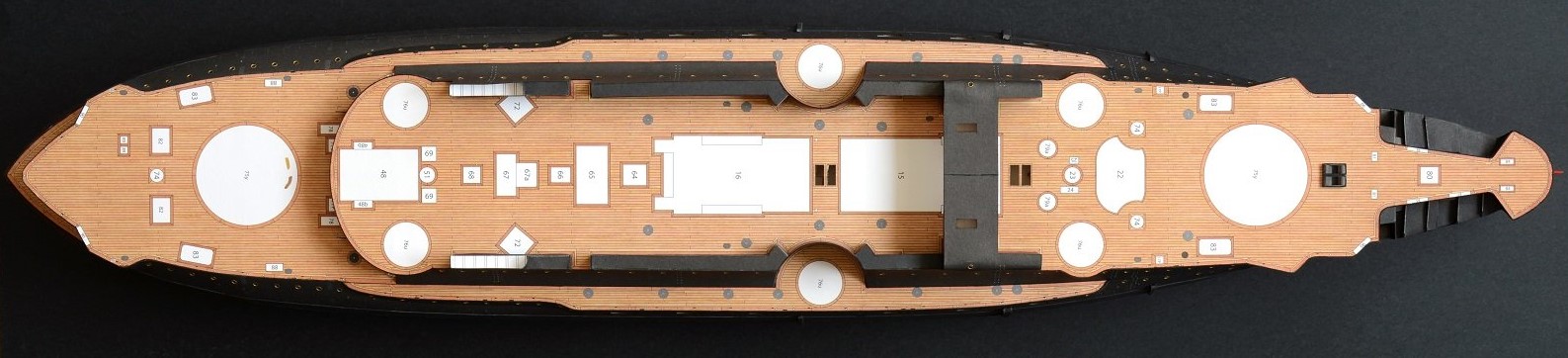
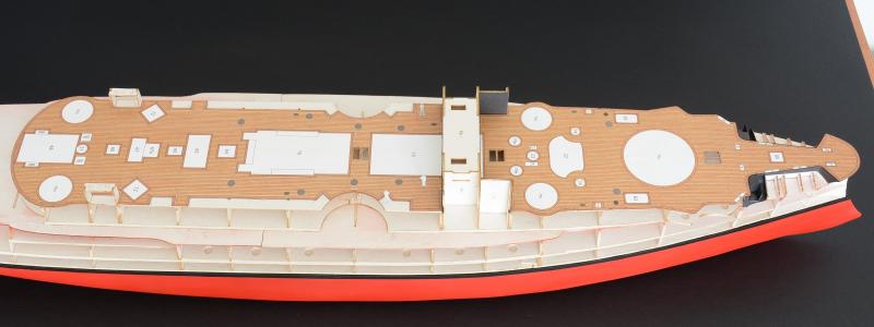
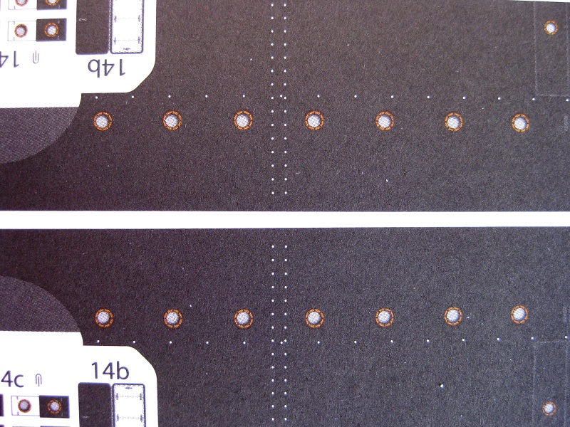
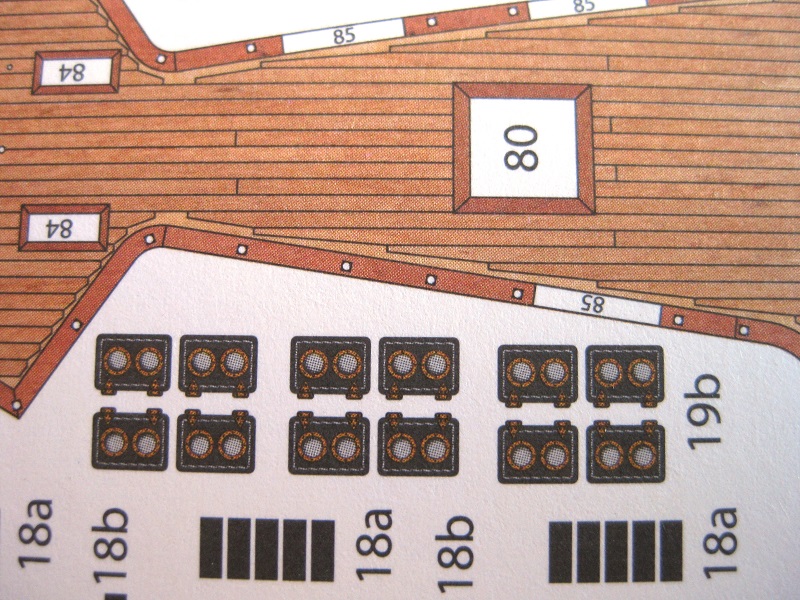
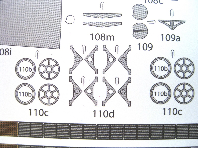
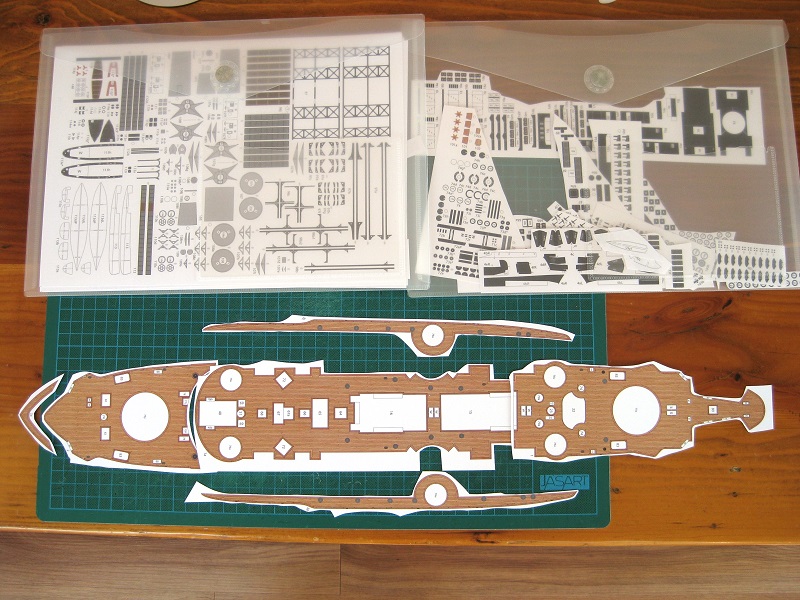
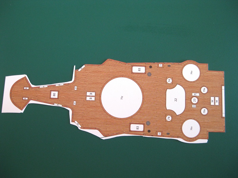
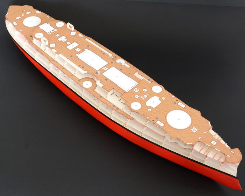
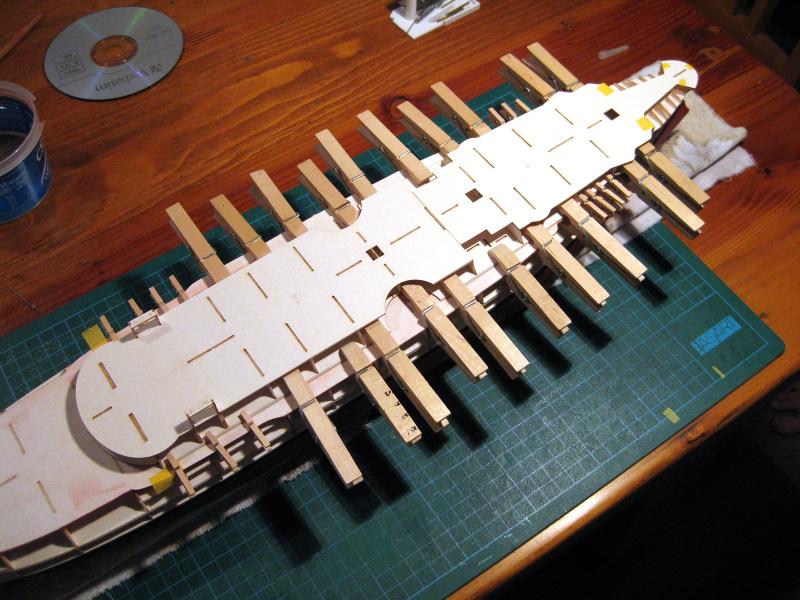
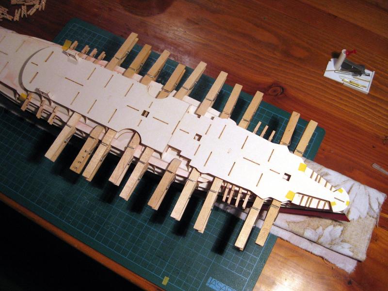
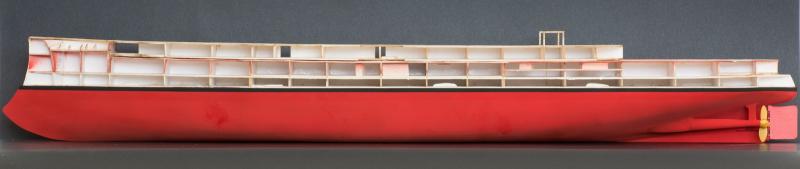
Hi Joel, yeah the wooden pegs are great for modifying, have a good few where I rounded the fronts on the disc sander so they can grip right at the front and up to an edge. The tiny clothes pegs in the previous photo are front the arts and crafts department and great for getting into tight spaces. The springs in them are surprising strong; sometimes the legs break trying to open them if the grain is wrong. Another favorite is bulldog clips but need to be careful they don’t dent the surface. Hi Ken, I hadn’t thought about reversing the legs. That would have come in handy for the previous glue up. Okay, haven’t done a great deal since the last update so I thought I would take the opportunity to go through some pros and cons of the kit, some things I do/have done and some progress shots. I think I have done enough on the kit to form some opinions on it both good and bad, not forgetting that some of them may be down to my inexperience and may not bother other modellers. Firstly the pros; I reckon the print quality is very good and the parts look well represented. Secondly the fit of the parts are excellent and any discrepancies would be down to my lack of experience. The photo below is another pro in my book. The horizontal and vertical rows of white dots are the positions of the horizontal hand rails and vertical step irons. The reason I like this is because other kits have hand rails and step irons printed on which if left look very flat and if fabricated and installed means there is a strange ‘shadow’ or ‘mirroring’ due to the printing underneath. I guess if you didn’t want to install the iron work in this kit then you would be left with white dots to deal with but I want to do the iron work so works for me. The kit supplies templates for all the iron work as well which is good so takes out any guess work. Now for some cons and I have touched on these briefly in the past. Firstly I don’t like the paper; it delaminates too easily during folding and rolling. Sometimes even free hand cutting despite a new blade sometimes has other issues. As a comparison the brief work I did on the Bismarck didn’t give me any cause for concern and the great deal of work done on Orliks Mazur made me realise how fantastic their paper is for all types of work performed. I would say the Borodino has the worst of the three. Another con I mentioned previously is the tight placement of parts on the sheets. I don't mean the closeness of the same part but with unrelated parts. Some parts are about 0.5mm to 1mm apart which I find frustrating as I like to rough cut out the part I want to work on so it can be maneuvered easier for final precision cutting. I can’t be only person who does this as I assumed it would be how everyone does it. The close parts placement wouldn’t be so bad if the paper as mentioned above was better as trying to split the parts leaves very little waste to trim off later which the paper doesn’t like doing very much. I believe this is a tactic to reduce the numbers of parts sheets required for the kit; pack them in as close as possible to save space. If they include just one more sheet to catch the overspill of spacing the parts out they could also have included another of my cons and that is the lack of solid colour swatches or blocks of print for the predominate colours. Other kits I have use empty spare space to provide solid blocks of print so you can use this to make replacement parts or to add extra bits and pieces in the model colours. The photo shows how close the parts placements are in a lot of cases. Finally my last issue is the lack of folding info for parts which are mirrored and folded together to provide colour and detail on both sides of the part. I mentioned this when doing the prop blades which weren’t a problem due to solid colours but in the photo below the wheels are a case in point of trying to mirror them accurately. Even if the line in the ‘fold part’ legend was extended down between the parts there would be no issue. Okay no more whinging; I am enjoying the kit immensely and will concentrate on making it to the best of my abilities although I will continue to point out any good things I come across. Okay here are all the decks rough cut out. In the photo I include how I store the parts sheets. I use 2 plastic document folders. One is for storing the complete sheets. As parts are rough cut out for working on other parts get freed from the sheet and these parts are stored in the second folder. I take care to keep the same part together with the part number so no confusion later. I also replace parts sheets back in the folders immediately once I have gotten off them what I need to reduce the chances of them getting damaged by lying about on the work surface. Another thing I want to point out which may not be obvious is to do with the cutting mat. I have used this one for many years and is in reasonable condition as I don’t abuse it but the surface is becoming quite worn and I found recently when cutting out parts, particularly free hand the blade sometimes wandered as it was tracking in cuts in the mat below. Well turn it over and you have a brand new mat. The backside material is identical to the front side the only difference being it won’t have any printed lines and or dots on it but it works the same. Double the bang for your buck. If I get another 8 years out of it I will be happy LOL All the decks cut out and placed on the ship. They are NOT glued down yet for a few reasons. Firstly they show up that I still need to do some fairing work on the upper hull sections. Also I want to check the relationship between the decks and black hull skins as they may need to go down in a particular order such as butting against over going under or over the side skins etc. The part numbers suggest that they can go down now but sometimes prudent not to rely on the numbering alone for construction order as sometimes can seem very arbitrary with little relationship. Next up is cutting out the side skins and replacing port holes. Cheers Slog

- 244 replies
-
- 13
-
-
- borodino
- dom bumagi
- (and 1 more)
-
Mate, can't go wrong with Iwata, top Japanese quality. I love mine in all it's shiny chrome goodness! The Airbrushmegastore where I got mine was $100 cheaper than locally and I believe the store is over your side of the country. http://modelshipworld.com/index.php/topic/2037-iwata-hp-c-plus-airbrush-review-moved-by-mod/?hl=iwata The only thing is it is 0.3mm needle which is good for small to medium stuff, but full hulls could have done with a larger spray pattern. I might look at getting a larger Iwata for that later considering I always end up painting my paper hulls anyway LOL There is a guy on here who did a whole series of youtube videos and covers airbrushes. (Paul Bud....something) anyway you will see what I mean about laying down large volumes for hulls if you can find them. I think the Iwata would be a good choice if you stick with the 1:350. The Airbrushmegastore also has all the spare and replacement parts for all the Iwatas so support is there. Anyway my 2 cents worth. Cheers Slog Edit: by the way your latest progress shots are stunning. I always wondered how labour intensive setting out and retrieving the nets would be in real life. EDIT EDIT: Apologies to Paul, his name is Paul Budzik https://www.youtube.com/channel/UCrdcVbQE5fUvTKxMbhnN_KQ
- 342 replies
-
- 4
-
-
- dreadnought
- zvezda
- (and 2 more)
-
Thanks for the nice comments guys. I am pretty happy how it turned out. As with anything I do, could be better but more than happy enough for me to move on…speaking of which! Yesterday I brushed on a decent coat of Humbrol Matt Cote which did darken it slightly but still looks good and it removed the couple of shiny patches on the port side. Also feels a lot safer handling it now. Tonight I had a look at the plans and the 4 lines of translated text about hull assembly and I may have been mistaken about skinning the anchor shelf before placing the top deck on. After a look I decided to glue the top deck on first for a couple of reasons. I may damage the skins with the top deck when placing on and there is a curve at the rear of the shelf which would mean skinning it free hand without the curve in the deck to follow. So its glued up now using my expensive state of the art clamping system LOL Cheers Slog
- 244 replies
-
- 11
-
-
- borodino
- dom bumagi
- (and 1 more)
-
Hi Greg, Zvezda do the Borodino in 1:350 and believe there is also photo-etch and wood decks available for that. Also I believe Trumpeter is doing or have done the Mikasa in 1:200 scale and Pontos are currently working on an advanced photo-etch set for it. That combo is going to be a big temptation for me! I think Tamiya have also recently released a re-tooled Yamato in 1:350 so that would be a fair undertaking with the PE. Cheers Slog
- 342 replies
-
- 5
-
-
- dreadnought
- zvezda
- (and 2 more)
-
Hi Greg, I am constantly amazed with each log update how much detail you cram into such a small scale! The picture with it next to the desk lamp gave the game away, I could swear looking at the other detail shots it was at least 2 to 3 times bigger than it actually is! Whats your preference with doing the rails individually or as bought? Cheers Slog
- 342 replies
-
- 6
-
-
- dreadnought
- zvezda
- (and 2 more)
-
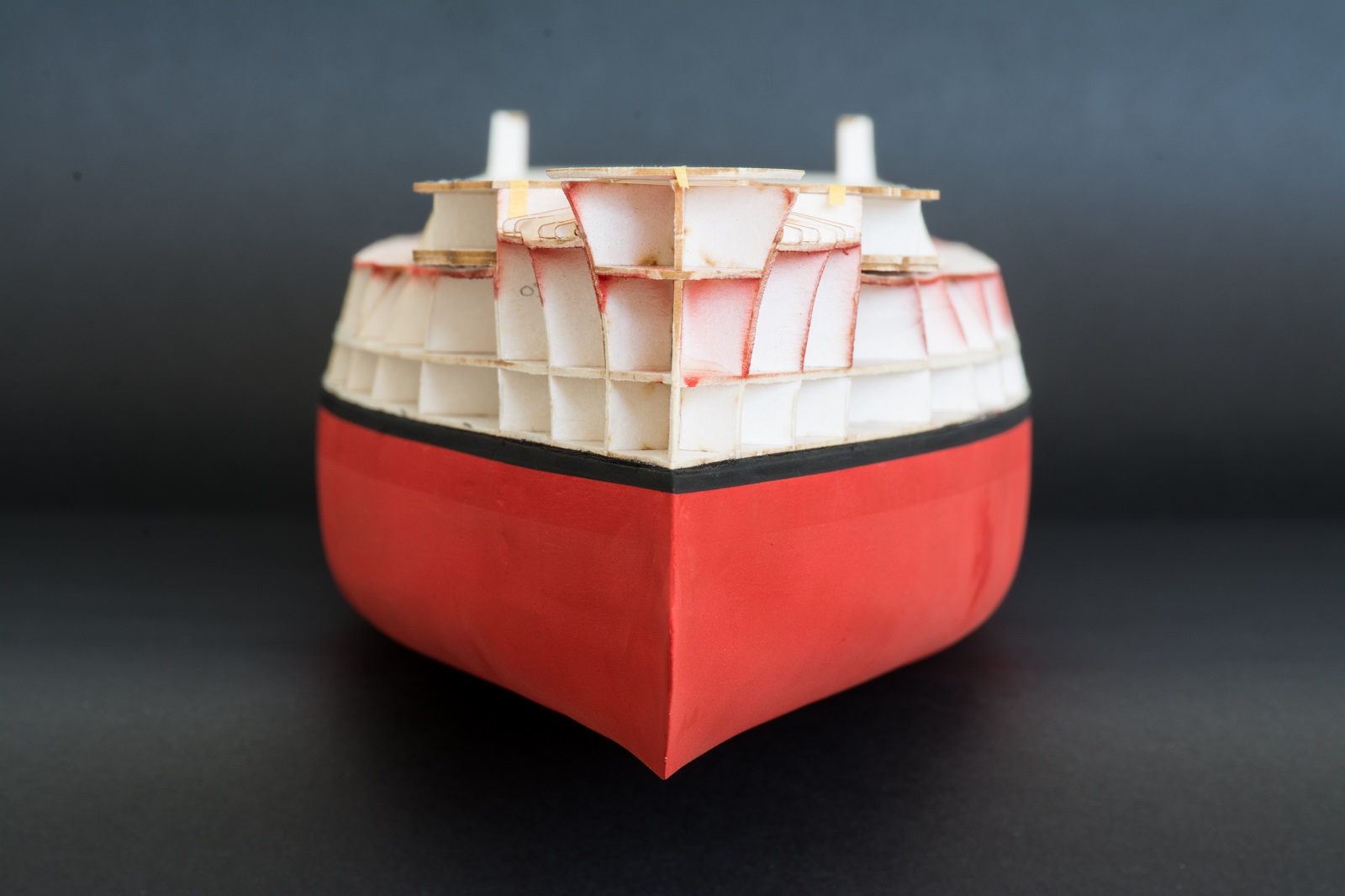
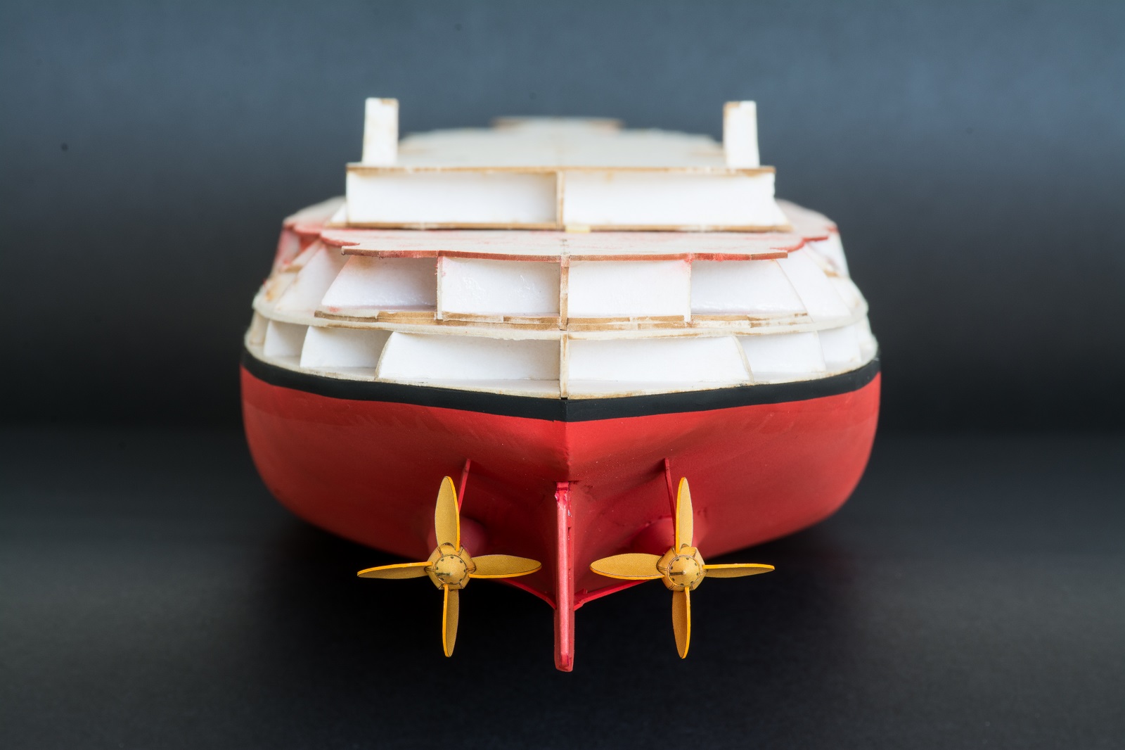
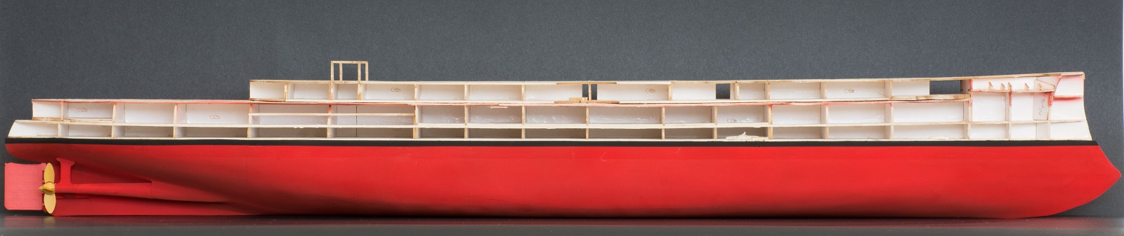
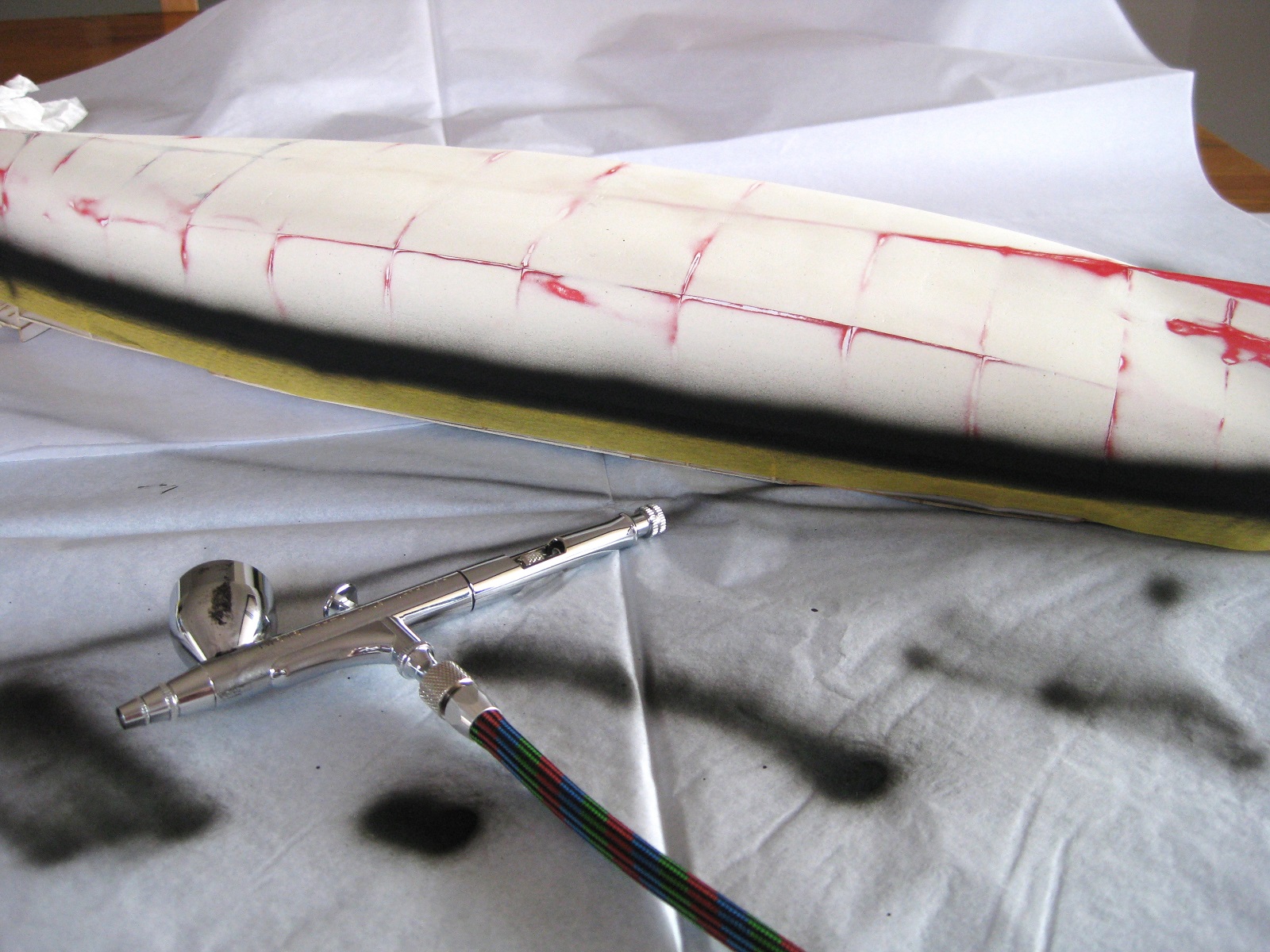
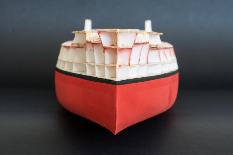
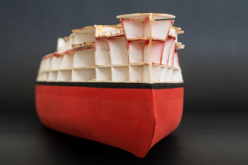
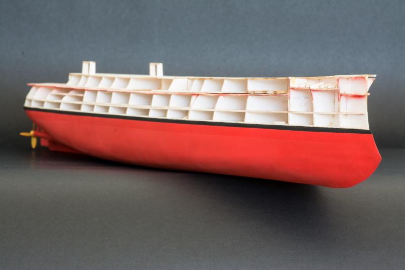
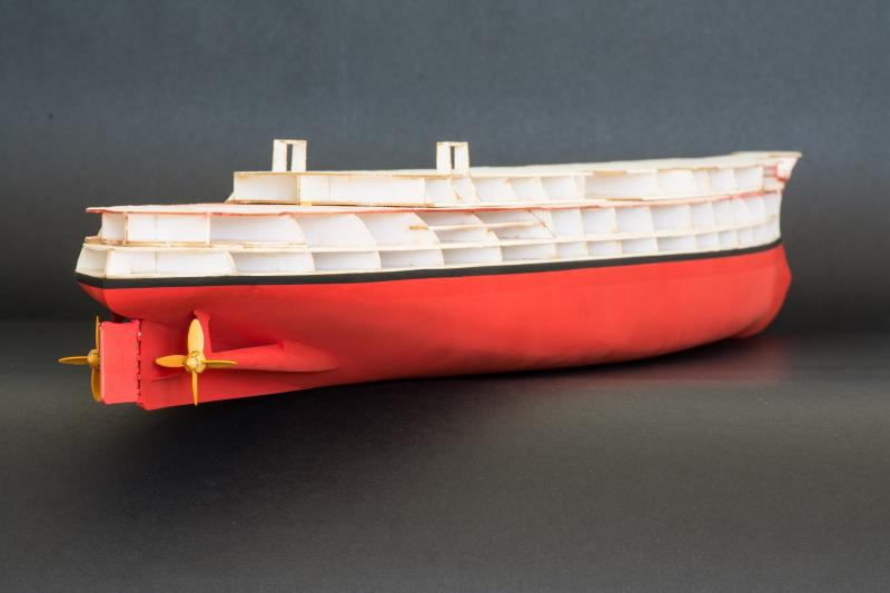
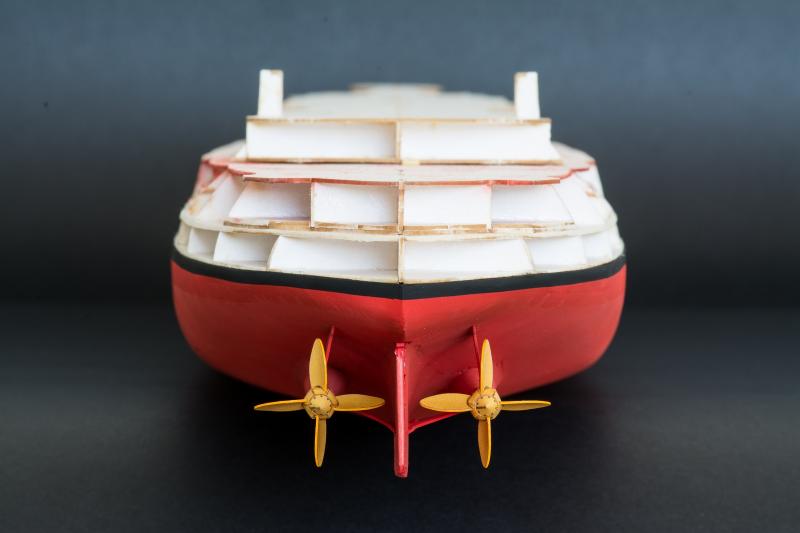
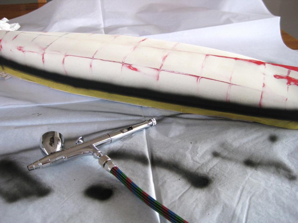
Hi All, Thanks for all the comments and likes. You may be on to something there Chris! I would imagine with your experience though lower hulls wouldn’t present too much of a problem. Thanks for dropping by Slowhand. There are plenty of warts to see coming up! LOL Thanks for the comment Brian. I am trying to avoid painting to gain experience trying to be as precise as possible. Okay on with the progress. My lack of painting experience really showed by doing the boot top first as per the previous post. I am sure the more experienced painters spotted the trouble with doing that. I had no idea how difficult it would be to cover black with red! I used Tamiya’s Flat Red acrylic XF-7 mixed at a 2:1 ratio and after spraying coat after coat of paint the black overspray was still showing through. Also patches of the grey filler putty I used were still evident. A plus point was that the boot top was very sharp and parallel and the red cover was very consistent, which is tricky using a small/medium size airbrush as the spray pattern isn’t that big for a largish hull…but I couldn’t live with it. A trip to the local hobby stored procured a can of Tamiya TS-27 Matt White spray paint and after masking off the upper sections of the hull, blasted on some decent coats of white. Got to say I find Tamiya’s aerosols very good, giving great coverage and pretty forgiving also. The white soon covered up the previous red and black airbrushing with a nice smooth even coat. It was back to airbrushing the complete lower hull again with the Red XF-7 and then masking off the 2.5mm boot top although this time I made it 3mm to make sure it covered the previous painting. Then the boot top was airbrushed in with Black XF-1. After peeling back the masking it turned out pretty good again. The red though isn’t as even and consistent as the first attempt but it is satisfactory to me. The lumps and bumps and filled areas are still evident in some sections but again thinking ahead and looking at the ship as a whole it shouldn’t look too out of place. I came to like the bright red paper printing of the hull and the Flat Red isn’t too far off it as can be seen with the unpainted rudder. I will paint and fit that permanently closer to the end of the build as it is too vulnerable at this stage. Similarly the props are only temporarily placed for the photos and will leave off to the end also. Here at last is the finished lower hull! I will give the whole thing a coat of Humbrol Matt Cote for protection and to flatten a couple of shiny areas where I accidentally splashed some thinners on it. With that saga out of the way I am looking forward to getting back to some real paper modelling again. Next up will be to line the anchor shelf so I can permanently fit the upper hull section, which will allow the decking, upper hull structures and side hull skins to be fitted. Cheers Slog

- 244 replies
-
- 18
-
-
- borodino
- dom bumagi
- (and 1 more)
-
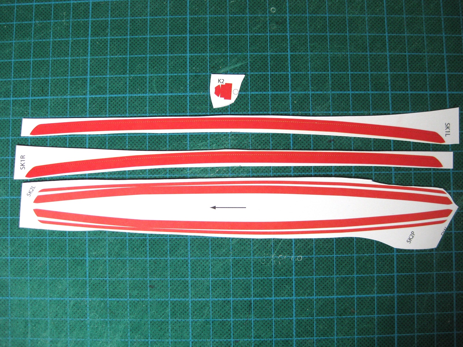
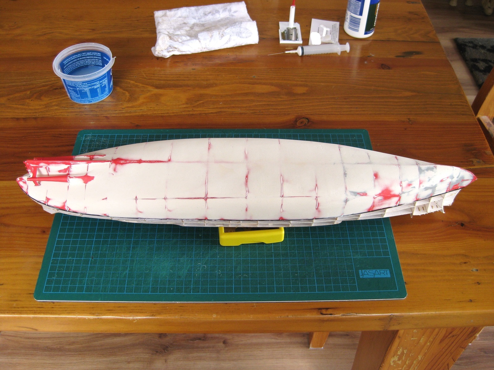
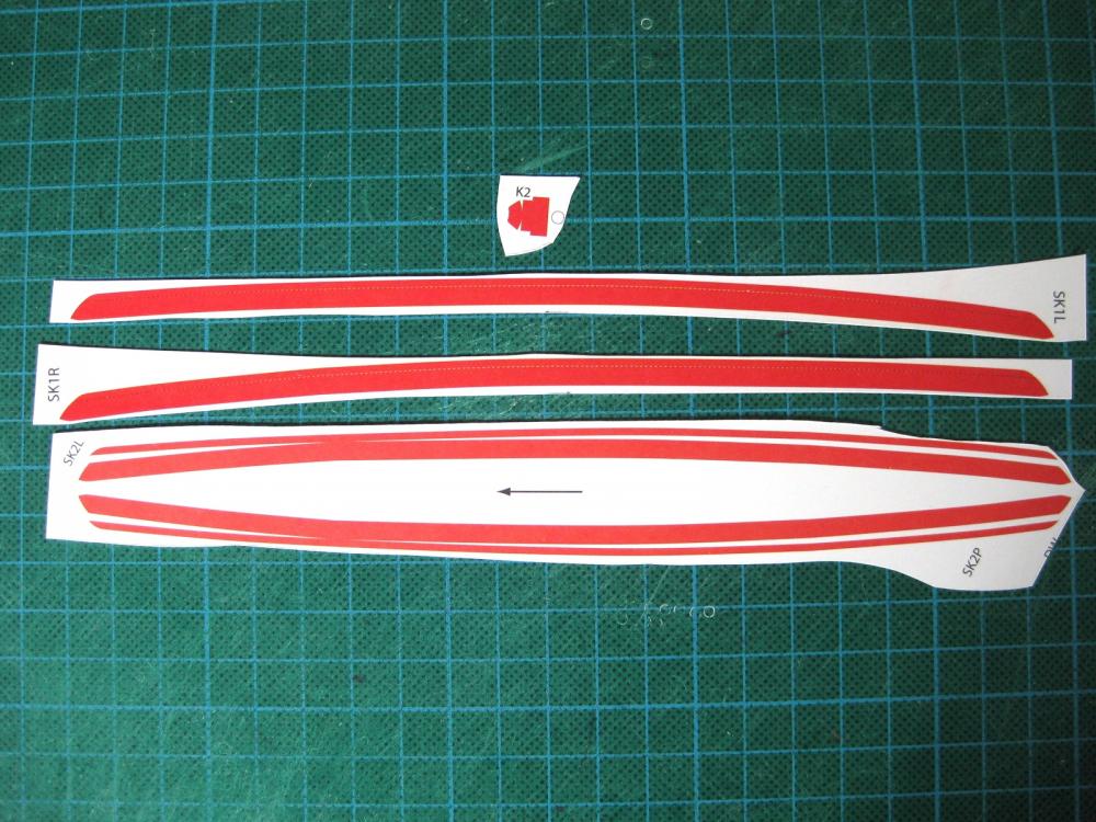
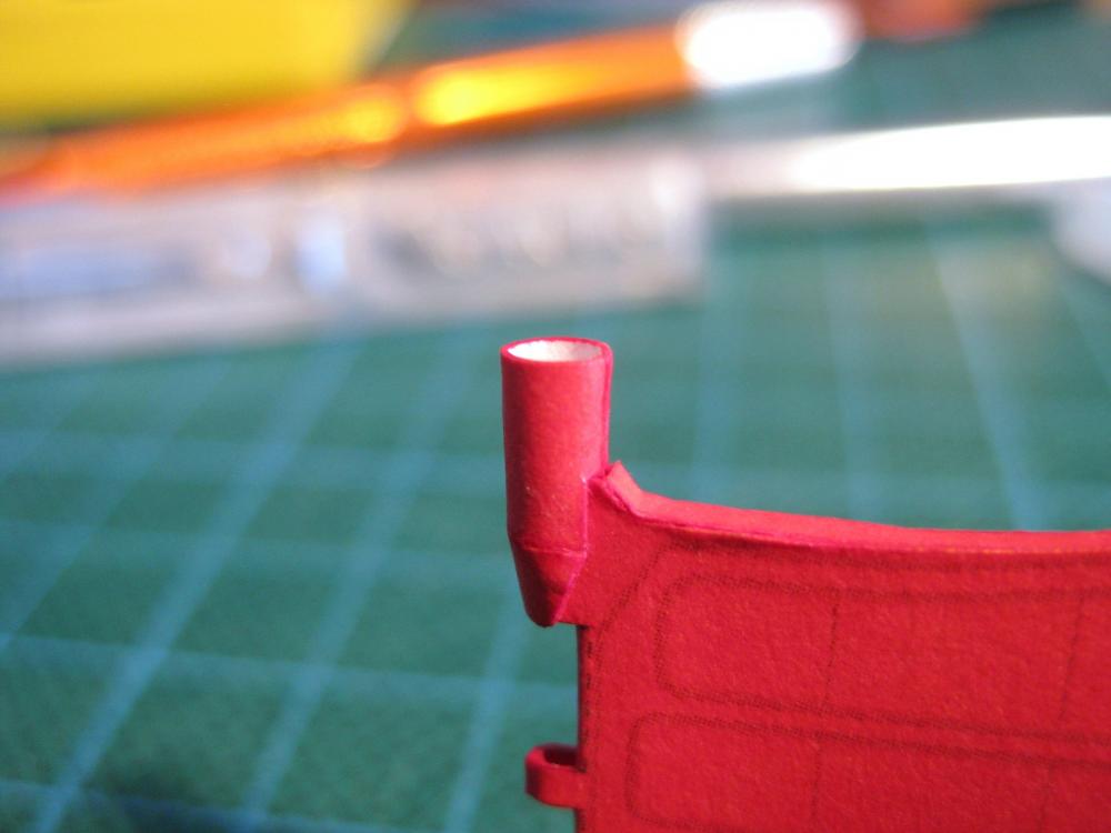
Hi All, A bit more progress, some wins, some losses and some draws. My modelling time lately has been very limited only managing to sneak in an hour here and there and most of that has been spent on the hull; which is taking its toll on both my enthusiasm and enjoyment. I’ll cover that below. The first photo covers the last of the lower hull attachments; these being the bilge keels and the rudder mount (part K2). The keels are in 2 halves with one side being full size with a dotted fold line along the top third of the keel. The corresponding part has a thin section and a lower section. The thin section is glued to the area above the dotted line and the larger section is joined only on the top edge. This forms a ‘Y’ shape with the top of the Y being glued to the hull. The first of the losses, my lack of experience totally messed up the first one I did. I didn’t do the second one although having one under my belt I reckon the second one would be more acceptable but decisions need to be made. 1. Carry on and have crap bilge keels on a so so hull 2 Make a new pair either with paper or Evergreen styrene 3 Forget them and continue on. I choose the 3rd option as need to get off the lower hull and back to paper modelling before I throw a wobbly. I may go back down the track and fabricate new ones but will see. I have accepted not having them on at this point. The small K2 rudder mount was formed with no problems. Being a combination of a tube and a cone I won’t go into detail as these were covered earlier. Posted the photo for no other reason than I had a win when it slipped over the rudder top perfectly. Okay here is the hull which has eaten into my limited modelling time for weeks now. First off the part alignment, size, fit etc of the skins were spot on and any issues were with me, so hats off to the publisher. Also surprising was the stern skins which I thought would be the hardest part with all the curves, slits and cuts turned out the easiest parts to fit. Secondly it was almost a given that I would end up filling and painting the lower hull and I accepted that and was happy enough to do. I am 2 for 2 for lower hull filling and painting LOL I have something else I will try for the 3 hull attempt before I turn to plastic models LOL Okay the skins were fitted, badly, and then given a brushed on coat of Humbrols Matt Cote to seal the surface and toughen it up a bit. What to use to fill in the hollows, dents and depressions? Plastic model filler should work…another loss. The model shop had run out of Tamiya putty but had the Humbrol equivalent. I don’t know if I got a bad tube or not but it would squeeze out nice grey smooth filler followed by spurts of black oily liquid so couldn’t get a good flow going. The stuff also went off so quick I didn’t have time to smooth and work it out and worse still it turned as hard as concrete. Fine I guess for hard plastic not so good for flexible paper <sigh> Okay not using plasterers seam putty again as per the Bismarck as it has far too much moisture in it so tried Polycell skim filler. This worked okay but still has a fair bit of moisture so some buckling did occur but dried back again okay. Spread it on in multiple thin layers, building up the surface before sanding. Of course it sands really well. After sanding and blowing and brushing off the dust I continued to skim on more filler before sanding again. After doing this like 3 times and each time thinking it was spot on I would come back to it at a different time of day and a different light and see a whole new range of marks etc really put the dampeners on my mood. I had to take stock and assess what I am really trying to achieve here. Am I after a smooth flawless hull like a plastic model from a paper and plaster material or am I trying to get my initial muck-up into a presentable state to continue? I jumped on line and checked out some completed paper models I really admire and whose hulls have been applied flawlessly without resorting to remedial work and guess what, although perfect they still had a particular look to them associated with paper models. That was the decider for me, I want to paper model not body work! So another coat of Humbrol Matt Cote was brushed on followed by fitting the prop shaft fairings and the supports from the previous post. Because of my body work I had to trim the supports slightly but no issues. After all my hard work with the prop tubes they are totally hidden once the props go on LOL. Typical, my best work is fully hidden and my worst is on full view to the world! The lower hull end is insight. I masked up the edges of the upper hull where upper hull skins fit but didn’t bother fully covering the upper area as nothing to be affected by over spray. I know I should paint the lighter red hull before doing the black boot top but I have a plan to make masking the boot top easier so did that first. Got the airbrush out for the first time in I don’t know how many years and mixed up Tamiya Flat Black acrylic at a 2:1 paint to thinners ratio and sprayed at around the 15 psi mark. It sprayed beautifully with this set up. I am hoping I can get the red done tomorrow but will see. I know this post sounds like a long winded whinge and whine and that I am down but I just need to cut, fold, glue, bend, whatever, some paper not endless body work. Again even that wouldn’t be so bad if I had stacks of free time but I am so close to getting back at it I can taste it Lol Cheers Slog

- 244 replies
-
- 12
-
-
- borodino
- dom bumagi
- (and 1 more)