shipmodel
-
Posts
941 -
Joined
-
Last visited
Content Type
Profiles
Forums
Gallery
Events
Everything posted by shipmodel
-
 Hi Marc - If I understand your problem, there is a geometric solution using a fan-shaped set of lines. I would love to include a drawing, but I don't have access to my library, and I am stumped, at the moment for its name (another senior moment). I am sure that it appears in either Roberts' or Dressel's books on planking. Maybe you already know the trick. If so, ignore this. Here is how I make it, sorry if it's a little long. On graph paper I draw an X-Y pair of lines with their intersection toward the left of the page. I draw another vertical line set some convenient distance away to the right. On the vertical line I make equidistant marks up to as many, or more, than the planks I expect to need. A set of lines from the intersection go to each one of these, making a fan shape. Now any similar vertical line will cross those fan lines an equidistant space from each other, no matter how tall or short. Lay a strip of paper on the fan and mark off the divisions that match the space you want to fill and the number of planks you want. Lay the strip on the deck athwartships and mark out your plank widths. As a possible addition, increase the space for the king plank location on that initial vertical and it will always be proportional to the planks. I have not done this and it may not end up looking like you want. If you are still doing research, you should look for 'coamings' rather than 'combings'. They sound alike, but are very different animals. Stay safe and well. Dan
- 2,699 replies
-
- 4
-

-
- heller
- soleil royal
- (and 9 more)
-
I'm with Druxey on this. In fact, when carving a figure, either human or animal, I start with the eyes. Nothing sets the tone and realism like them. If I get the eyes wrong, I always discard the piece. Dan
- 2,699 replies
-
- 6
-
-
- heller
- soleil royal
- (and 9 more)
-
Thanks, Marc - This is a really useful tutorial on miniature carving and should improve the work of everyone who reads it. Looking forward to seeing how all your many intricate carvings come out. Dan
- 2,699 replies
-
- 3
-
-
- heller
- soleil royal
- (and 9 more)
-
Ron - There is a strong epoxy called JB Weld that I use when I need a strong rigid joint with only a small mating surface. If you can't make a safe trip to the hardware store, I am sure it is available on line. Best of success with a tricky problem. Dan
-
Ron - You have my most sincere sympathies. Been there, done that, - - thrown the results across the room . . . I saw in an earlier photo that you are using a mini-torch to do the heating. I never liked the one I have. Like you, I had a lot of trouble localizing the melting. Now I use either a resistance soldering unit (Cold Heat) or a small soldering iron used for the electronics industry. It takes a bit longer, but I have much more control over where the heat is and where it isn't. A wet piece of folded paper towel is all I ever need to keep the heat from travelling too far. Best of success. Dan
-
Hi Marc - Happy to be of some small help. The wood is, if I remember, apple. I used to use a handheld drill as a lathe before I got the benchtop drill press. I set up a piece of wood with a conic depression in it to steady the free end of the dowel as it turned. This does require that either the drill or the wood, or both, need to be clamped in place. Or you will need three hands. Dan
- 2,699 replies
-
- 7
-
-
- heller
- soleil royal
- (and 9 more)
-
Hi JD - She looks like a sweet boat. I will definitely be following along. Dan
-
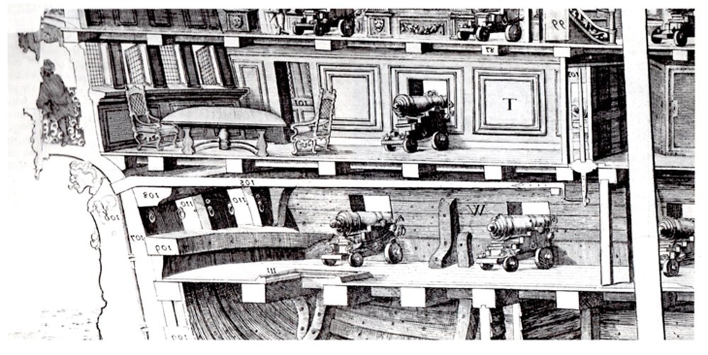
Thanks to all who contributed to this interesting discussion of the whipstaff. I thought I was pretty well versed in its intricacies, but even so I have learned a lot. At the end, I have to agree with Druxey and Dafi that any slot in an upper deck, if needed, would be fairly short. It could be covered, railed, or even with a hood. The one reasonable certainty seems to be that a long slot, as drawn by Leminuer or Budriot, would not be needed. As far as contemporary cutaway drawings go, they are so varied and all over the place that only very general conclusions can be drawn. For example, below is one which my notes identify only as "Phillips - 1690s" It has a very short staff that does not pierce the upper deck at all. Others show the mizzen mast being stepped on the deck above, with the tiller passing under it and extending forward to meet the whipstaff. In that case the pilot's view and communication would not be hampered as much, but the mast might not be as stable. As with many of these issues, I think that shipwrights experimented with various solutions in different ships, so there is probably no one clear 'right' answer. Of course, I could also be completely wrong. 😕 Thanks again, and stay healthy. Dan
- 2,699 replies
-
- 7
-
-
- heller
- soleil royal
- (and 9 more)
-
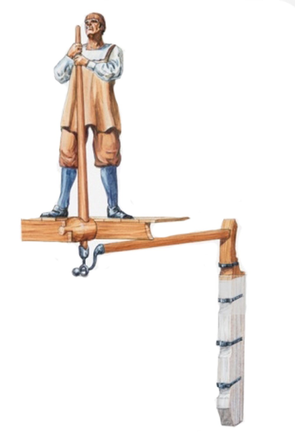
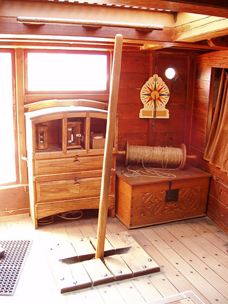
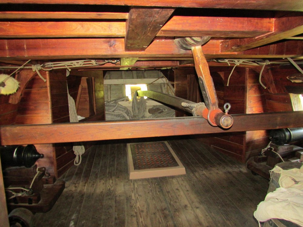
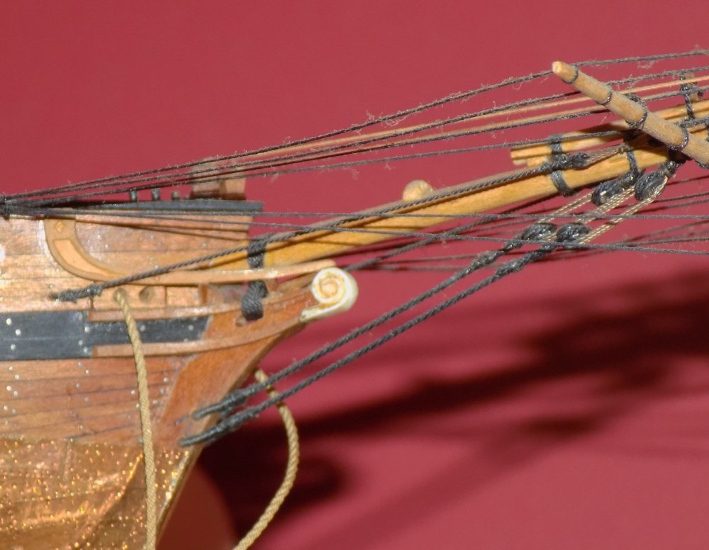
Hi Dafi - Your point is well taken. In a large ship or in rough seas it may have been necessary to have more than one handler (helmsman, pilot) for the whipstaff, and a longer staff would give room for them to work together. In my illustration I took the drawing from Goodwin just to show how the head of the staff moves in as much as it moves down, I did not really consider overall length other than to question the need for a long slot in the deck above. As for length, below is a photo of the top of the staff for the Susan Constant, which matches the below deck picture from my earlier post. I know that she was a much smaller ship, but the staff only looks to be 5 or 6 feet long. This agrees with photos of whipstaffs from other recreations, Batavia, Kalmar Nykel, and Mayflower. I have a photo of the highly elaborate rowle from the much larger Vasa, but not the top of the staff, so I can't say how long it was. Perhaps someone knows. As far as the William Rex model - with all respect to the modeler, he has the staff coming up through a simple hole in the deck above, which is unworkable. Dan
- 2,699 replies
-
- 5
-
-
- heller
- soleil royal
- (and 9 more)
-
Jan - I think we are agreeing in different words. The overlength staff doesn't give more leverage, since the force applied by the helmsman is all athwartships due to the rotation of the rowle on its fore/aft axis. He pushes the head of the tiller to the side by sliding the staff through the rowle, he does not lever it aside. The mechanical advantage is gained by the ratio between the length of the tiller and the width of the rudder. Nor is a longer staff needed to enlarge the arc that the tiller head travels. The swing of the tiller arm is limited by the length of the metal crook or the end of the tiller that the ring on the base of the whipstaff slides down as the helm is put over. When the ring reaches the end button no further movement is possible. The lower photo is from the Susan Constant reconstruction. I went to Google and searched for William Rex. I found many images for the very large model in the Rijksmuseum, but none of the deck with a slot in it. Can you point me to a photo? Thanks Dan

- 2,699 replies
-
- 5
-
-
- heller
- soleil royal
- (and 9 more)
-
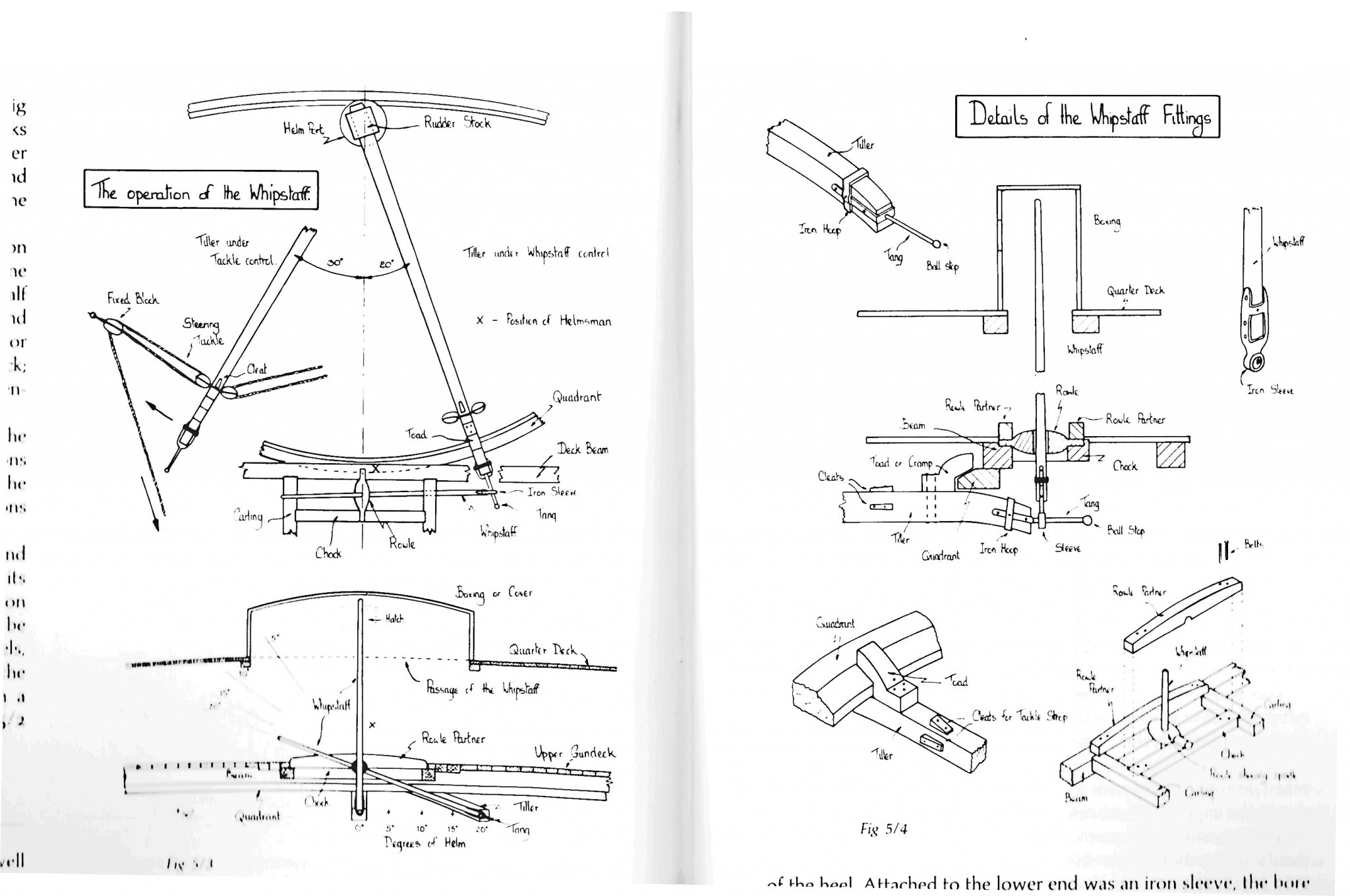
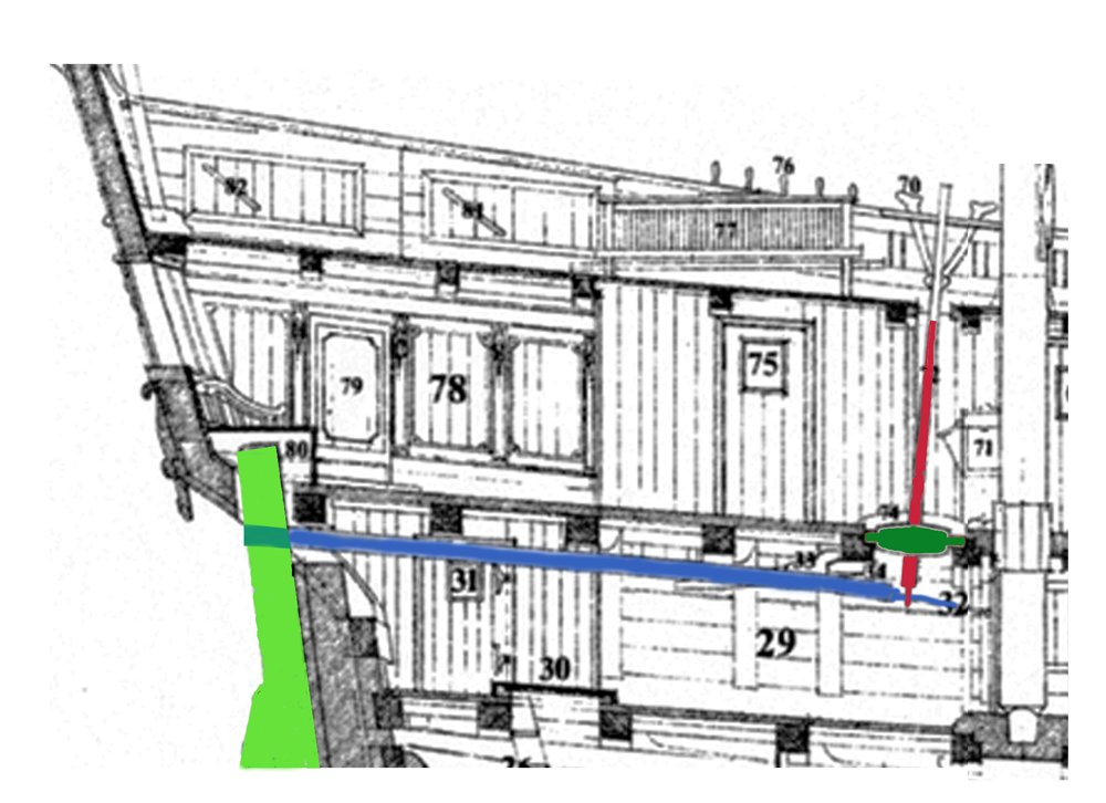
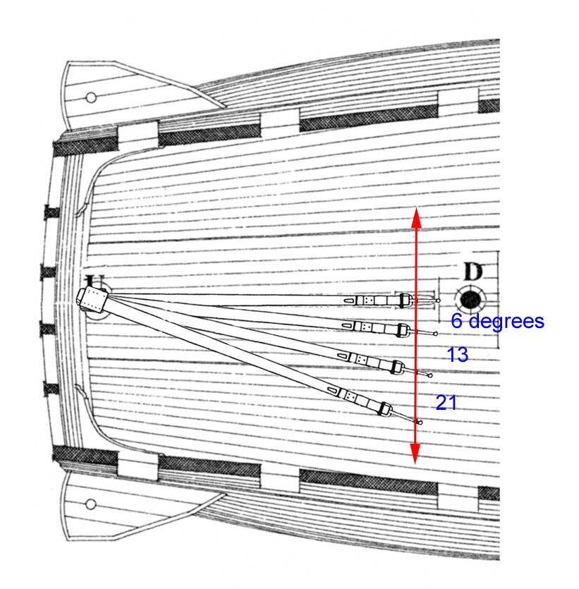
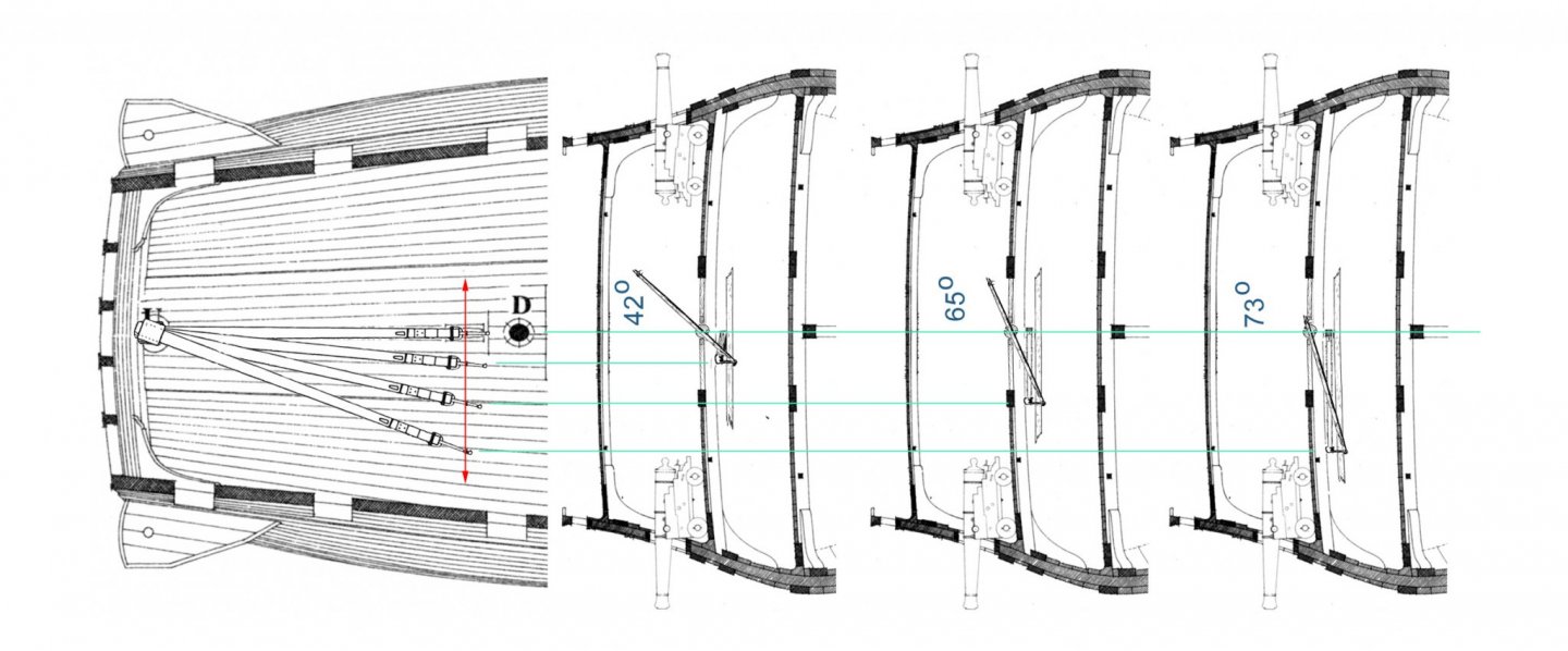
Hi Marc - The whipstaff question is one that I worked on for a while. I have never been happy with the long slot in the deck above (#97 in your illustration). It would weaken the deck and introduce a tripping hazard. If there is such a slot on a contemporary model I have not seen it. Moreover, it is, I believe, completely unnecessary. Here's why - I took contemporary illustrations as well as the measured drawing from Goodwin's "Arming and Fitting". Then I took out various parts using Photoshop and laid them in various positions to see how they related to each other as the whipstaff pivoted, the tiller arm swung, and the rudder turned. Notice that, as you can see in the Goodwin drawing, the whipstaff is not fixed to the rowle that it pivots in, but it slides through the hole in the rowle so it can reach the end of the tiller arm as it swings side to side. This is the key to my thinking. I took the plan view and superimposed the drawing of the tiller arm in various positions, offset 6, 13 and 21 degrees from center. (Although I have read that in practice the rudder would not be deflected more than about 15 degrees. After that it loses its grip on the water.) I combined this layout with the cross section view of the whipstaff stave and decks. In use, as the tiller arm swings, its end moves further and further from the rowle, requiring that more and more of the whipstaff slides through the hole in the rowle, shortening the length above the rowle. In almost all positions other than perfectly upright it does not extend up to, much less through, the deck above. So rather than a long, dangerous, slot in the deck above, all that is needed is a little opening, like the hood pictured in the Goodwin drawing. This has the added advantage of bringing the helmsman's head up one deck for easier communications and so he can see the set of the sails as they draw. It keeps his body down near the rowle so he can manage the staff as it lengthens and shortens as it pivots and slides. No slot required. Thoughts? Dan

- 2,699 replies
-
- 5
-
-
- heller
- soleil royal
- (and 9 more)
-
JD - Beautiful work on the Pride. You should be very proud . . . The rigging is especially impressive.. For only a 2 page build log yours was excellent. Informative and engaging at the same time. Well done. Stay healthy Dan
- 60 replies
-
- 1
-
-
- pride of baltimore ii
- Model Shipways
- (and 1 more)
-
Marc - So sorry to hear that it got you, but glad you are not in the target population and should be OK. Joyce and I send our best wishes and we will see you at the next club meeting, whenever it is. Get well speedily and completely. And stay away from me !!! Dan
- 2,699 replies
-
- 6
-
-
- heller
- soleil royal
- (and 9 more)
-
Ron - They came out beautifully. Well done. Dan
-
A very nice 'Dutchman' repair. Once the shrouds and stays are tensioned, there shouldn't be a lot of strain here anyway. Dan
- 2,699 replies
-
- 5
-
-
- heller
- soleil royal
- (and 9 more)
-
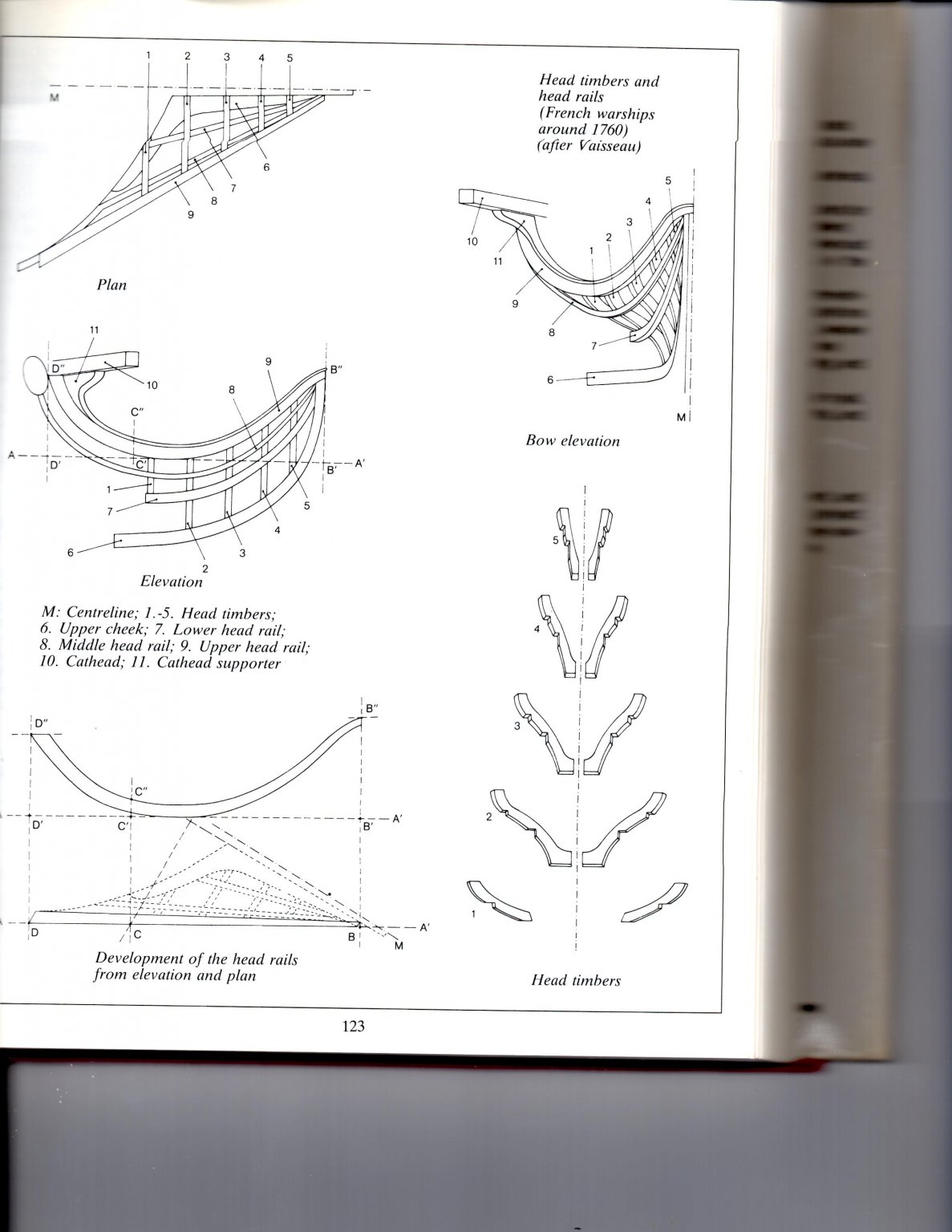
Hi Ron - Just checked in and found you struggling with the headrails. Don't worry, we have all been there. But you may be making more work than needed. The head timbers do not straddle the stem, but are separate pieces to each side. Here is a page from zu Mondfeld's "Historic Ship Models". You can see in the lower right that they are paired support pieces and do not connect to each other. In this configuration you can make them separately to match what may be some slight variation in the headrails on either side. I cut the head timbers to fit the headrails instead of trying to match the headrails to the head timbers. I think this is an easier sequence. That said, in this little area under the bowsprit they will be difficult for anyone to see, so you can keep the ones you have with little down side. Hope that helps, and I apologize if it makes things worse. Best of success. Dan

-
Hi Marc - What model was that in your photo. I would like to take a tour. Dan
- 2,699 replies
-
- 3
-
-
- heller
- soleil royal
- (and 9 more)
-
Hi Marc - Really nice work on the rudder. It will be almost overlooked in the finished diorama, but your dedication to detail will shine through to those who know. I have had a lot of success painting with the tiny metal tools that fingernail painters use. Not very expensive online. I would go with the epoxy. I find that cyano heats as it cures and could warp the plastic masts. I think of epoxy as being more flexible too. Be well - you and your entire family. Dan
- 2,699 replies
-
- 3
-
-
- heller
- soleil royal
- (and 9 more)
-
Hi Ron - For cleaning out and smoothing miniature carvings, I have found nothing better than a good set of rifflers - curved needle files. She is coming along very nicely. Be well Dan
-
Hi Mark - So glad you are recovering from the aftereffects of your stroke. I know that it will take time, but mental exercises like model building can make the process as speedy and complete as possible. You have best wishes from me and, I am sure, the entire ModelShipWorld community. When you have a moment, I would love to see your helicopter. Be well Dan
-
Hi Mike - I agree with the others that you are doing a great job with the restoration. That's the good news. The bad news is that it is not likely that you will ever be paid a reasonable return for your work. Having done dozens of restorations, the most important commercial fact I have learned is that once the model is repaired, the repair cost is folded into the value of the model. Imagine that you have a wrecked 1975 Dodge Charger. You spend $10,000 worth of time and money fixing it back up. It then becomes just another used car worth about $6,500. Most times, unless the model itself is of high intrinsic value like a bone and ivory POW model, the repair will not pay for itself. Your model is a very nice example of an ocean liner model. But it has some simplistic details and is not a model of a famous ship. At this point in my career I do not repair models without a firm contract for the repair work itself. I leave any subsequent sale to the client. I'm happy to discuss this further if you contact me at shipmodel@aol.com or phone at 718-855-1720 You can even come to the next meeting of the New York Shipcraft Guild in downtown Brooklyn next Tuesday, March 10. Contact me for the details if you are interested. Sorry to be the bearer of unwanted news Be.st of success to you. Dan
- 27 replies
-
- 6
-
-
- queen frederica
- cruise ship
- (and 3 more)
-
Marc - Hubac's Humble Historian as always. Your work is much more than simply 'quite good.' Impressive, imposing, inspirational, and other words beginning with 'i' are much closer to the incredibly high bar that you have set for yourself and everyone else. Thank you for sharing it with us. Dan
- 2,699 replies
-
- 5
-
-
- heller
- soleil royal
- (and 9 more)
-
Hi Ron - As always, I truly admire your perseverance, commitment, and craftsmanship. Please keep up the great work. Your carving of the scroll is beautiful, clean and crisp. I tried a complicated headpiece on my Oneida, but couldn't carve small enough to do it. I ended up just using a simple volute scroll. In any event, since she was built in the small undeveloped hamlet of Sackett's Harbor, and in a hurry to launch before the British, I'm not sure that she would have had anything complex. That's my story and I'm sticking to it. Dan
-
I should have known that your eagle eye would have spotted the curiosity already. Be well
-
Hi David - I was wondering what you were working on. Now I see, and seeing is believing just how excellent is the work you and Greg are executing. The framing is clean and precise, the carvings are artistic gems. I have signed up for a front row seat and have a full bucket of popcorn. One question - how will the anchor cable lead outboard with the hawse piece set that high? It looks like the aftmost support between the headrails will be in serious danger if the ship swings at anchor. It is probably the angle of the photograph, but it did catch my eye. See you in New London, if not before. Dan