


CPDDET
-
Posts
1,135 -
Joined
-
Last visited
Content Type
Profiles
Forums
Gallery
Events
Posts posted by CPDDET
-
-
2 minutes ago, Overworked724 said:
Awesome work, Dave!
Thanks, Pat!
-
That's a real compliment coming from someone with your skills. Thanks!
-
I took the plunge some time ago and purchased a set of 3 pin vices from Starrett and never looked back. Not cheap but a quality tool.
- toms10, turangi, thibaultron and 3 others
-
 6
6
-
First off I have to thank Richard (AKA retiredguy) for his help and guidance in fashioning these bilge pumps. He has been more than generous in answering my question and providing assistance. As long as these took to build, it would have taken much longer and a lot more *#!?**#! without his help.
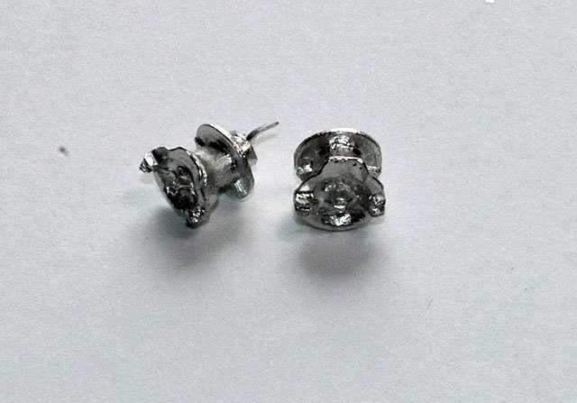
Here is a pic of the pumps that came with the kit.
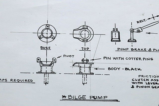
And here is the plan drawing of the pumps
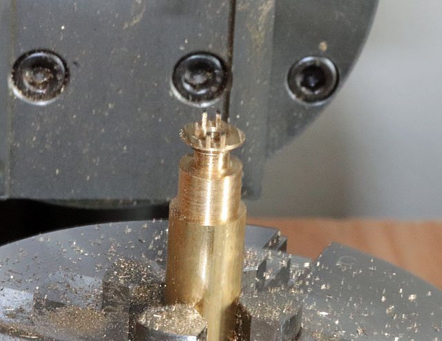
Starting with a 3/8 round brass stock on the lathe I turned it down to .306 inches. Painted the surface with a black marker and scribed the different areas that needed to be fashioned.
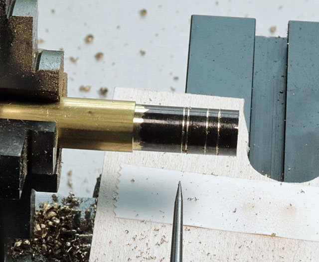
Still on the lathe I made the first cut .081 inches from the face of the piece and turned the stock down to .205 for .148 inches. Then moved .136 inches from the face and turned down to .171 inches for .093 inches. This fashioned the body of the pump. I used a #5 drill bit to create the “bowl” and a #29 drill bit to make the hole for the plunger.
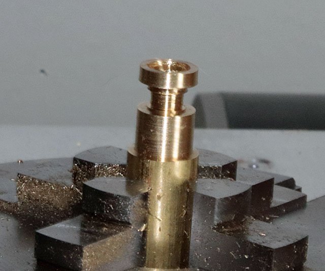
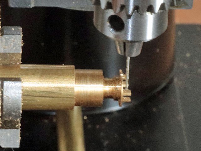
Then moved to the mill. I used a 3/64 inch end mill to cut the space between the 2 “ears” and then removed the unwanted material to form all 4 “ears”.
Putting the chuck on a right angle bracket, I used a #76 drill bit to make the holes through the “ears”. This should be the right size for the .6 mm bolts I plan to use.
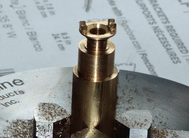
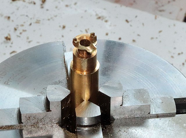
This is the piece after turning and milling.
I used a 5/32 end mill to create a half circle cut for the spout and used .010 thick brass to fashion the spout. I soldered the spout in place and did some filing to shape it.
So here are the 2 bilge pumps with the spouts. And while they aren’t perfect, I believe they are a big improvement of the white metal ones that came with the kit.
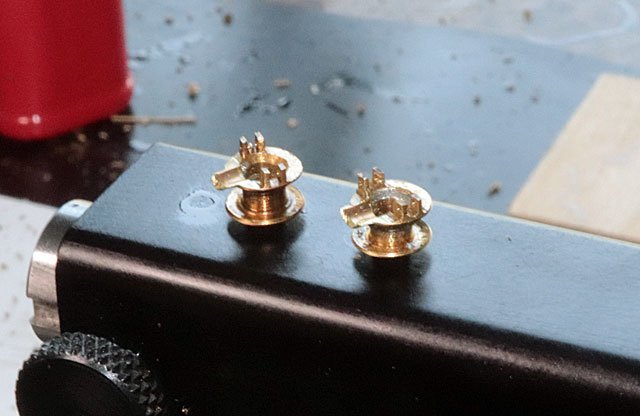
Now I will attempt to build the plungers and linkage, don’t hold your breath for the next update as this may take me awhile.
- Duanelaker, Schooners, GrandpaPhil and 2 others
-
5
-
1 minute ago, allanyed said:
Depending on where you are located some storage units have climate control. Down here in SW FL, there are a good number of them.
Allan
Learn something new every day!
- mtaylor, Canute and thibaultron
-
3
-
How would one control temp and humidity in a storage unit?
- Canute and thibaultron
-
2
-
Thanks Gagliano, your kind comments are much appreciated. But I'm still new to this hobby and trying to learn. I'm finding that each step is a build in its own right. I still struggle with the "how" to build things. I really have to slow down, think things through and ask for help before proceeding. And even then i end up remaking a part. I'm finding the bilge pumps a challenge and moving slowly on them. But it's not a hobby if we have to rush, right?
-
13 hours ago, Overworked724 said:
Bingo!!!! And since I don’t have a mill or a lathe, modeling with the sculpy gave me an opportunity for realistic illusion. Might not be wood or metal, but I think it looks pretty bloody good for a first attempts at catheads with sheaves (sans lathe).
By the way…I’ll give all the credit to my knowledge and fearless attempts at ridiculous but fun uses of this stuff to Chuck since he used this stuff in his Sultana Practicum (my first and only build). 👍🏽

And having a multitude of ways of skinning a cat makes for a great workshop.
-
Possible. And if one had a lathe they could be made with that. But using sculpy is a pretty neat way to do it.
-
Keep us posted as I'm sure I will be using it sometime in the future.
-
Never used sculpy but wondered if one could pack it into an appropriate sized brass tube, then push it out with a dowel rod and bake. Might result in perfectly round rod? Just a thought, didn't mean to stick my nose into your more than capable build techniques.
-
24 minutes ago, Nirvana said:
Nicely done! I am doing the racing version too, and again the "bilge pump" made out of white metal are ugly. Looking forward to see what you are coming up with.
Haven't decided on full or furled sails.
While I'm far from it, I'm thinking furled sails at this point.
-
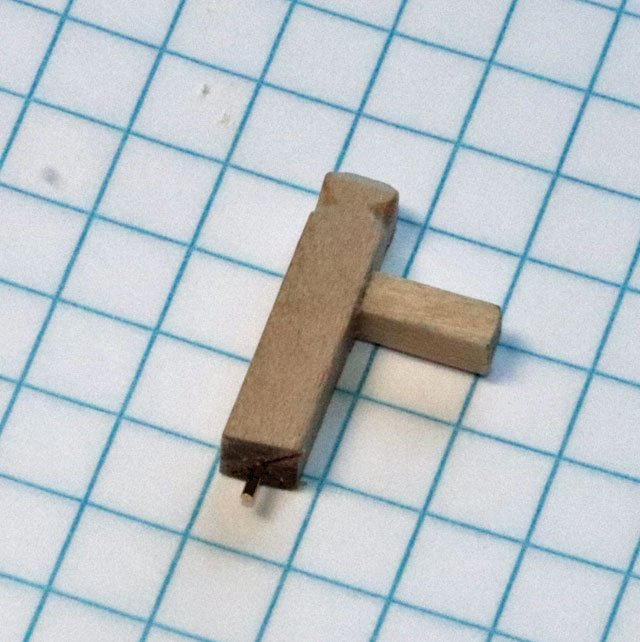
I started the samson post assembly by first fashioning the main post and the support for the brake beam. Cut the bottom of the post to fit the deck angle and added a small wire pin to help secure it to the deck
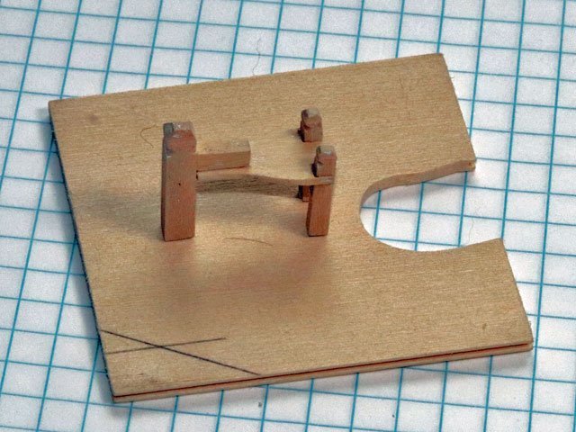
Completed the rest of the assembly using some laser cut parts that came with the kit and some scratch built parts.
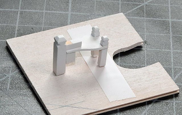
Mounted the finished assembly on a scrap piece of wood, using the pin in the base of the main post and some double stick tape for the smaller posts. After taping off a spot to mount the brake beam I air brushed the piece.
Added the brake beam and pawl and glued the assembly in place. Added the windlass, counter shaft and jumbo jib boom crutch. Still have to attach the 2 ends of the brake beam to the 2 ratchet quadrants. Not sure if I will use wire or thread coated with clear matt nail polish.
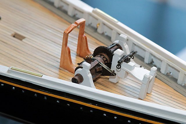
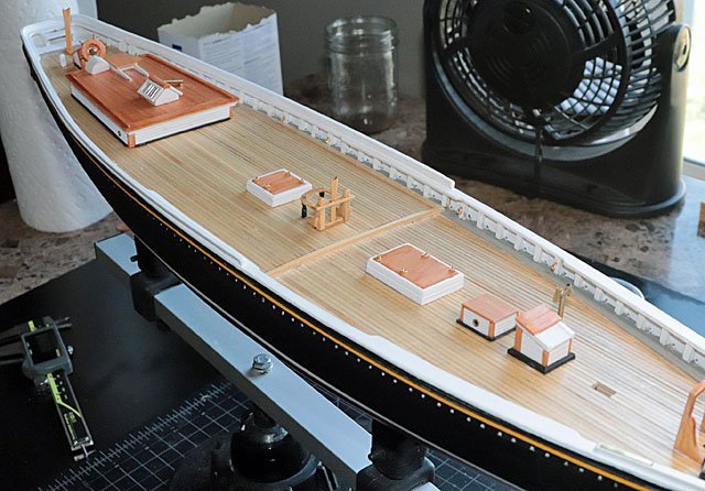
That completes 99% of the deck furniture. You may notice that there are some gear assemblies near the jumbo jib boom crutch missing as well as an engine box and linkage. But I’m building the racing version and the plans state these items were removed from the deck when racing, probably to reduce weight (especially forward weight) and to lessen the chances of fouling lines during head sail changes / tacking.
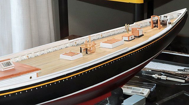
Now it’s on to attempt making my own bilge pumps and another boom sheet buffer.
- PRS, GrandpaPhil, Duanelaker and 2 others
-
5
-
I've found there isn't one " do it all" tool for any building process. No matter if your cutting, shaping, sawing or whatever, it takes multiple tools that do the same job in different ways. I have standard tweezers, cross lock and forceps and find them all useful at the proper time.
- mtaylor, allanyed, Roger Pellett and 4 others
-
7
-
Always good to have a plan.
-
Excellent craftsmanship, Pat. Looks really nice!
Dave
-
According to the plans, the ratchet quadrant should fit over the ratchet gear on the windlass. The windlass ratchet gear is clad on both sides with a solid disk and ratchet teeth extend a bit beyond the edge of these disks. It took me awhile to come up with an easy way to achieve the proper fit of the quadrant over the ratchet gear.
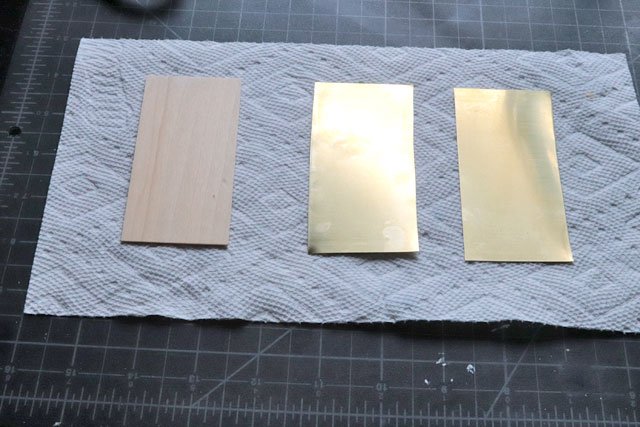
I sandwiched a 3/64 piece of basswood between 2 pieces of .010 brass sheets. The brass was easily cut with scissors and I made the pieces big enough to handle when done. This created a lot of scrap but made things much easier. At the end of the process the wood core could be filed out just a bit so that the brass outside pieces would fit over the teeth of the ratchet gear.
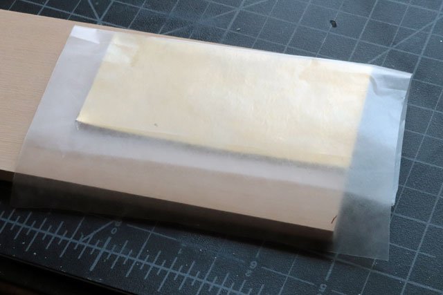
Gluing the three pieces together, I wrapped them with wax paper.
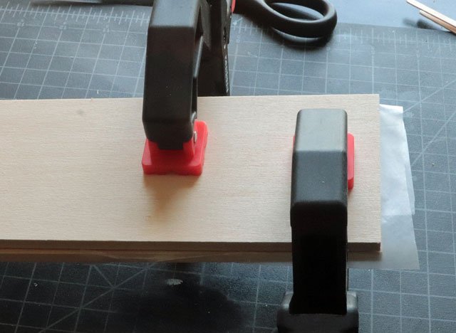
Then clamped them between 2 pieces of ¼ inch basswood and let dry.
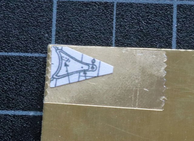
After making a copy of the plan I cut out a picture of the quadrant and taped it to the sandwiched plate.
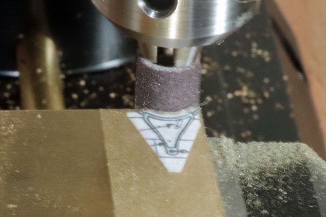
Using a ¼ inch Dremel sanding disk mounted in the mill, I formed the curve of the quadrant.
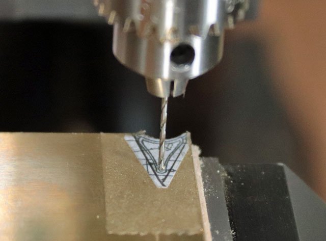
While sill mounted in on the mill, I drilled out the hole which will be needed for the linkage to connect it to the brake beam.
Using my WeCheer rotary tool and a separating disk I cut the quadrant from the sandwiched plate.
This is the finished quadrant of which I made two.
After cleaning up the brass I blackened with Casey Brass Black and added the rings for the linkage.
Now I can finish building the Sampson post and install the linkage between the quadrants and brake beam.
-
-
-
Sorry it’s been so long since I posted and update. But sometimes life just gets busy and priorities change. Anyway I finally finished the Brake Beam.
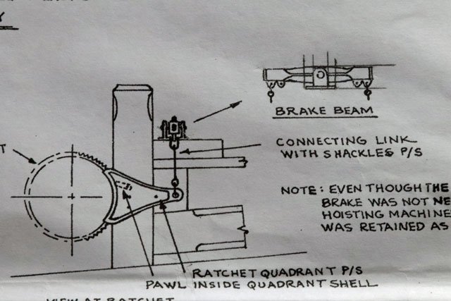
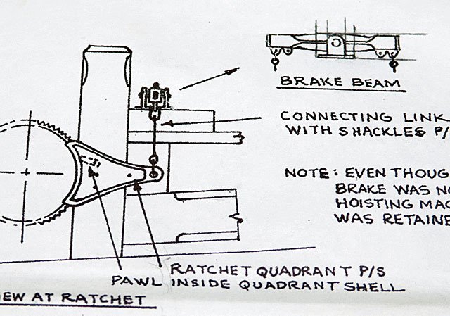
This is a photo of the plans with the Brake Beam in the upper left.
This is the ugly white metal part that came with the kit. I found it totally unacceptable and decided to make my own.
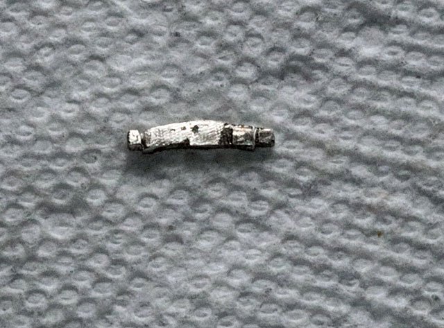
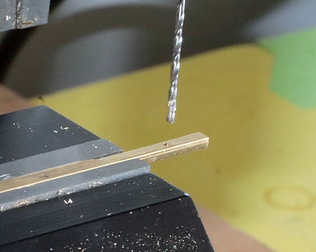
Unfortunately I didn’t do a very good job of documenting my process with photos, although I did take a few. Sometimes I get so involved in the build process I forget to pick up the camera.
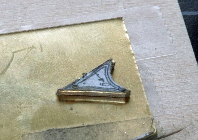
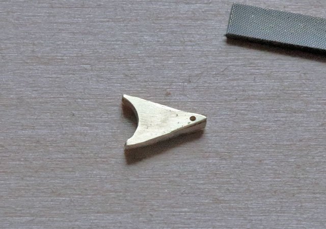
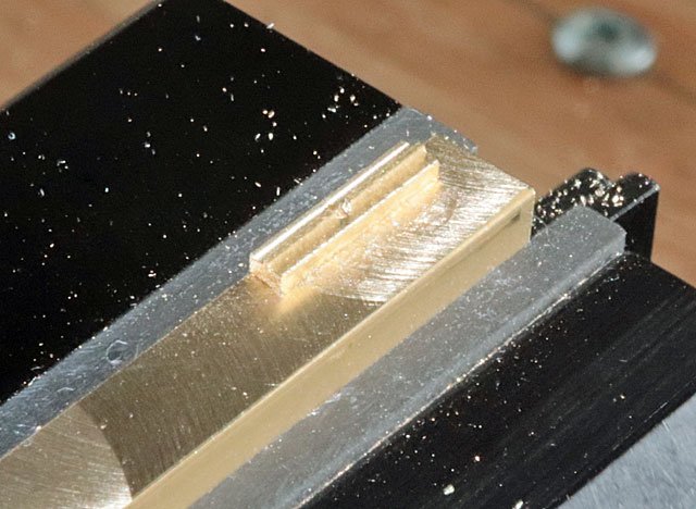
Following is a few photos of the milling process.
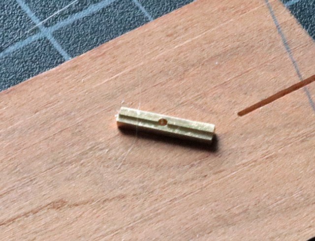
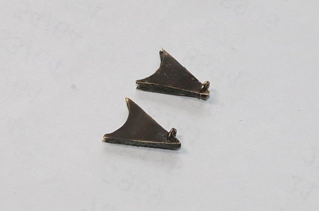
After filing to shape I added some square brass tube to the ends of the arm and the small pieces below them.
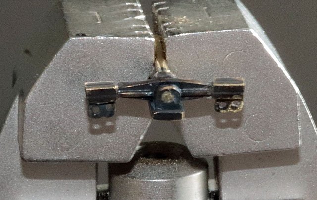
Then added the rings that will be part of the connecting links to the Ratchet Quadrants.
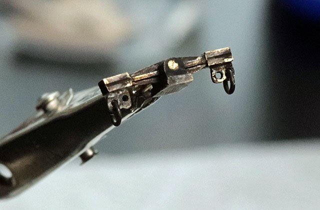
So next will be the Ratchet Quadrants (see the first photo, center left). These will be a bit tricky as the core of the quadrant fits over the ratchet gear teeth and the sides of it ride on the clad disks on either side of the ratchet gear.
- Retired guy and GrandpaPhil
-
2
-
Sorry to hear that. But best to take care of business. Wishing you a speedy and full recovery.
- Overworked724, RichardG, Gahm and 1 other
-
4
-
Sorry to hear about your shoulder. Hope the MRI results show nothing major. Hoisting those beers can be tough.
But I can relate to your feelings of guilt. Spring cleaning and yard work has my progress delayed and my Bluenose is feeling neglected.
Here's wishing you a quick and complete recovery.
-
If anyone is going to purchase a lathe or mill, or if you have recently purchased either of these I highly recommend viewing these videos. Very well done and very informative. While they are based on Sherline products, many of the topics will apply to other brands as well.
-
Nice work! Well worth your time and effort. I've learned, and continue to learn from your build log. Thanks for sharing.
Dave
- popeye the sailor and dragzz
-
2
US Brig Syren 1803 by Overworked724 – Model Shipways – Scale 1:64
in - Kit build logs for subjects built from 1801 - 1850
Posted
As always, your outside the box ideas are ingenious. Thanks for teaching me new tricks!
Wishing you a speedy recovery.