


Toolmaker
-
Posts
193 -
Joined
-
Last visited
Content Type
Profiles
Forums
Gallery
Events
Posts posted by Toolmaker
-
-
Can I ask if any of sets 1&2 have been sent across the Atlantic, and if so can you indicate the cost of the carriage?
Thank you.
- FrankWouts and mtaylor
-
 2
2
-
20 minutes ago, Scottish Guy said:
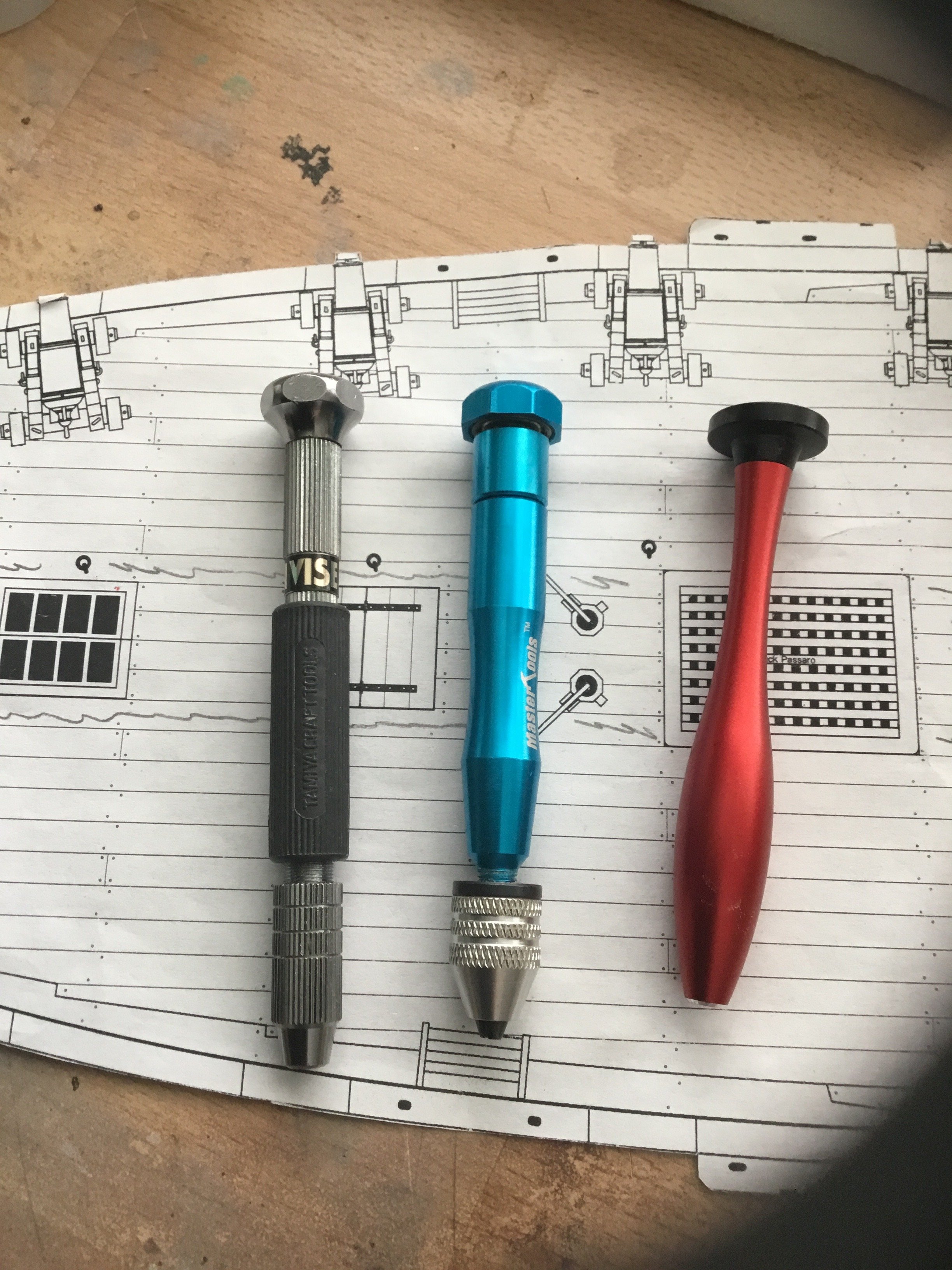
Just wondering, why not using an archimedian mini drill?
For me, that would be a non starter as it lacks the control necessary for much of the work we do on model ships. To use it one handed relies on pressure to create a screwing effect. If you use it 2 handed the workpiece needs to be fixed.
Unless I have the piece fixed in a mill/drill machine then I always use one of these; Designed for one handed use, pressure easily controlled on start and break through. The blue one is my favourite as it has a mini chuck and the bearing system works well.

- thibaultron, Ryland Craze, Canute and 1 other
-
4
-
-
Any decent HSS, high speed steel, bit should hold up, hand drill or otherwise.
Avoid carbide drills unless in a powered milling machine type environment. They are too brittle and prone to break easily when used in/for the purses e you describe.
- mtaylor, Scottish Guy, SiriusVoyager and 1 other
-
4
-
Apologies if this is drifting from your build but I feel it’s worth noting for people looking to build to scale.
I just checked five different 25lb monofilament fishing lines and they were all different. The range was from 0.37mm to 0.52mm. Now 0.15mm which is .006 inch does not seem much, but the variation is actually more than 40%.
Hence me suggesting it is better to know the required diameter rather than the breaking strain.
Very nice start by the way.
-
The mark for the “planking band” takes care of this. Prior to marking any bulkheads you have divided the hull into x amount of planking bands with, usually, narrow tape.
This is marked as the bottom of the planking band.You would now determine how many strakes from your existing planks to the bottom of the band and mark your bulkheads accordingly. I understand you are up to date to this point.
As for marking the filler block, you are still looking to mark the same number of strakes to the bottom of the band. Divide the distance from existing planking yo the bottom of the band by the number of strakes and mark up.
if you wanted to mark all along the filler block you can lay your paper from the mark on bulkhead 1 to the mark on the rabbet and pencil along the paper top but I don’t find that necessary.if I have missed the point of your question then I apologise for misunderstanding it.
Regards
Paul
-
Outstanding high standards Glenn. Every picture an inspiration.
I have high ideals, which of course is not the same as high standards, but I would be beyond joyous if able to match those standards you are displaying.
I am learning my trade on Cheerful but 2025 will be Winchelsea year and along with Chuck’s monographs I shall be having your build log with me as escort.
Thank you
Paul
- Ryland Craze, glbarlow and FrankWouts
-
3
-
29 minutes ago, sfotinos said:
What size drill bit for the treenails using 25lb line?
I think using the breaking strain of the line as a size measurement can be misleading. It would be better to look for a correct diameter rather than the breaking strain. That way you would also know what size drill to use.
Alternatively, measure the line with a vernier and buy the drill to suit.
-
Hey Nic,
Don’t be taken in by that fella above called No Idea, he does have an idea. I would concur with him and go for a Vanguard models kit. In a large part because they are in the UK and if you have any issues they are not far away. My current builds are from USA sourced suppliers but I got a couple of Vanguard kits under my belt first.
I would suggest this kit to test your mettle;
https://vanguardmodels.co.uk/product/fifie-lady-eleanor/The hull shape gives you the best chance of success at this early stage and you can probably buy the kit and all the tools and paints required for under £200 quid. If you go for it and need advice along the way, just shout out.
it was my first dabble at wooden boats and I have lots of photo’s etc
Good luck bud
Paul
- Keith Black, No Idea and mtaylor
-
3
-
I feel like I’m about to be given a most obvious answer, but as I don’t know, I have to ask.
From a ship design point of view, what was the thinking behind the cupola? Why bother?
- FrankWouts and mtaylor
-
2
-
7 hours ago, TBlack said:
Chuck, I see some differences there. In the first picture the top level of window panes is all that visible while in the second photo we get to see two levels of window panes. I am discerning that you haven’t decided which way to go yet.
TomIt’s the angle that the photograph is taken that is misleading you. It’s the same detail in both pictures.
- JeffT, Chuck, Ryland Craze and 5 others
-
8
-
Grainy, if there is such a word. Its no surprise as 3d printing of metal is termed "additive manufacturing". The process is done from grains of metal. It is generally done for very bespoke products and oft times it is more cost effective to machine the parts
This video gives a good overview about the process and why it can be expensive. That said, cost are coming down with basic machines now affordable to hobbyists. I'm certainly no expert but have bought sintered metal products in the past.
-
-
-
On 2/9/2024 at 7:52 PM, wefalck said:
Well, when you tighten a vice the loose jaw often has the tendency to lift or when the guides of the loose jaw have too much play, the jaw can move sideways when tightened. Both the fixed and loose jaw should also close tight and precisely when tightened without a workpiece in it. Finally, the edge of the fixed jaw should be precisely aligned with the body of the vice, so that you can align it easily on the mill table.
The mentioned toolmaker's vices don't have a spindle to tighten the loose jaw, but the jaw is pulled down- and forward by a screw that screws into a sort of 'toggle' underneath the vice. This make the vice also a lot shorter, as there is no spindle sticking out.
Here is a picture of such vice (in my shop-made tilting device:
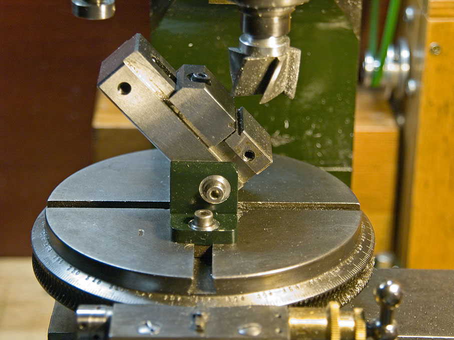
The Sherline vice operates in the way you describe wefalck. This is a link to it for sale in the USA.
https://www.sherline.com/product/3551-milling-vise/#description
-
-
On 2/11/2024 at 12:10 PM, DocRob said:
I´m using a similar model like this one here, Dave. The white tip is a bundle of glass fibers. These glass fiber pencils are very useful, to remove paint on mating surfaces or oxidation from electronic parts. If you use them, you should wear a respirator or at leas a dust mask. There are very fine particles of the fibers in the air, while using it.Cheers Rob
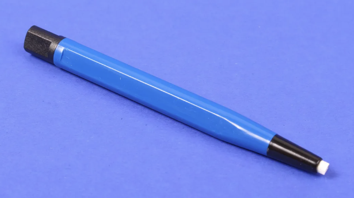
A few seconds with one of these is great preparation prior to soft soldering brass photo etch. Refillable regarding the fibre glass brissles. Your right though Rob, thinking about it I do now wonder about the safe usage, albeit a bit late having used them for years.
-
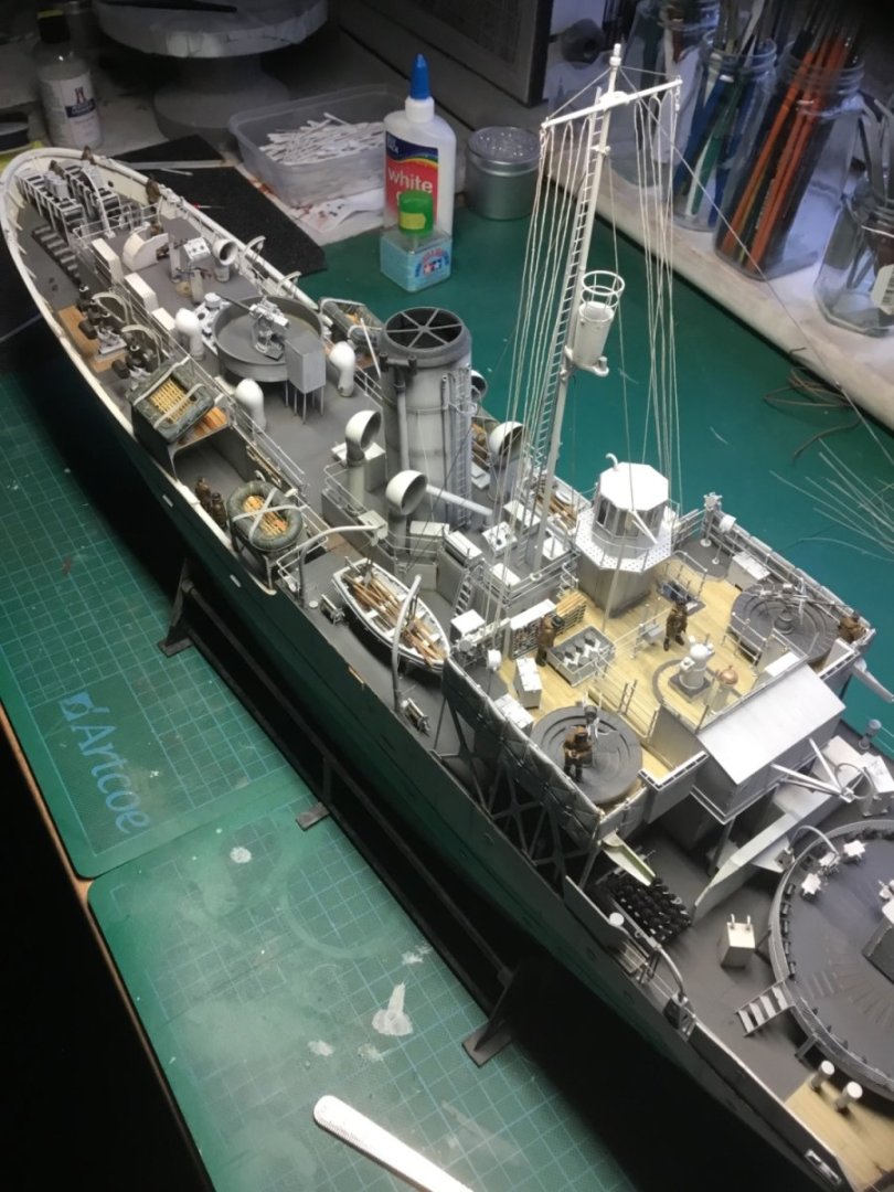
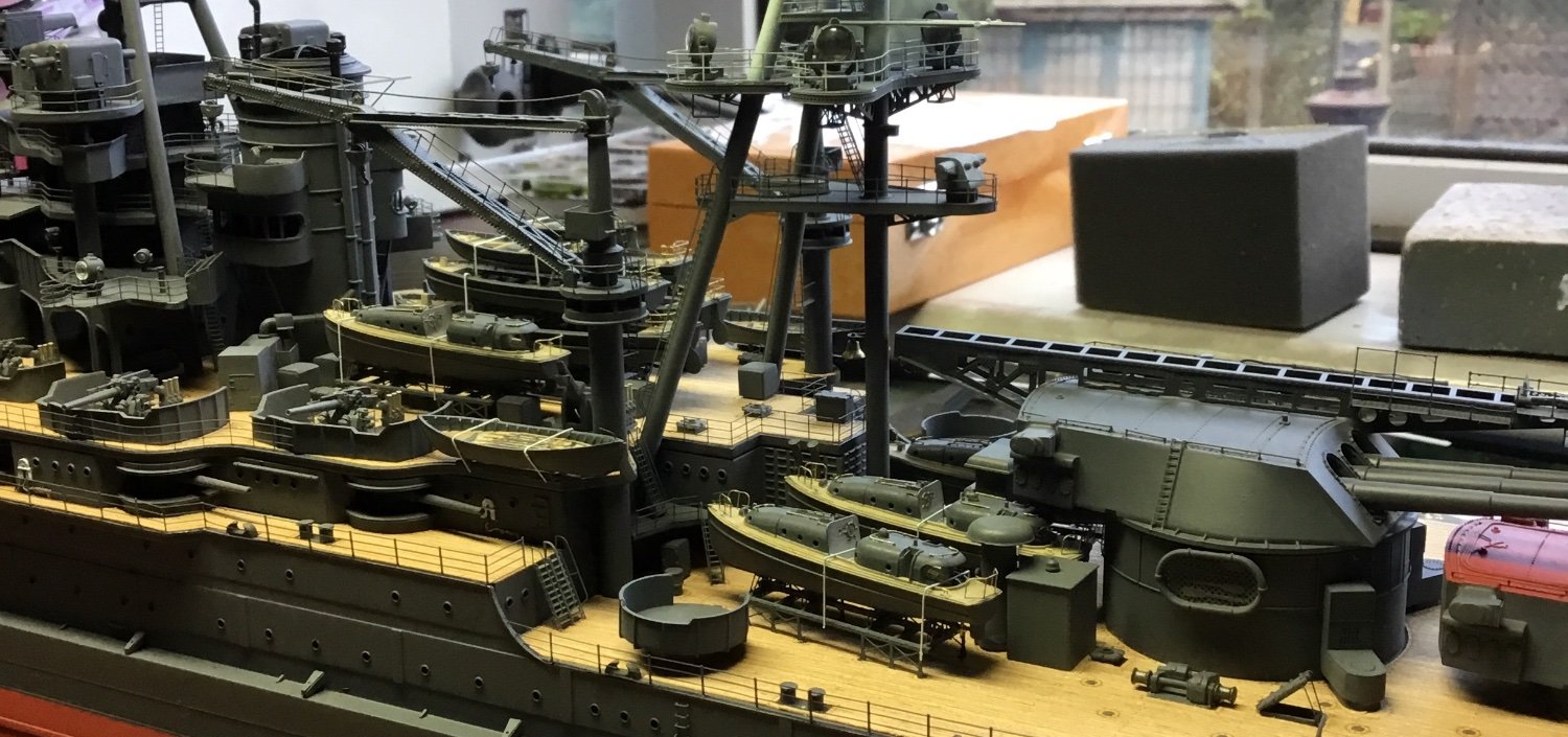
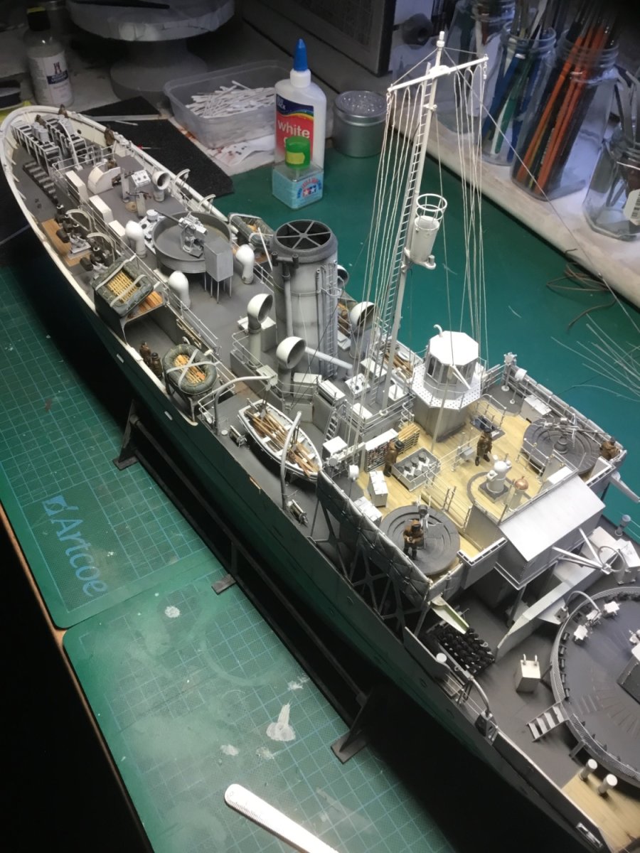
I transitioned from plastic to wooden ship building around 5 years ago. Prior to that I had built 2 plastic ship models, the battleship Arizona and a Flower Class Corvette.
Arizona;

Arizona detail
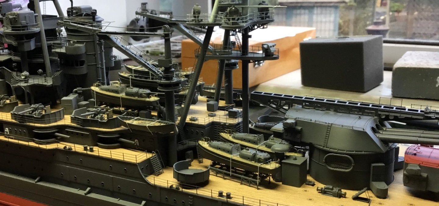
Arizona finished
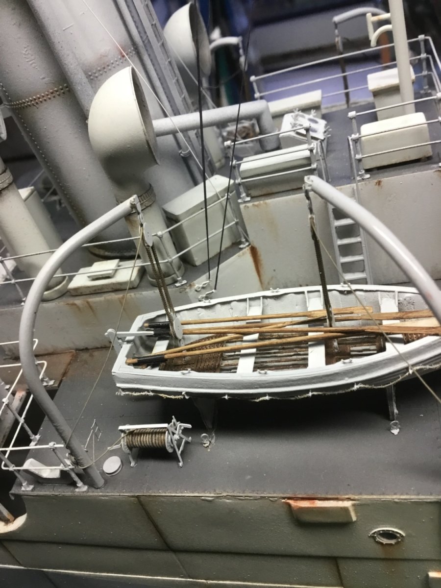
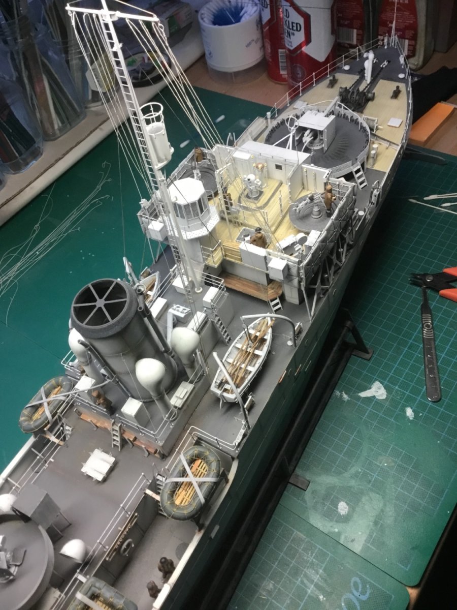
Flower Class Corvette
Flower Class Corvette lifeboat

FCC finished

FCC finished stern
- shipman, mtaylor and GrandpaPhil
-
3
-
I can only offer advice based on industry standard machines. Although I use a miniature Sherline milling machine I do not currently own a model makers lathe.
That said, in the past, at the spindle end I have used 2 jaw, 3 jaw, 4 jaw and collet chucks. Most of the 4 jaw chucks have had independent jaws but self cantering 4 jaw chucks are also common. I have worked with a 4 jaw chuck in a 3 jaw chuck and with a 3 jaw in a 4 jaw.
Regarding soft jaws and their use.
Soft jaws are available for many 3 jaw chucks and certain collets systems have soft collets available. Soft jaws/collets are predominantly used for second operation work. That’s when you have worked on one side of a part but still have work to do on the other side and want to hold it in an accurate manner. Most 1st op work would be done in hard jaws.
So most soft jaws become stepped. You can step the inside of the jaws or the outside. The jaws have to be locked firm when you machine them. For utmost accuracy If you are stepping the inside of the jaws (to hold on the outside of your part) then you should clamp a piece of round bar in the chuck and bore the jaws to the same diameter you want to hold your part or very slightly larger. Conversely if you want to hold on the outside of the soft jaws you should hold a ring on the outside of the soft jaws. This method is to give better likely concentricity accuracy but in practice hobby machinists will likely clamp the jaws the same way as before, on a piece of round bar.
Full soft jaws, sometimes called pie jaws, are useful when holding thin walled parts. These parts might likely distort if you held them in traditional 3 jaws, soft or otherwise.
One instance when you might wish to bore soft jaws through is when you want to avoid damage from hard jaws, whilst wanting good concentricity from one end to the other of a shaft.
You can also have soft jaws for your milling vice allowing you to hold specific shapes and without needing parallels.
To be honest, most of this is referencing model engineering rather than wooden ship building but take it as a snapshot of soft jaw usage. I’m sure lots of usage videos are available on the internet.
Most important message is work safely. 50 years ago I was told by a foreman “you can walk on a wooden leg, but you will never see out of a glass eye”.
-
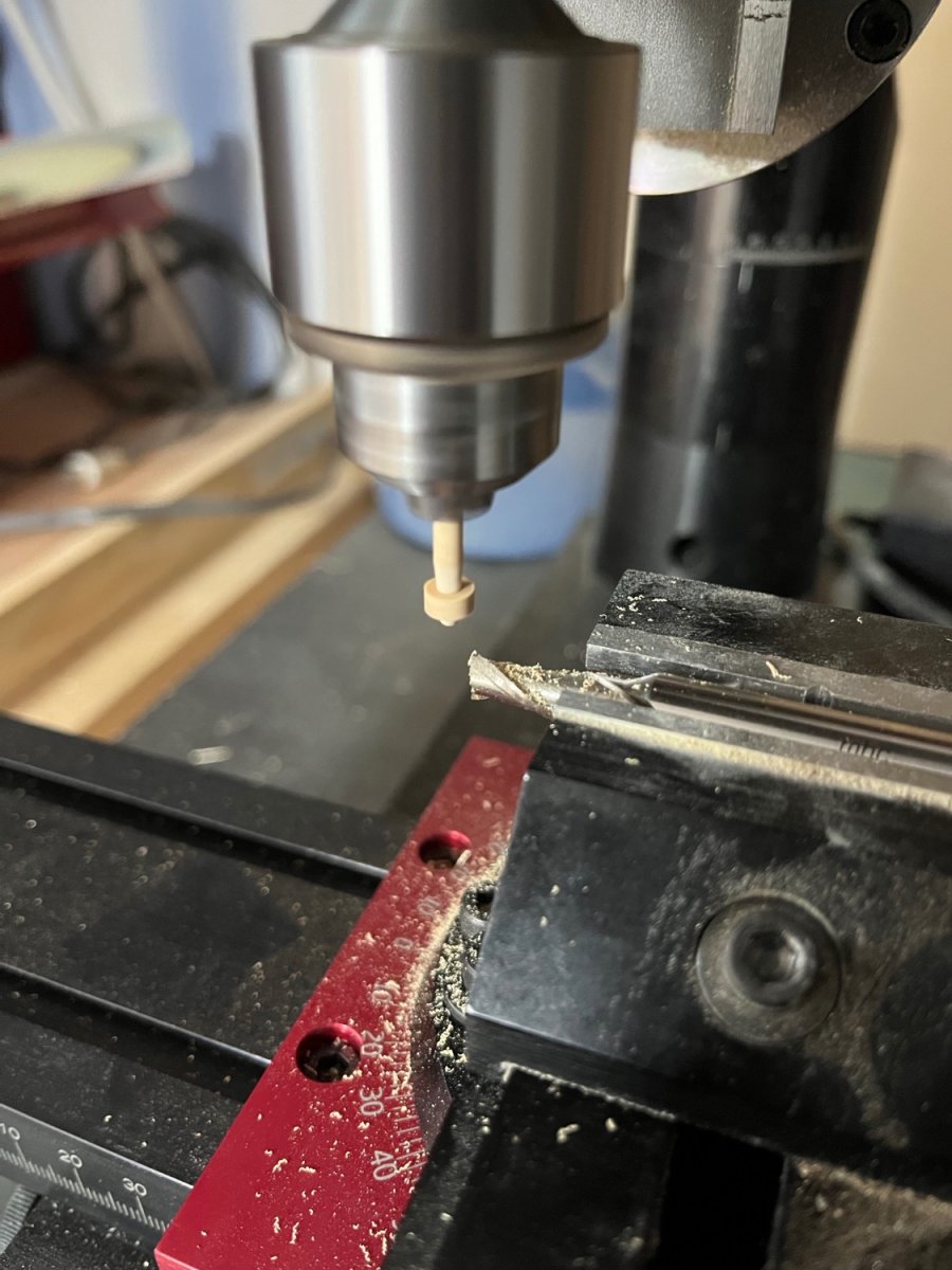
It’s only slight drift as we are still on milling cutters. You are showing your experience now, using milling cutters as stationary tools, as in your boring bar.
When turning small aluminium parts (usually optical instrument housings) we would often plunge with a slot mill and then finish bore with the same tool. No tool change required. Years later they developed specific tools for this.Here is another instance using a stationary milling cutter. I am trimming Syren cannon wheels to remove the char and to true from the centre hole. The parts are just pushed onto a tapered wooden mandrel and fed down past the cutter.

-
37 minutes ago, wefalck said:
Unlike toolmaker it seems, I am a mere self-taught amateur ...
Maybe, but it’s a long time past that I did much serious practical work, and there is not much “mere” about either your advice or your machining output. I always enjoy reading your posts.
-
Ron,
Great explanation there from wefalck. I’m always grateful that he can be bothered to do the hard work of explaining things fully.
Mark (No Idea) would also advocate 2 flute cutters for easier chip removal and he would likely suggest this site for cutters;
https://cnc-plus.de/en/End-Mills-266/
For you, being in the US, you should just look for a stateside supplier of quality tools. I tend to use good quality metal cutting tools and having a Sherline miniature mill I am able to run the cutters at multiple 000’s of rpm. If the machine is rigid and the cutters are running true, you can’t go too quick with wood. Guhring is the make I use generally but I have also bought generic cutters from Amazon.
The beauty of using sharp tools on wood, whether machines or hand chisels, is that you are not creating dust and you can get a better finish against using sanding methods.
btw, a standard end mill is suitable for all those examples you have shown.
-
Terminology has to be learnt and even then can remain confusing when we are writing explanations from different countries.
Not all milling cutters can be used to “plunge” cut. In the UK the different types of cutters regarding this issue were known as “end mills” and “slot mills”
What is the differences between a Slot Drill and an End Mill? A slot drill is a mixture of a drill and an end mill meaning it can plunge in like a drill then slot across like an end mill. Conversely, an end mill will primarily cut laterally and horizontally.
If you want your cutters to be able to “plunge cut” make sure you buy the right sort.
Another relevant term is climb/conventional milling. Whether your cutters have right or left hand flutes it will be the direction of travel that dictates whether you are climb milling or conventional milling. This terminology is also known as “up” milling and “down” milling depending where you learn your trade.
There is plenty of internet explanation for the different methods. If your milling for a living it’s worth knowing but for hobby milling taking very small cuts on wood it is really not important.
Member No Idea has discussed milling cutters on his build log and I think his advice is as good as you will ever need.
Good luck with your milling
cheers
Paul
-
22 hours ago, wefalck said:
An old-time machinists' approach is to use two fixed centres, in the spindle and in the tailstock, and hold a razor-blade between them. If the centres are aligned correctly, the blade should be perfectly vertical and at 90° to the bed.
Brilliant!
I’ve spent 40 plus years hanging out around machine tools and I had never seen, heard or considered that. I can clearly see it in my head though. It’s the sort of initial alignment check you could do during a rebuild.
One approach to working more accurately than the handwheel graduations is to put a dial test indicator (dti) against the slide and take your movement from those. This method is more easily done on larger machines with metal bedways and less size constraints. The dti is usuall on a magnetic block.
A good digital readout is even better, thus removing the pesky backlash error.
Oh the wish list is endless.


Bending hard brass.
in Metal Work, Soldering and Metal Fittings
Posted
It might be worthwhile getting a larger piece of brass and machine the part you require. Saw and files or power tools if you have them. I think this method would be more easily controlled and offer you a better chance of success. Brass is quite soft and files to shape quickly.