HOLIDAY DONATION DRIVE - SUPPORT MSW - DO YOUR PART TO KEEP THIS GREAT FORUM GOING! (Only 44 donations so far out of 49,000 members - C'mon guys!)
×


BANYAN
-
Posts
5,938 -
Joined
-
Last visited
Content Type
Profiles
Forums
Gallery
Events
Everything posted by BANYAN
-
 Stunning Denis; those standoff shots in particular make the model looks so life-like (colour and atmosphere). Nice work mate, that detail really pops; especially like the little things like the brass handrails etc. cheers Pat
 -
Nice work again on those 25s Greg; that ship sure had some close range fire power. 28 of this miniscule things; not just cross-eyed but a bit of a headache also I'd guess? cheers Pat
-
Poochiie, have a look in the sites database of articles for a good article on this subject and many others that can assist you. http://modelshipworldforum.com/ship-model-materials-and-tools.php cheers Pat
-
Nice work Dave and thanks for the pointer to Tom's work, but to find it please? cheers Pat
- 742 replies
-
- 5
-

-
- constitution
- frigate
- (and 1 more)
-
Very nice job on the 20mm cannon / guns Greg, even if only a 6 of them, that is very well detailed and came up a treat. cheers Pat
-
Your promised a nice addition, and probably a surprise or two left, and you haven't disappointed Looking really good mate. cheers Pat
-
Cruizer-class Brig-Sloops of the Royal Navy
BANYAN replied to molasses's topic in Nautical/Naval History
Some great reading here, thanks BW and all contributors. cheers Pat -
Nice progress Ulises, those pin racks look good (and solid ) cheers Pat
- 786 replies
-
- 3
-
-
- Royal Louis
- Finished
- (and 1 more)
-
That is a great bit of detailing Greg, looks really good and I like the idea you have for hanging a float plane from it. cheers Pat
-
Found your log this morning cog; sorry to be late to the show. Looks like another very highly detailed model in the making here. Those turret enhancements look great Make room in the front row for me too please cheers Pat
-
I agree with Gunther; whatever you thinks looks best in situ. cheers Pat
- 310 replies
-
- 3
-
-
- cheerful
- Syren Ship Model Company
- (and 1 more)
-
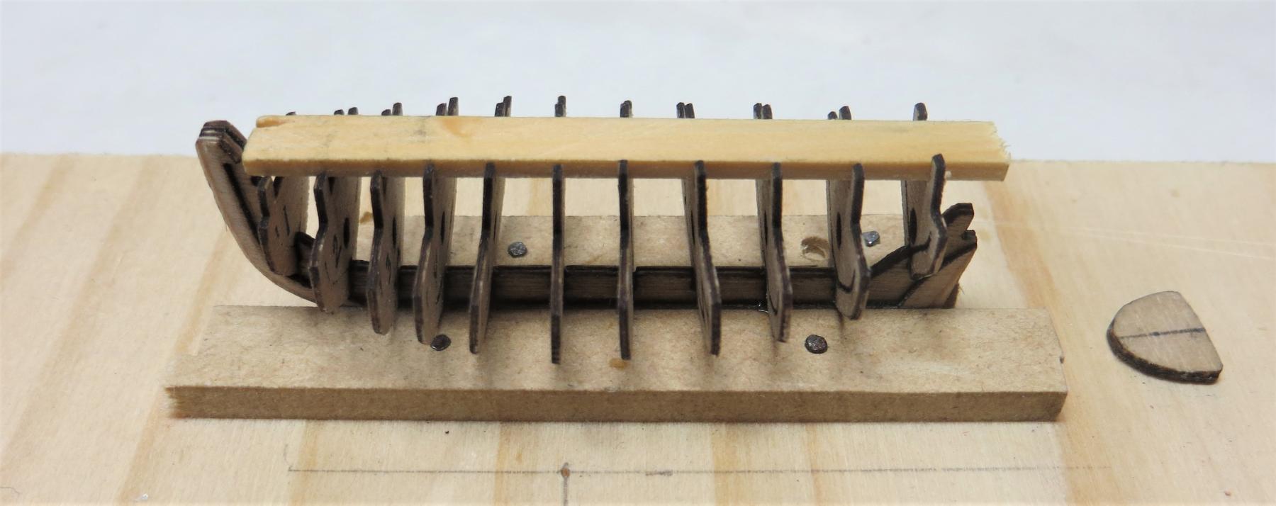
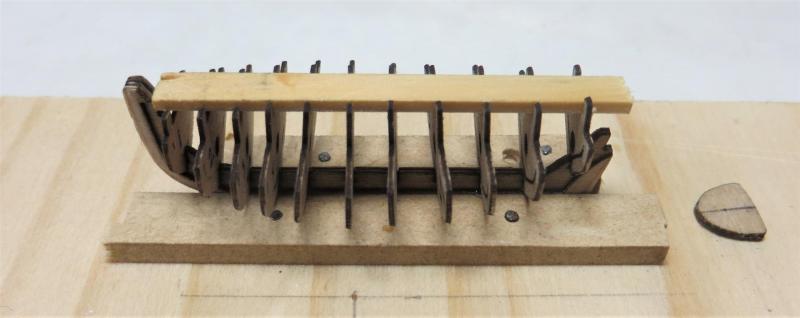
A small update, the frames/temp bulkheads have now been fitted in a basic jig. The longitudinal temp stiffener has yet to be glued and will be done after I straighten a couple of the frames. The eagle eyed will note a couple of frames not quite aligned; some of this is due to camera angle. Gluing in the longitudinal stiffener will help keep them in place vertically, but first I need to fix/redo at least one of the frames. This system works quite well and was well laid out by Dave when he did the artwork as I did not need to do much filing for fit at all. The holes in the temp bulkhead (which will be broken away later) were for a toothpick to pass through to assist with alignment, but at this scale almost impossible to utilise and too fiddly. Sorry all, I forgot the ruler again but this is only about 80mm long (just over 3") overall. cheers Pat
- 517 replies
-
- 9
-
-
- Endeavour
- Artesania Latina
- (and 1 more)
-
Persistence pays off Denis, those nets will look great on the model..... and a couple of spares to boot cheers Pat
-
Hi and a very Happy New Year Rusty, nice progress. The links work but on PC at least, the thumbnails are not showing? cheers Pat
- 310 replies
-
- 2
-
-
- cheerful
- Syren Ship Model Company
- (and 1 more)
-
Very nice job on those gudgeons Jason; that rudder looks a lot better. That transom is going to look very good when finished and well worth the effort you are putting into it. cheers Pat
-
Wow!!!!!! that is going to be one very nicely detailed model if this is any indication Wefalck. cheers Pat
-
Another beautiful model John; she looks great. Particularly nice to see another model that is not mainstream and preserves the history of these vessels. cheers Pat
- 745 replies
-
- 4
-
-
- francis pritt
- mission ship
- (and 1 more)
-
Much easier Greg Denis, the idea/concept was developed by Chuck who does this with his small boat series; Dave has just adapted it a little to serve his needs (and the lucky soul has access to a laser cutter) Thanks for all who looked in and gave a 'like" cheers Pat
- 517 replies
-
- 4
-
-
- Endeavour
- Artesania Latina
- (and 1 more)
-
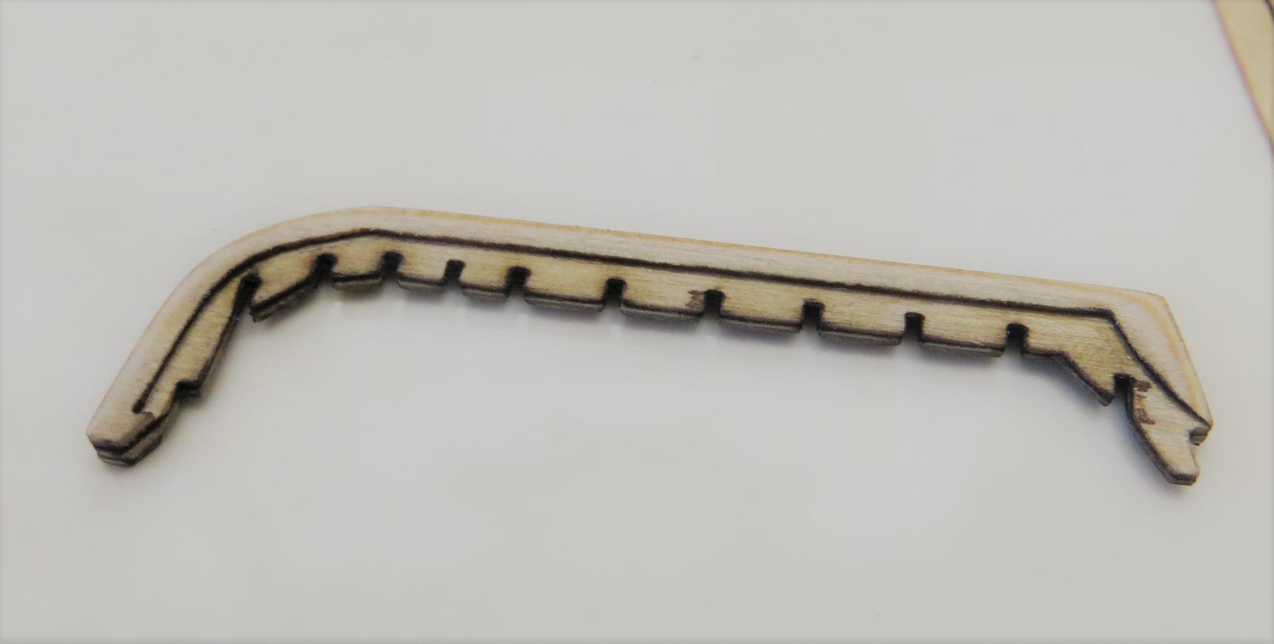
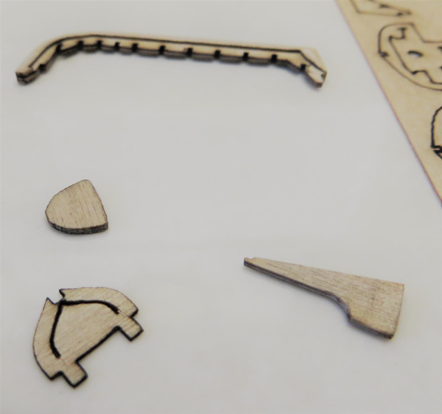
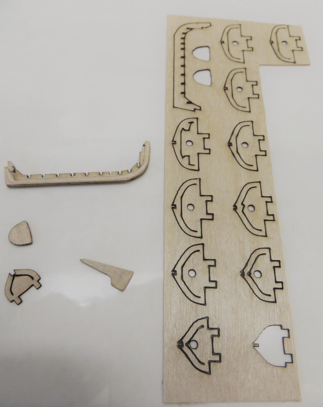
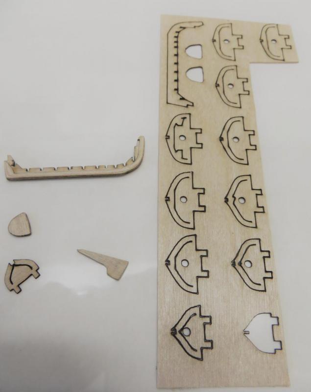
Hi again folks; hope you all had a happy and safe festive season. I have made a start on the two remaining boats to complete my build; the yawl and the skiff. I am doing these part-time between the yard chores and HMCSS Victoria. First, I would like to thanks DaveRow who has kindly designed the laser templates and cut the boat templates for his build but provided me with a spare set; many thanks Dave. These are great, and make assembly a lot easier. The template is 0.6mm thick so the keel is a lamination of 4 layers which creates a natural rabbet. The rudder and transom piece are 2 x lamination but the remainder of the pieces will be single. I don't think I would have achieved this level of detail without the template. i will stage a ruler in my next set of shots to give a better idea of scale. cheers Pat


- 517 replies
-
- 8
-
-
- Endeavour
- Artesania Latina
- (and 1 more)
-
Great to see you back Remco and to see that lovely model of yours again. cheers Pat
- 1,215 replies
-
- 3
-
-
- sloop
- kingfisher
- (and 1 more)
-
Nice to see you back at this model Wefalck; look forward to seeing her evolve. cheers Pat