BANYAN
-
Posts
5,951 -
Joined
-
Last visited
Content Type
Profiles
Forums
Gallery
Events
Everything posted by BANYAN
-
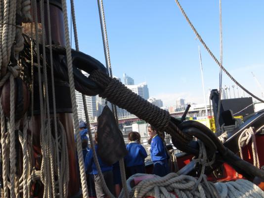
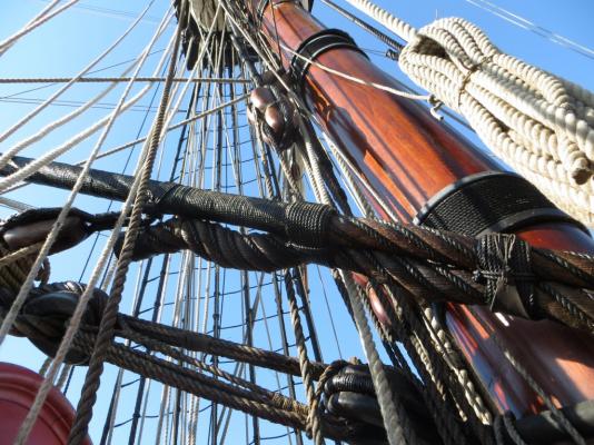
 The following photos show the various aspects of the parts designed by Bogey and printed in 3D (Frosted Extreme Detail - FXD) by Shapeways. This is my first resin 3D printed kit so I do not have much to compare with. That said it appears a sound kit; I certainly cannt complain about detail as Bogey has included everything we could find to represent her appearance in 1975/76. This detail shows up very well even at this scale (1:350). I will provide a more detailed report of all of the bits and pieces as I get to grips with what is / is not provided and where greater detail will be needed. These are the kit bits and pieces provided: There are still a few bits to come (mainly deck fittings), some PE and the decals. I look forward to making a start as the research has been quite enlightening - trying to remember what all the equipment and their locations and arrangements. I must also thanks Jim Lad (John) for the many trips to Vampire photographing all the details for me. cheers Pat
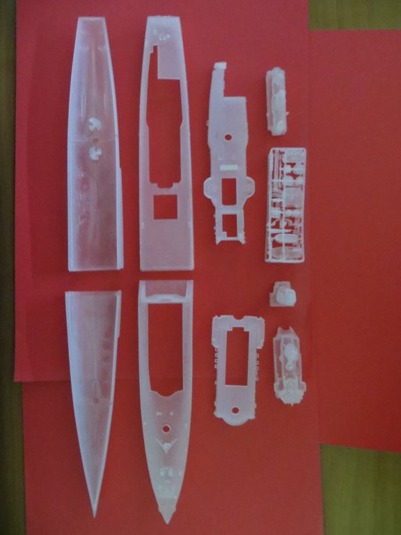
-
Introduction The following overview of HMAS Vampire is adapted from the description provided in Wikipedia. Further details can be found at: http://www.navy.gov.au/hmas-vampire-ii and https://anmm.wordpress.com/tag/hmas-vampire/ The Royal Australian Navy initially ordered four Daring class destroyers, which were to be named after the ships of the "Scrap Iron Flotilla" of World War II. The ships were modified during construction: most changes were made to improve habitability, including the installation of air-conditioning. Vampire and her sister ships were the first all-welded ships to be constructed in Australia. The Darings had a standard displacement of 2,800 tons, which increased to 3,600 tons at full load. Vampire was 390 feet (120 m) long, with a beam of 43 feet (13 m), and a draught of 12 feet 9 inches (3.89 m) at mean, and 14 feet 6 inches (4.42 m) at full or deep load. Her propulsion system consisted of two Foster Wheeler boilers, feeding two English Electric geared turbines, which provided 54,000 horsepower (40,000 kW) to two propeller shafts. Vampire could sail at over 30 knots (56 km/h; 35 mph), and had a range of 3,700 nautical miles (6,900 km; 4,300 mi) at 20 knots (37 km/h; 23 mph). Her standard ship's company consisted of 20 officers and 300 sailors. Vampire was laid down at Cockatoo Island Dockyard in Sydney, New South Wales on 1 July 1952. The destroyer was launched on 27 October 1956 by the wife of the Governor-General, Sir William Slim. She was completed on 22 June 1959, and commissioned into the RAN in Sydney a day later. In June 1970, Vampire was handed over to Williamstown Naval Dockyard for a $US10 million modernisation. Vampire re-entered active service on 4 March 1972. On 25 June 1986, Vampire left active service. She was decommissioned on 13 August 1986, having spent 27 years in service, and travelled 808,026 nautical miles (1,496,464 km). She was later presented to the Australian National Maritime Museum for preservation as a museum ship. I will be depicting her as she was when I served in her in 1973 through to mid-1976 when she was COMAUSDESRON 2 (Commander Australian Destroyer Squadron 2). Her livery will reflect the “pretty work” detail she had when were deployed to the SE Asia station and her visit to the US Bicentennial celebrations. She will therefore be sporting nice white bollards, fairleads and other tiddly bits . At that time, post-refit, her main armament comprised six 4.5-inch (110 mm) Mark V guns mounted in three Mark 6 twin turrets, two forward and one aft. Her anti-aircraft outfit consisted of six 40 mm Bofors; two single mountings on the forward superstructure, and two twin mountings on the aft superstructure. Four 0.5-inch (13 mm) Browning machine guns were carried for point defence. For anti-submarine warfare, a Limbo anti-submarine mortar was carried on the aft deck, offset to port. Vampire was fitted with a Type 170 attack sonar, a Type 174 search sonar, and a Type 185 submarine detection sonar. The fire control directors were two WM22 units. The long range air warning radar was an LW-02, and an 8GR-301A surface search and navigation radar was installed. cheers Pat
-
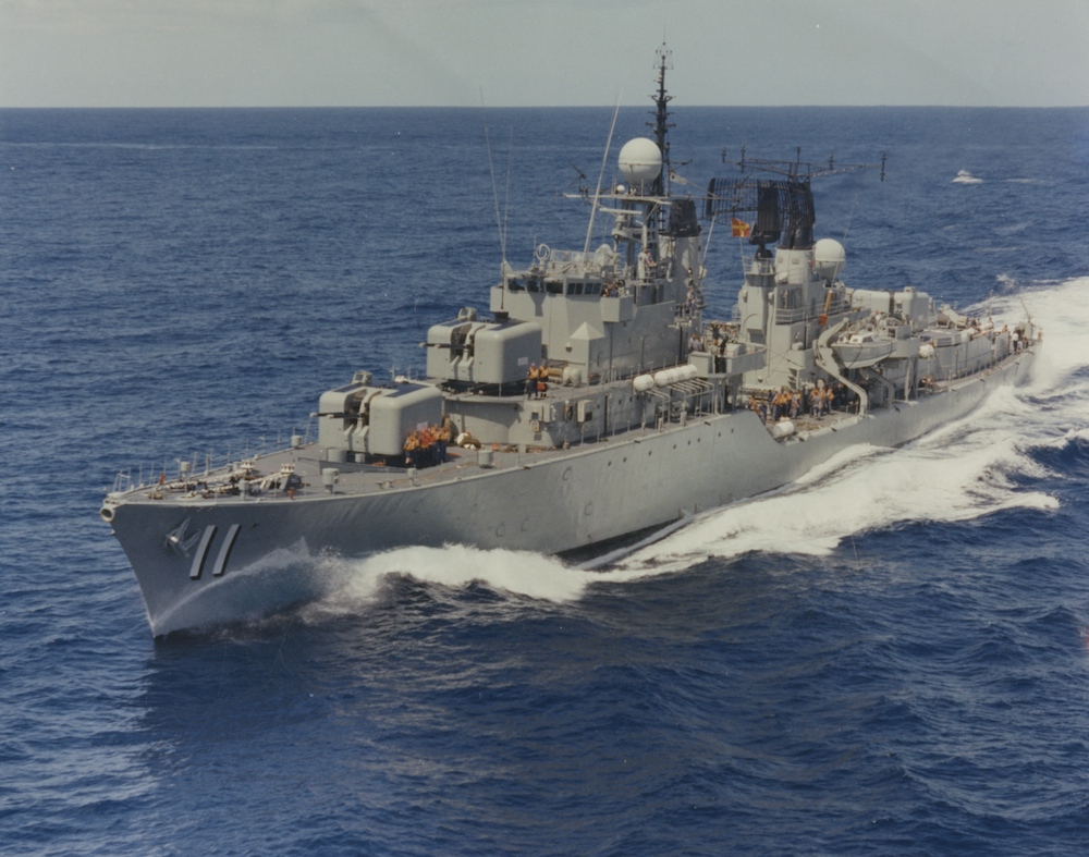
Hi folks, My next project will be the HMAS Vampire based on a 1:350 #D printed model from Bogeys Bits (via Shapeways). I served a very enjoyable 2.5 years in this ship and it will be a joy building this model of her as it will rekindle many good memories. This photo is from the official RAN website. This log is being started now but no serious work will begin before mid-2016 while I research, acquire detail parts etc and get to grips with working with this material. This is my first non-wood build so I will be learning a lot as I go. In the meantime I will have to devote some serious time to my long-suffering Endeavour (if I don’t, the Admiral will have some stern words ). Introduction Hull Main deck B Deck (forward lower superstructure) X Deck (after lower superstructure) Bridge and GDP (Gun Direction Platform) Main Mast Funnel Radar Superstructure Boats and Davits Main Armament Secondary Armament Cheers Pat

-
Nice looking rope Paul. cheers Pat
-
Chuck, try a jig made from scrap square. Drill out / bore the square first to the size of your dowel (if you have a mate with a lathe get them to do it - much more accurate), then cut it in half. This makes the placement and holding of the round dowels much easier. You can have several sizes all ready to go. Select the appropriate size, hold it vertically/horizontally in a vice and centre it (again easier using the square). A couple of tips; cut dowels to a minimum workable length - the longer the piece the harder to keep it aligned for the vertical bore. For horizontal drilling, use the same jig - again much easier to find the centre line. For regular (repeatable) positioning of these holes use a stop for the round dowel once you have measured up for the first drill. As long as you have taken the time to make the square (jig) centred the rest is a production line effort. cheers Pat
-
Really nice rigging Danny; she is coming along like a true masterpiece of work.
-
Remco, I think they may need to find a new definition for 'perfection" - absolutely stunning joinery. cheers Pat
- 1,215 replies
-
- 3
-

-
- sloop
- kingfisher
- (and 1 more)
-
She is looking superb Rusty and build into a very fine model. Chuck's 'bits and bobs' look excellent quality; thanks for the feedback on those. cheers Pat
-
Now that she has almost all of here 'skin' she is showing those lovely lines to perfection John. Looking great! I might add that around trying to advance his model with his time at the ANM, John has been kind enough to tramp all over the ex HMAS Vampire taking lots of detail shots for me, for an upcoming build - ta mate! cheers Pat
- 745 replies
-
- 1
-
-
- francis pritt
- mission ship
- (and 1 more)
-
HMB Endeavour by mikec - Eaglemoss
BANYAN replied to mikec's topic in - Kit build logs for subjects built from 1751 - 1800
That's a great tip, and nice looking rigging mate - your Endeavour is coming along really nicely. edit: my only concern would be longevity as elastic tends to break down after awhile - have you any feedback from the 'seamstress' in your life cheers Pat -
Errors or not Mark, that's still a nice build and informative log. Best wishes for s a safe and happy festive season. cheers Pat
-
That is looking great Sharpie; maybe santa's helpers can assist with the planking now their chores are mainly over Look forward to your next progress report. Happy Christmas Pat
-
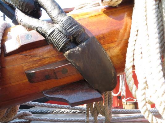
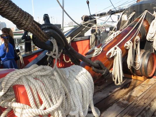
Hi Mike, Karl's book can be confusing until you work out what he is doing with the drawings I still need to double check myself. The drawings on page 101 are the standing rigging associated with the mizzen, main and fore masts as generic depictions for the stay details (Figure H3/4) - it is not meant to represent the mainmast or the foremast, but both and then further detail is broken our as required for the mizzen mast on the page (diagrams below H3/4) and other pages. You need to reference back to page 95 with items 36, 37, 38 and 39 of interest, as are 57, 58 and 59. Lets deal with the main mast first with reference to 57, 58 and 59. The mizzen stay is terminated with a heart and lashing to a sling with a heart collar around the base portion of the main mast. The first detail drawing (lower left) on page 101 shows the rigging termination for the page 95 item 58 (Mizzen Staysail Stay) at callouts 11 (corresponding to 58), 12 and 13 which terminated at an eyebolt on the deck at the foot of the mast. The second detail drawing (under H3/4 on page 101) shows the terminations/rigging for the mizzen topmast stay (no preventers). Now let's deal with the Mainmast stays and preventers for which we need to treat figure H3/4 as the foremast. Then the main stay and main preventer terminate with hearts and collars at the foremast and near the jib respectively. The preventer rigging is another story which I can deal with when you get there. The main topmast stay (3) and stay preventer (5) are rigged as shown in this figure (H3/4) with both terminating with tackles at the deck as described at (7). the main topgallant stay is terminated as a hitch to the main topmast stay collar as shown at (4). The foremast stays and preventers are shown on page 95, items 15 through 19. Now back to the main mast stay preventer, which leads past the foremast and all indications are that it terminates as a lashing (via hearts with a lanyard) to an eyebolt in the peak of the ship to stbd of the boom. If you project the line of this stay preventer on the drawing on page 95, this supports this. However, to me that would put the rigging of this preventer in an awkward place for some anchor/cable working evolutions. The folks on the Endeavour Replica must have thought the same and they use a unique lashing arrangement that employs a sling around the base of the jib boom and a 'scotchman' (anti-chafing device) on the stbd side of the foremast where the preventer will rub. Jim Lad was kind enough to get some pictures of this for me which I post below. Up to you which method you choose. Page 114 is running rigging in my version of the book? Could you please identify exactly where the confusion with the rigging block is as I can't find it - sorry I hope this helps to clarify a bit? cheers Pat
- 517 replies
-
- 5
-
-
- Endeavour
- Artesania Latina
- (and 1 more)
-
You can never have too many clamps in a workshop, from C, F, G, parallel, machinist and pipe clamps to hair clips (DanVad tip) and rubber bands and surgical tubing, you never seem to have enough of 'that right' clasp for the job at hand. Yep I have all the previously mentioned including those little (toy) wooden pegs and a small-bucket of those plastic clamps from the local hardware store. cheers Pat
-
A big milestone indeed - rack the champers and have several with Christmas dinner mate. cheers Pat
-
HMB Endeavour by mikec - Eaglemoss
BANYAN replied to mikec's topic in - Kit build logs for subjects built from 1751 - 1800
Mike, the best thing would be to download the rigging size calculator developed by Jim Lad. You simply put in the required info and it pumps out all the info you need. I simply rounded most of these to the nearest full mm and then selected several sizes using the closest fit for the in-betweeners. This is the one by Jim Lad http://modelshipworldforum.com/ship-model-rigging-and-sails.php - Just go to the first worksheet (first tab at bottom) and follow-the instruction. Hope that helps cheers Pat -
Hi again Mike. I am back at home and have had a chance to check the paperwork and find I need to advise a small change. While both he main and mizzen are raked back; the main is only 3 degrees (87 to the deck), the mizzen as advised. The foremast is perpendicular to the deck/waterline. cheers Pat
-
Hi Mike, yep those two are. at about 7 degrees aft rake (83 degrees from the deck) according to the kit instructions (AL) which I think were about right but I would need to check the other reference material I have. cheers Pat
-
That's very nice, neat and well finished rigging Danny. No fuzz at all that I can see (even at macro level)). cheers Pat
-
That looks great Sharpie; and a working model to boot (well sort of ) When remaking/replacing the winch dowel (axel/spindle) have you tried a much harder grade of wood and ensuring the grain is in the transverse direction ( I expect you have but just in case) - a really hard wood while more difficult t shape may provide the strength you need without oversizing too much? cheers Pat
-
She's coming along nicely Mark; you'll have the quarter galleries on before you know it cheers Pat
-
I am Considering a Plastic Build and Need Advice
BANYAN replied to BANYAN's topic in Plastic model kits
Thanks for the pointer Nigel; I was aware of this site and that White Ensign has shut its doors but I will have to have a better search of LionRoar etc. Of note, it is not the latest Darings (Type 45) I am after but rather the post-WWII Darings (updates of the old Battle Class). I don't know where I am going to find these bits I note L'Arnel have some stuff but their descriptions are poor so I don't know exactly what they offer and they don't have PayPal facilities. Chris; for a while there I thought I was the proverbial jinx - every lugger I served in payed off (After Vampire I posted to Duchess, then Yarra, then the Melbourne ...) I finally made it to the Teflon navy with Darwin cheers Pat -
I am Considering a Plastic Build and Need Advice
BANYAN replied to BANYAN's topic in Plastic model kits
Hello again all - the lure of plastic (well resin anyway) finally got to me and I have plunged into the deep end. I have purchased the OzMods 1:350 resin kit of HMAS Vampire II (Daring Class destroyer) in which I served for several years (1973-76). At least she has been preserved as a Museum piece by the Australian Heritage Fleet (Sydney). For a picture please see: http://www.navy.gov.au/hmas-vampire-ii I wish to detail-up this kit and I am looking for some pointers to aftermarket detailing such as photoetch and gun barrel/turret products for the ship. She was fitted with three dual gun 4.5" QF turrets (QF 4.5-inch Mk I – V), 2 x single 40mm bofors and 2 x twin 40mm bofors. When she fired a broadside, you knew all about it I am building her as fitted post-moderisation but before conversion to the training role so she will also have the triple barrel 'Limbo" ASW mortars aft. I am aiming to paint her as she was during the period I served in her when a lot of her time was spent showing the flag in SE Asia - so a lot of her fiddly-work was painted to make her look the "ants pants" - detail such as bollards and fairleads were painted white (grey again when we returned to Australia. Some of the detail I am looking for are the various davits, boat falls, antennae (DF etc), ship's lighting etc. Many of these will be the same as fitted to contemporary Britsh designed ships of the era (1950-1970). If anyone could please identify potential sources for these aftermarket products / Detail-up kits I would greatly appreciate it. regards Pat -
A true work of art mate; and especially more amazing noting the scale you were working at. cheers Pat
-
That's a 'corker' of an idea (sorry have been resisting for some time - must be silly Monday Good idea to tuck away in the 'useful' ideas catalog - thanks Pat