BANYAN
-
Posts
5,954 -
Joined
-
Last visited
Content Type
Profiles
Forums
Gallery
Events
Everything posted by BANYAN
-
 Love the detail you are adding Glen, quite the diorama! cheers Pat
- 194 replies
-
- 3
-

-

-
- Bottle
- Treasure Fleet
- (and 3 more)
-
Stunning detail and very well executed Greg; some great eye candy. cheers Pat
- 203 replies
-
- 7
-
-
-
- Roma
- Micromaster
- (and 4 more)
-
HMCSS Victoria 1855 by BANYAN - 1:72
BANYAN replied to BANYAN's topic in - Build logs for subjects built 1851 - 1900
Thanks for the feedback and comments Eberhard and Mark, and for all the 'likes'. Eberhard, yep, hopefully I will be able to make all of it, but may resort to suitable thread if I have no luck with the smaller stuff. I'll have a close look at that fly tying thread, but my concern here would be a colour match with the thread I have found for the silver/grey to simulate wire - this latter is a Gutterman cotton (long staple). cheers Pat- 1,013 replies
-
- 3
-
-
- gun dispatch vessel
- victoria
- (and 2 more)
-
Ditto Looking really good Rob, the furled sails really add to the look, and I am seriously considering this for the Victoria. cheers Pat
- 3,560 replies
-
- 2
-
-
- clipper
- hull model
- (and 2 more)
-
HMCSS Victoria 1855 by BANYAN - 1:72
BANYAN replied to BANYAN's topic in - Build logs for subjects built 1851 - 1900
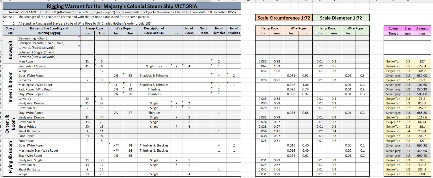
Hi folks, this post is one for those interested in just how much scale rope would be required to fully rig a vessel in the mid-19th century (steam/sail). HMCSS Victoria was rigged as a three masted Barque with a full outfit of fore-and-aft sails). After transcribing a copy of her Rigging Warrant into an Excel Spreadsheet, I used some background formulas and pivot tables to calculate the various sizes of thread I would need and was very surprised with the result. This may not surprise the more experienced modellers, but needing over 71 metres of running rigging scale rope was somewhat enlightening for me (and that doesn't include some of the extraneous stuff like lacings, some rigging tackles, gun tackles, boat rigging (5 x boats) etc. Please note that I am using silver grey thread to simulate the wirerope rigging - using wire would simply destroy the rigging fittings at this scale. I am posting an example of one of the worksheets (that for the Bowsprit and combined Jib Boom) the spreadsheet. The scary bit - how do I make 0.1mm rope I think I will just have to find some suitable sized thread, or simply round these out a bit and use say only 3 or 4 sizes but stick to the principle of lighter ropes to the upper rigging etc. cheers Pat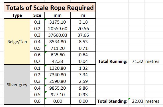
- 1,013 replies
-
- 10
-
-

-
- gun dispatch vessel
- victoria
- (and 2 more)
-
Keith, can you get heat shrink of this small a diameter (and right colour)? Might make life a little easier for simulating the wire coverings. I love that photo of your helper (dockyard assistant) - looks like she is well on her way to lofting plans Hopefully I can encourage both my granddaughters to help cheers Pat
-
HMCSS Victoria 1855 by BANYAN - 1:72
BANYAN replied to BANYAN's topic in - Build logs for subjects built 1851 - 1900
Thanks everyone for the comments and encouragement; and welcome aboard French Mr Bean - appreciate your kind comment. Good ideas Eberhard and Druxey, I will experiment with those techniques but I must admit I have never had much luck with concentricity when boring out cheers Pat- 1,013 replies
-
- 1
-
-
- gun dispatch vessel
- victoria
- (and 2 more)
-
HMCSS Victoria 1855 by BANYAN - 1:72
BANYAN replied to BANYAN's topic in - Build logs for subjects built 1851 - 1900
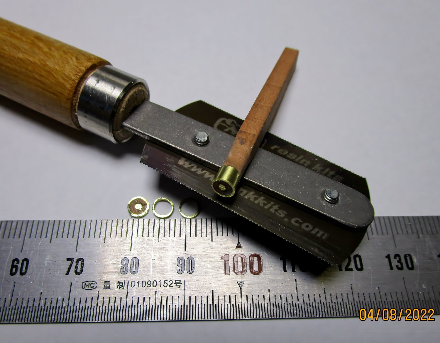
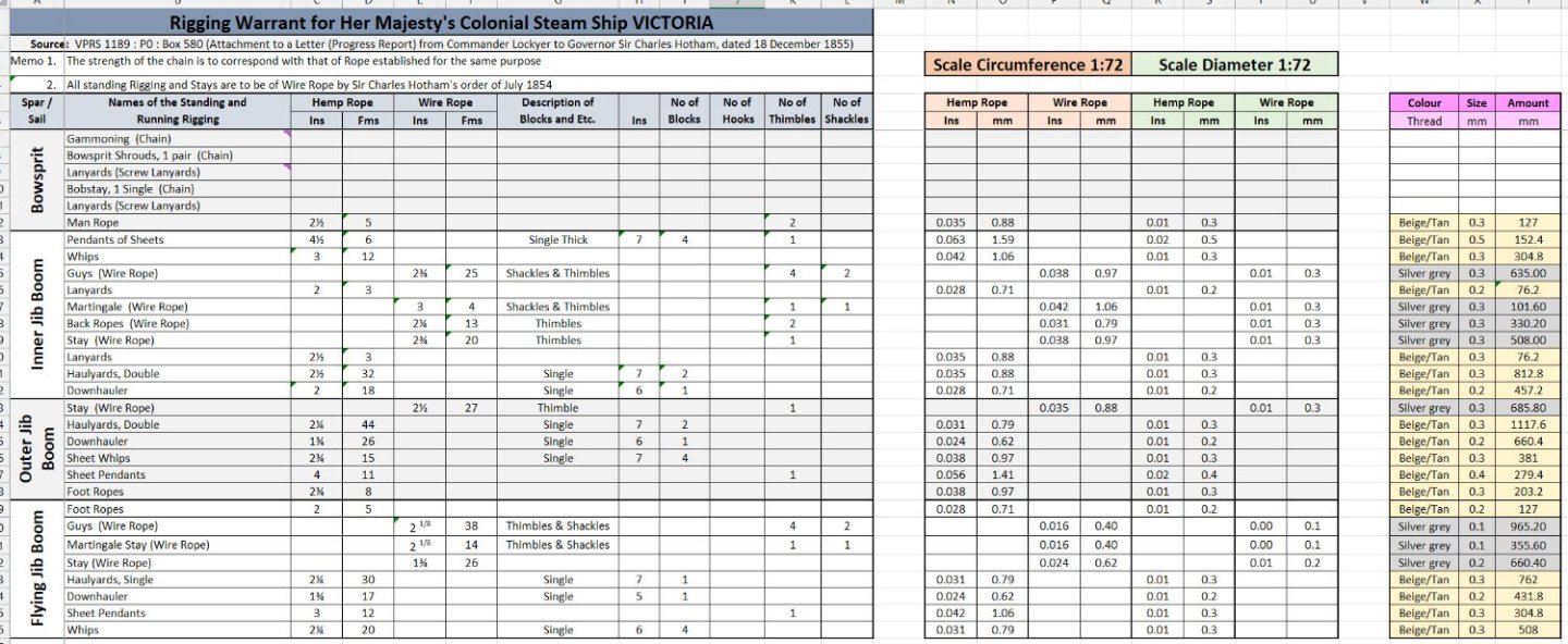
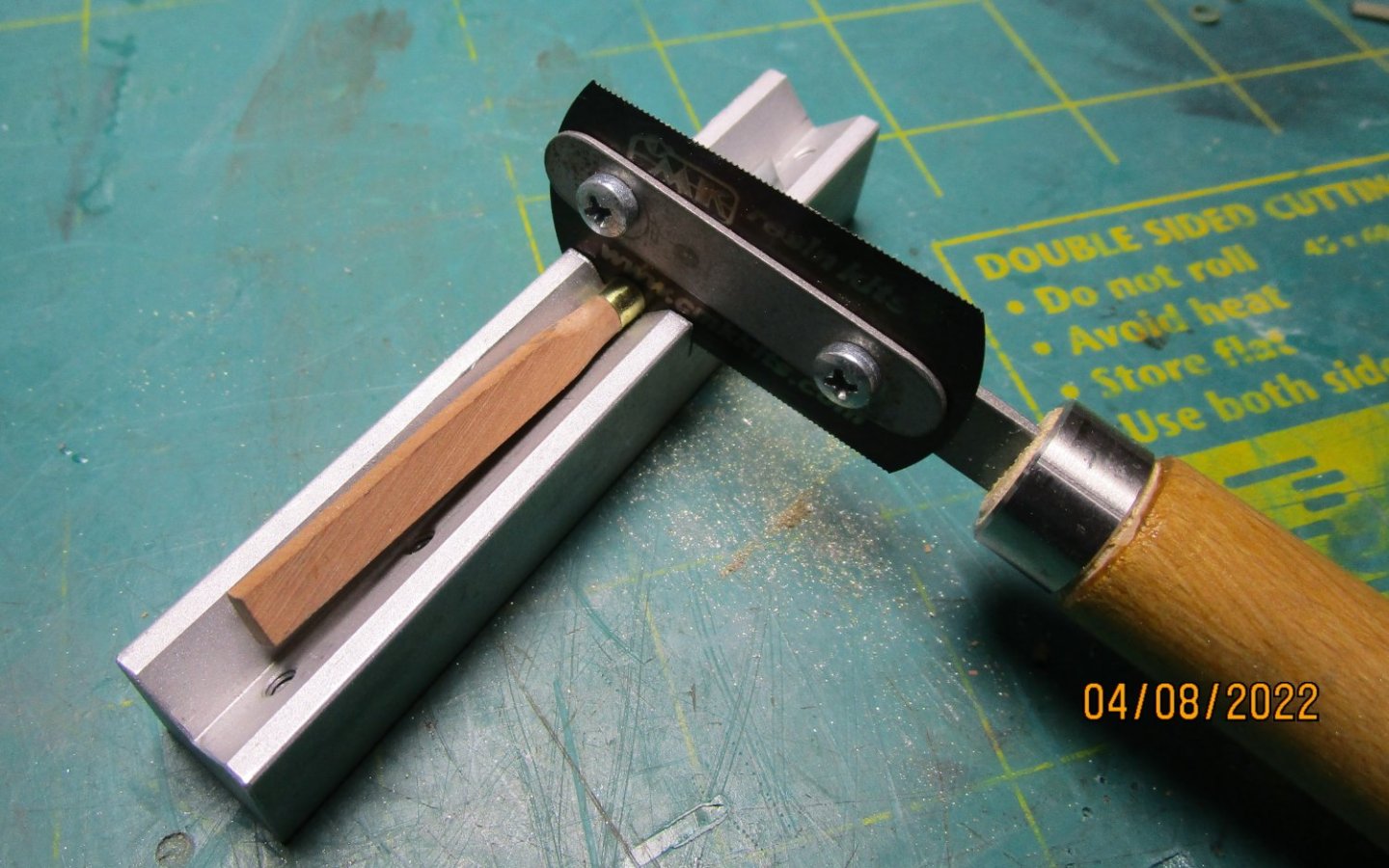
Just a small update, I have been fiddling around trying to determine the best way to make some of the swing boom fittings, and I think I have settles on the way to go. I have found some thin wall brass tube which has the correct ID for the spider band. Using my mill with an indexing head and sensitive drill attachment, I can drill small holes 90 degrees apart using a carbon bit (good bight on the brass). I have made some small eyes with a 0.5mm twisted shank which fit these holes nicely so that I can solder them in place. I then nip and file away any of the eye shaft in the ID of the tube leaving a nice smooth finish that slides onto the boom for a firm fit. The finished band look very acceptable when cleaned up and blackened. For the inner end fitting I have used some PE I had made that when put into a former and domed using a burnisher, provides the base of the fitting. I was having some issues getting the small thin strip to sit properly for me to solder so had to find another solution. I found a bit of thick walled brass tube that had near the right ID to slide over the arms of the fitting but had to ream that out a tad. I then pushed this onto a bit of scrap dowel and put a brass nail in to the end to expand the wood so the tube was held tightly. I then put that into my lathe and cut, filed and polished the OD of the tube to form a very thin wall. Once parted in the small saw jig (micro 'V' mitre box) the inner form could be removed leaving me with a nice thin band. I think the photos show this process but also shows that care needs to be taken even with a jig - one cut got away from me as you can see - the parted tube/band has a very rough edge where my sawing technique was not up to par - luckily I had enough to make plenty of the bands. Now to solder them into place. For comparison, the thickness of the formed base of the gooseneck fitting is 0.2mm and the ruler ticks are 1mm apart. cheers Pat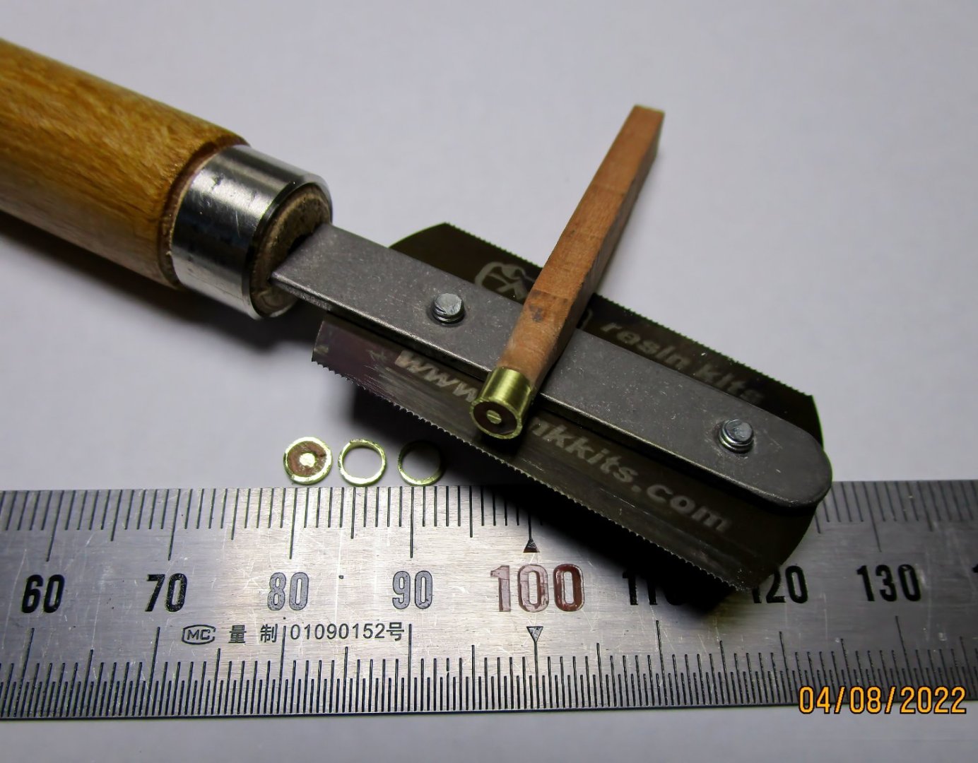
- 1,013 replies
-
- 13
-
-
-
- gun dispatch vessel
- victoria
- (and 2 more)
-
Ditto above comments; just when you think it can't get better than.... well, you continue to provide such lovely detailed fittings. cheers Pat
-
Nice work Rob, some significant progress. cheers Pat
-
Getting there indeed; looks great Greg. You have mastered these now so what is your next building challenge? cheers Pat
- 203 replies
-
- 5
-
-
- Roma
- Micromaster
- (and 4 more)
-
You're making great progress mate; looks good. cheers Pat
- 179 replies
-
- 3
-
-
-
- Second Build
- Pinta
- (and 2 more)
-
I think you have nailed it Dave, some ships I believed had fixed stanchions, but others removeable - the manropes were only fitted as required and usually had a Walkers Knot in the top end that went through the upper ring. cheers Pat
-
Love the planning you put into these micro builds Glen; looks like you have a winner here. cheers Pat
- 194 replies
-
- 3
-
-
-
- Bottle
- Treasure Fleet
- (and 3 more)
-
The boats etc turned out nicely, a lot better than those metal things. More goodies to play with; must be your birthday cheers Pat
- 179 replies
-
- 3
-
-
-
- Second Build
- Pinta
- (and 2 more)
-
we must have crossed in the ether Rob - great minds think alike (well your's might be great at least). cheers Pat
-
Rob, in a similar idea to that offered by NIc, also try some very thin wire as a leader, as it is stiffer than thread. It could be a single strand from the multi-core electrical wire but must be thin. I use ni-chrome wire as it is a little stronger; I simply double it through the leading link of the chain - it is thin enough for for both ends of the wire to easily pass through the block , fairlead etc. cheers Pat
-
HMCSS Victoria 1855 by BANYAN - 1:72
BANYAN replied to BANYAN's topic in - Build logs for subjects built 1851 - 1900
OK, based on the suggestions received, I have gone back though my sources. From what I can see, no contemporary nor more modern authors discuss any sort of a mechanism, resulting in some conjecture in the probable fit. The mechanism will have had to be easy to operate or rig/unrig and of an uncomplicated design. Having swung the boom clear, the crane would then have to be cleared away from the obstacle zone. Accordingly, the first of the best two options being that the entire assembly (crane) could be shipped or unshipped from dedicated fittings or brackets on the hull. This arrangement may have been as simple as horseshoe shaped mating brackets to receive the upper and lower ends of the inner part of the bracket, and locked in place with pins. Whatever the design, the receiving brackets or bolts, and the inner upright part of the crane will have been designed to sit flush against the hull to stop the crane swinging. It was then simply shipped/unshipped as required. The alternative method would be to swing the crane forward or aft out of the way. Again, the crane would need to mate with brackets on the hull, but in this design will have been round spigots, to allow the assembly to swing. This arrangement will have required some form of guys to be fitted which are not evident in any of the imagery and has therefore been discounted. This works, and the added benefit I don't have to try and correct the fitting I have made, as at this scale, the shoes/receivers would be nigh invisible. However, I am still contemplating adding a thin bit of strip brass to the upper end of the upright part of the crane to simulate the upper shoe/bracket. cheers, and many thanks again to all - the power and value of this site is well demonstrated with the excellent exchange of info and suggestions. Pat- 1,013 replies
-
- 5
-
-
- gun dispatch vessel
- victoria
- (and 2 more)
-
HMCSS Victoria 1855 by BANYAN - 1:72
BANYAN replied to BANYAN's topic in - Build logs for subjects built 1851 - 1900
Thanks for the follow-on comments Keith, John and Roger; I think you guys may be onto something there. The boom did indeed swivel in two axis (horizontal and upward to a limited degree). I did not attempt this and have only modelled the horizontal axis - yep you can flay me later The actual swivel joint probably looked like the following, but could have been a simple angled rod (older type) which I have used. Image from The Century Dictionary by WD Whitney 1911. Now if the boom could be got out of the way quickly, the idea of a hinged crane bracket would do the trick. The model I have used uses a rod gusset between the upright and horizontal bracket legs. Now, if this gusset was a simple rod that fitted into a retainer on the vertical leg, and into a hole in the horizontal leg, then it could be easily removed. Now if the horizontal part was hinged in near the ship's side, it could fold inward out of the way. Not ideal but workable; however I would not have much faith in the capacity of the lower bracket leg to secure the boom effectively if the topping lift did not have the weight. Even better might be Roger's idea. If the inner ends of the crane simply dropped into brackets (probably with forelocked pins, the whole assembly would swivel in out of the way. It is not like the crane is supporting a lot of weight; it is more a securing device. Now I really wish this issue had been more evident before I attached the current 'interpretation' of a crane to the model. As it was well and truely glued I think I will damage the model trying to take it off so will have to live with it. I think I will do the other side properly though. Thoughts/ideas? Many thanks again. Pat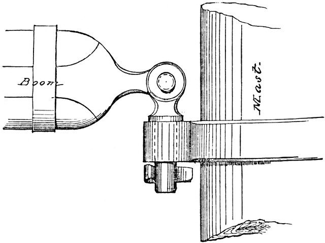
- 1,013 replies
-
- 5
-
-
- gun dispatch vessel
- victoria
- (and 2 more)
-
Lots of new toys to play with Knocklouder - enjoy; as you mention the hardest part is getting the invoice past the bean counters A suggestion, perhaps consider countersinking the heads of those nails holding the mitre box secure so that they are flush with the base otherwise the wider planks may not sit flat for cutting. From the photo hard to determine but you may already have done that. Good luck and happy building. cheers Pat
- 179 replies
-
- 3
-
-

-
- Second Build
- Pinta
- (and 2 more)
-
HMCSS Victoria 1855 by BANYAN - 1:72
BANYAN replied to BANYAN's topic in - Build logs for subjects built 1851 - 1900
I had seen that John; thanks for your follow-up comment. I think the topping lift is the inner one that went to the top lug of the spiderband (about 2/3 of the way out). The other line (cannot recall at the moment) was led via a hole (fairlead) in the bulwark just forward of the chestree (you can see the hole I have left for that in my post 846 earlier - it needs a little more refinement yet). This was done a while ago, and perhaps should have been placed a little closer to the chestree. What looks like the extension of the line to the end of the boom I think is perhaps the upper part of the crane? It is certainly on the same level for that perception to be made?) I think the illusion of it being the topping lift may just be a quirk caused by the aspect the photograph was taken from, and the lack of resolution in the photo. I could be wrong with this entirely, so remain open to all suggestions and possibilities. A 'puzzlement" indeed cheers Pat- 1,013 replies
-
- 3
-
-
- gun dispatch vessel
- victoria
- (and 2 more)
-
HMCSS Victoria 1855 by BANYAN - 1:72
BANYAN replied to BANYAN's topic in - Build logs for subjects built 1851 - 1900
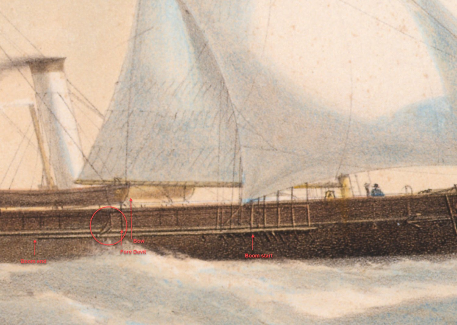
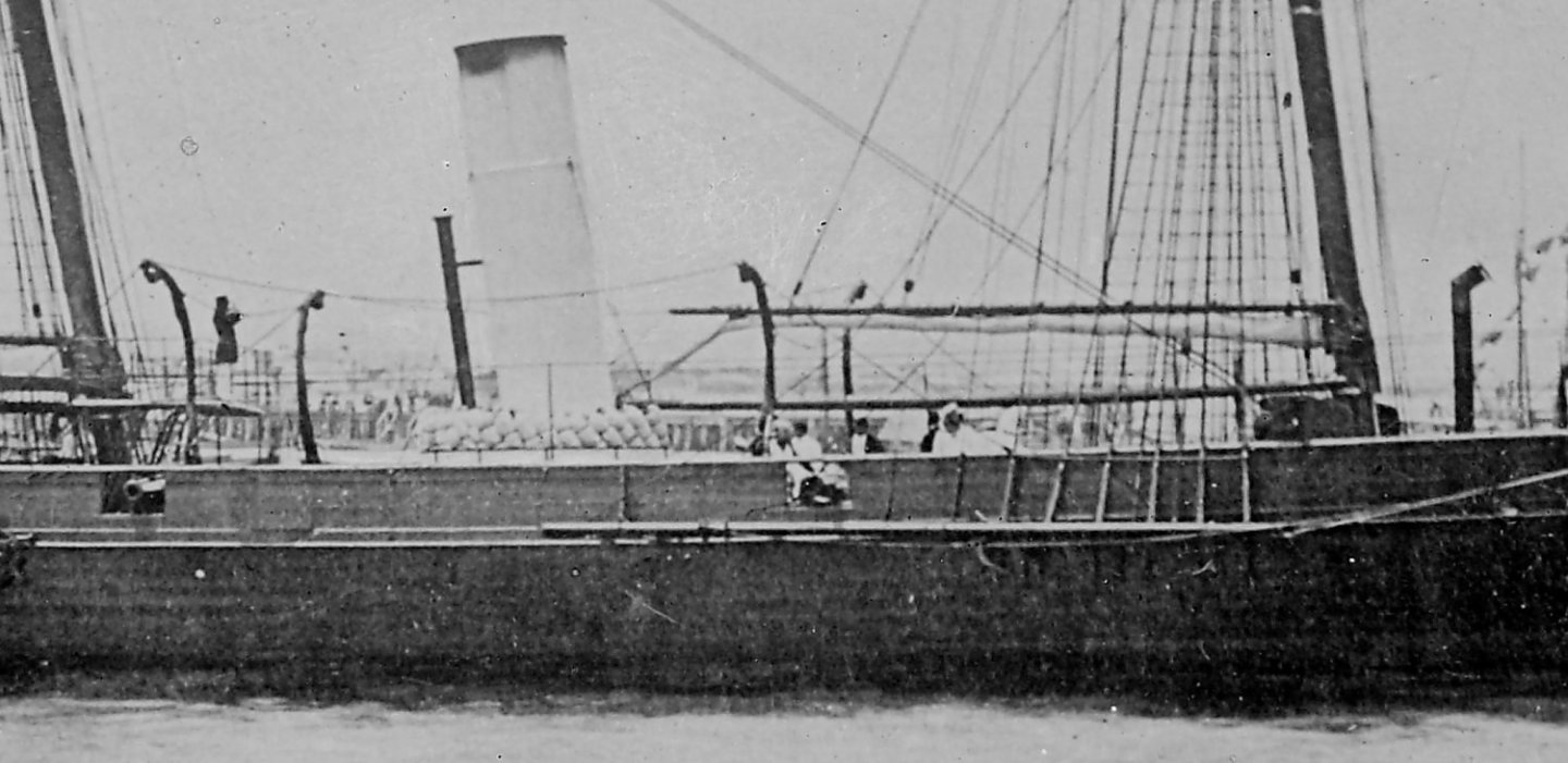
Hi all, again my sincere thanks for the ongoing suggestions and comments - it all helps. This is a little long but the only way to fully explain the detail of the dilemma - sorry. Tony, many thanks for images which aligns with, and sort of confirms the imagery I have. John and Druxey, many thanks - more food for thought. The imagery is inconclusive but I have found the lithographs to be quite accurate and faithful to how she was fitted and rigged (based on the Specification and Rigging Warrant). The images are mainly of her in harbour where typically the booms would be typically fitted ready for use as boat booms. The only clear (ish) image of her under sail does show the boom fitted/rigged while at sea but is a little indistinct. This is a crop of the Lithograph which I have marked up to show the main issues. John, the plans do not show a crane (but I only have an original sheer drawing), but there is a non-associated comment within the Specification that sort of alludes to them. The following images show a large (standing proud of the ship's side) crane the painter has depicted (circled) on which I have based my initial attempt. While clear in the lithograph, it isn't so clear in the photo but on close inspection it can be made out. As you can see, the boat definitely overhangs the end of the boom by some distance. Even allowing for the aspect distortions (painted with artist viewing from fine on the stbd bow - the photo is taken from about the same aspect I think) there are a couple of issues with the depiction (but I am allowing for some artistic licence ). Firstly, according to all of the contemporary and more modern authors, the boom should start near the start of the fore channel (not about half way back as depicted in the lithograph) - this is more evident (the use of the near fore edge) in the only photograph of the full ship. Also, the end of the boom extends too far back in the lithograph. I have made my boom IAW the proportion rules offered by Kipping and Fincham (contemporary Naval Architects) which also conforms with the Specification. The imagery also confirms the boat davit positions forward of the funnel and chestree (with the crane) so I am not concerned with the location and lengths/sizes of the various items; simply concerned with the bow overhanging and getting in the way of the cutter-lifeboat bows. Druxey, unfortunately my concern with your arrangement would mean transferring the weight of the of the boat entirely to the other tackle negating the practicality/fit of the davits in the first place. So my quest continues; cheers Pat
- 1,013 replies
-
- 8
-
-
- gun dispatch vessel
- victoria
- (and 2 more)
-
Real knots verses what is practical for scale ships
BANYAN replied to Srenner's topic in Masting, rigging and sails
I love your sort of 'crazy' popeye2sea. cheers Pat -
I think Jim (Byrnes Model Machines) and Chris Watton have hit the nail on the head - in many cases we should not blame the retailer (in our hobby many are smaller operators such as Chris and Chuck). Rather we should be all putting pressure on the 'greedy' postal services, I take every opportunity when they ask for feedback to give them my 'opinion' (well they asked for it ). We have the same problem here in Australia - ever since the Government put AustPost on a 'profit' driven path they are more interested in making money than delivering a quality service. They have doubled (or more) their delivery times rather than hire more staff; but (and the real kicker) the prices have increased - all so that their executives can be given fancy gifts and bonuses (this in a Government service??). This is the main cause of many good businesses losing international (and some internal) trade. I used to recommend several overseas sources for model related products to new modellers, but now it is just not cost effective to buy these items. I have stopped buying many products unless I can get it/them in Australia as the international shipping costs are now ridiculous (its bad enough for internal postage) - sometimes that means I have to do without and find another solution or product. There are still a very few niche businesses overseas that I will go to (such as Chuck for rope and special blocks), but that is about it. The over zealous profit driven attitude of the postal services (here and overseas) is going to be the ruin of many good business and hobbyists. That said, there are also some businesses that take the opportunity to gouge the customer as has been described (WRT to P&H). These practices are all contributing (along with the general loss of interest in the hobby) in the decline of our fine hobby. I'll stop my rant now Pat