BANYAN
-
Posts
5,964 -
Joined
-
Last visited
Content Type
Profiles
Forums
Gallery
Events
Everything posted by BANYAN
-
 HYW, I am very impressed with the quality of your work and the model, but in this instance I feel that you are reducing the overall quality of the model in not using 'studded" or stud-link chain for your cable. After making that excellent swivel link, I think the cable deserves to be studded? This chain can be sourced reasonably cheaply, but with your skills I think you can make it? The more 'learned' here may be able to offer better advice, but I think English and French (pretty much all) ships were using stud-link cable at this point? Please accept this as a very MINOR criticism/suggestion and I remain an avid onlooker of your very fine work. regards Pat
 -
HMCSS Victoria 1855 by BANYAN - 1:72
BANYAN replied to BANYAN's topic in - Build logs for subjects built 1851 - 1900
Thanks for looking in and the kind comments Eberhard and Rob. Eberhard, I have to admit defeat on this lanyards to date but.... I am still trying. The smallest thread I have still look so out of scale, even the fly tying threads. As these lanyards were not left permanently attached, but drawn from the magazine when closing up to action/battle stations, I may end up leaving them off. My currently battle is imitating the 'cheesed' rope coils on the gun tackles. I could do them separately and attach to te tackle, but it sort of looks wrong, so I am trying to 'cheese' the actual fall of the tackle as per the photograph. Rob, many thanks that is very kind of you to say; not much to look at at the moment as I struggle with finishing the guns - almost there . cheers Pat- 1,021 replies
-
- 3
-

-
- gun dispatch vessel
- victoria
- (and 2 more)
-
Those companionways are looking superb Keith; very impressive work. A suggestion to consider for the flags. Building on John's idea, when I had to do my hammocks at 1:72, I rolled them on a longer length of polystyrene rod (thinnest I could find ofjust under 1mm) this gave them the rigidity I needed but remove the rod before the glue sets up. You could use thin brass rod (0.5mm) also - a very diluted PVA mixture would be less inclined to stick? When dry, I reinserted the rod to give support while I cut to length. Knowing your ingenuity though, you have probably already tried this cheers Pat
-
Wonderful craftsmanship; a joy to see these updates. cheers Pat
-
Looking good Steven; wonderful collection of 'larger' perspective objects you have there in the form of pegs matches etc . You are probably already aware, but please consider sealing that balsa (a diluted pva and water solution works well) so that the glue for your planks is not wicked/soaked into the balsa when you get to lay the planks. cheers Pat
- 740 replies
-
- 3
-
-
- Tudor
- restoration
- (and 4 more)
-
Sounds like a useful tool Rob - any photos details most welcome please. I use a dental micro-motor with a straight and a contra angle handpiece but find the range of tools (2.35mm shank) a little limiting. cheers Pat
-
Looks very good Gary; funny how sometimes you don't seem to have enough hours in the day when you retire cheers Pat
-
Great job on the cleaning Steven, your patience has paid dividends. cheers Pat
- 740 replies
-
- 2
-
-
- Tudor
- restoration
- (and 4 more)
-
Nice to see some progress on her Rob; trust all remain safe? cheers Pat
-
Now that is impressive Keith, very nice set of stairs. Also, thank you again for laying out so clearly the process you take in producing these parts. regards Pat
-
Just when I thought I was kicking some goals you come along to spoil the party Seriously though Eberhard, that is some very (VERY) impressive micro-maching and the result looks excellent. So much for me cobbling bits together to 'simulate' when you can do this at half the size I am doing it at. As you have said in other logs, a machined item looks much better. cheers Pat
-
You have created a very good model cannon there Keith especially noting the scale. cheers Pat
-
Very nice work Keith, I very much enjoy seeing your updates simply to relish the craftsmanship. cheers Pat
-
HMCSS Victoria 1855 by BANYAN - 1:72
BANYAN replied to BANYAN's topic in - Build logs for subjects built 1851 - 1900
Thanks Tony, a nice sharp bit of detail helps to hide the not so perfect Eberhard, the holder is a good idea and could prove useful indeed; I'll tuck that one away for the future. WRT the elevating screw, yep, the Dundas design had the thread cut into the lug; thanks for confirming/pointing that out as I had not thought of it and it makes a lot of sense. cheers Pat- 1,021 replies
-
- 2
-
-
- gun dispatch vessel
- victoria
- (and 2 more)
-
HMCSS Victoria 1855 by BANYAN - 1:72
BANYAN replied to BANYAN's topic in - Build logs for subjects built 1851 - 1900
Thanks everyone for the 'thumbs up' and comments. Appreciate the continued encouragement John, Carl, Eberhard and Keith. Eberhard, 1. WRT the elevating screw, it was made from a small (0.9mm) brass bolt of which I rounded the hex head, then added the handle/spokes. I have yet to determine whether they were bronze or iron. I have decided on bronze based on the research of the HMS Trincomalee. I wrote them as they have a similar arrangement for elevating their carronades and the photos they sent back showed unpainted bronze screws. 2. WRT axletree extension - yep realised that when I painted them I somehow put down the wrong dimensions when I manufactured them. At this stage, I have noted the error but so that I don't damage the carriages, will leave them for this model. They don't look as bad now I have painted the ironwork, but still obvious Thanks for the observation and suggestions; I always appreciate constructive criticism as I learn and improve from it. 3. WRT 3D print process, I will need to get back to you as the actual printing is done by a mate. I research the guns, draw them up[ in 2D and he then draws them up in 3D and prints them for me. I pay for materials and some time and help him with other research. I will ask him the pertinent questions and get back to you. cheers Pat- 1,021 replies
-
- 4
-
-
- gun dispatch vessel
- victoria
- (and 2 more)
-
Despite the tribulations, those decks look good Steven. The colour especially looks very good for decking. cheers Pat
- 740 replies
-
- 3
-
-
- Tudor
- restoration
- (and 4 more)
-
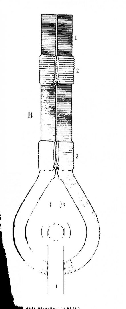
Chris, the attached is for wire rope but I dare say it would not be too much different? cheers Pat
-
Photo Etching - do it yourself
BANYAN replied to Dziadeczek's topic in Metal Work, Soldering and Metal Fittings
Hi Thomas, many thanks for your very informative response which is most helpful. I had no problems with you English at all, so please no need for any apologies. As a matter of fact it is better than mine perhaps and it is my first language I had anticipated a considerable learning curve and a certain amount of wastage in experimenting so thanks for confirming that. I am still not sure which path/method to take/use, but l am leaning towards the photo-resist method at the moment. I will do a bit more reading of Gene's tutorial, and anything else I find on the subject, before deciding on which method to use. I think, to a large degree, this will be governed by the availability of resources, the chemicals in particular. The chemicals cannot be posted/mailed here so I will have to develop a method for chemicals and products I can source locally. Many thanks again, I will now have a much deeper read and be in a better position to experiment. regards Pat -
HMCSS Victoria 1855 by BANYAN - 1:72
BANYAN replied to BANYAN's topic in - Build logs for subjects built 1851 - 1900
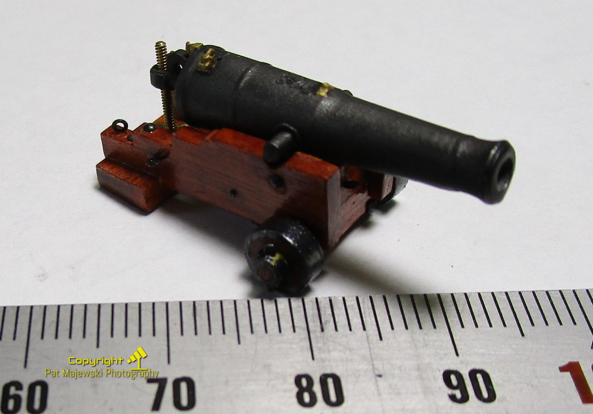
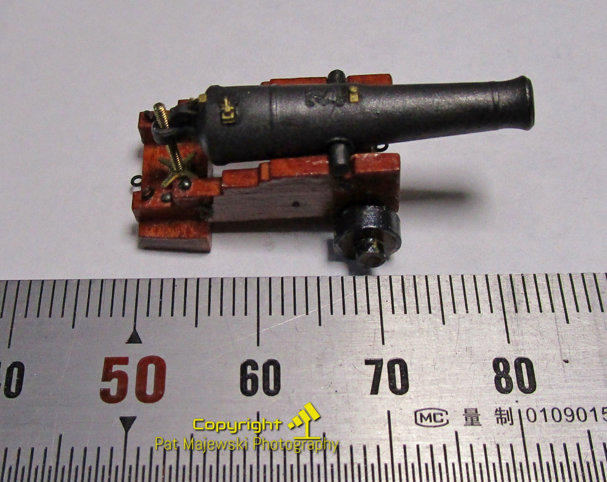
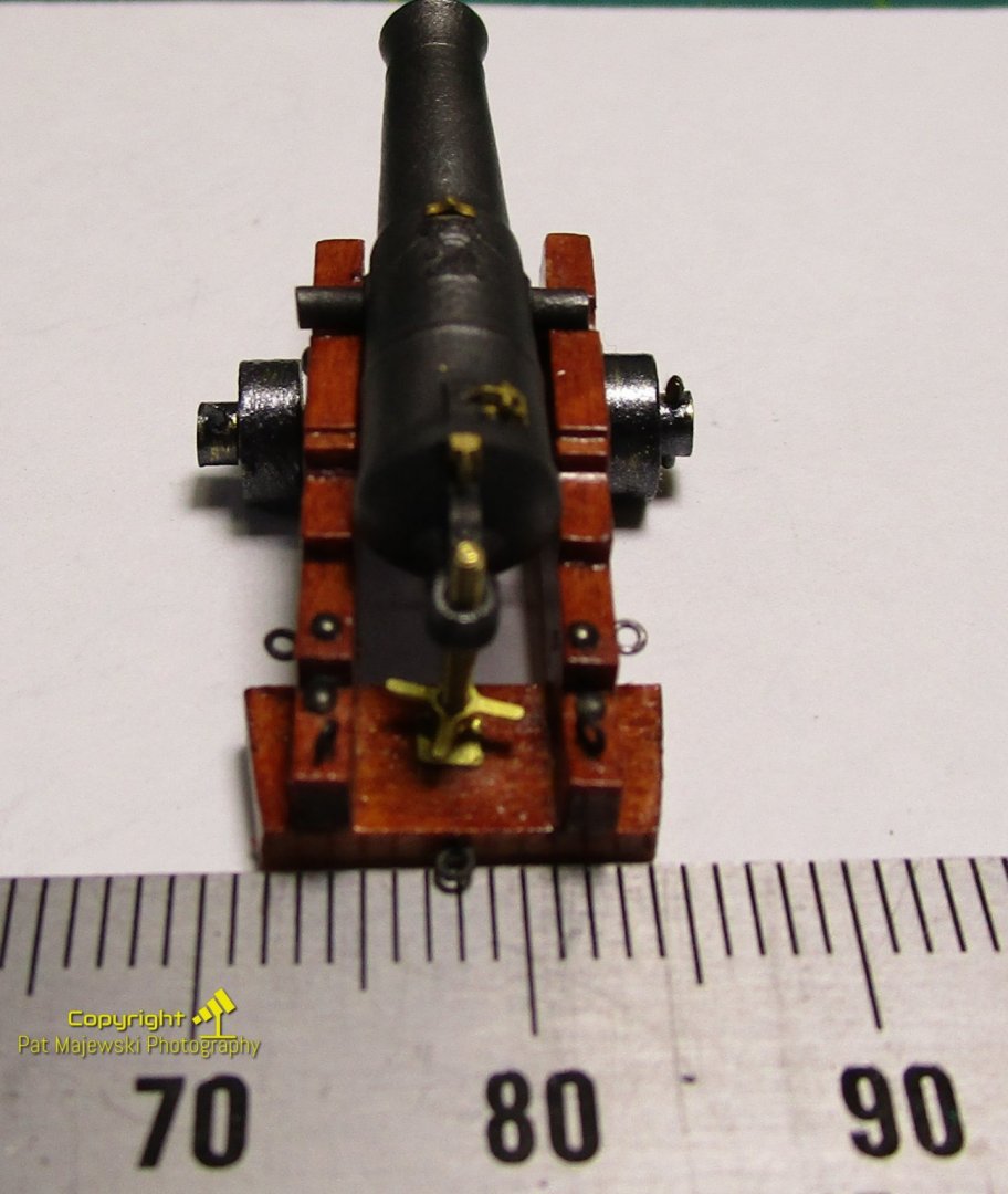
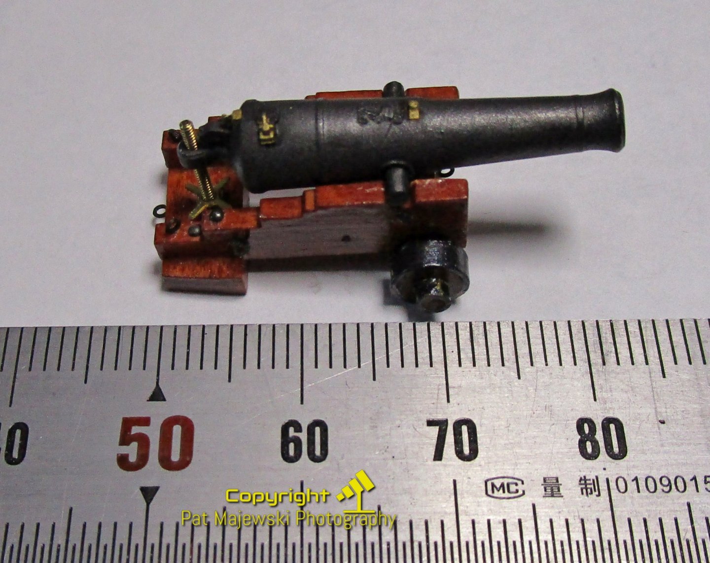
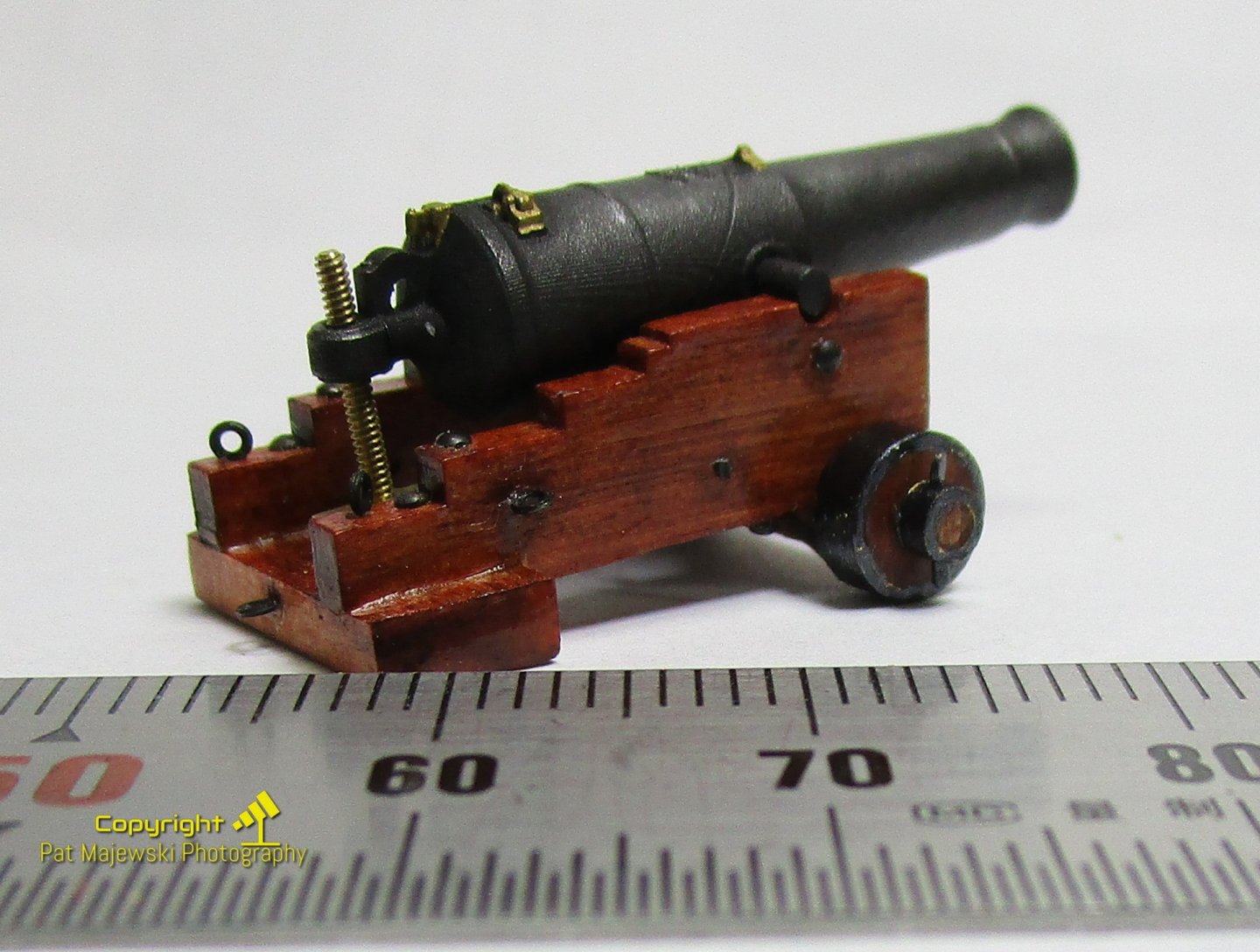
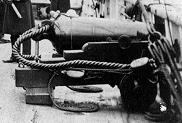
Hi folks, back with another small progress reports. I have started work on completing the armament; 6 x broadside guns - Dundas 32pdr 25cwt on rear chock carriages) and 1 x pivot gun (Blomefield 32 pdr 56cwt on an Improved Ferguson Slide). I have not shown the pivot gun as it is still being reworked a little. I have completed the six carriage (with the exception of blackening the wheels) and I have now painted the gun barrels (were 3D printed). The barrels were airbrushed with Mr. Metal dark iron and I think look reasonably realistic in colour? I started assembling one as a prototype (version 2) to ensure all works. I have yet to do the capsquares over the trunnions, and fit the breeching rope through the cascabel loop. These will be seized to ring bolts before fitting to the ship. The carriage shows the wheels painted but yet to be burnished to remove some of the lumpiness. Please remember these are in very close-up so look a lot worse here than to the naked eye I have manage to get the rear elevating worm screw to actually work, but I would not try this once fitted on the model; hopefully I do not put too much glue on the capsquares to stop the gun elevating/depressing. The barrel is only dry fitted at the moment so it looks a little off-centre. It will be corrected when the capsquares are fitted. I have managed to show a bit of the detail even at this scales including the gunlock, dispart (fore) sight and Millers after sight. I even managed to keep my hands steady enough to paint them bronze without making a real hash of it, but could do with some improvement I will attempt to add a very small lanyard to the lock but I am not holding my breath on that one. and yes, I have files one side of the trunnion bar off-angle but this will be hidden under the capsquare and I do not wish to muck-up the paint at this late stage I have also added a photo of an actual gun fitted in the ship for reference. cheers Pat
- 1,021 replies
-
- 13
-
-
- gun dispatch vessel
- victoria
- (and 2 more)
-
Photo Etching - do it yourself
BANYAN replied to Dziadeczek's topic in Metal Work, Soldering and Metal Fittings
Hi Dziadeczek, Thank you for the interesting post. This is something I am going to try myself in the near future. Is it possible for you to provide some details on the process and the chemicals you used? This would make an extremely useful tutorial and I am sure others also would appreciate it? For example how you transfer the the image to the brass, do you sit the sheet in the batch of chemicals, or hang it or raise it off the bottom with posts etc etc. Your gingerbread turned out very nicely, clean sharp edges. What size brass plate did you use for this - 0.3mm? Also why did you include the ruler/scale - was this to ensure no loss in accuracy when transferring? Stay safe, best regards Pat -
HMCSS Victoria 1855 by BANYAN - 1:72
BANYAN replied to BANYAN's topic in - Build logs for subjects built 1851 - 1900
Thanks all for your continued interest, comments, suggestions and 'likes'. Eberhard, I agree about files etc on 3D printed object; especially this media as it makes the problem worse rather than better in these very small items. That is why you see the small bumps on the pedestal (not visual to the naked eye) and gather sparked your comment. I remember you discussion on those 'separation strips' from another log but had forgotten them - I think I need to find some and possibly invest in one of those so called 'bow' sanders plastic modellers use a lot. I am still debating whether to leave dobs to represent the black 'writing' in the EO; or, should I try to break it up a bit with white to try and break out individual characters?, Unfortunately being 3D printed I could not insert a card in this EOT, but I like the idea Drixey and Eberhard discuss. I used something similar for the rudder/wheel telltale (shown in a much earlier post). cheers Pat- 1,021 replies
-
- 3
-
-
- gun dispatch vessel
- victoria
- (and 2 more)
-
And, will help considerably with identifying the your rigging details for the ship. Nice catch! Very nice work on the Parrot guns; you would never know that was wood. cheers Pat
-
Nice adaptions Eberhard, I get tool envy every time you post one of these beauties cheers Pat
-
HMCSS Victoria 1855 by BANYAN - 1:72
BANYAN replied to BANYAN's topic in - Build logs for subjects built 1851 - 1900
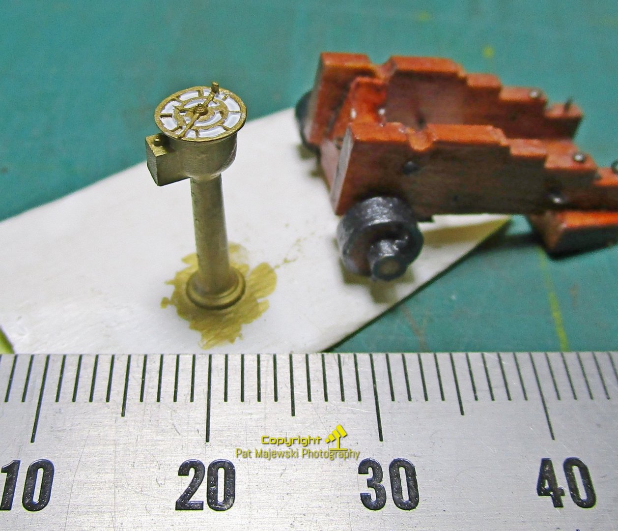
Hi all, shown below is my first attempt of the EOT. This was 3D printed and is only 11mm high with the panels in the Engine Order face less than a mm wide and about 1.5mm long. This is extreme close up so shows a lot of bumps etc that are not visible to the naked eye. The Mr Metal "Brass" has yet to be polished which will smooth these out somewhat. the dabs of black are supposed to represent order positions (slow ahead, half ahead, full ahead etc). At this scale and my shaky hands this is the best I can achieve and looks OK to the naked eye. The second photo shows the EOT and one of the gun carriages with the brass wheels painted with Mr Metal "Iron"; again they need to polished and unfortunately, the photo implies the lot is painted but the wood of the truck is not painted, nor is the internal part of the axletree stub. I will try to get a better photo. cheers Pat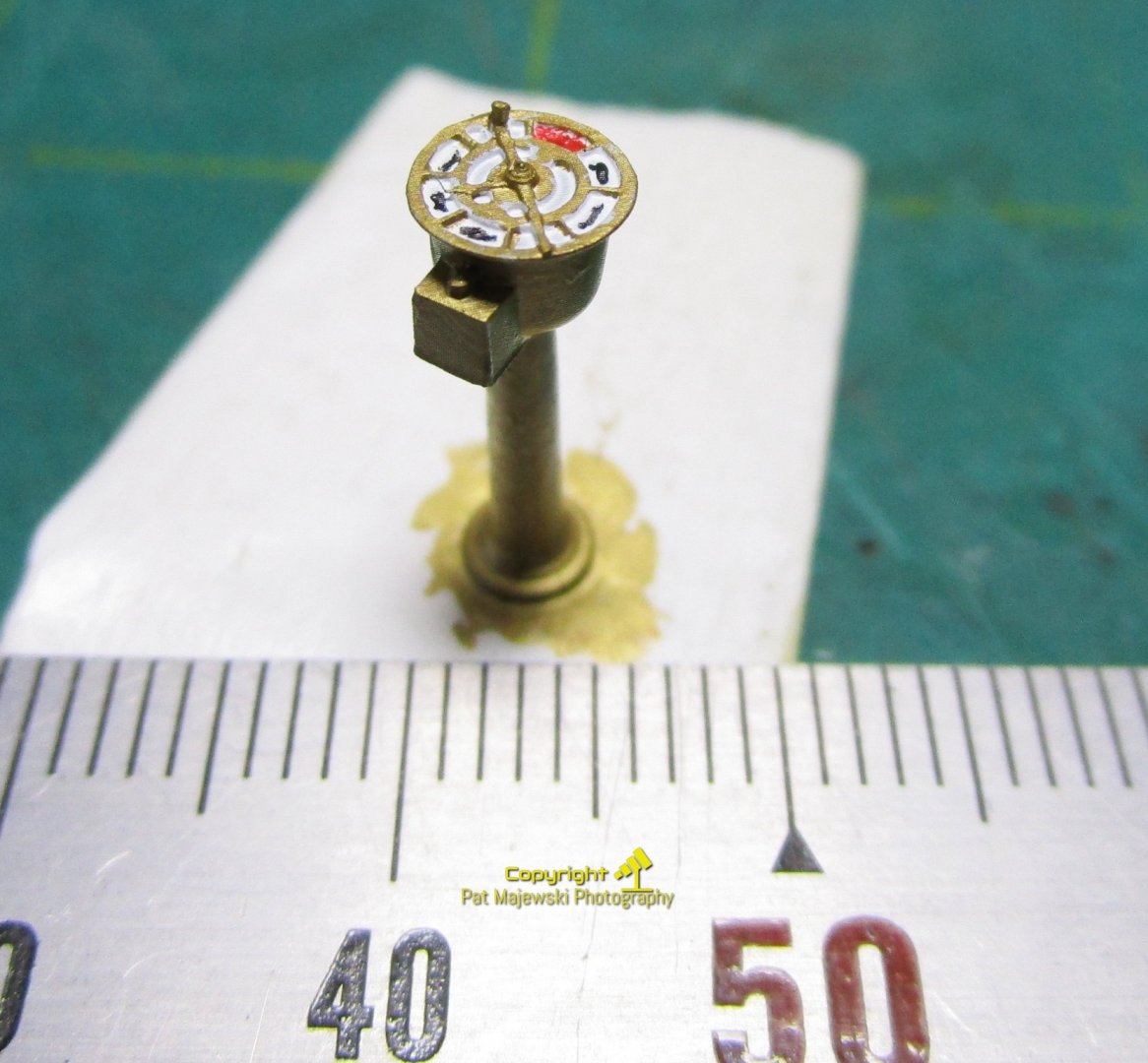
- 1,021 replies
-
- 12
-
-
- gun dispatch vessel
- victoria
- (and 2 more)