
HOLIDAY DONATION DRIVE - SUPPORT MSW - DO YOUR PART TO KEEP THIS GREAT FORUM GOING! (Only 53 donations so far out of 49,000 members - C'mon guys!)
×


BANYAN
-
Posts
5,941 -
Joined
-
Last visited
Content Type
Profiles
Forums
Gallery
Events
Everything posted by BANYAN
-
 Excellent craftsmanship (as usual) Keith; I think you would have no problem finding a job as a Master Metalsmith in any dockyard (new or old) cheers Pat
 -
Nice little 'home' for your creation you are assembling there Rob; look forward to seeing it complete. cheers Pat
- 1,208 replies
-
- 1
-

-
- great republic
- clipper
- (and 1 more)
-
Very nice work Eberhard; they came up very well indeed as the inner and outer alignment appear 'perfect'. What is the masking film you have used as the straight/levelling edge please? cheers Pat
-
Looks great Steven, and those oarsmen really set it off. As to my earlier comments, I was referencing the lining not so much a waterway. I think that a waterway as you have used it is the way to go. cheers Pat
-
Thanks for raising this Mark, and for opinions expressed by other forum members. This is very useful information and while I am in no position to contribute, I will certainly file this way. cheers Pat
-
Just show them the John Cleese 'Meetings B......y Meetings short movie - John Nice progress albeit slow; the planking looks very good. cheers Pat
-
But where's the lock and key? Just kidding - darn that is some lovely work; you Sir are a magician with brass. cheers Pat
-
Steven, not sure if a waterway would be necessary? If water was getting onto the upper deck, then would it not also flow down through the more central spaced planks also? Yes,, if sufficiently heelied, it may take the water to one side but how often would that occur if being rowed? If they had to cope with that, surely it would have coped with water from the edges also? More experienced people will provide better / more appropriate answers, but this is just offered as a 'thought' cheers Pat
-
Remarkable indeed, especially at that scale. Very nice detail achieved in something so small. cheers Pat
-
Hellppppp! someone pick me up off the floor. I am still stunned with the level of machining and manual skills you display here Michael. Between you and KeithAug, a collation of your various works would make the best Video/Image based tutorial for us 'apprentices'. That is some excellent work! Thanks for taking the time to document your processes. cheers Pat
-
That will look very good Rob and a great way to show off the model. cheers Pat
- 1,208 replies
-
- 1
-
-
- great republic
- clipper
- (and 1 more)
-
Test of Byrnes table saw
BANYAN replied to michael101's topic in Modeling tools and Workshop Equipment
One thing that can be said of Jim's tools is that they are checked for true and tolerance before he ship's them. I don't think I have found another tool that is so well 'tuned' straight out of the box. That is not to say that shipping etc may have caused a small misalignment, but that would be unusual also as the tools are well packed - mine survived the trip to the other hemisphere unscathed. As Jim himself has identified, and Druxey suggested, the fence has a deliberate offset abaft the blade's arbor to ease the passage of the stock and cut piece. This is necessary as there is no riving knife/blade fitted to stop the wood binding abaft the blade, and this works well. I have cut planks from either the outside of the stock or the inside with no issue if you lock the fence as recommended (front first) . This will NOT cause the tool to cut out of true if as others have suggested you have checked the blade is correctly mounted. The saw is designed such that if the stock is fed in parallel then it will cut straight straight, and will not bind on the stock unless you get a large build up of sawdust for some reason. One major problem I encountered, until I realised what the issue was, is that the very fine slitting saw blades may flex when cutting thicker hard wood stock. All that said, I think the blade angular difference you see is this offset/easing. Only testing by cutting some stock and checking the trueness of the cut will confirm if you have an issue or not. Jim can manufacture a jig using a dial indicator to check parallelism if the need arises. If after checking your blade alignment etc, and measuring the cut stock with a vernier or micrometer etc for trueness and consistency, and you still find it is not cutting parallel, I would recommend you get in touch with Jim direct. He is very helpful in sorting these issues. cheers Pat -
Very nice work Al, those masts, and especially the chainwork for the Martingale/Dolphin Striker looks superb. cheers Pat
-
I thought there was something in the database Rob, but unfortunately I cannot find it. I remember a member writing a mini-tutorial of sorts when he built his case. I will have a look and see if I can find it as he asked me to have a look at way back as a potential article; may not have been hosted/posted. I did a quick search on glass cases and a lot of interesting posts came up, which may be of some use. cheers Pat
- 1,208 replies
-
- 1
-
-
- great republic
- clipper
- (and 1 more)
-
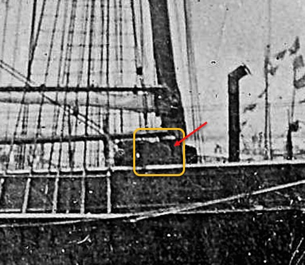
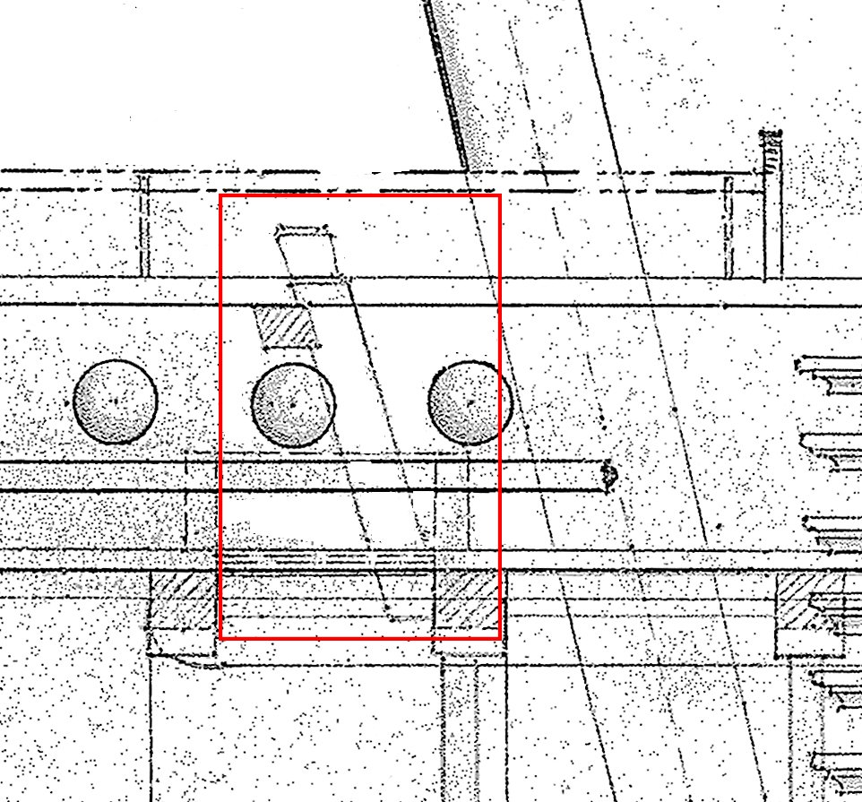
Hi all, further to previous posts, I have established from Fincham (a contemporary author, and probably known by more experienced in rigging practices), that at least in this period, the jeer bitts were generally positioned abaft, and Topmast Sheet Bitts before the respective masts. This accords to the imagery I have showing the rigging, namely that clew lines etc are shown with the falls etc before the masts. This arrangement supports the fact the lower yards were stood well proud and forward of the mast with the use of iron patent parrels/trusses, and that the fitting of the fore and aft sail booms would require a clear arc of operation abaft the mast. Additionally, the masts in this ship were raked much further aft than usual practice, being 5, 10 and 15 degrees for the Fore, Main and Mizen respectively. Accordingly, my assumptions, at this point, are that she had Topmast Sheet Bitts before the Fore and Main masts, and although positioned abaft the Mizen, that pair of Bitts served a different purpose (established from the imagery) as 'Victoria' did not carry a crossjack (Specification and Rigging Warrant confirm this). Also based on the limited amount of detail in the profile photograph, a crop of which is shown previously, I believe a Gallows was fitted abaft the Foremast, with the forward end having the belfry mounted on top and a lifering fitted either side on extended rails. Goodwin, page 220, provides the scantlings and heights etc for the Bitts and crosspieces; and Fincham advises that, in this period, the gallows cross piece upper surface was generally 5 feet above the deck planks (which generally conforms to Mark's advice above). I will continue to use 8 inches square ad the scantling for the Bitts themselves, as this conforms to the size drawn in the contemporary Arrow and Vigilant Class plans, and as determined from the photograph. The latter being derived by the approximate median sizer of the planking transposed upon the bitt size shown in the photograph of the crew on the after upper deck. Also from the 'Specification' I have established 'Victoria' had "handsome end boards to the Gallows", and that a 100 gallon freshwater (FW) tank was to be fitted on the upper deck (location not specified). I think the dark 'mass' evident in the photograph crop may be this FW tank, as this is realistically the only place it could be fitted without interfering with the operation of other fittings or rigging. As such, I think the Gallows acted as a the supporting external frame (exo-skeleton) for this FW tank. A 100 gallon tank, sized to fit in this space will have had the top part higher than the cap rails/bulwarks to accommodate that volume. I would appreciate any further thoughts on my assumptions, and any errors of deduction I may have made. cheers Pat
-
Thank you very much Mark, much appreciate the information. I will assume then that one of the Bitts, probably the Fore mast, was fitted with a 'gallows' which i am also assuming will be separate to the Belfry. I am starting to develop an idea that the Fore Bitts had a crosspiece, a gallows and the Belfry was on top of that. The attached is from one (of two) the lithographs of the ship I have which shows the Belfry perched higher then the Bulwarks. The fore-and-aft attitude of the belfry may be a perspective thing. A profile photograph of the ship (built 1855) taken c1868, which I have cleaned up a little shows a life ring and much other gear aft of the Foremast. Note from the photo that may be possible the belfry did sit along a fore-and-aft gallows? There certainly was a lot of gear just abft this mast. It is also like this area housed a 100 gallon iron freshwater tank (specified in the Contract and this is the only real place it could befitted without interference with other eqipment/operations (BUT I am possible - no probably - wrong with that too The third image is a crop of the Vigilant class Gun Despatch Vessel "Alacrity' c1856, and shows the rake aft of the bitts in these vessels. cheers Pat

-
Lookn' good Rob, nice work. certainly on the homeward bound leg of this building journey now. cheers Pat
- 1,208 replies
-
- 2
-
-
- great republic
- clipper
- (and 1 more)
-
Stunning work on those 'gold plated' ground tackle fittings Keith Miniature working versions and they have cleaned up beautifully. Do you give them a bath in 'pickle' or other solution to do this or simply polish with files and stone etc? cheers pat
-
Hi all, in urgent need of advice and suggestions from our more experienced members WRT Sheet Bitts. 'HMCSS Victoria's' Contract (Specification) calls for Top sheet Bitts to all masts, then in a separate area calls for "Gallows, Cross pieces and Bitts". There are several questions here which I list below but first some background. Firstly, there no scantlings are provided. Secondly, the only upper deck photos shows the Mizen Bitts only, and this pair do not have cross pieces, or stub cross pieces. Thirdly please note these are for Top Sheet Falls/pendants. Lastly, the photo shows a set of 'horns' or 'thin ears at the top, rather than knightheads, which are used for belaying, and the fitting of a cleat to the inboard face of the Bitt. Also, each mast was fitted with a Spider band for belaying pins. Contemporary plans for the Arrow and Vigilant Class Gun Despatch Vessels (GDV) show cross pieces fitted to the Fore and Main mast Bitts and stand individual Bitts for the Mizen so I am assuming this will have been the fit for the 'Victoria' also as she is very much based on these types of vessel. From these plans I have ascertained the molded size of the Bitts will be 8 inches. Now the questions: 1. The plans for the GDVs have the fore and Main mast bitts fitted at significant inclination aft of the vertical; I am assuming to allow a more direct belay as the masts are inclined aft more than usual. Will this angle have carried on below deck or straightened to be more vertical. 2. Any ideas on how high these would be? The Bulwarks are only 2 ft 6 inches and the tops of these are about level with the them and the waists of the men. This would make them about 3 feet but this doesn't accord with other descriptions (though for earlier ships). 3. Would the riser timbers be 8 inch square? 4. Where would the Gallows been fitted as the wording implies they were part of the Bitts? Nothing in any imagery, she did not carry boats internally etc. Is there another meaning/definition for "Gallows" (as in Fife rails?)? cheers Pat
.thumb.jpg.1ddc05a9118719de64f1eeaca5423307.jpg)
-
Thanks very much Michael, stow that away as well. I had to look twice at the cabin paneling with the cushions in place; I thought it was the real 'McCoy' you were using as a reference, not your scale version. That is impressive! cheers Pat
-
Hi All, I had the pleasure of seeing this model 'in the flesh' today , and photos do not do it justice - the paint work is very rich and the model, as a whole, is going to be a very fine example. Thanks for hosting me Steven. cheers Pat
-
Beautiful joinery Michael, a master carpenter couldn't do better. Those screws look great; any chance of seeing the 'formula' or process you settled on? cheers Pat
.jpg.64bb87f399fe4dfa390cf2c63ca71ac0.jpg)