Snug Harbor Johnny
-
Posts
1,509 -
Joined
-
Last visited
Content Type
Profiles
Forums
Gallery
Events
Everything posted by Snug Harbor Johnny
-
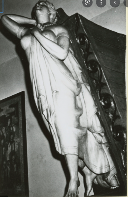
 'Good observations on the figurehead, to be sure. A photo nearly from the front in the India House shows the left foot forward concealing the right from that perspective. Yet an image (from p.9 of this log) at nearly the same angle shows the right foot 'crossed' behind the left. This image appears to be an artists impression as explained below. A picture of the India House figurehead from a lower point of view and a different side angle - the point of view of persons walking up the stairs of the India House (and likely the artist) - gives the illusion of the 'crossed' foot ... when it is in reality well behind. Ergo the artist put that into the painting as he saw it from below, yet he also wanted to portray the body from a higher perspective. Arguably, one can see differences in the drapery on the left leg between the India House figurehead and photos of the figurehead on the Glory late in her career. Yet there is convincing provenance that they are both one in the same ... with significant restoration and rehabilitation lovingly done between the time she was at the prow of the Glory and her installation in the India House. We know that the Glory was McKay'slast clipper ... and his masterpiece. We know of her career as well. Documentation held by Hyland Granby Antiques (the present owner since 2021 - Lord knows what they had to pay to get this masterpiece) show that James A. Farrell, president of U.S. Steel in 1923, bought the figurehead prior to the ship's destruction that year. Farrell was one of the founders of the India House, to whom he gave the Glory's figurehead after restoration. Richard C. McKay wrote a preface to a book in 1927 that James Farrell had always been interested in Donald McKay and his ships, especially the Glory of the Seas - which his father, Captain G. Farrell commanded and sailed with young James Farrell around the Horn. Farrell was not just a wealthy collector, but a lover of the Glory from his youth. He was intimately familiar with the ship and desired to save her most beautiful feature - not for himself, but for the public to view and appreciate for what (he thought) would be in perpetuity. Obviously, expert repairs at Farrell's expense were done to reconstruct the missing arm and foot, removing many layers of paint in the process. And it seems most likely that any previous remodeling or repair of the leg drapery in question (perhaps evidenced by blocks or pieces of added wood not original to the sculpture - sometimes found in figureheads or 'cigar store' figures) was corrected in a manner consistent with the exquisite artistry evident in the surviving original work - most of which survived intact. We are lucky that James Farrell was as sentimental and forward-thinking as he was. Johnny EDIT: 'Came across an old newspaper article (too long for everything here) that shed some melancholy light on the subject figurehead (among other aspects of the Glory). 'Brough a tear to my sentimental eye, it did - so I'm adding it here as related by the reporter from the 'old salt' who told the tale. I have no reason to disbelieve it, but if not entirely true - it ought to be. Exerpt from: Transformation of the Clipper "The Glory of the Seas" By Woodbury S. Brintnall (Article appeared in the newspaper: San Francisco Call – vol.110 number 116, 24 Sept. 1911) Of the ships that pass in the night are told many tales passing strange. At night, when outgoing waters of an ebbing tide pull on straining hawsers, you may listen to this—the story of a once proud and mighty ship. You may come to know of the sailor, John Martin, and his sweetheart, long since dead, whose beauty yet lives in the figurehead of the last of the clipper ships, “The Glory of the Seas.” “It looks as though it had a history,” I suggested to the old sailorman, as an opening wedge. “It has,” said he. “Her name was Elizabeth—Elizabeth le Forgue,” he said, “and I guess that even she don't care—any more. There's a bit of a story about that figurehead, too. It was done from life. But lord, even the man who carved it, he's been dead years." "When the Glory of the Seas was launched she was, folks said, the most likely lookin' girl in East Boston. You see, she was to marry him, John Martin, when he come back from the ship's first voyage ’round the Horn to ’Frisco in ’69. He was a likely lad—a little wild, perhaps, and he didn't go back so soon as promised. There was people said she did it a purpose, and some said it was an accident, but, anyways, she was drowned off one of her father's fishing boats, and when the sea gave up its dead—one of her arms was gone.” The moon shone down on the figure of “Elizabeth”—Elizabeth le Forgue. She had but one arm! “And this figurehead,” I exclaimed. “I'm telling you,” answered he, “it's curious like, but the day the girl was drowned the sea was running strong, and when it cleared, the ship's figurehead had but one arm. Course, sailormen are superstitious—but they've never fitted one since that has stayed on. Martin, he sailed some voyages after, and the men aboard mostly thought him queer because he was always a working on that figurehead, beautifying Elizabeth. Sort of duty it was, with him, I guess. He was lost overboard in the eighties in a storm— and ever since she's had but one arm. The company, they don't care—it's knives and grinders now, and salmon and dollars. And tomorrow we'll leave, and pretty soon we'll smell to the high heavens of salmon. I guess ‘Elizabeth’ don't much care. Good night.”

- 3,560 replies
-
- 3
-

-
- clipper
- hull model
- (and 2 more)
-
Just now, an afterthought hit me on the attachment of the forward rowing oars! The way I did them - which is the way in the kit instructions - doesn't make for effective rowing, since the pivot point needs to be at the gunwale for the oars to dip low enough to be effective. THAT is why the original had (as recovered from the Giza boat tomb) those 'bundles' of rope that made a 'column' arrangement that went out to the gunwale where the oar handles were attached. So how to do that? .... The simplest way to approximate effectively is to tie a 'hangman's noose' having a wrapped portion of the length needed to go from the deck beam to the gunwale. To give it enough body (strength), the noose would be made with 4 ropes (but tied in the same way as an ordinary noose. The noose would be snugged on the oar handle, and two of the four ropes would be passed through the slot in the deck beam - then tied to the other two. Hmmmmm, I suppose I could go back and revise those oar attachments at some point - perhaps when I do all the figures. If so, then I can add a final picture to this log ... a sort-of epilogue. EDIT: Since the deck beams are higher than the gunwale, when extended - the oars DO have enough downward angle for the blades to engage the water if the oar handles are lashed to the deck beams per instructions. But the handles will drag along the gunwale (eventually wearing grooves) and the oars can't be arranged with the handles high as seen in the museum (a way to ship them keeping the deck clear) without the rope bundles to move the pivot point to the gunwale. I'm likely to leave things as they are, as the appearance is OK - and I want to work on other projects. This build has been a great learning experience ... as with all builds. Johnny
- 63 replies
-
- 3
-
-
- Finished
- Khufus Solar Boat
- (and 1 more)
-
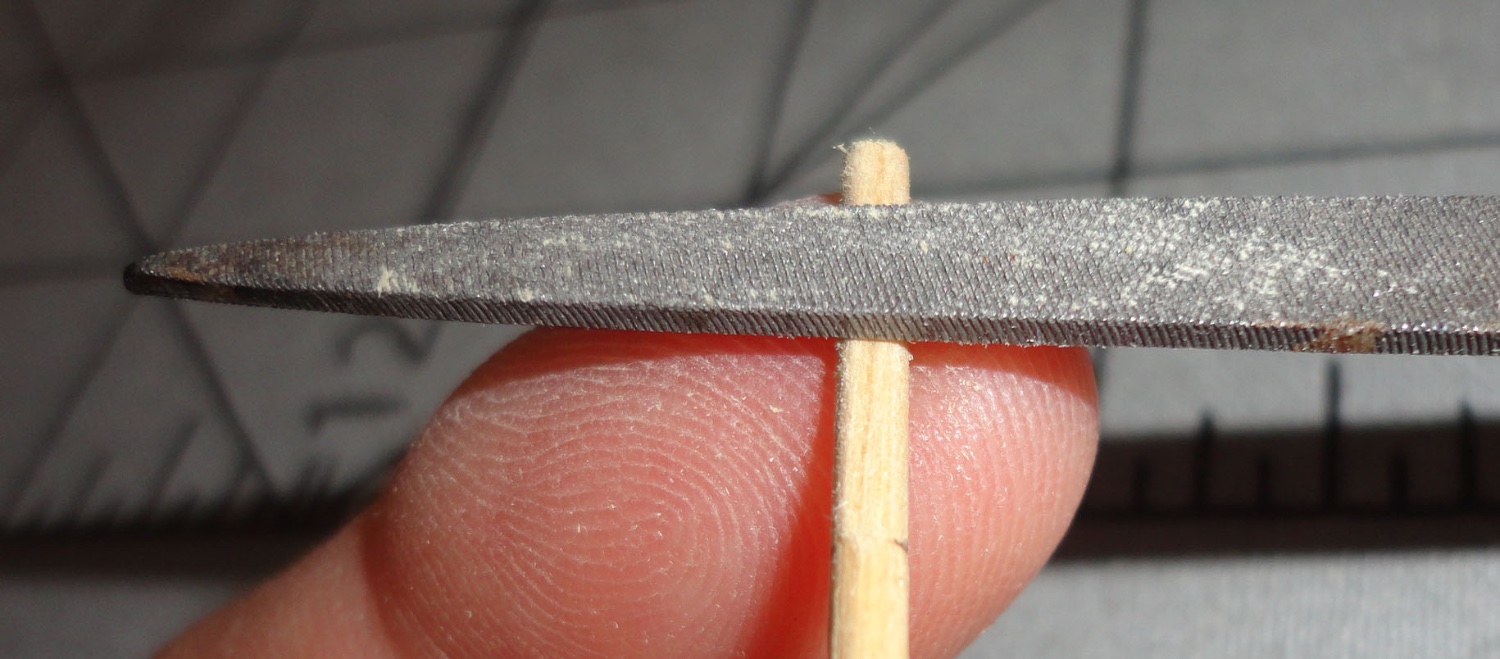
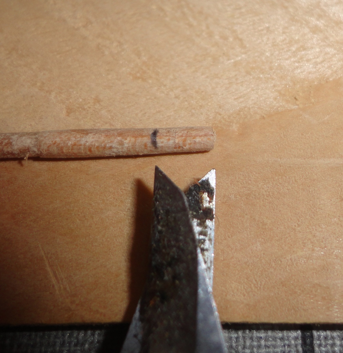
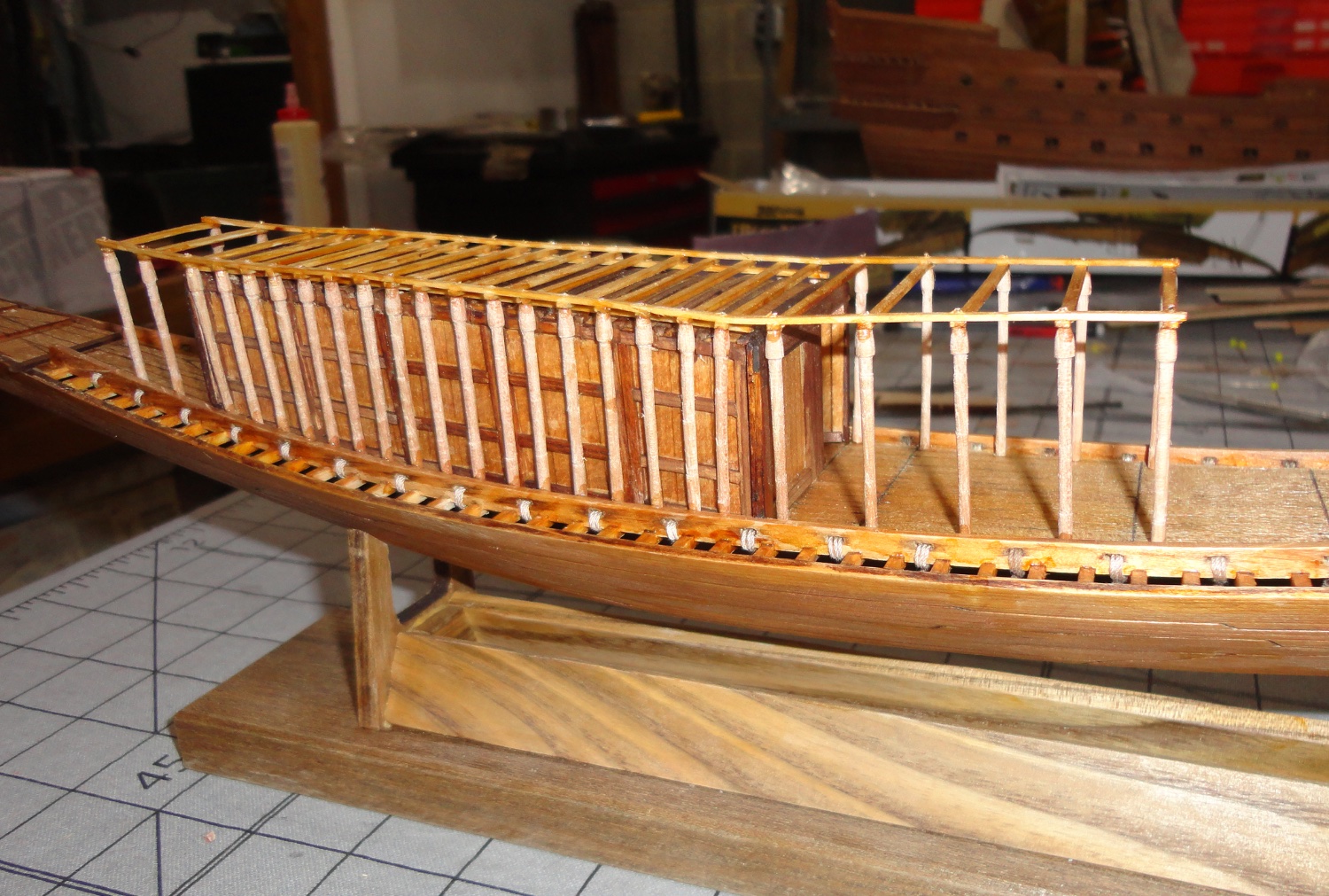
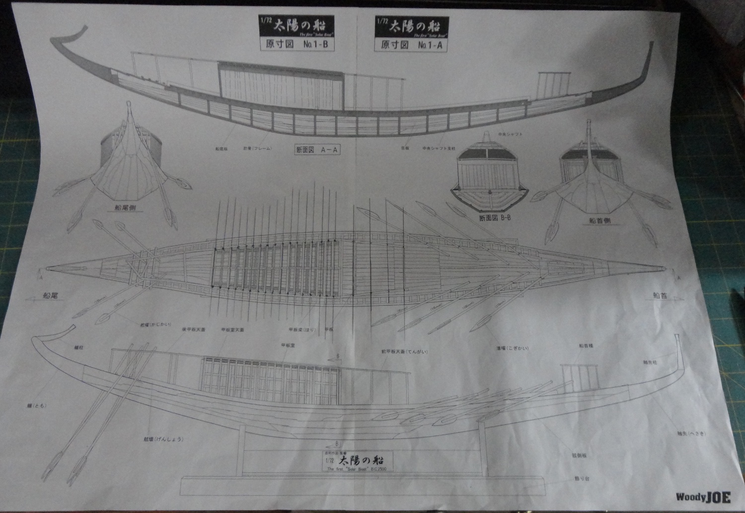
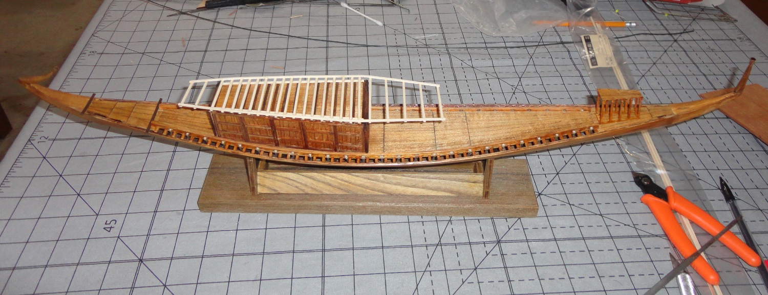
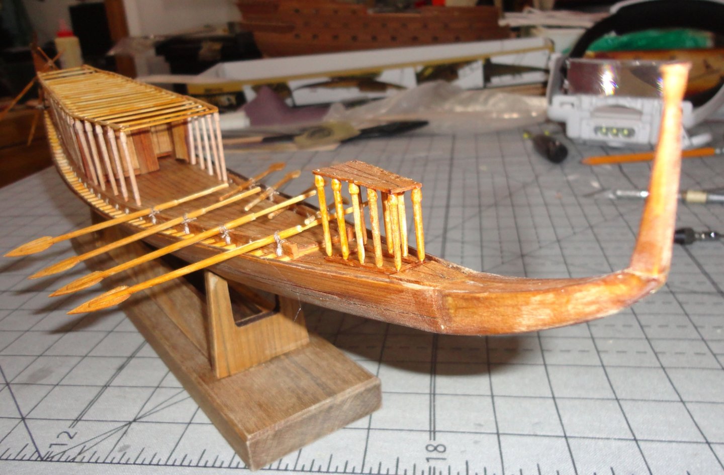
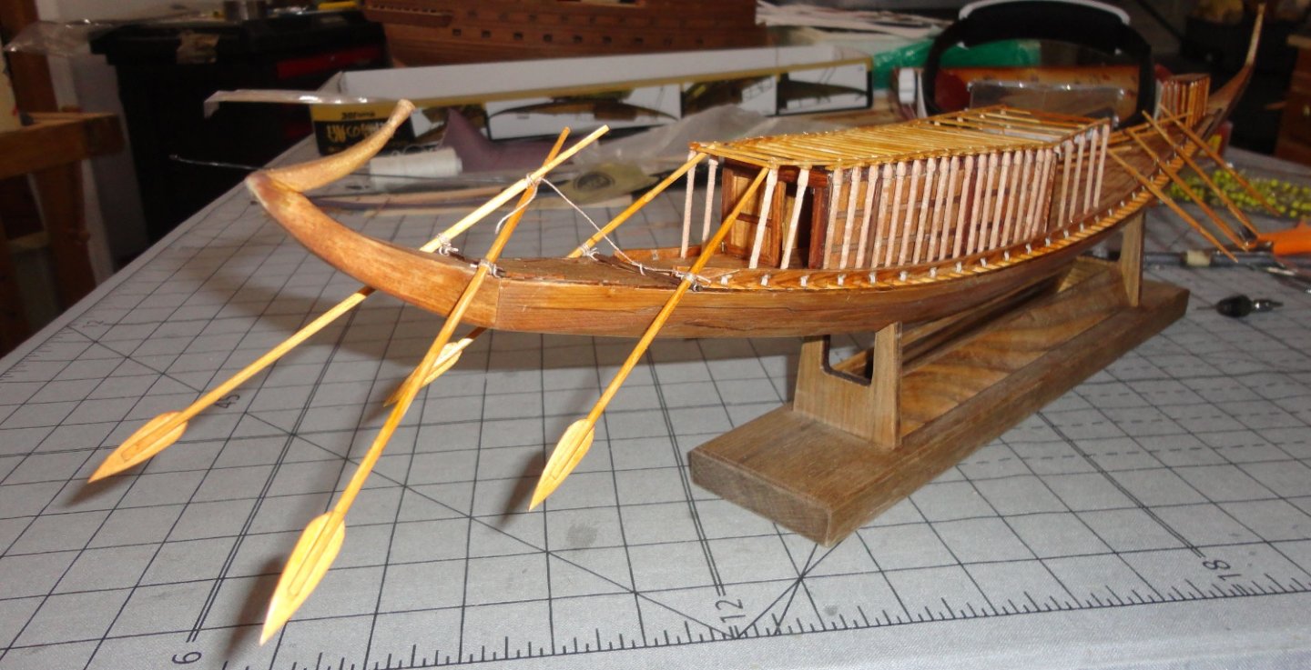
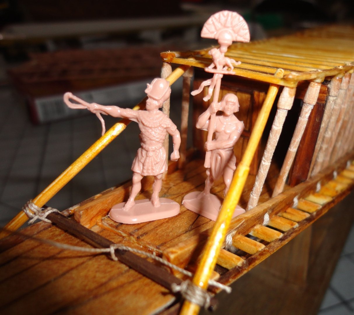
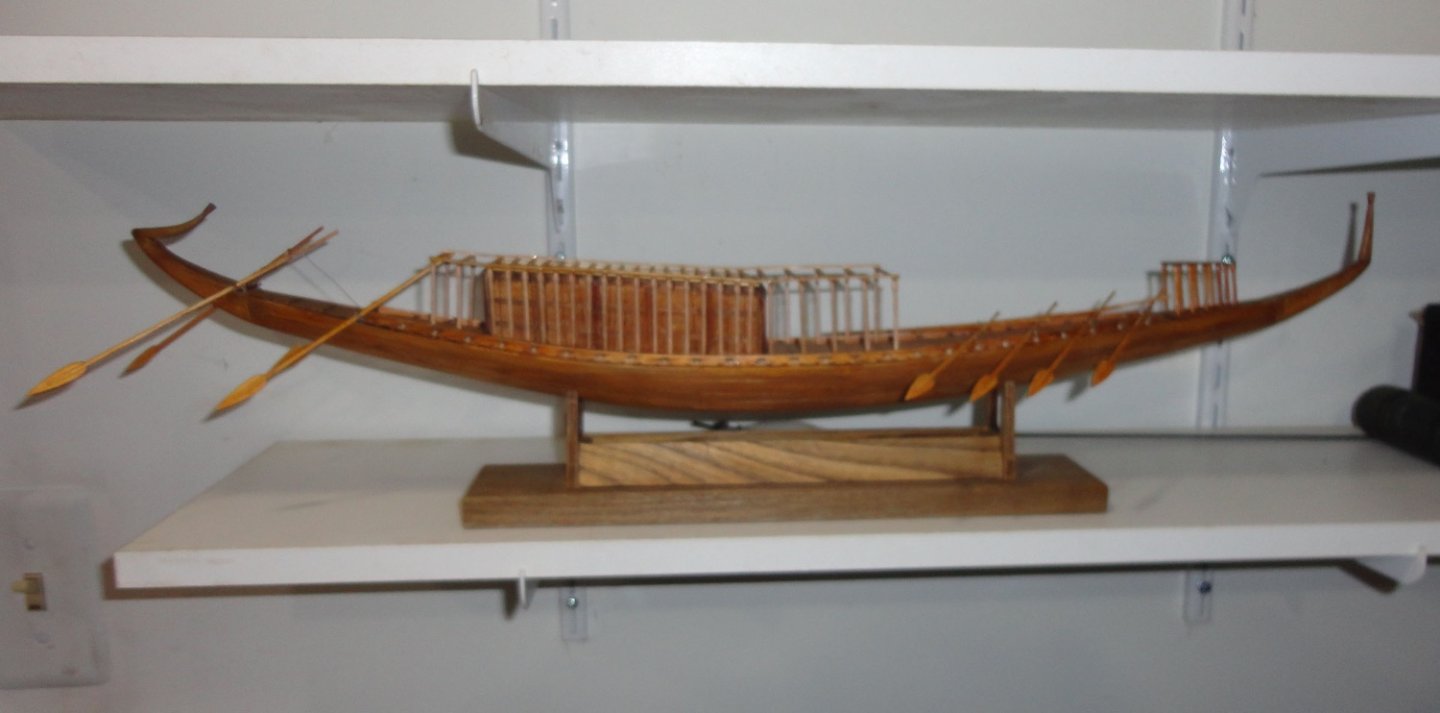
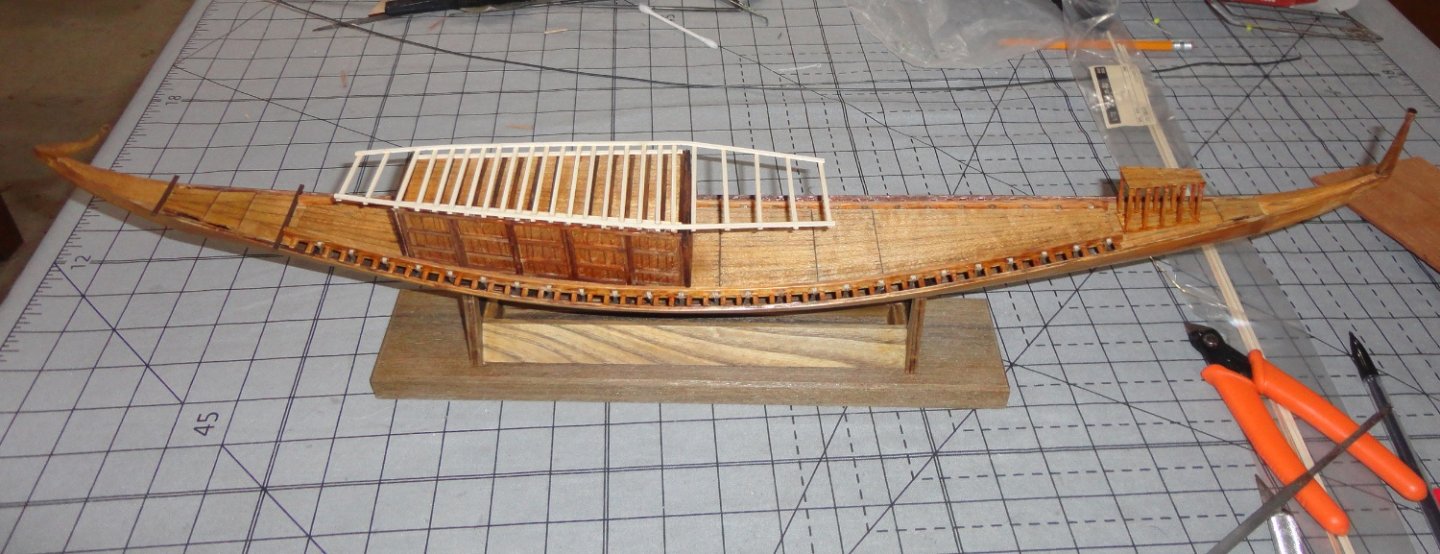
Well, mates ... looks like I've finished the Khufu boat as far as it goes - except for painting a few figures for display purposes. So I'll take you through the final steps. The oar assembly appears straightforward, but still requires care to do right - as does just about everything on this (and every) model. The shot below shows the blade cut-outs that go on lengths of 2mm dowel stock ... and different oar positions have different cut lengths due to the shape of the ship and the increased height above the water near the bow and stern. You can see that the last inch of the oar handle has been turned down (on the Unimat). Otherwise it would have to be abraded in some other manner. Note that the round stock is just a wee bit too wide, so that when put in the slot - the wide ends of the blade spread a little. Don't force this, as the blade stock will split at this point. A flat file was used to carefully remove a little material from opposite sides of the handle stock that will engage the oar blade. Each was trial fitted and adjusted. Since the blades are laser cut, they have flat surfaces along the perimeter. Filing flats on the handle stock provides flat mating surfaces for a good join. Woody Joe got this detail figured right during kit design. Of course, there were a couple (previously mentioned) glitches ... with work arounds. The blades were fitted on the adjusted handles, and I used a dental tool to pick up a tiny amount of CA. By just touching the bit of CA clinging to the tip of the dental tool (one can use a tooth pick) to the joint, the gel CA 'wicked' right into the joint. I'm now sold on the 'gel' form of CA (not the super-thin stuff that gets EVERYWHERE) for fastening all sorts of details. Structural assembly still is done with wood glue. CA sets pretty quick - and I notice hat the gel form has a little more 'open time' (for repositioning, if needed) than the insta-cure thin sort. Then the oar handle is tapered with sandpaper (in this case I'm using a sandpaper covered hacksaw blade as shown earlier in this build), and the oar blade is thinned around the perimeter on both sides. The oars got a thin coat of amber shellac (the semi-clear stuff at the top of an unstirred can of Zinnser shellac, as previously mentioned). The kit instructions said to tie a clove hitch of the supplied thin rope (not too bad, actually - and I used it because it had a 'stiffness' to it that allowed for easier insertion through the tiny gaps in the deck rails) to the oar handles, then tie then to the ship. I decided to 'go' with that, although the original had a somewhat more sophisticated bundling of rope between the deck rail and the oar handle. I favored the 'staggered' rowing oar format, since apparently these oars were manned with standing rowers. A staggered format would keep them from getting in each others way due to the length of oar handle above deck - and resulting longer 'sweep'. I'm showing them in a 'shipped' (or resting) position ... the handles could be extended a bit for active use. The museum in Egypt tied them together in a vertical position ... a likely 'at harbor' position. Oh yes, the LAST thing that I glued was the little forward canopy. It would have been in the way while fixing the oars. Another view. For the stern, I used two steering oar positions with a wider space than on the kit drawing. The museum shows the rearmost position with a pair of steering oars. I put a second set further forward. Perhaps round stock could have been used for mounting these oars on, but it would have to be lashed to the boat. The flat stock use per the kit is simply glued. If my supports were a bit longer (going further out board), the lashing of the steering oars would have been easier. Hopefully, all the hindsights mentioned throughout this build will help other builders who choose to do this project. The sternmost pair were lashed together and tilted by means of the rope. The next pair had the oar handles 'hitched up' so the ends could be swiveled under the end frame of the canopy. A little CA on the lashings will prevent future slippage, and the need to re-adjust the oar angles. I'm very happy how this one turned out, and declare it a FINISHED build. Huzzah! I knew at the start that this was something do-able over the summer (the slow way I work), yet my estimate is that the actual BUILD time was only about 60 hours ... something that could be done in a couple of weeks (with glue or finish drying time allowed) if one had nothing else to do. I find myself best by Admiralty tasks, plus work and teaching assignments ... well, its better to be busy than 'going to seed'. I suppose I'll have to do some more on the Wasa (Vasa is now preferred by the Swedes), but managing all the carvings/decorations plus guns and gun ports is daunting. I've decided to portray it still 'under construction' with only the first sections of masts in place - and minimal rigging. Yup, a slight unsteadiness these days in the hands/fingers make the prospect of extensive rigging a challenge. Below I've put a figure of Pharaoh inspecting his new Solar Ship ... and I might paint-up a few of these figures for fun sometime. I will add a rolled-up cloth to represent an un-deployed canopy cover. Apart from having minimal rigging, this is not a 'tall' ship ... so it fits right on a shelf as shown below. 'Didn't care for the supplied nameplate, so I omitted it. I'd still rate this Woody Joe kit in the beginner category ... but it's really on the 'cusp' of intermediate. As another builder remarked, "Its easy, but not too easy." Now, one can build it without the enhancements I did - specifically, turning palm-head verticals for the canopy supports ... and doing all the lashings of the deck rails to the cross supports for the deck. If one is happy with building "as supplied", the kit will fall in the 'middle' of the beginner level. During the build I discovered how to make my own rope, and any kit requiring rope can benefit from better 'miniature' rope. If you don't want to bother with a mini rope-walk, there are sources to buy superior rope. Why go to all the trouble and time of doing a wood ship model and just used 'fuzzy' rigging thats not much better than heavy sewing thread? Of course some kits provide rigging rope that is better than average, and imperfectly usable. The journey of a hundred miles begins with a single step! Fair sailing, Johny

- 63 replies
-
- 9
-
-
- Finished
- Khufus Solar Boat
- (and 1 more)
-
'Couple of observations ... It is highly recommended to 'fill' the space between the keel and first bulkhead PLUS the the space between the first and second bulkhead (even the 2nd & 3rd at the stern, and in some cases, at the bow) with filler wood - such as basswood (cut to suit 'with the grain', as you don't want to shave end grain). THEN do the fairing. One can see in the pictures that the planking tends to 'straighten out' somewhat between these bulkheads. Many builds show the 'filling' technique ... and some do not - and you can see the difference in results. Filling prevents 'over fairing' on one side of the bulkhead - in your case the 2nd one. Now, you have two planks in place - but its not too late to undo them and utilize filler blocks. BTW - you can let them the blocks 'stick out' some when gluing in place, because you will fair everything once the glue dries. It looks like you are building a double-planked kit, and many with awful-looking first planking resort to slathering on lots of filler and re-fairing (sanding like hell) prior to second planking. But the better the first planking, the less likely that the planks will be sanded too much (even right through!) in the process. Better now to take a step backwards and remedy things. Another observed that the planks (in the affected area) are 'too wide'. Of course they need to be wider amidships, but tapering the ends will help you. Again, there are builds and a couple of tutorials that show helpful techniques - you just have to find them. In the 'old days' many ship model kits had hulls carved from a solid blocks and were finished-faired by the builder ... no planking involved. BUT ... there is no reason one can't build one of those kits and add thin planking to a properly faired hull for a better look on the model. Even ships that were painted (like clippers) can benefit, since some of the grain and joints will 'show through' the paint job.
-
British Pound weakness vs. the dollar
Snug Harbor Johnny replied to Stevinne's topic in Wood ship model kits
Don't forget that decent buys can be 'vintage' kits (of good quality) that are being sold off (EBAY or flea market) ... and even incomplete or partially built kits can be a source of building stock and fittings. -
'Gotta love spell Czech, mate. 'Love the notion that the Glory might have transported canaries ... 😉
- 3,560 replies
-
- 1
-
-
- clipper
- hull model
- (and 2 more)
-
This topic was discussed by Rob Wiederrich (Glory of the Seas build, and others). I've noticed in 19th c. photos of clippers, that deadeye lacing and ratlines all appear black. If they were natural, they'd show up a lot lighter in the black-and-white photos. Yes, I've seen the present H.M.S. Victory useage of 'natural' in these specific applications ... no telling why, but it you look for photos of 20th c. to current rigging on 'tall ships' (and the like) - you'll see the predominance of dark rope ... making what is now on the Victory exceptional. And yes, 'black rope' (as opposed to an application of dark 'oil' or thinned tar) is an expediency in use today that is understandable - and perhaps less flammable. And yes again, if one looks at a lot of recent ship model builds you will find many using light colored rope in the aforementioned areas - and I've seen one with white rope. This seems to be a relatively recent 'fad'. Yet photos of 'old' ship models made over many decades show very dark or black for these items. So the question is (comparing with usage in actual sailing ships), does one want to choose 'natural' rope in the subject applications based on on finding an 'exception' in usage - or does one go with what is seen in the overwhelming majority of cases?
- 43 replies
-
- 1
-
-
- Mayflower
- Model Shipways
- (and 1 more)
-
Note that the lacing between the deadeyes and the ratlines are 'tarred' (blackened ... some insist a dark brown when fresh, but they turn nearly black soon enough) ... as they are considered part of the 'standing rigging' (ergo in place for long periods of time). If very light line is used for these features on a model, they can always be darkened after the fact by carful application of a colorant. Of course, that is non reversible (don't know why one would) except by replacement.
- 43 replies
-
- 1
-
-
- Mayflower
- Model Shipways
- (and 1 more)
-
What's wrong with Artesania Latina Constellation?
Snug Harbor Johnny replied to Antti's topic in Wood ship model kits
Per a Colonial period Naval Historian, John F. Millar, the original Constellation was in sad shape in the early 1850's and from a military standpoint it was not worth refitting ('restoring' ?, not that this term was in use then) ... BUT they wanted to build new ships. Congress was stingy at that time, so the Navy requested money to refurbish the Constellation. That funding proposal got through, so what the Navy did was tear apart (scrap, really) the Constellation and salvage some fittings - then build a new ship using some of the fittings from the original warship to technically 'refit' the original. Yes, indeed, what floats in Baltimore harbor bearing the name Constellation is a Civil War era warship. -
I surmise that they are that way when installed. Yet with constant use, they might 'sag' (stretch) just a little. Wet line stretches more easily under stress (usage). We've often demoed Colonial crafts under a period-looking canvas top (with a ridge pole), held up by wooden verticals at the corners (and ridge) that we secured with rope going out to iron pegs driven into the ground. The guy ropes went under the bent top ends of the metal stakes, then up a distance where I tied (and still do) a taut line hitch (an old boy Scout skill). Everything is adjusted to be square and taut, but on returning for day two of a weekend event - all the lines go slack a little being all wet with dew (this 'droops' the canvas some). So the first job is to pull-up on the taut line hitch so the tentage is again stretched. As the day progresses (unless it is a rainy day) the canvas and lines dry out and are subject to shrinkage. (Yeah, 'shrinkage' ... "I was in the pool ! - remember the Seinfeld show ?) Anyway, this puts a lot of stress on the tentage and can even pull out some of the stakes if I don't go around and let out the excess tension by slipping the taut line hitches a little. This I surmise that ratlines would vary naturally to be anything between straight across and hanging a little slack, depending on the weather and the amount of usage - which on an active ship would be a lot.
-
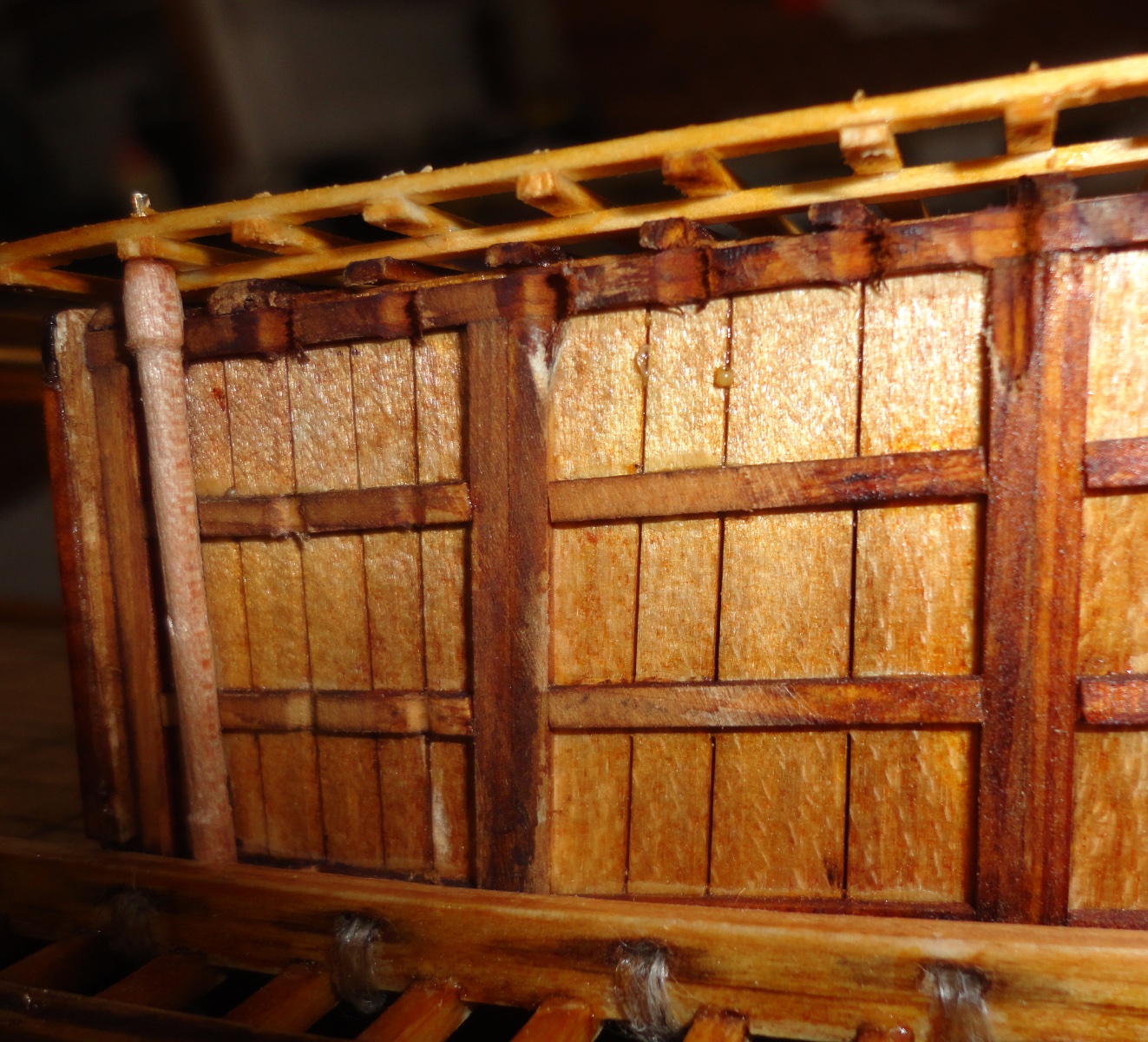
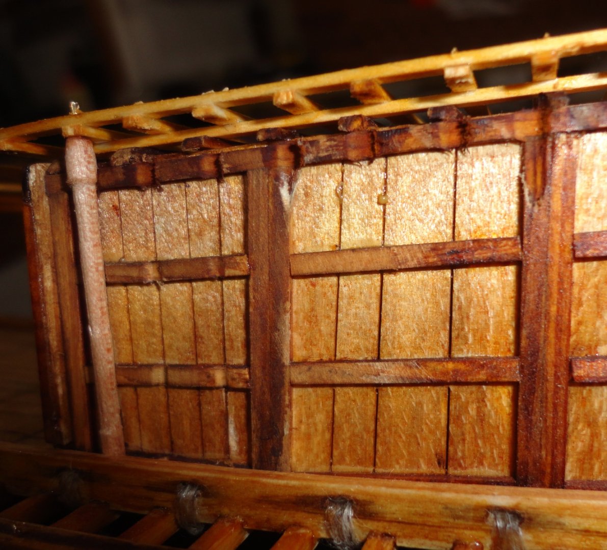
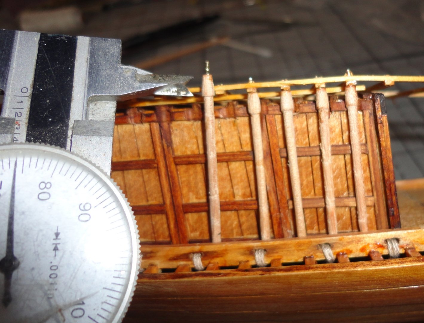
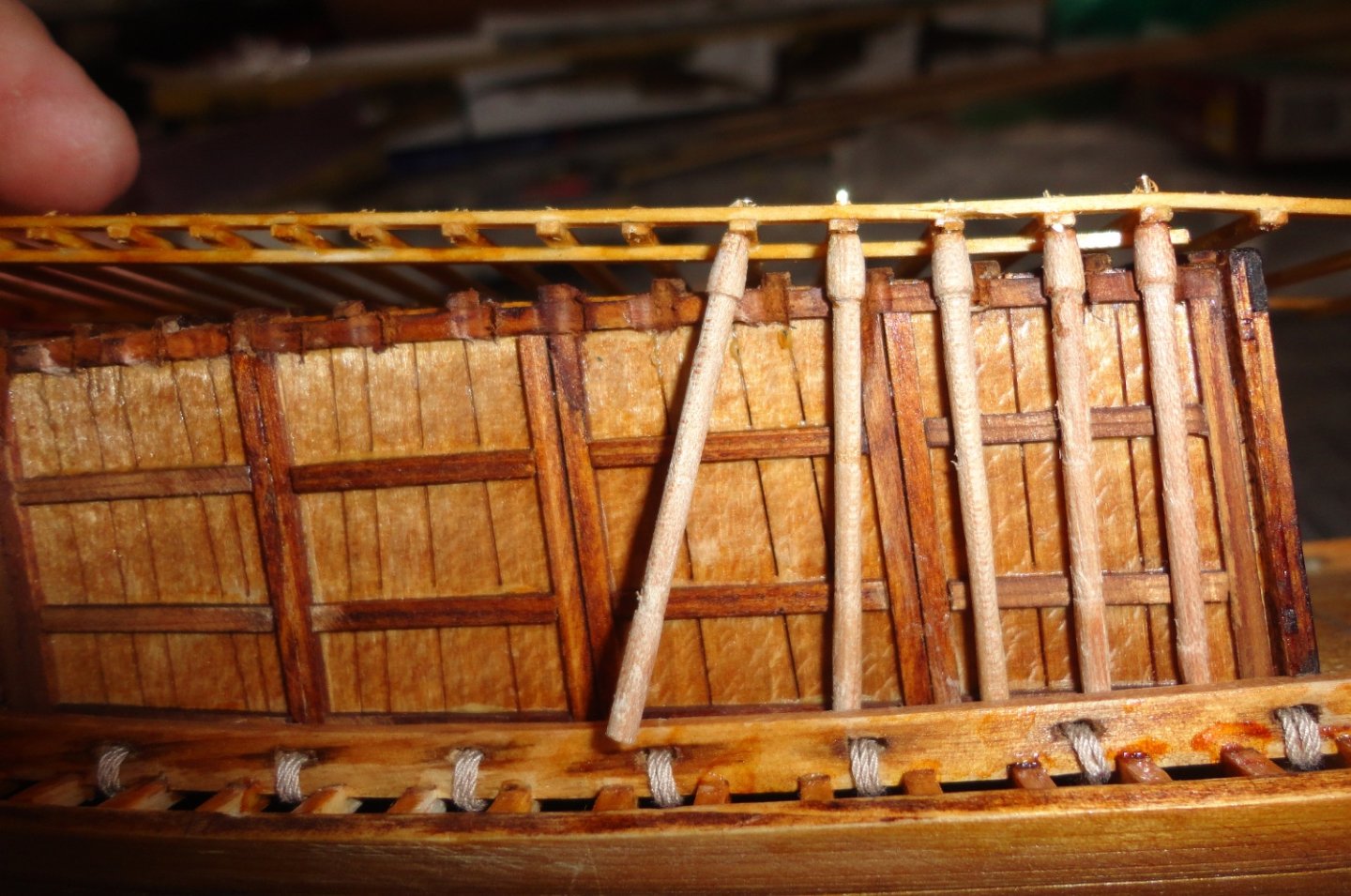
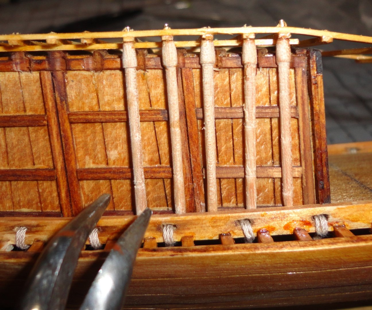
Installing the cabin and cabin took several steps. After a couple trial fits, it was clear that some indents needed to be dremeled along the cabin roof to accommodate the swelled heads of the canopy uprights. As previously noted, these are a bit out of scale, and the space between the cabin walls and the upper deck beams is tight. There seems to be a slight miscalculation somewhere in the kit design, since there is a little more space in that area on the original. It appears that they show the upright resting ON the deck beams (where they are more easily glued) rather than behind. In a do-over (and advice for someone else with the same project) should have me moving the attachment points of the side panels further in on the back of the end panels ... a move would require a little re-engineering of the slots that the side tabs go into. Another route would be to remove a sliver from the center of the end panels (prior to building them with framing wood) - perhaps only 1/8", regluing the panels together, then making the framing wood go out 1/16" further on each side. The cabin top would also have to have 1/16" removed on either side - following the edge contours already laser cut. This would be a great model to scratch build in 1:48 scale ... about 3'long, and planking could be individual strips - the canopy uprights would be closer in scale (the way I made them). 'Enlarging' the plans and kit parts would be a faster track to a larger version. Anyway, after adjusting the cabin, it was glued at the corners using get CA. Now that I'm getting the hang of using this bonding agent, I can see how handy it is for many modeling applications (but by no means all). Then I set and glued the front verticals. In any tight spot, some gel CA can be put on a non-porous surface and the tip of an XActo or dental tool can pick up a little bit to touch to any small area. The gel CA tend to go where it needs to in the 'nooks and crannies'. Then I started working both sides toward the back, first putting the raw vertical (they came out all different lengths) to the cabin and using verniers to gauge how much needed to come off each one (the resultant lengths also vary). That bit was transferred to the vertical and trimmed by rolling a knife over the end. Now each piece is winkled in by lifting the back end of the canopy frame upwards (the thin wood is bendable without snapping), and tilting the base of the vertical enough to get it over the deck rail and moved into position. Some of them needed a slight length adjustment, then were refitted. The excess soft brass jewelry was pliable - so helped in this process, whereas if the wood had been turned into thin spiked ends they would likely have kept breaking. Soooo, it seems doing them the way I did worked out better, and the excess pin material will be flush-cut when complete with ... jewelry (beading, actually) flush cutters. The Admiral turned me on to the many tools one can get originally designed for bead and wire work. One caution ... when flush cutting a small protruding bit, it can 'fly off' at h high speed - so wearing clear plastic eye protection (if you don't wear glasses already) is advisable. Mate, you don't want a wee bit of sharp-edged wire getting into your eye ... and you don't want to start wearing an eyepatch. Arrrrrrrrrr ! Positioning was adjusted with any convenient tool. The wood turned has enough natural color to it (not sure which wood) that I didn't want to darken them with further color ... otherwise they might 'blend in' to the back drop. The top frame was made of a very white cedar, so color was need there. Once again, if the manufacturer used heartwood cedar (and some of the planks had heartwood zones), then only natural (clear) finish would be needed. Cedar can naturally darken over time (just look at photos of the original), and unfinished heartwood (where certain rot-resistant chemicals are) cedar will oxidize better left unfinished so more oxygen can get to it. The 'porch' areas were done from the cabin outward, end everything was tacked well with CA. Now THATS what I'm talking about. Phew, I'm getting into the home stretch. There are only the oars to make and mount, plus perhaps some figures (optional). 'Feeling good now how everything is turning out with this build. I'll have some final analysis when done. Johnny


- 63 replies
-
- 7
-
-
- Finished
- Khufus Solar Boat
- (and 1 more)
-
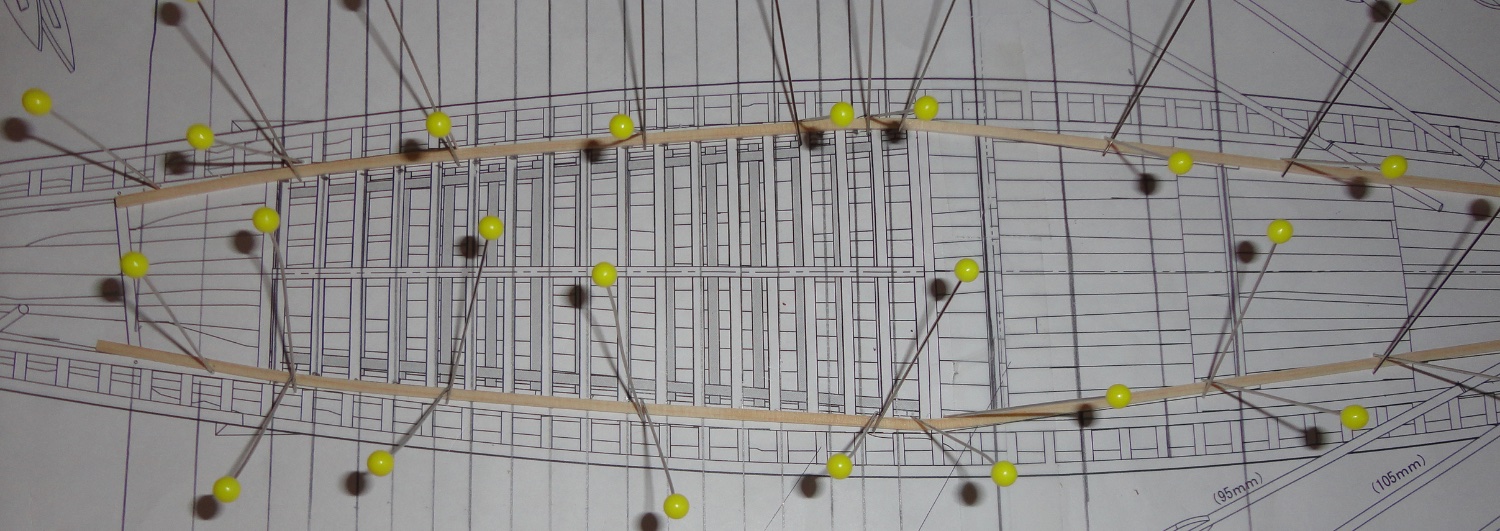
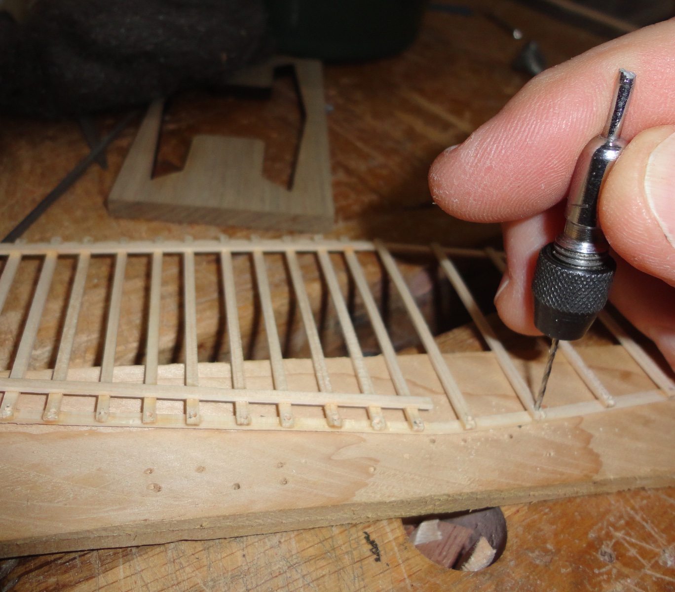
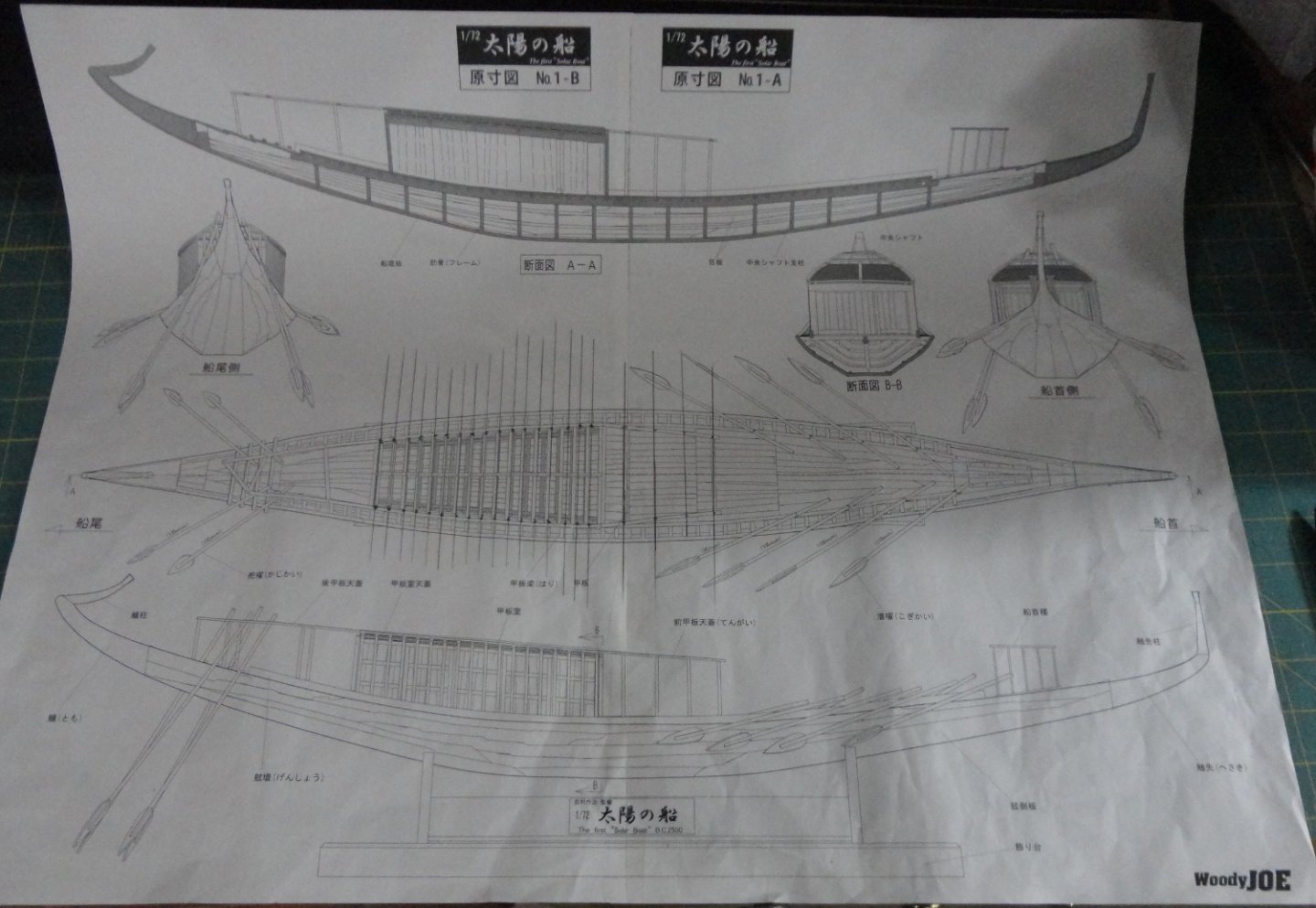
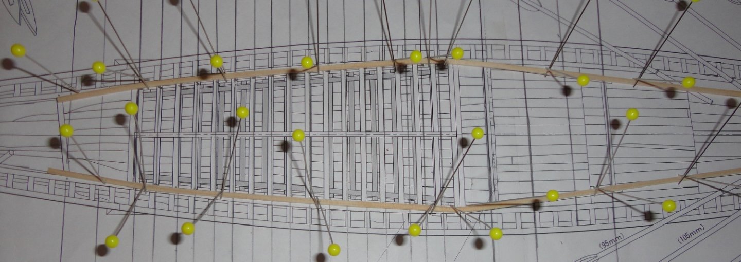
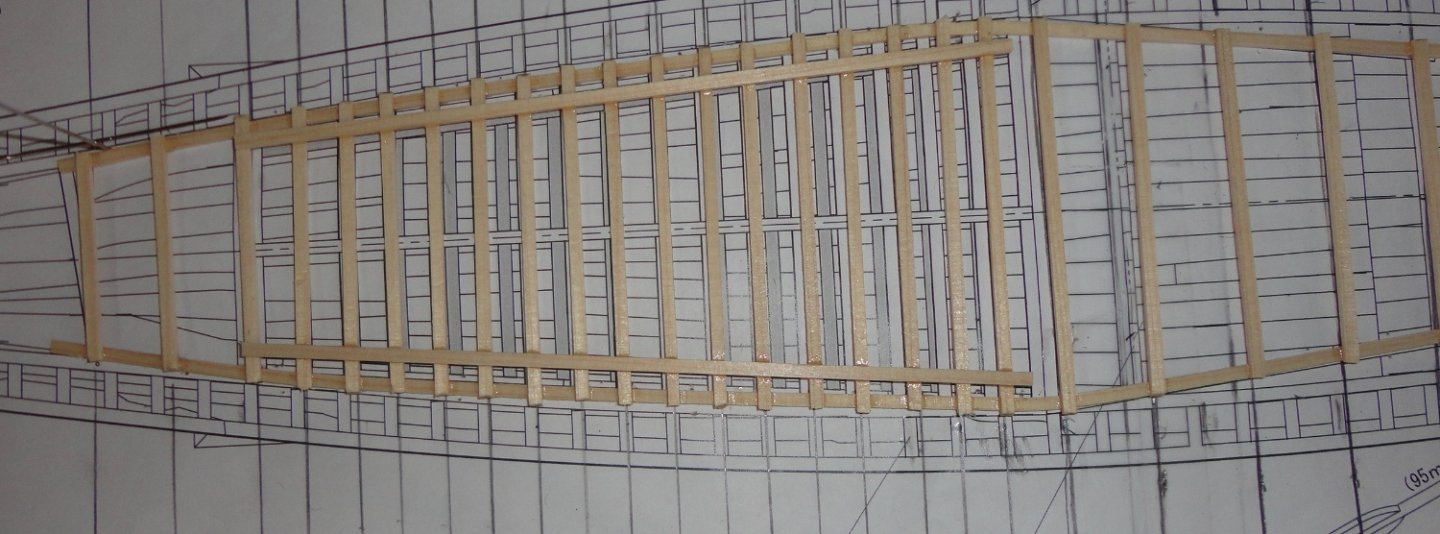
Often I think and re-think how to proceed with something ... a chess game of sorts. What one does can affect other aspects of a project, and 'painting oneself into a corner' is something to be avoided. OK, so after enough prevarication I taped the two-piece plan together - pictured below. The way the main canopy frame has to go together, I decided to build it "upside down". The instructions provided by the manufacturer on how to exactly go about building this feature are ... well ... vague. There are edge stringers on top over cross ties that rest on a pair of thin beams to compensate for the side-to-side curvature of the cabin roof. I put the cabin (upside down) on the plan and marked with a pencil points where the palm-head verticals must go. These were connected with pencil lines to use as a guide when laying down cross pieces. On closer examination, I had to **** some of the dots slightly - and I decided to add some overhang in the back. Below are the top stringers applied first (after bending them - moistening the point of bend first)), and retained with cross pins. I didn't want to pin-thru to avoid pin marks as well as to avoid splitting the wood, which is delicate. A couple of pencil line adjustments were made, then I started gluing cross ties using medium-thickness (gel) CA ... and it is much easier to work with than the thin stuff that wants to go all over the place. I just put a small amount where needed on each end a cross tie. I used the plan to measure each tie - making a small pencil mark where needed and cutting the piece off the stock with an XActo. The CA did take about 15 - 30 seconds to 'kick' - this time varied slightly, but once it grabbed the 'weld' was pretty good. Below, the ties are in place, and I added the support rails on top - putting a small amount of gel CA on each spot where needed. It did have enough 'open' time to apply to all the points and position the rail. The plan shows a central top-stringer that I don't see on the original ship - so it was omitted. The last three cross ties on the left were slightly askew - so I was able to cut the affected joints open, adjust the position and re-CA. The canopy frame came off the paper plan, but a few points stuck due to excess glue getting around a few of the joins. The frame was placed on top of the cabin (now right-side up and nothing glued down yet) for a visual check. It will get shellac as the bow mini-canopy received. Things are shaping-up! I hand-drilled 48 holes by hand, as the placement is important. Note that I put a piece of scrap under the frame while drilling to prevent a bunch of small holes in the top of the workbench . It might otherwise have looked like a piece of old furniture with post-hole beetle holes in it. I used a small file to smooth everything over, then CA'd 20 gauge brass wire into 48 canopy verticals (count 'em). I suppose (in hindsight) that I could have turned the very ends into thin points that would have gone through the canopy frame pieces (like on the original) ... whatever. If I thought putting the mini canopy together was 'fun' (who's having fun?), doing the main canopy ought to be hilarious!


- 63 replies
-
- 2
-
-
- Finished
- Khufus Solar Boat
- (and 1 more)
-
Filling and fairing will help as posted above. Even on double planked kits, the same 'pin hole' question applies. Pre-bending planks (with trial fitting) takes most of resistance out of the wood to be applied. I used 'finger clamping' after mixing a small amount of 'one minute' epoxy as an adhesive ... this was before the advent of CA. Be careful will CA, as it can go everywhere (including fingers) without a micro-tip applicator. Hmmmmm, this JUST got me thinking about a new approach I haven't seen yet. What if one glued extra wood just along the sides (or even just one side) of each bulkhead along the edge - sort of like a ship 'ribs' in contact with the bulkhead - but perhaps twice as thick as the kit supplied bulkhead. This would be easiest to do before assembling the frame, but even so, one could glue successive pieces roughly the shape needed to each bulkhead - and then sand them when fairing. Then, as one planked from the bottom up, there would be a 'ledge' to clamp against so there'd be no need for pins or brads even with slower curing glue.
-
One old boss of mine used to say. 'We don't have problems - we have opportunities." Another old boss said (after doing a work-around on something), "It's good enough for a dog." Wood is a 'natural product' and subject to change over time and seasonal movements. I wouldn't bother trying to get a 'replacement', but forge ahead with a work-around like any modeler will have to do from time to time (or even on a constant basis). The above suggestions all can work so you can take your pick. Now I'll throw in another 'solution' to consider. Since the errant bulkhead has moved to 'where it wants to be', you could cut it in half vertically in the center using an XActo and multiple light cuts so that no material is removed (sawing will do that when it makes a kerf, which would require a bit of veneer to apply to make up for the loss and maintain the width of the notch that engages the keel) ... since that seems to be where the piece has warped. Lay the pieces flat on a piece of waxed paper (on a firm, flat surface) so that whichever side has a small 'gap' faces up - and glue them together again with Titebond (excess glue will fill the tiny gap). Lay another piece of waxed paper on top and then a book or paperweight to keep everything flat. Then once the glue has cured (I'd wait a few hours), then add some thin plywood pieces to both side (plus glue, of course) to make a 'sandwich' which you clamp together overnight. Then you will have a strong bulkhead with correct positioning. Now I like the idea of ALSO adding 'spacer wood' between most (if not all) of the bulkheads before fairing the hull. This will make them all mutually supportive, and the chances of further warpage of any member will be almost eliminated. It will also make fairing the hull (a key step) easier, as fore-and-aft abrasion with water tool you are using tends to move the free ends of unsupported bulkheads back-and-forth. Some use basswood (or even balsa) to fill in the space between the foremost and rearmost bulkheads entirely, since that is where there is the greatest bend when planking. Solid filler between bulkheads there also makes fairing easier and provides a good solid surface for planking against. Heck, I'd be tempted to use filler on the entire hull (except where there must be gun ports -if applicable), but the filler only needs to be on the outer portions of the bulkheads. Hmmmm, 'reminds me of the old days when many ship kits had solid hulls ... but you can plank those too! So don't fret, mate ... maybe you can think of something else on your own. Johnny
-
'Seems to me that a person's library is a representation of their mind containing many data points that went into that unique individual. Once freed from this world, that very library becomes scattered ... with select volumes chosen by family and friends, others sold and yet others may end up in used book stores. A few may find their way into landfills. I thought this as my departed father's library was so distributed ... after the person passes, so does their library (perhaps with the exception of U.S. Presidential libraries - effective mausoleums to past Chiefs).
-
I've got the first (ca. 1970) Billings Wasa ('seems the Swedes now prefer Vasa) thad was designed with a forecastle deck and stern resembling their Norske Love, but in 1:100 scale. Last winter I had to do a lot of 'modifications' to alter what I did years ago to better resemble what we now know the Vasa's configuration. Ah, the joys of single planking - which didn't turn out so bad ... but fairing is a must. I do have a scroll saw (a Dremel cheapie - but it suffices), and it has come in handy. They may have an affordable one at Harbor Freight. I decided to use the old Billings Vikings Skibbe (it was 1:20 scale versus the 1:25 of their Oseberg) for materials, since all those 'fiddly bits' were just printed on sheet stock (and not all that well) - which seemed a little fragile with the passing of years. Instead I've stocked their improved version (at 1:25 now) named Roar Ege. Laser cut kits do have advantages ... if the stock is not too 'singed'.
- 48 replies
-
- 2
-
-
- norske love
- billing boats
- (and 1 more)
-
'Don't use cedar much, and will only cut it outside since I have a 'sensitivity' to cedar dust. Someone I know said that for outdoor use, he recommends some sort of clear preservative to extend the life of the wood. Yet a neighbor's cedar stockade fence has stood there the last 17 years with no attention ever paid to it, and it still look more-or-less OK - although a weathered grey color. Best wishes on your recovery ... AND the new build. BTW, I just love your previously built riverboats! Johnny
- 113 replies
-
- 4
-
-
- Cairo
- BlueJacket Shipcrafters
- (and 1 more)
-
Nice approach on those pins, Tom. I find that my UniMat mini-lathe has come in handy many times over the years, and a three jaw 'universal' chuck comes in handy for working on round stock. A 4-jaw independent chuck handles other shapes. I might try making a form tool ground on the back end of one of my high-speed steel cutting tools to make the 'handle' end of a belaying pin. Not much material would have to come off, then the lower diameter would be a straight cut. Making the profiled ends of canopy supports for my Khufu solar ship build was done sequentially, with the end of the round stock projecting right through the head stock of the lathe and advanced as needed. Individual parts get cut off once formed. Surfing the net for applying leaf to paper has yielded other tips. Sealer is recommended by some before applying size. A good sealer is a light coat of clear shellac (alcohol based) that dries quickly and will be unaffected by either water or oil based sizes. Colored paper has been used to advantage in some applications, although archival paper comes only in white to my knowledge. That could be tinted as desired with water color before sealing with shellac.
- 200 replies
-
- 2
-
-
- Whaling Bark
- Charles W Morgan
- (and 1 more)
-
I clarified my post to make it clear I wasn't cannibal ... something that marooned sailors (or those adrift at sea overlong - like the survivors of the Essex) might be driven to do. 😉
- 63 replies
-
- 3
-

-
- Finished
- Khufus Solar Boat
- (and 1 more)
-
Outstanding method of coppering I haven't seen before ... another reason to go through all sorts of builds on the forum. No need for 'nail marks' since there are tiny surface irregularities in the copper leafing of the paper that 'suggest' nailing - but as you say in 1:96 (a useful scale since I 'round' it to 1:100 when figuring the size to make things, and that makes math easier), you wouldn't clearly see the tiny nails. A full-size copper tack has a flat head, say, 1/4" (0.250"). Divide that by 100 (my 'easy' math) and you'd get .0025" on a model in 1:96 ! Dial verniers show my copy paper to be .004 - .005 thick, so scale 'nails' would be HALF the thickness of a sheet of paper. What, nail heads the thickness of human hair? The only change I can think of to the metal leafed paper method would be to use acid-free archival paper (100% cotton fiber content) as opposed to common wood-pulp paper (acid content varies) that might undergo changes over time (presuming you model will be kept by others long after you're gone - and with the fine job you're doing, this is quite likely) and possibly react with the metal on top. What did you use for belaying pins? brass escutcheon pins? 'Looks like a handy solution since many kit-supplied belaying pins come too short and too 'fat'. I rather like brass touches on a model ... no need to paint or finish since time will slowly put a brown patina over bare brass surfaces. All you need is time. Fair sailing! Johnny
- 200 replies
-
- 3
-

-
-
- Whaling Bark
- Charles W Morgan
- (and 1 more)
-
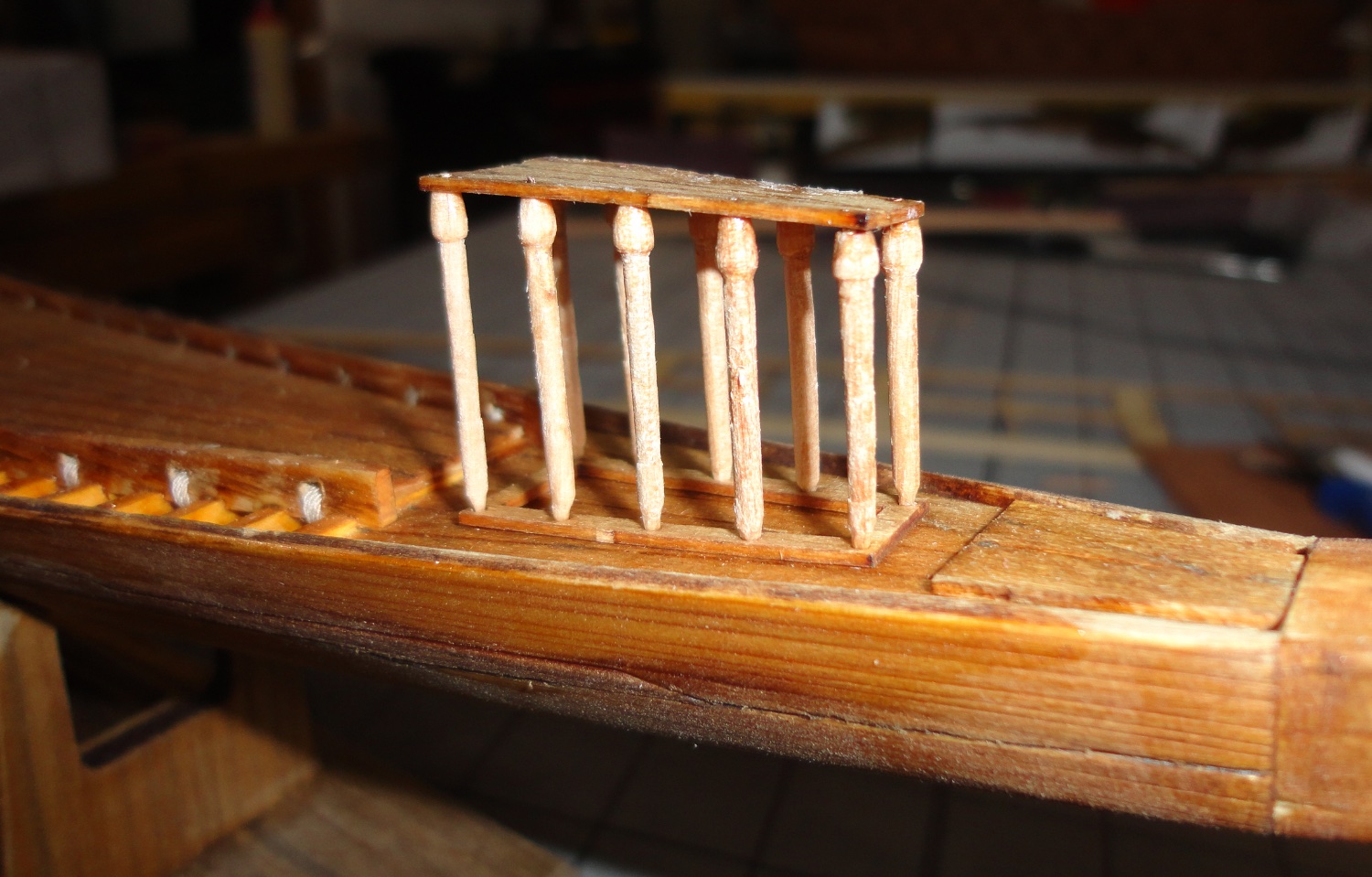
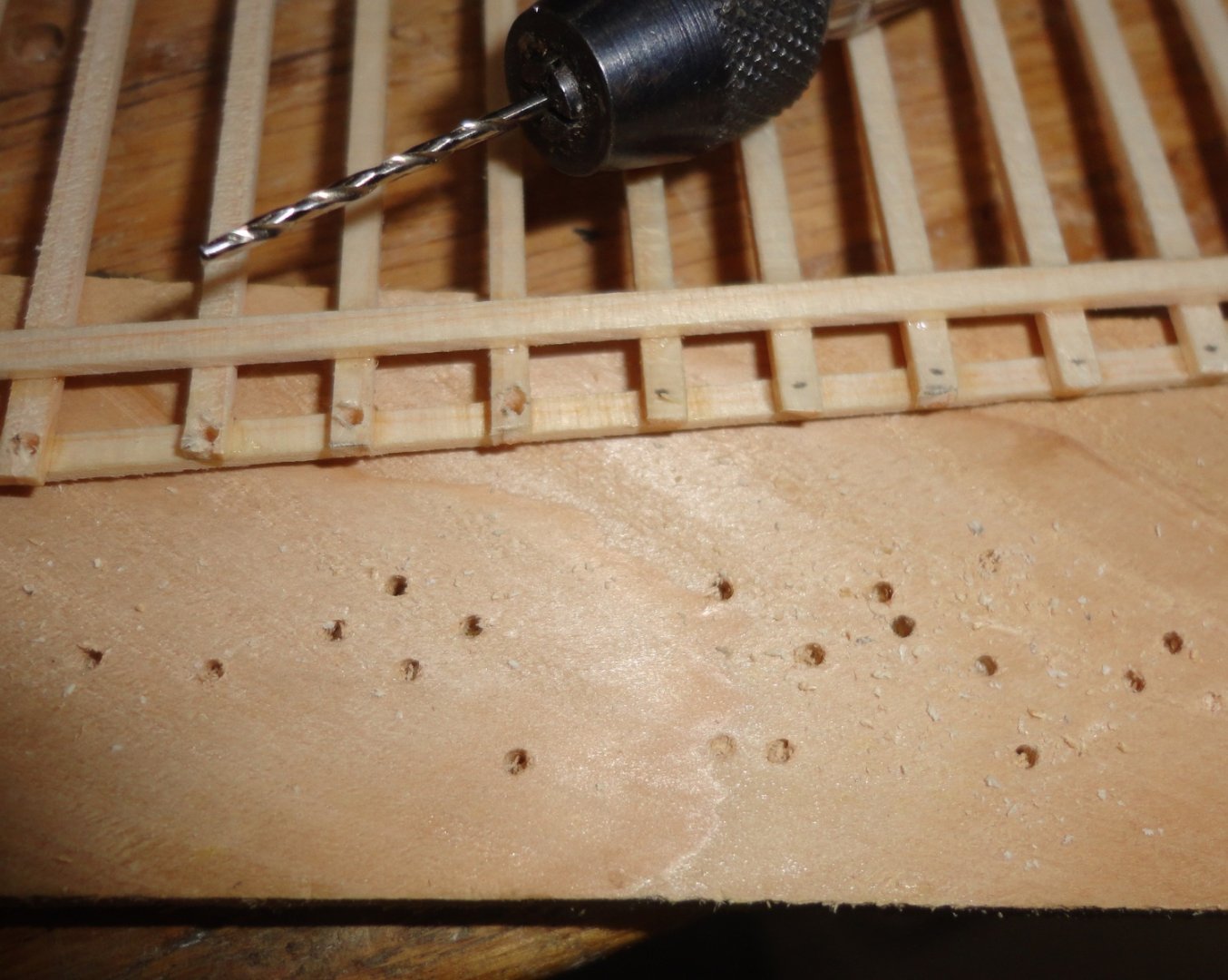
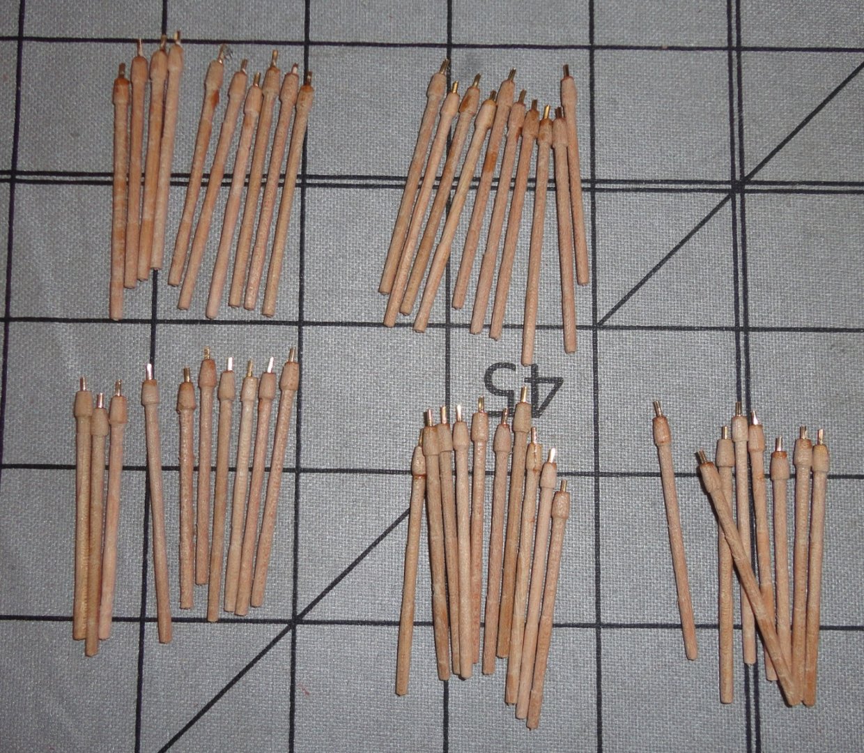
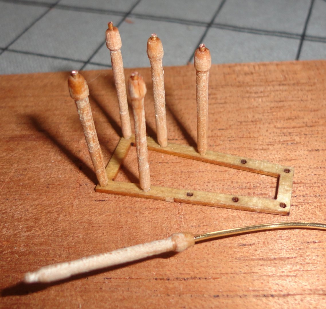
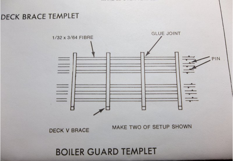
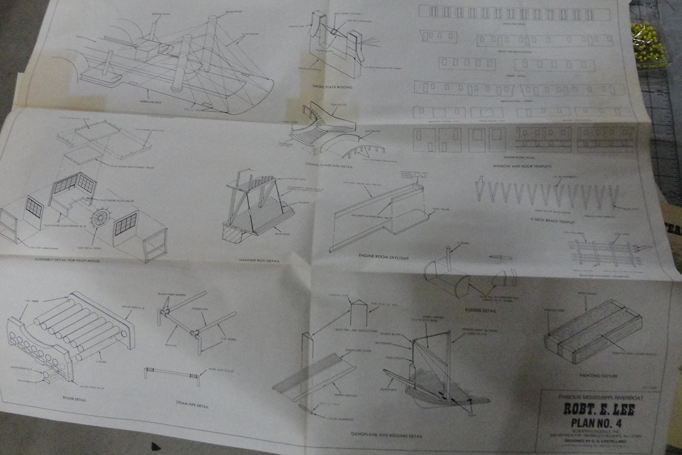
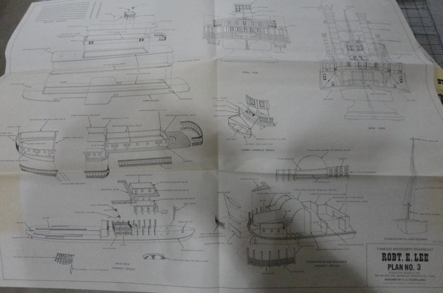
Ahoy ! Its been a busy couple of weeks, and I've been slow turning the palm (not lotus) head verticals ... and pondering how to best make the upper framework. Today I got around to putting the forward canopy together - and it was a lot of trouble ... more than anticipated. The supports had to be cut in pairs to different lengths so the top would be more or less 'level' given that the forward deck is ascending with the graceful curve of the vessel. I put brass wire into the pre-drilled hole in the head of each support, then secured with 'penetrating' CA. The top piece proved to be very fragile - so when I nearly broke it completely, gel 'gap filling' CA was used to get a pretty good repair. As mentioned elsewhere, I find CA wicked to work with and can't seem to avoid getting some on my fingers. So I chew it off (the crusty CA ... not the finger itself !), spit out the bits (not recommended to eat) and touch up any rough spots with fine sandpaper. Too much of this might temporarily remove fingerprints ... something a safe cracker might want to do, but not me. Once each wire set, flush cutters left enough at the tops to engage the wooden canopy roof. Perhaps I should have left extra to help in the assembly - then made a final cut flush with the roof. The photo below shows how I set-up the verticals. The bottom of the verticals were whittled carefully so they would fit into the laser cut post holes. There is stock in the kit (very thin indeed) that one is instructed to 'round' and use for these verticals - but I wanted something a.) more substantial and b.) having the profile at the top. After many attempts because things kept falling apart and getting mixed up, I finally succeeded in getting the thing positioned to accept CA at the top joints. Then the bottoms were glued. The shot below shows the forward canopy trial positioned on the boat. I still will add some shellac finish on the canopy assembly. I realize that a miniature lathe is something a 'beginner' is unlikely to have ... but if one is going to get involved in kit building (or other types of craft work), I highly recommend one. It occurred to me after the fact that I could have a.) chosen a wire drill to match the 20 ga. wire on hand, b.) used the drill butt as an end support then c.) turned a somewhat thinner diameter to the vertical ... but not too much. One can also use toothpick stock with pointed ends to go into the laser cut holes (not unlike the original pictured earlier in this log), The profile head could be a piece of wider dowel drilled out to the diameter of the toothpick and cut off into a little ring that can be glued on to the end of the toothpick. 'Just thinking about alternate ways of doing these bits. In this hobby, one can imagine all sorts of alternative ways to go to tackle any sticking point in the assembly. The verticals are a little out of scale with-wise, but they 'read' very well at an observing distance - and I'm satisfied with this bit. With th3 Ca cured, it is very sturdy and resists finger pressure. Making the main canopy frame is going to be another challenge. A detail from the Scientific Robt. E. Lee steamboat kit instructions gives me an idea of how to proceed with the skeleton canopy top. We'll see. I do have enough verticals, but will make a few spares. Once again - there's no rush in finishing this build, since I want to 'get it right'.

- 63 replies
-
- 5
-
-
- Finished
- Khufus Solar Boat
- (and 1 more)
-
1:162 Robert E. Lee Steamboat - Scientific
Snug Harbor Johnny replied to Snug Harbor Johnny's topic in REVIEWS: Model kits
Ghosh, Eric ... I must first finish the Khufu barge. That ... and the Admiral has ordered solid hardwood flooring to be installed in the parlor and dining rooms! Admittedly, there was assistance unloading and transporting eighteen 70 lb. cartons of oak up into the house, but from here on mate - I'm on my own. Time to re-deck ! Johnny -
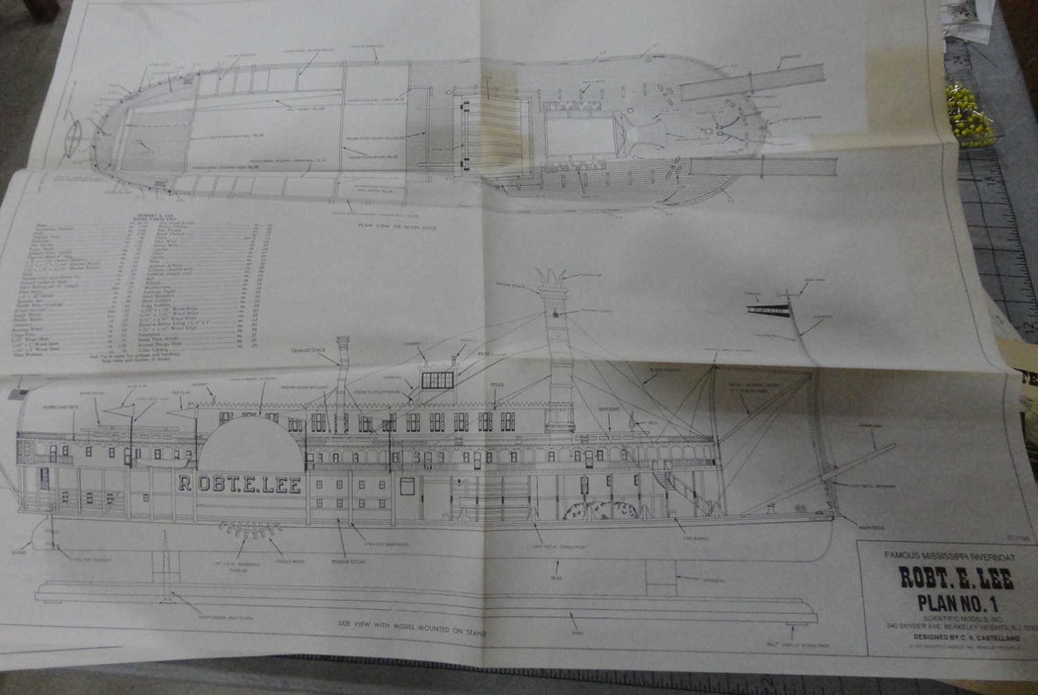
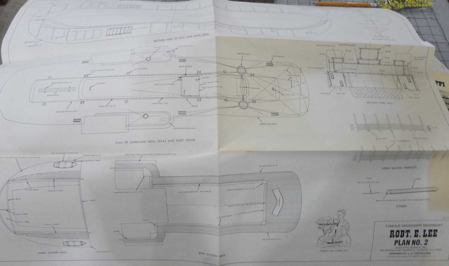
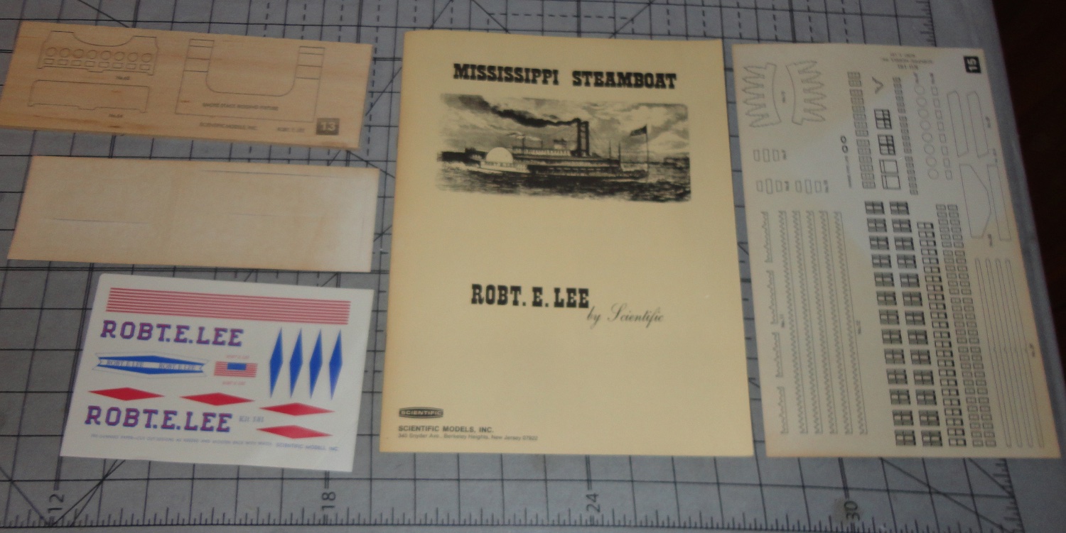
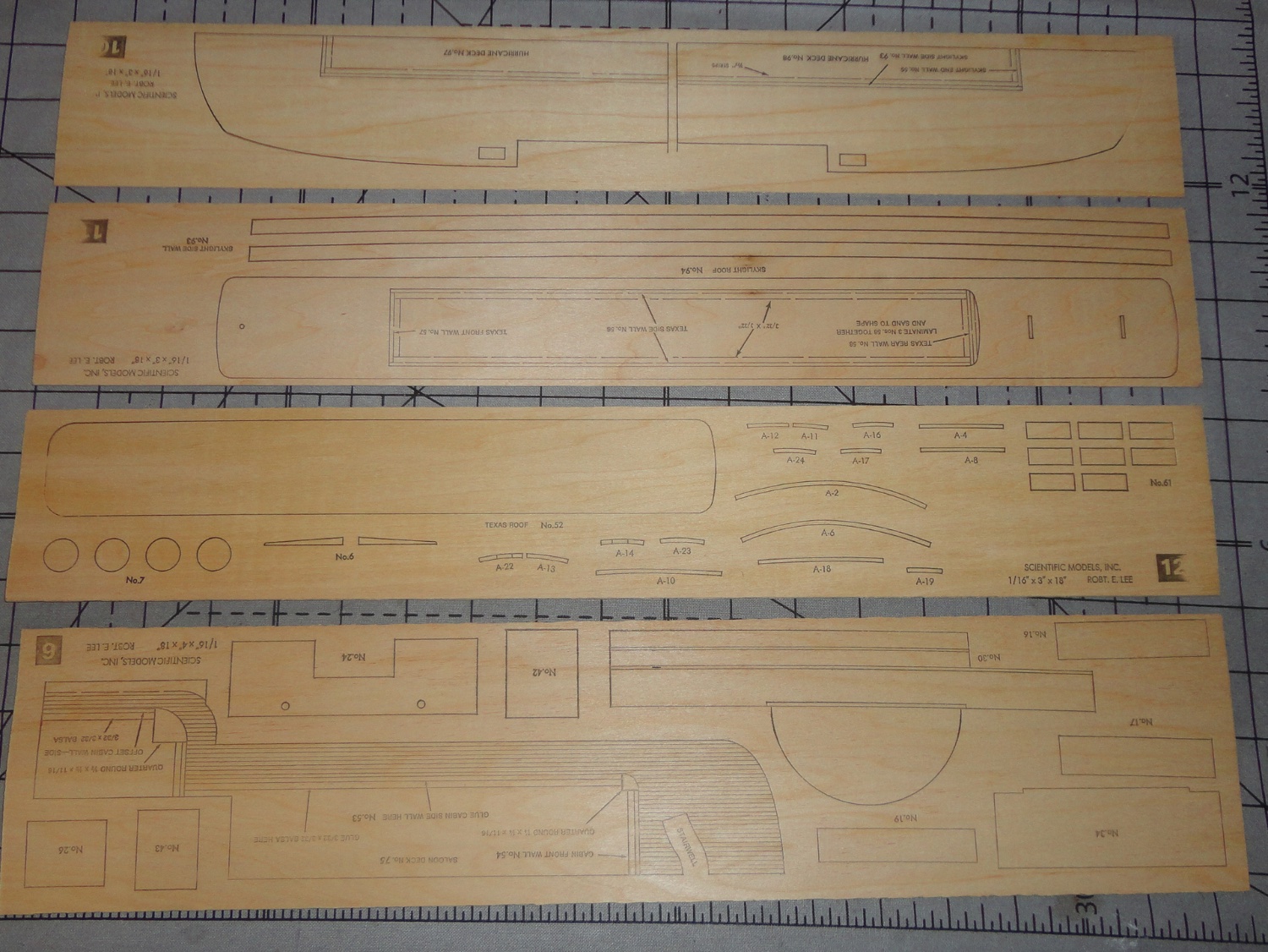
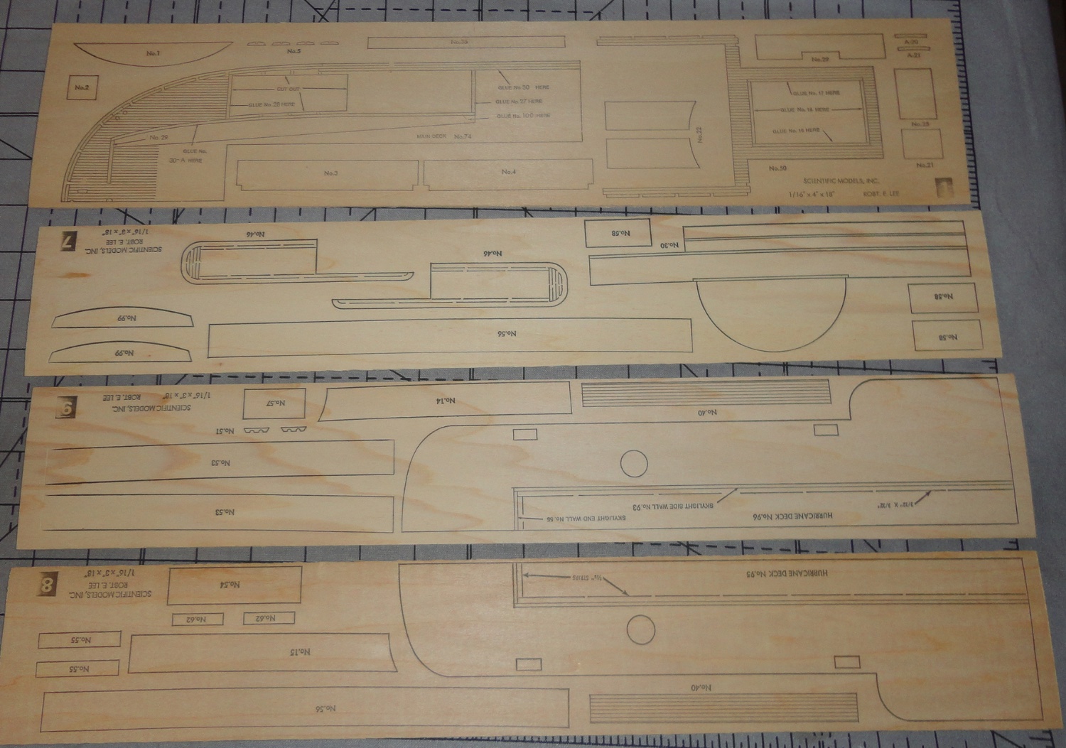
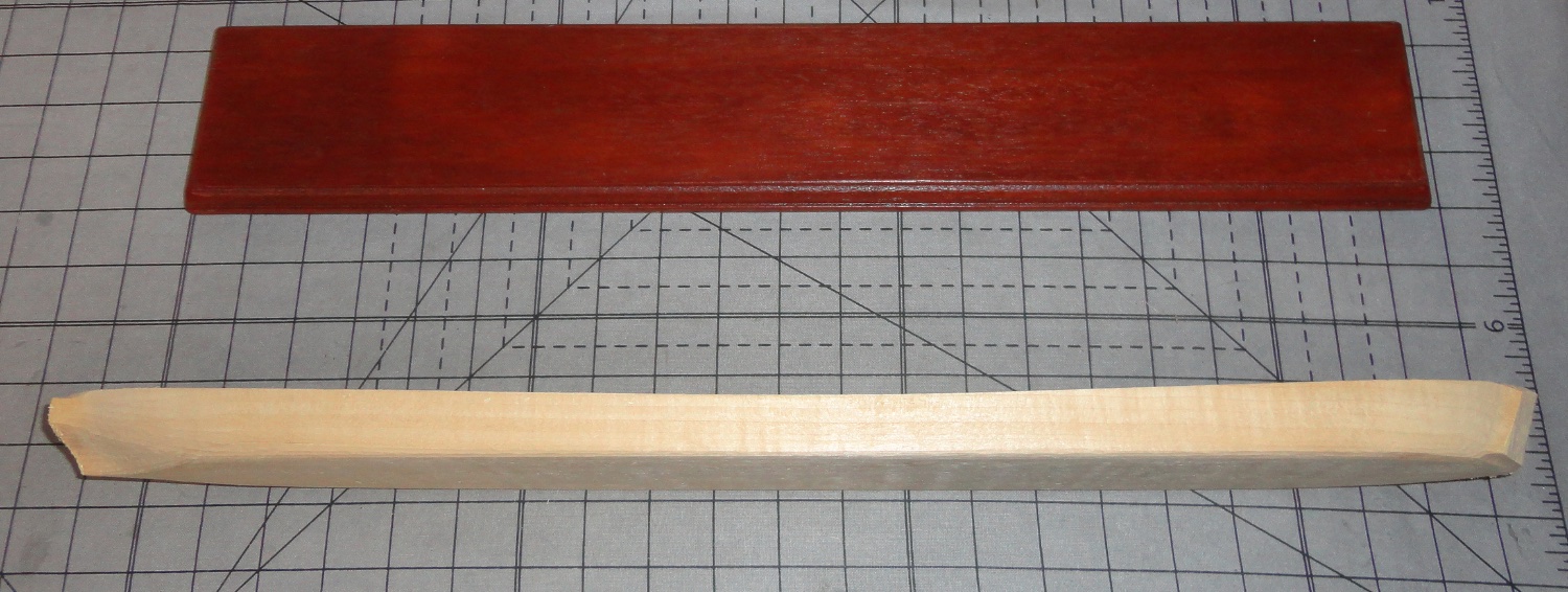
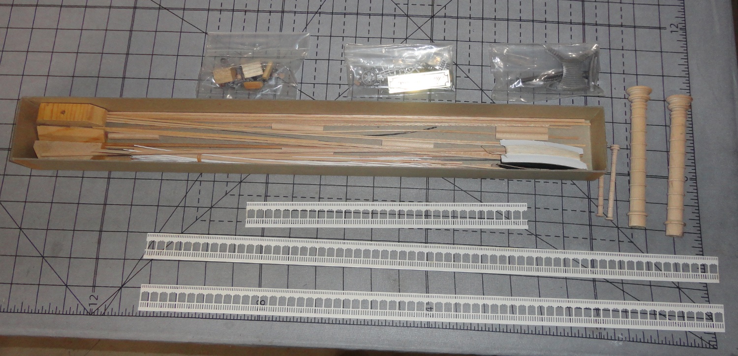
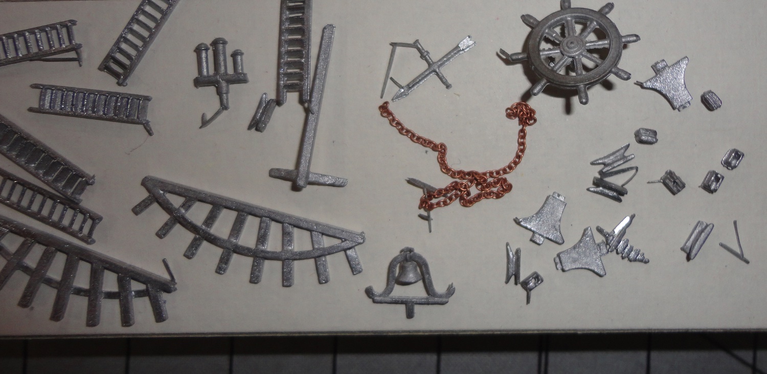
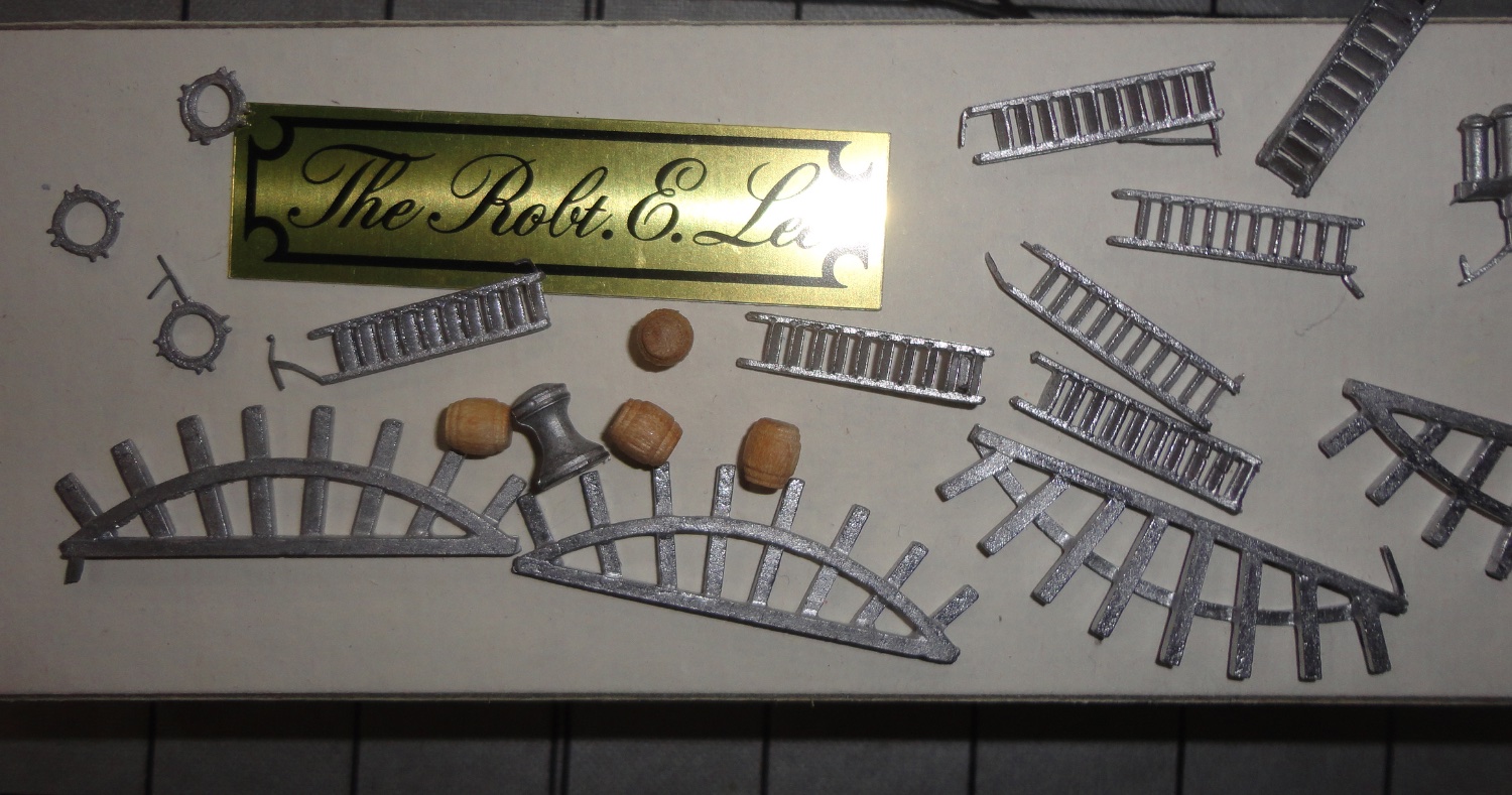
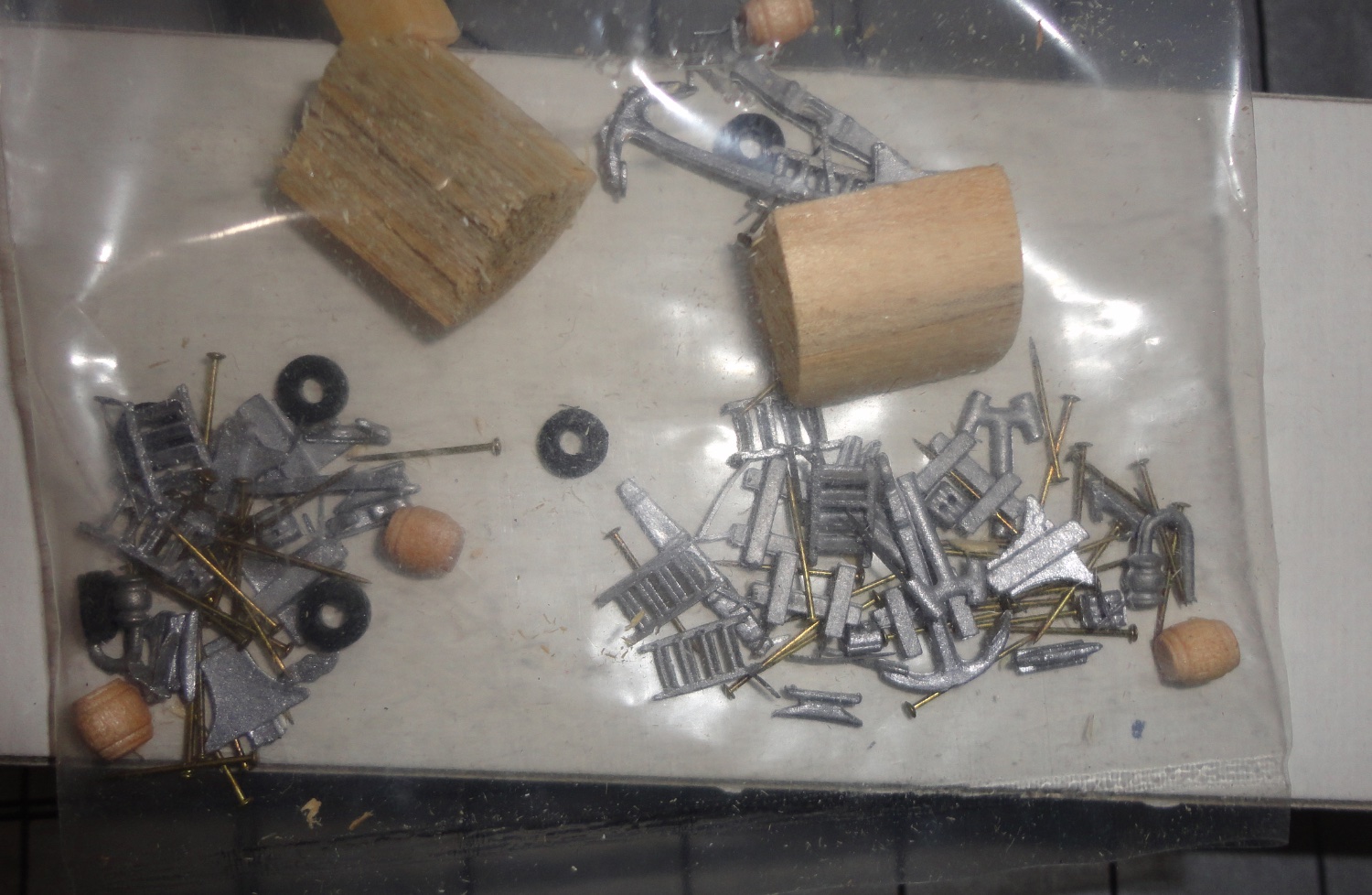
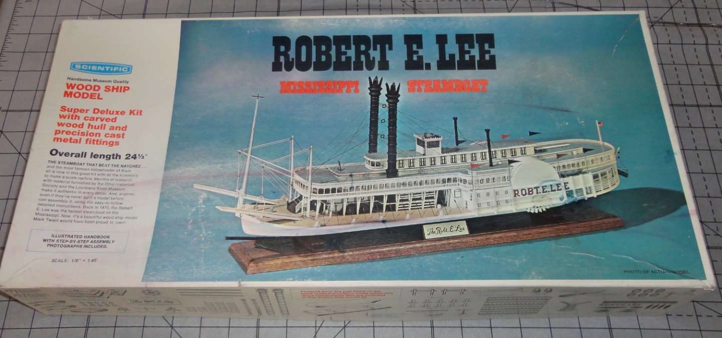
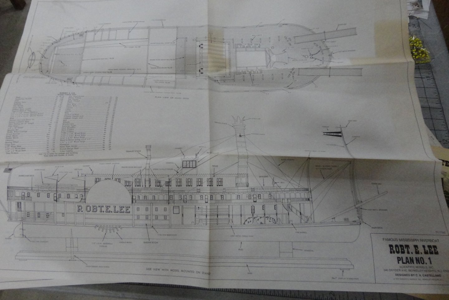
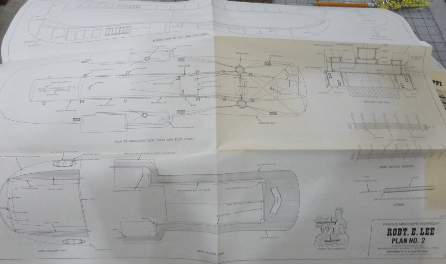
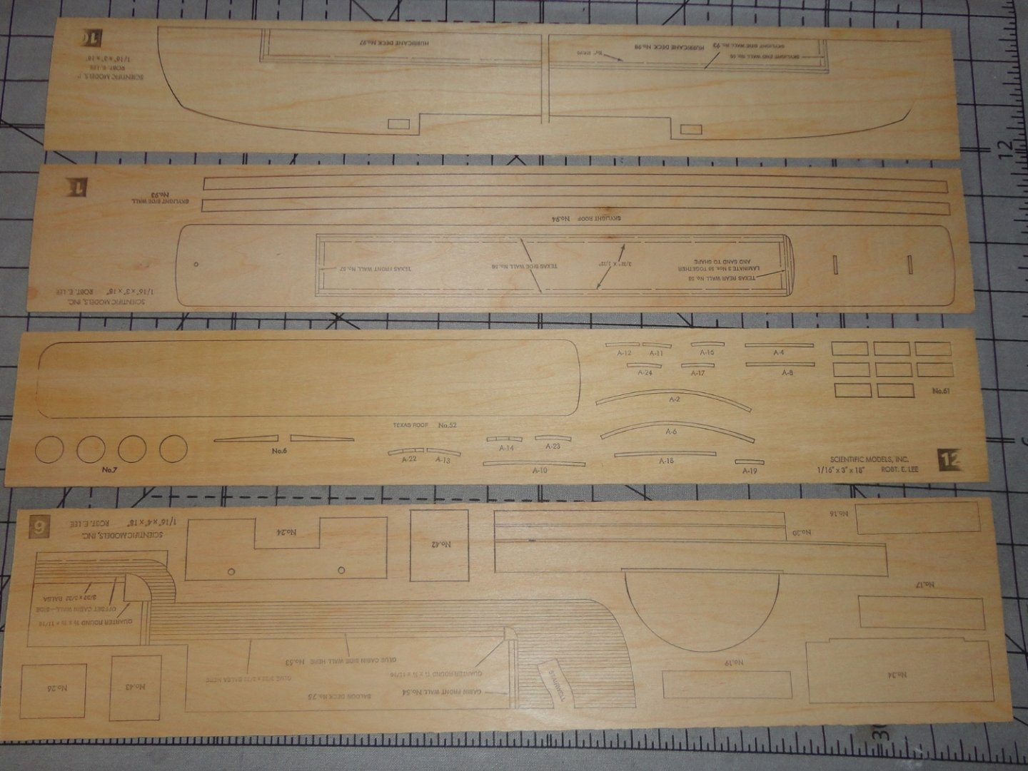
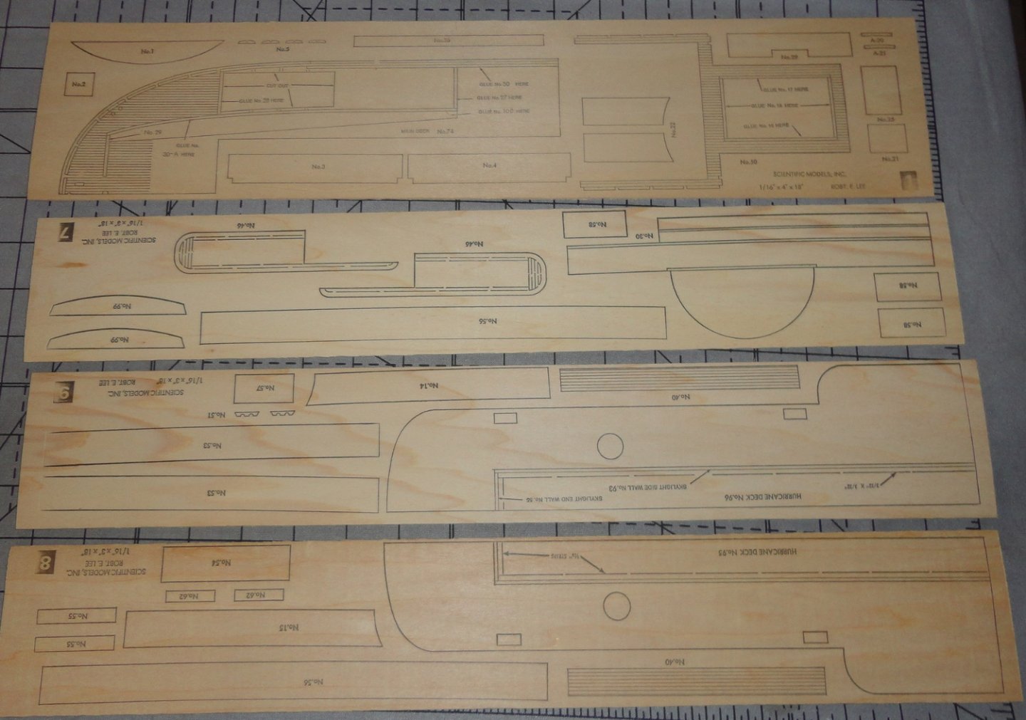
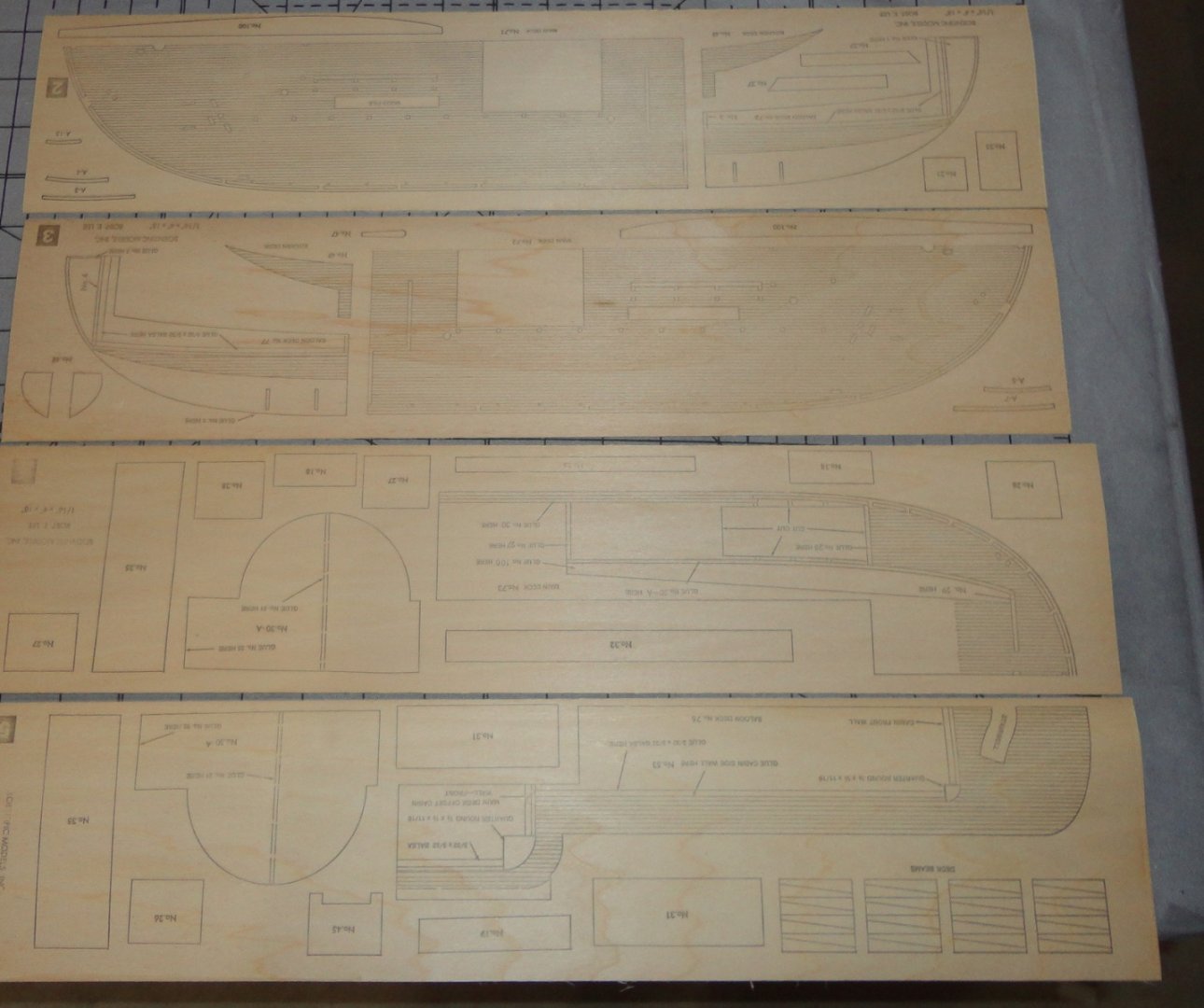
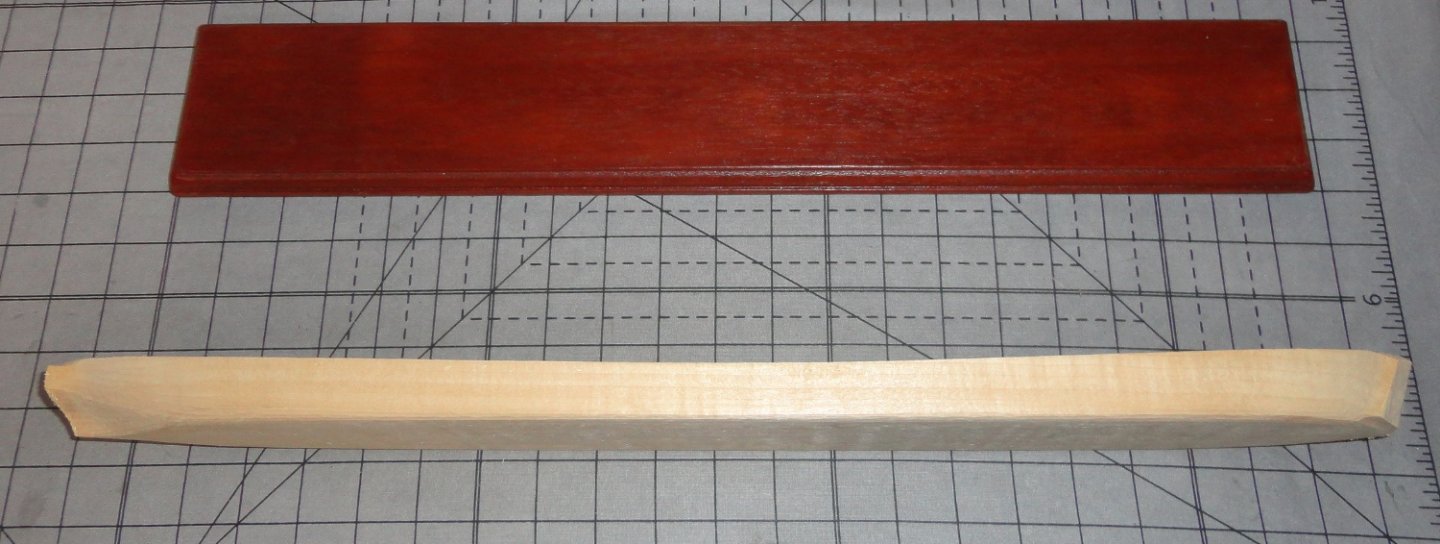
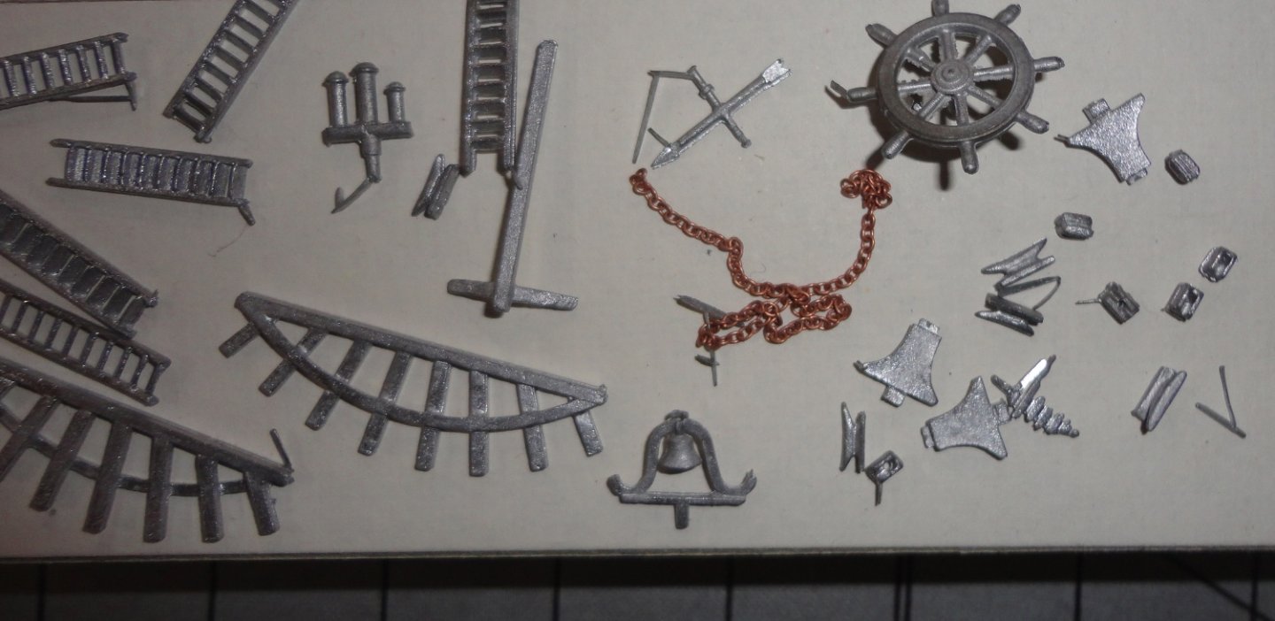
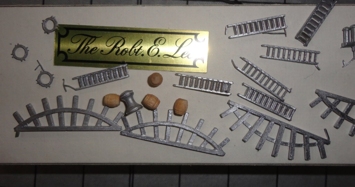
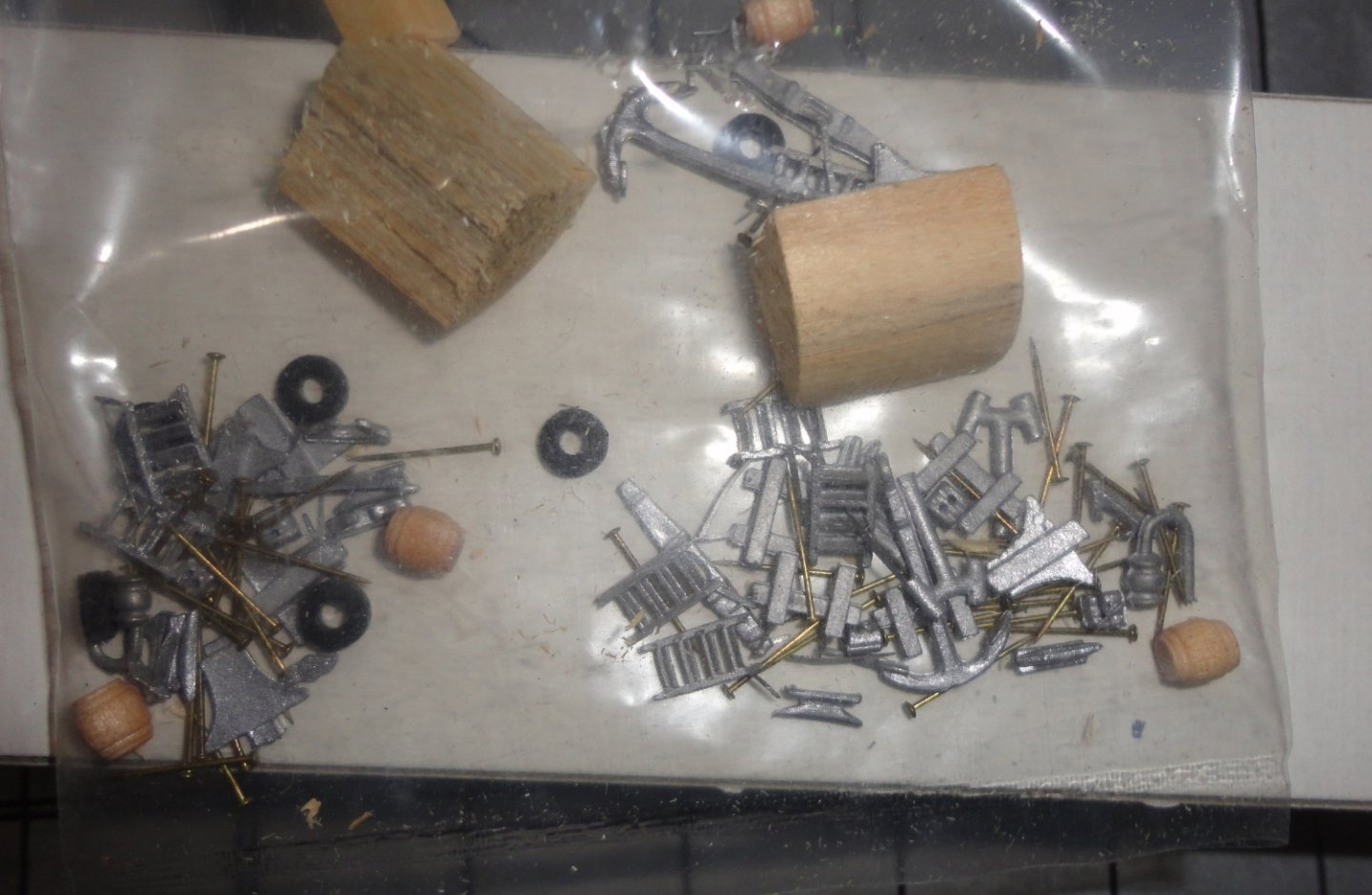
Ahoy ! After following two recent builds of the Robert E. Lee Mississippi steamboat (1866 - 1876 for the first incarnation) I looked to see what options for unbuilt kits might be on Ebay. (Sometimes 'stashes' become available and perfectly good kits get put on-line - which makes a sale more likely than an ordinary yard sale ... and the price can be much lower than new stock. 'Vintage kits' can go for even less.) I couldn't resist the 'buy now' button for the 1970s version by Scientific (made a Cutty back then either by Scientific or Sterling ... can't remember - and a cousin did a good job of wrecking that model for me) for just under $60. Seriously, how much a gamble was that? The prices for the same unbuilt kit ranged in the $70 - $90 range for the most part, with the highest price being $138. So I went for the $60 kit. There were a few forum comments criticizing some aspects of this kit (when aren't there any?) and one characterized it as simplified. Well it just arrived and I decided to my own kit review before doing anything with it. The 'real' scale of this kit works out to 1:162 based on the 21" wooden hull size of the model and the 285' hull size of the original. (The Pyro/Lindbergh plastic kit hull is ALSO 21" - so components from the plastic kit can be used to ease/improve the build of the Scientific kit ... there's noting like a real wood model hull.) A misunderstanding (printer goof?) of the Scientific kit put 1/8" = 1.45' on the box. First up is the box art, which should be familiar. So here's what's in the box ... and was surprised to see how much was in there, neatly compartmentalized with a long narrow sub-box and spacer. There are two large plan sheets printed on both sides ... something not seen too much in contemporary kits. 'Sorry that the sheet order got mixed. I just LOVE those nice, big plan sheets - chock full of details. And the next picture shows an amply illustrated instruction manual ... another thing you don't see as much these days. All in English (Hey, I got tired of having to use the Google translator on my Tracphone), its hard to go wrong. Now to the right of the booklet is a piece of card stock (something that's critiqued elsewhere) for the windows and some of the trim. OK, for a builder less inclined to model all the windows, I think that this is a valid way to assemble 'out of the box' 'as supplied'. But as another suggested, just get it printed on acetate at Staples. Then small cut-outs can be made on the cabin sides, thin stock can surround the opening to frame the window (slightly covering the cut-out to create a ledge), then the acetate window can be mounted from the back side ... and you have a more detailed window. No big deal. Where another kit might have photo etch for other trim (actually, photo etch can be kinda thin and hard to work with - perhaps better suited to 20th c. kits of battleships and the like), copying that trim on regular copy paper and rubber cementing it onto brass sheet then sawing out by hand can provide an alternative to card stock ... take your pick. BTW there IS a piece of printed acetate (not shown here) included for the windows in the wheelhouse. On the left is the only piece of balsa in the kit - part for making the ends of the boiler and a piece to make a jig to help make three smoke stack spacers (one of the 'fiddly bits' to this model). The color sheet is gummed on the back for application. There area several basswood sheet with printed parts that the builder must cut out. (Another ding from someone who is too used to laser cut parts). OK, but the basswood is not too hard to cut, and a 'rough cut' with space around the printing can be made - then an X-Acto can shave up to the line ... big deal. I mean, are we in a big rush to do our builds? I note that the deck has the plank printed, so one doe NOT have to plank the decks. But then again, if one really wants to - there is nothing to stop one from planking over the deck with the printed lines as a guide. Again, its your pick. The next photo shows a whole bunch of stock in the long sub-box ... too much to try and spread out in this review - but they seem to have included lots to do a fair job on this build. One can, with a little thought, plank over some of the surfaces that are otherwise plain wood if built 'out of the box' ... and that might require a little thin veneer not included in the kit. Again, I don't think its a big deal. Note what appears to be complex gallery railing with 'gingerbread'. This is made of a flexible substrate (not sure exactly what) and painted white on one side. This will DEFINITELY save a ton of work assembling all those pickets. There is stock that gets glued on the surface to make it more 3-D. I rather like this feature of the kit. Note also the fully turned smokestacks and steam stacks. How nice is that? Now there is a basswood hull that only needs some shaping ... nothing too dramatic. A keel piece can be fitted to the bow if desired. Due to the overhang of the deck, most of the hull isn't that visible anyway. I suppose you can plank over it if desired ... another 'bust' that's a user option. I note that the display stand is out of Mahogany (with a finish applied, no less) ... now THAT is something you don't see much these days ! Not shown are 4 felt disks to go on the bottom of the mahogany base ... they seem to have thought of everything. Geeze, have I got my $60 worth so far? But wait, There's MORE ! There are many cast fittings included that see pretty good to me, and can really help because one doesn't need to model them at this scale. The parts seem pretty good as-cast, and can clean-up easily. Part of one of the bags is shown below, with the rest from that bag to follow. The tiny ladders will save a lot of trouble. Cleats, blocks, bell, whistle and weather vane ... the segments of the paddle wheels will suffice, as that's all that will be visible on the model. The next picture was made through the bag, so I wouldn't risk loosing any of the small parts contained therein. OH, and then there is a casting for the 'Grand Staircase' (instructions show how to add the side pieces for the stairs) plus three small boats. Two screws for the display stand are included. I'm no expert by any means, mates, but this kit seems to have a lot going for it ... with work-arounds for any perceived shortcomings. After all, this isn't a plastic kit - seriously, we're supposed to be modelers after all. I've mentioned elsewhere that this is also one of the projects that doesn't involve a lot of complex rigging (stropping tons of block and deadeyes, rigging halyards, lifts, braces, bunt lines, clew and sheet lines ... to name a few). So my review is a definite 'thumbs up', and the relatively modest cost of acquisition is icing on the cake ! Smooth sailing ! Johnny One Edit I forgot to make: The Scientific kit does omit a feature that educated observers will note, and that is the omission of three masts on each side with anti-hogging cable fore-and-aft - presumably due to the amount of heavy cargo often piled on the 'apron'-like deck on the front half of the vessel. 'Guess that was to simplify what is already a sophisticated build. Not to worry, these can't be too much trouble to add. 'Haven't had the opportunity to examine any of the other vintage kits of this manufacturer, and I imagine each will have its strong and weak points. Building a riverboat is like assembling a floating building - an architectural exercise. It is a different beast than 'main stream' sailing ships, and I look at the challenge of a tea clipper or a man-of-war as more of an art form - hence a difference in skill sets and level of difficulty. As an old manufacturing engineer, I'm more 'assembly oriented', and have to work on the artistic aspect versus the industrial.


-
A Happy Day, U.S.S. Arizona BB-39 by Trumpeter Completed
Snug Harbor Johnny replied to Tigerdvr's topic in Plastic model kits
Bravo! Very nice indeed. Now I saw a picture of her early in her career when she had two fire control 'towers' that were a steel 'basketweave' ... presumably so hostile shots could pass right through. 'Don't know of any models made of that version.