
Gregory
-
Posts
3,079 -
Joined
-
Last visited
Content Type
Profiles
Forums
Gallery
Events
Posts posted by Gregory
-
-
-
To get a better feel for the tapering some measurements help.
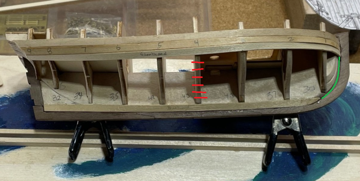
Determine the number of full width planks at '4' then divide the measurement indicated in green by the number of planks. You might also want to do the same at the stern.
However the measurement at the stern might be a little bigger than '4 ' which would require wider stock or the introduction of a stealer.
With a first planking I would leave some gaps and fill them in with scrap.
It's really not that critical for the first planking, but it makes for good practice looking ahead to the final planking.
I really did not do a proper job on my earlier builds, so they would not serve as a good example.
I plan on trying to get it right this time but I haven't caught up with you as far as planking is concerned.
Hopefully I will have something soon.
-
-
29 minutes ago, clarkt said:
Are such services available?
I'm sure they are, but with the same caveats Chuck mentioned. Even more-so if you don't provide ready to go .svg or other vector based files.
Metal cutting would probably add another cost factor over wood.
An alternative, possibly cheaper, would be photo etching.
Just Google " Photo etching services " ...
-
-
-
Tabletop laser cutters are getting cheaper and better all the time.
If I were going to upgrade anytime soon, I would go with this:
xTool S1 Enclosed Diode Laser Cutter
Your main concern would be venting.
-
-
Be sure to bring up questions before gluing or cutting. I have built Gretel before - a couple of times actually.
I have built for family members who just had to have one of those wooden ships they know I spend so much time on.
It's such a quick little build, if you stick with it. I've made a lot of side trips that keep me from forging ahead.
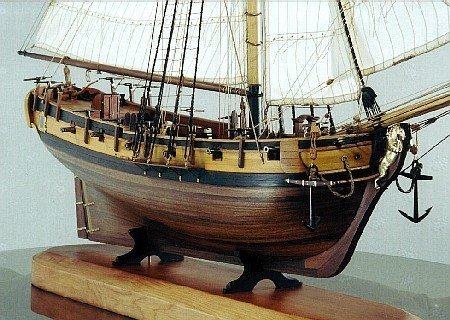
I like to experiment with decorative touches since it was supposed to be a 'Pleasure' yacht.
Here is a shot from my Gretel in the gallery.
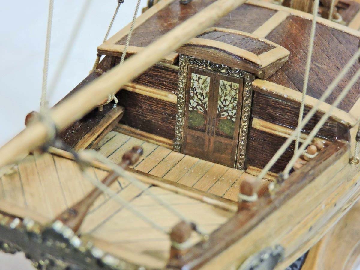
I played with making patterns with the wood on the cabin roof and quarter deck. The cabin doors were printed.
The rigging leaves a lot to be desired because I didn't pay attention to scale very well. The belaying pins can use refinement, and I didn't show proper coils at belaying points.
I built this kit before I had joined MSW and the expertise to be found here.
- Knocklouder, Nirvana and jpalmer1970
-
 3
3
-
-
Here is a link.
You can click through three more drawings.
-
Maciek,
Allan seems to have some historical info regarding gun tackle that none of the kit makers have, or they choose to ignore it. So, 99% of the builds you see here will have the double/single configuration you have used.
Many of the highly credentialed Anatomy of the Ship authors also go with the double/single rig without regard to gun size.
You have a very nice model, and your gun tackle looks really good.
-
I think we have a few AL Bounty logs, so you shoud be in good company.
The high resolution admiralty droughts are available at Wiki. I'll see if I can get you a link if someone doesn't beat me to it...
- Intasiabox, Canute and mtaylor
-
3
-
I was referencing Lavery from " The Arming and Fitting ..etc. " .. He shows a lot of drawings and no mention of bricks after the introduction of iron stoves.
Not the final word I'm sure, so perhaps someone has further references.
- No Idea, Keith Black and mtaylor
-
3
-
What ship?
Once iron stoves came into general use around 1757, the hearth was made of iron.
- mtaylor, No Idea, Keith Black and 1 other
-
4
-
4 hours ago, Intasiabox said:
The kit is 20+ years old.
Have you been able to inspect the kit?
A few years ago, ModelExpo unloaded a lot of AL Bountys at a very low price because a lot of the wood was moldy. Might be a good reason to avoid it if mold is present.
Otherwise, because of the reasons Jaager mentions, old, dry wood is not necessarily a problem.
- mtaylor, Intasiabox and Canute
-
3
-
Thanks for that.. I was trying to figure out how to do that but wasn't aware of the free form selection..
I did manage to get the work done with Photo Shop Elements..
- thibaultron, mtaylor and gsdpic
-
3
-
-
If you can PM me a copy of the image, I can do it for you later today..
Gregory
- thibaultron, JKC27 and druxey
-
3
-
This won't help now but I think your problem is the overlap.
I realize you were trying to model actual practice, but I don't think the overlap would be visible at scale.
You may have to resign yourself to living with the results of the raised edges..
-
-
Glad to be of help.
I have neglected my Gretel build, but hope to get back to it soon.
I look forward to seeing your progress.
-
Don't worry about sanding the first planking too thin at the deadwood.. Just allow for the 2nd planking to fit flush with the keel and stern post.
I have built a couple of these kits; one of the older original Mamoli kits, and one of the newer Dusek versions, which I believe you have.
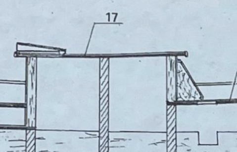
In the new Dusek kit, I found part 17 to not be a good fit, being too small. Too big would have been easy to correct. You may need to make a new part.
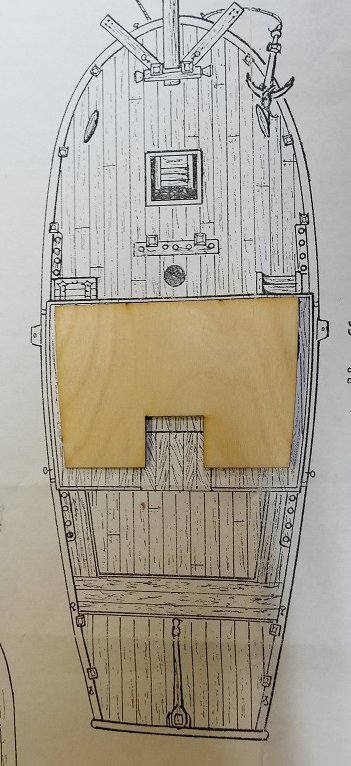
This is how the supplied part fit on the plans.
I found a couple of layers of card stock to be adequate for making a replacement.
- Bryan Woods, jpalmer1970 and Nirvana
-
2
-
 1
1
-
_RMG_D3970_2.jpg)
Angle Drill
in Modeling tools and Workshop Equipment
Posted
Why not just a right angle punch of some sort? All you really need is just a hole/ depression that you can stick something into to represent a treenail..
It seems to me that the work you have to do after you have a hole will be more of a challenge than the hole itself.