
Gregory
-
Posts
2,735 -
Joined
-
Last visited
Content Type
Profiles
Forums
Gallery
Events
Posts posted by Gregory
-
-
You might try some Fiebing's leather dye.
I have used their Burgundy for a reddish look on some boxwood blocks. It can be lightened by wiping quickly after application, with alcohol..
-
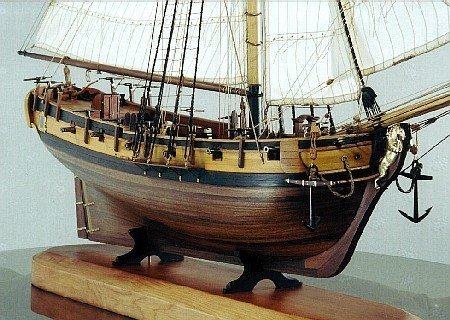
According to the book " The Low Black Schooner " by John Rousmaniere, she was launched with copper..
-
I believe she was coppered.
-
-
Another small update.
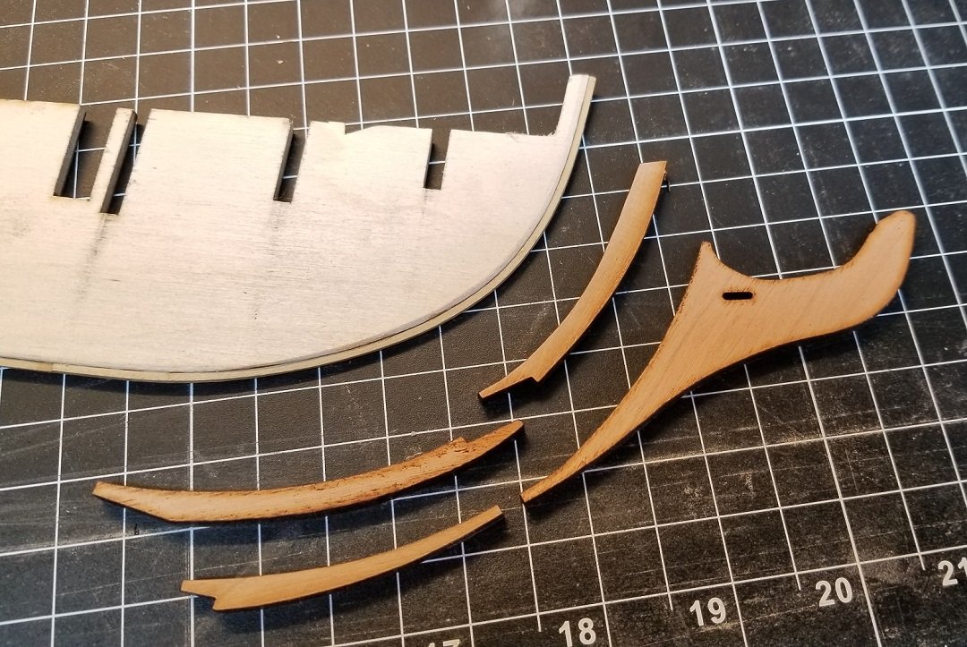
I cut the stem pieces out of cherry.
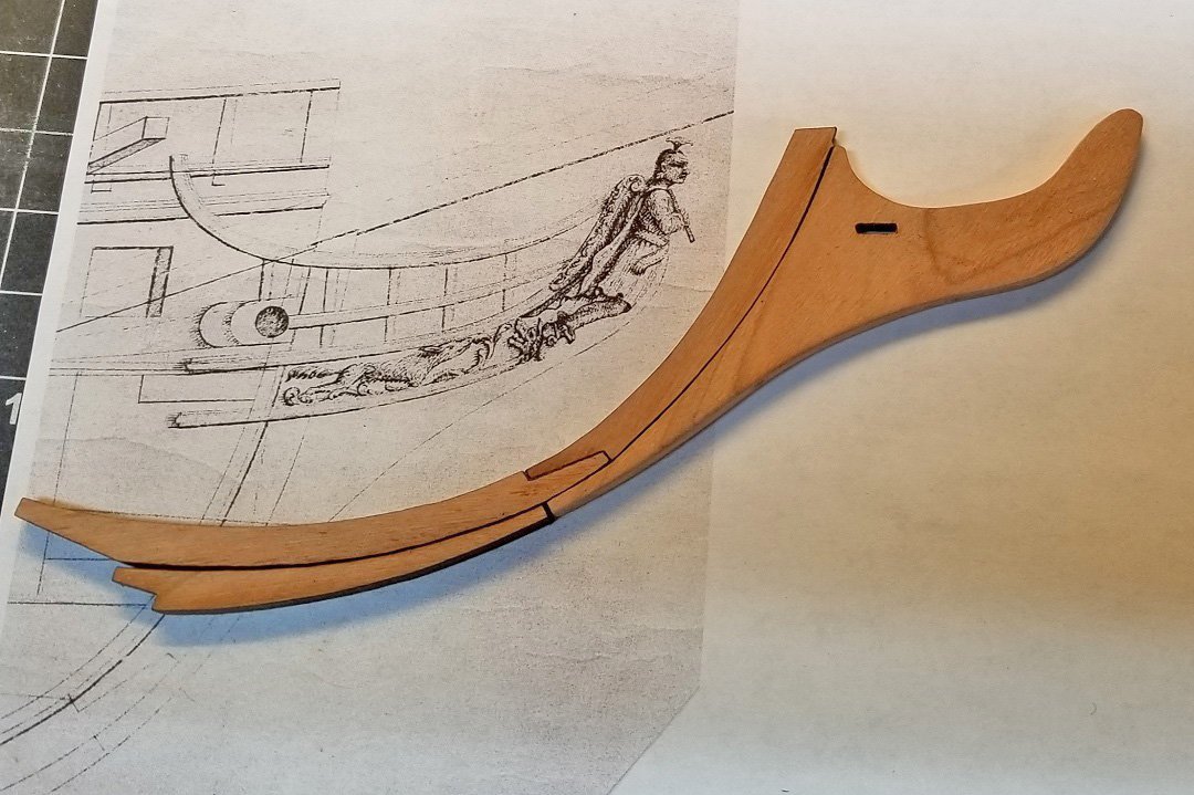
Cleaned up but not glued up.. Still need to make a seat for the figurehead, but that will come later.
- yvesvidal, mtaylor, GrandpaPhil and 6 others
-
 9
9
-
Yes, thanks Mark.
I also realized I needed to cut those pintle slots a little deeper.. Version 3 is in the wings.
I'm sure the average kit model will never have the details as they should be, and Model Shipways is usually better than most.
I have this problem that I cant leave well enough alone..😄
- Oldsalt1950, Dave_E, mtaylor and 1 other
-
4
-
I thought it might mean something like that, but I see topics that are days and weeks old that haven't changed since my last visit..
- thibaultron, Canute and mtaylor
-
3
-
What does the red box with the word " New" mean?
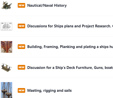
Just wondering, cause all forums show that for me..
-
Just a little more detail to Ponder. You may run into a problem using the planking fan if you don't have wider planking stock than that provided in the kit.
However you can work around this by using stealers at the stern. Marquardt's drawing shows at least two stealers and they can be used to accommodate the increased space compared to midships.
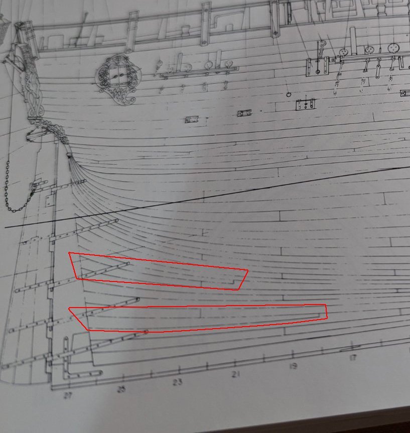
I've highlighted the two stealers I see. The stealer makes two planks become three.
At the other end, there is less space, and tapering will take care of that. However, you don't want the planks at the stem to be too narrow. I believe no more than half a full size plank.
This can be mitigated with a ' drop ' plank. I don't know if Marquardt's drawings show any of those.
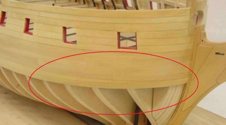
Here is an example from Chuck's Winchelsea. Two planks become one.
Please forgive me if I have made undue assumptions about your knowledge or lack thereof regarding stealers and drop planks. ( Some references refer to drop planks as stealers also. )
-
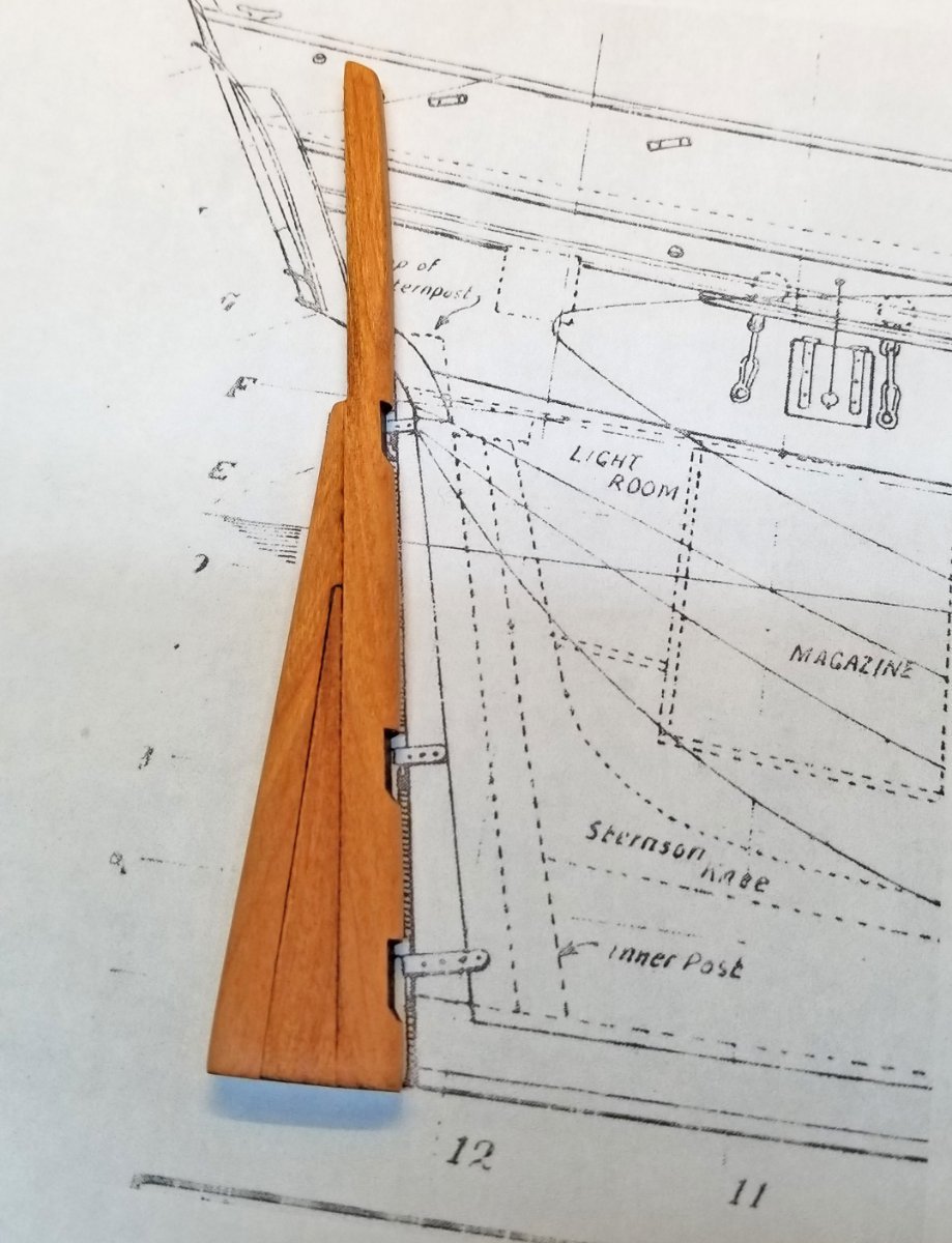
A tale of two rudders.
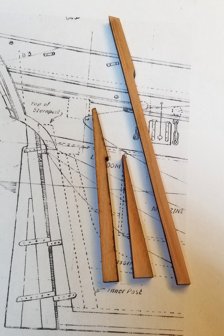
I cut out some pieces to build the rudder.
Glued it up and did some preliminary finishing while contemplating cutting out the slots for the pintles.. And thought, 'why didn't I do that with the laser?'.
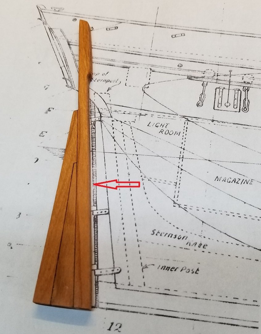
Then came my Uh-Oh moment.. I didn't realize when I traced the parts that the shaded area was part of that section of the rudder, and where the pintles would go.

Fallback, regroup and make some new parts.. Should be able to go forward with this
( Looking at the picture now, I'm not sure I can live with the fit of those parts. It may look better on the other side. I'll have to
think about it. )
Ooops. Just noticed I wrote ' gudgeons ' when I meant pintles. Fixed.
- mtaylor, Edwardkenway, yvesvidal and 4 others
-
7
-
Very nice work. I envy how you have been able to progress the way you have in a relatively short period of time..
- Dave_E and Keith Black
-
2
-
The head rails are so far above what has ever been part of a kit..
While I may not build the Winchelsea, it is like master ship modeling school to follow along and anticipate using your ideas in my future builds.
-
No need to apologize.. There are more builds that never get finished compared to those that are..
Too bad we all cannot get paid to do this, and be able to pay someone else to do the chores that take us away from ship building.
- Knocklouder and Dave_E
-
2
-
If I may, I seem to remember Chuck discussing this way back when. Not sure if it is Bulkhead 21, but here is the mention.
- FrankWouts and Ryland Craze
-
2
-
9 minutes ago, desalgu said:
the mast bands or bindings (not sure of the correct term).
Those are called " wooldings " ... Don't ask me why.😁
- Dave_E, bruce d and chris watton
-
3
-
2 minutes ago, BenD said:
I've tried Crochet yarn before and it doesn't make the best rope.
The original posts seems to be talking about using it off the spool for rigging line.
I would be curious to see examples in various sizes that have the appearance of rope.. The crochet thread I have seen wouldn't work for me..
- Dave_E, mtaylor and thibaultron
-
3
-
I would say a drawback, is that it doesn't have a rope-like appearance.
- thibaultron, allanyed, Dave_E and 1 other
-
4
-
2 hours ago, allanyed said:
.....blocks up to about 16"
Anything above 6mm would be a really good exercise in making one's own blocks..
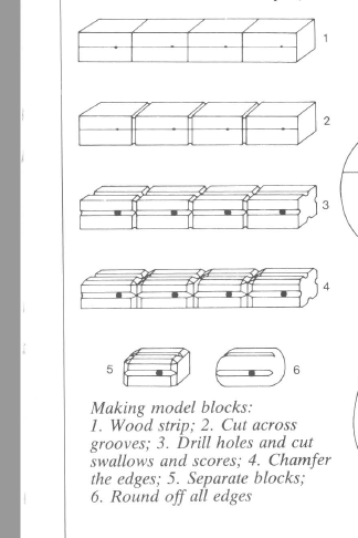
If you have a small table saw, this method from Mondfeld would be a breeze..
- Dave_E, Keith Black and Ryland Craze
-
3
-
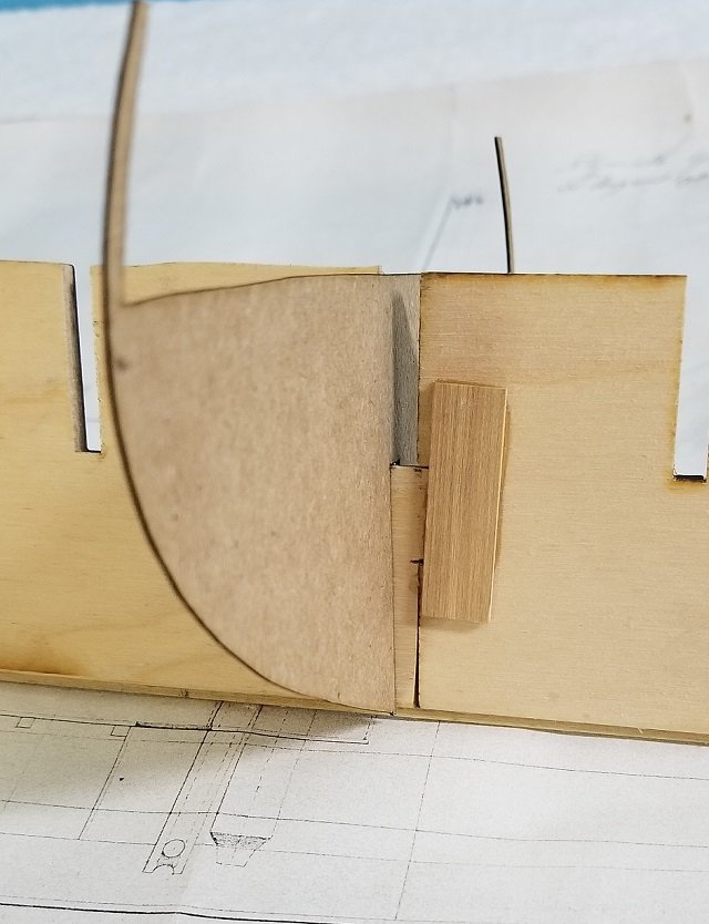
Thanks for the reminder... No exposed plywood edges in my world..
I will be adding a built up stem and keel..
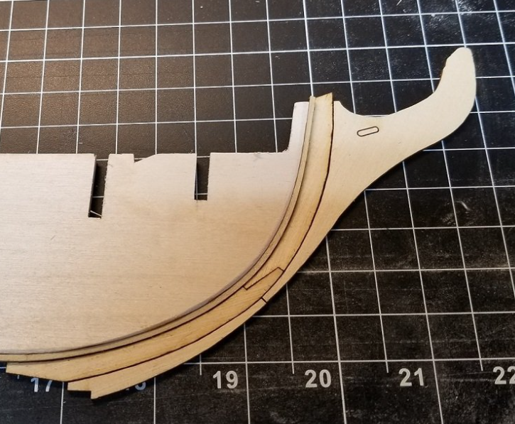
This is a test cut from some thin scrap.. I tentatively plan on using cherry..
- CiscoH, Edwardkenway, Teach. and 6 others
-
9
-
3 hours ago, Strelok said:
Is this true?
I really don't know..
Harold Hahn says the following in an article about his model:
QuoteThe Model Shipways plans credit Rattlesnake
with twenty guns. Chapelle says that the ship,
when taken into the British Navy and renamed
Cormorant, was rated for fourteen guns. Another
British source allowed sixteen guns. The
twenty-gun rating undoubtedly resulted from
the fact that there are twenty gunports. After
building the model, I question the usefulness of
the two forward gunports. Although occasional,
limited use for bow chasers might have been
anticipated, the space is just too confining to
permit guns to be handled in the usual way.
Therefore, my installation of ten guns on the
starboard side might well be questioned.
-
1 hour ago, Dave_E said:
Very nice! My hat is off to you guys with the equipment and the knowledge to do what your doing! 👍😀
You should see the size of my scrap pile..😁
- Dave_E, mtaylor and Edwardkenway
-
2
-
 1
1
-
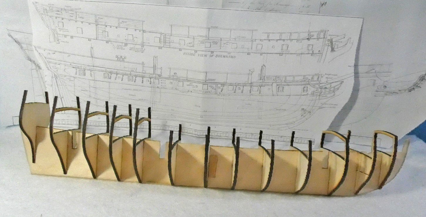
All of the bulkheads are cut.
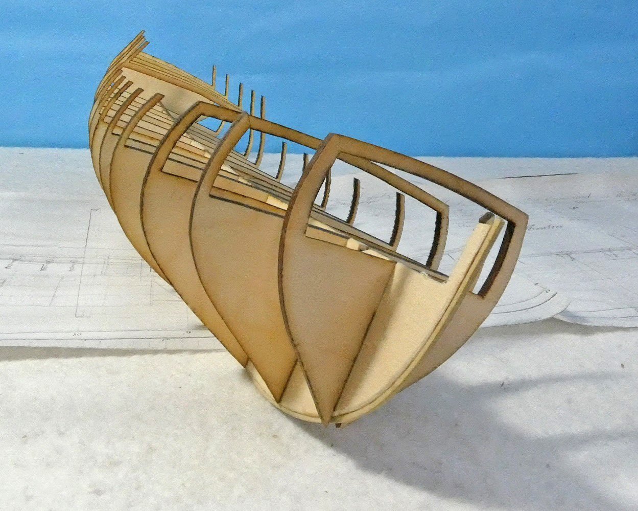
The dry fit is very tight. I did a lot of test cuts with the slots and it paid off.. They all slid right in with no forcing and virtually no wiggle.
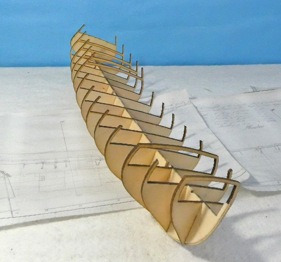
Another angle. There are some slight adjustments to be made for the rabbet and bearding lines..
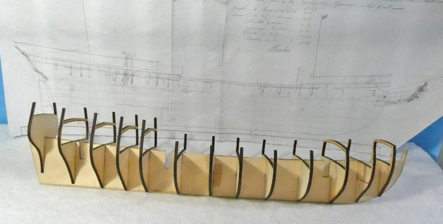
Here is the skeleton next to the 1:48 NMM drawings.

...and the MS 1:64 plans.
I do plan to do some filling between bulkheads. I will be experimenting to see what it takes to get a fair run of the planking, which I hope to be one layer..
My hat's off to the MS builders who are expected to plank with bass in one layer..
-
Today I thought I would talk about my workflow for copying the plans and cutting out parts.
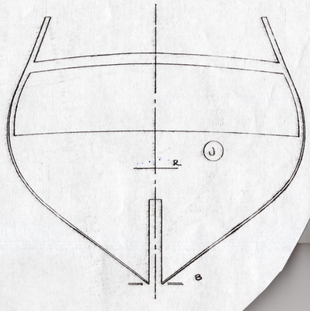
I use an Epson V39 scanner to scan the plans, which does a good enough job for my purposes. I scan at 600 DPI, which is possibly a bit of overkill, but gives me some wiggle room for moving between applications and ultimately gives me a finer laser cut, which wouldn't be a problem if were using a vectorized drawing, but that is for a discussion on another day and a different project.
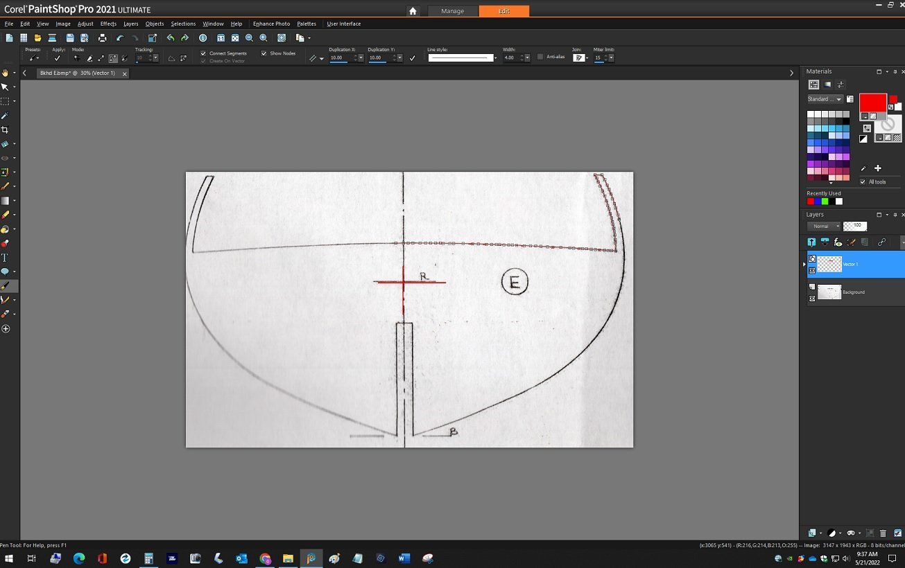
I Use Corel PaintShop to trace the scans, because it has a pen tool I really like .
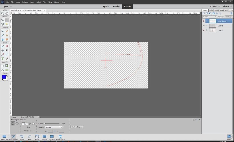
I then use Adobe PhotoShop Elements to create the templates for the laser. I could probably do all the work in Corel, but I have been using PhotoShop a lot longer, am comfortable with the interface and don't feel like trying to mess with the learning curve at this point. I only trace 1/2 of the scan, then copy and flip it to get a symmetrical part. I found the MS drawings to be pretty accurate with some very small but negligible symmetry issues for my purposes. Plus, only tracing half the template saves some time.

The completed template. The blue outline of the slot is and adjustment to get it to the 5/32 of my stock. Upsizing from 1:64 to 1:48 made the slot bigger, and had to be adjusted for.
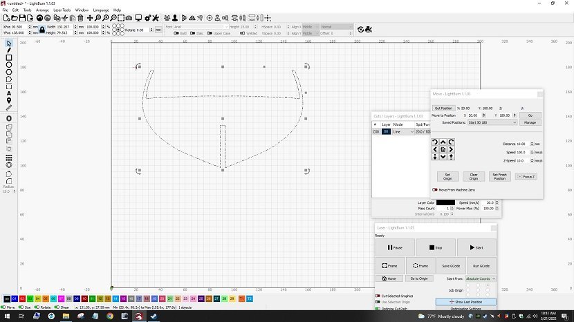
I drive my laser with a program called LightBurn. It is a very powerful laser controller which gives me virtually infinite control over the power output and speed of the laser, which is essential for different materials and thicknesses. It also traces and vectorizes my images, further reducing any jaggies that may have been part of my drawing.
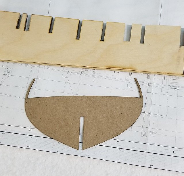
I cut out a cardboard test part to check for fit.
Fit at the rabbet is particularly important. I can make any adjustments before wasting my production material.
That's about it for workflow at this point. I hope to make some progress on the skeleton this weekend.
- Dave_E, yvesvidal, Edwardkenway and 6 others
-
9
-
Here's my .02 on a block tumbler/buster.
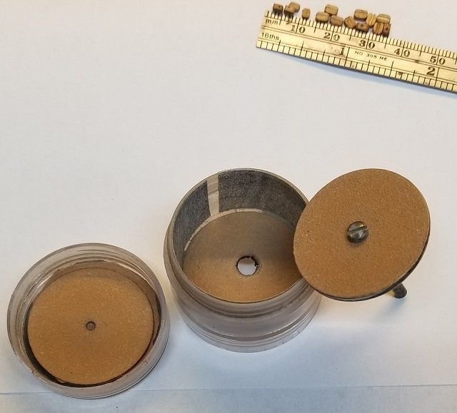
I made this little guy out of a little parts keeper with a screw on lid. Lined with 400 grit sandpaper. The disc moves freely up and down
to make the parts bounce around and up and down.
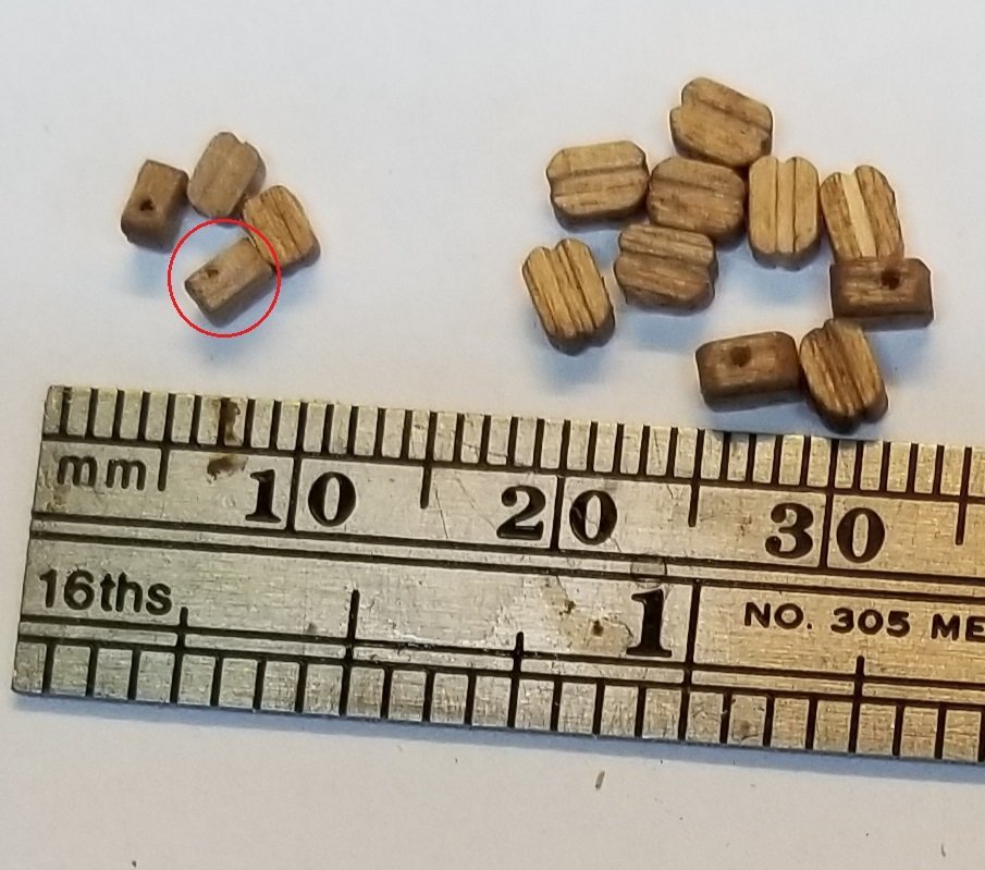
Here are the blocks that came with my Model Shipways 18th Century Longboat. 3 and 4 mm.. Note the red circle. Block is not useable.
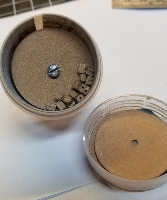
Blocks inside my tumbler.
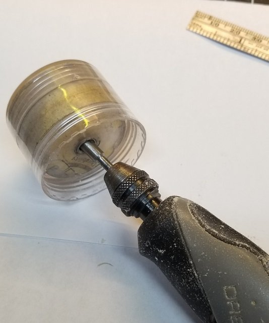
Cap on. I hold the container and run the mini Dremel at about 1-2K for a couple of minutes.
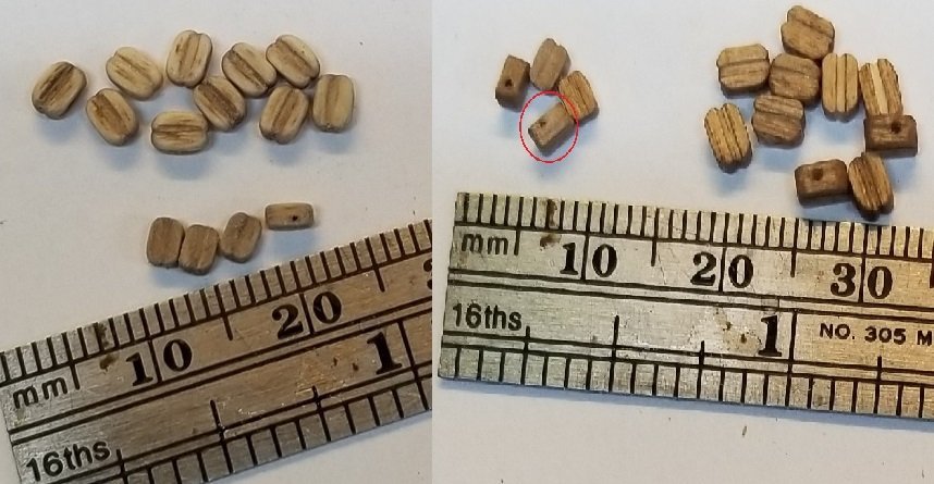
Here is the result on the left. Some improvement, but nothing to compare with the good aftermarket blocks.
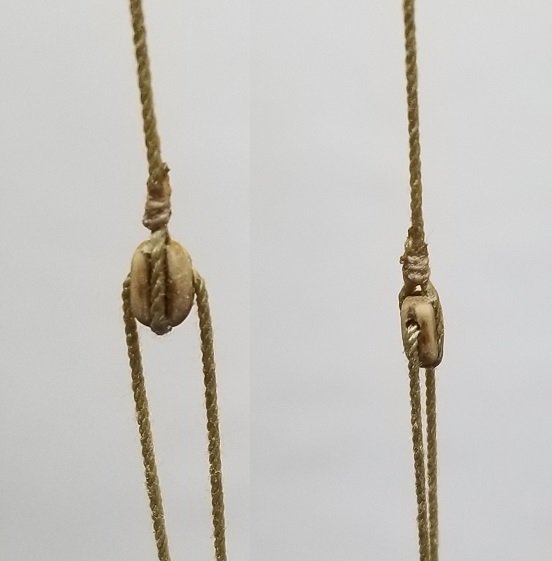
Here is one of the 4mm stropped up. Back away ten feet and they are not bad at all..
Another problem with the kit blocks are the defects. Even if the sheave hole is in the right place, the groove needs to be deeper and at least as wide
as the hole to look right. A lot of kits don't have enough to begin with, and the defective ones will have to be replaced.
Before I go here is another use I found for my little tumbler.
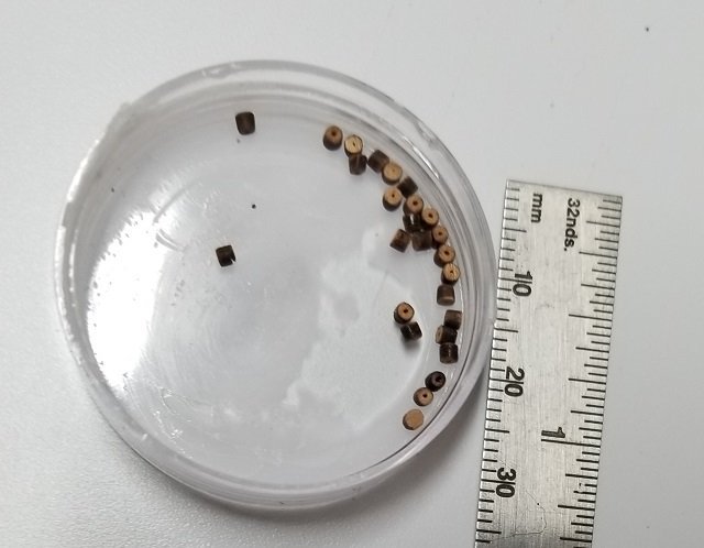
I cut out these wood beads with my laser.
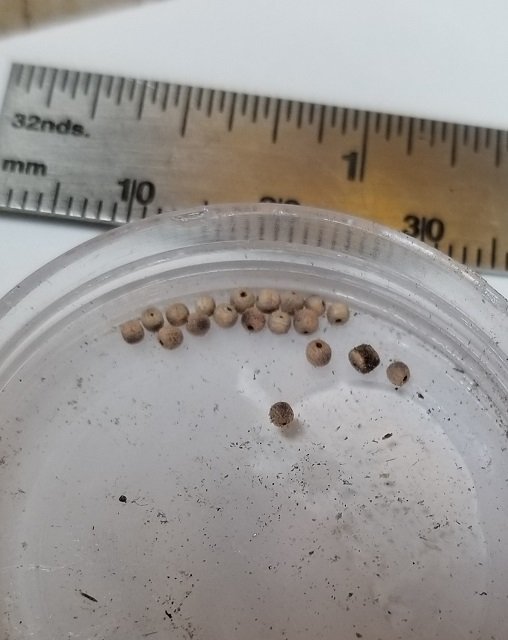
Here they are after tumbling. ( Ignore the one that didn't round up like it should have. It got trapped in the tumbler somewhere )
I was experimenting with making some parral beads.
- Keith Black, Landlubber Mike, bolin and 4 others
-
6
-
 1
1

Albatros by Dr PR - Mantua - Scale 1:48 - Revenue Cutter kitbash about 1815
in - Kit build logs for subjects built from 1801 - 1850
Posted
I have had no trouble getting it at Amazon..