Dan Vadas
-
Posts
3,261 -
Joined
-
Last visited
Content Type
Profiles
Forums
Gallery
Events
Everything posted by Dan Vadas
-
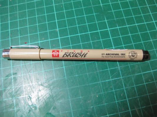
This is the one I use. It's a "Brush" width, and I use the side of the pen rather than the tip. The Sakura should work fine also : Danny
-
Do ONE side of the plank and ONE butt join BEFORE you glue them in. Make sure the EDGE of the plank is smooth by lightly sanding out any lumps and bumps before applying the ink. Danny
-
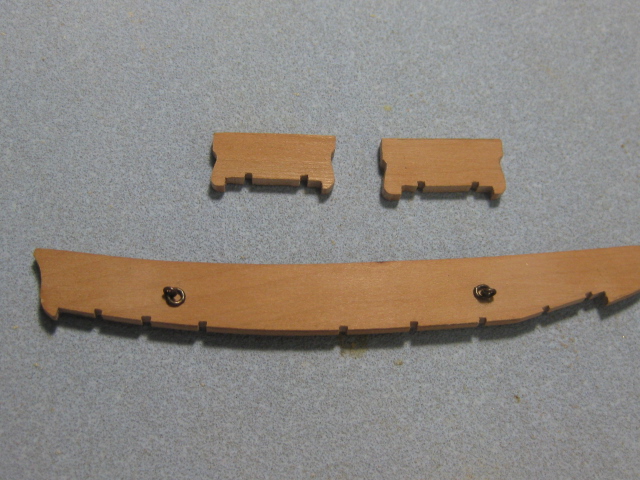
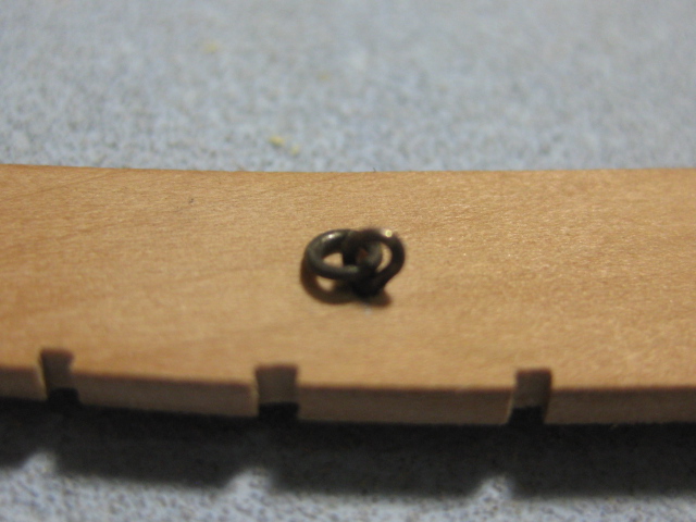
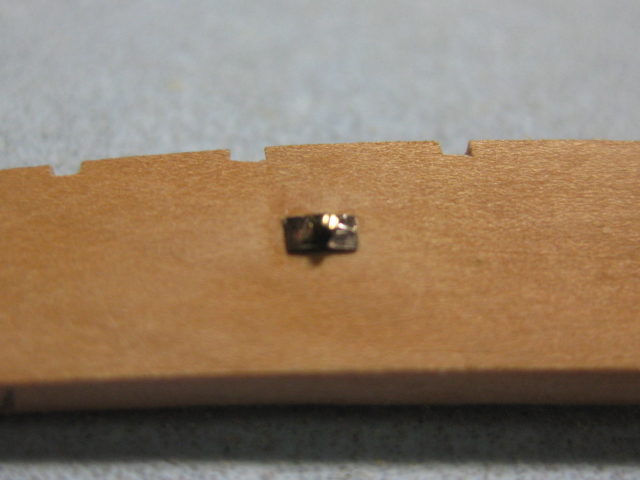
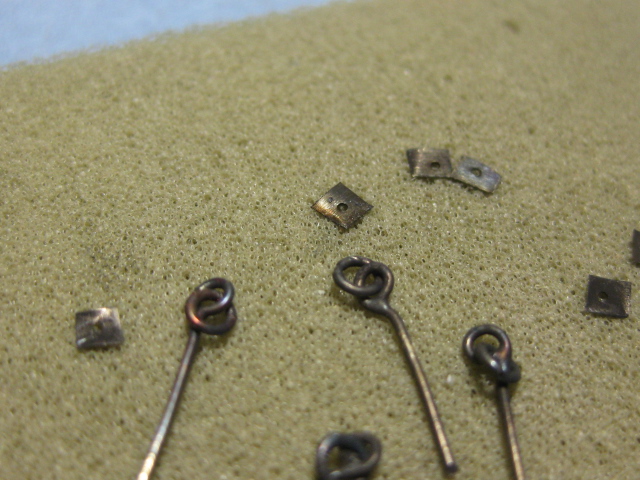
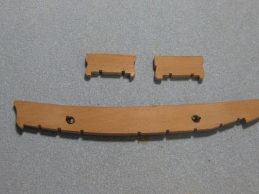
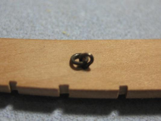
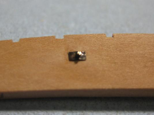
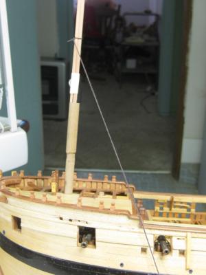
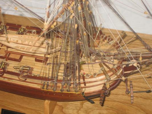
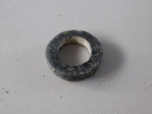
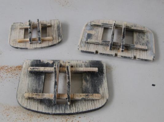
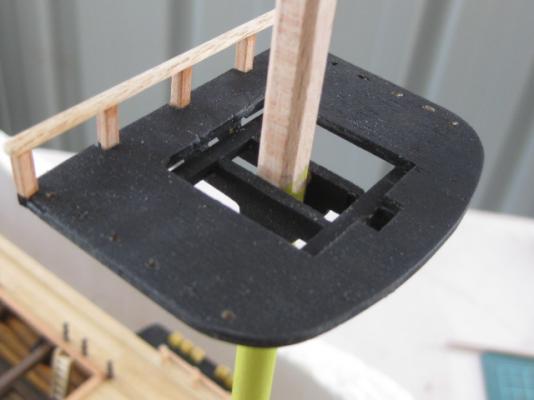
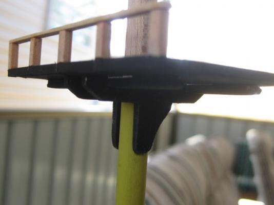
Hi all, back from my holidays again . Channels I've made the Foremast Channels and the Stools that are fitted just aft of them. They are tapered outboard from 4 1/2" to 2 3/4" (real size) on their bottom face. There are two swivelling ringbolts in each channel - they fit through a small plate on the underside which I made from thin brass shim material and blackened : I've cut into the Sheer Strake for added support on the inboard edge. This is only a dry fit so far : To align the slots for the Shrouds I rigged up a dummy mast and used a piece of thread to ensure they wouldn't foul the gunports and sweep ports. A molding will be added to cover the shrouds after they are fitted. The dummy mast is vertical, not on the angle it seems in the pic (the ship itself is tilted a bit ) : Danny

-
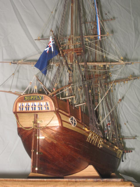
Hi Grant, There's a Third Option - make the Yard Tackles look like they are REALLY doing something by hooking them up to a Longboat ready for "Liftoff" like on my "HMAT Supply". Sorry about the camera angles, I can't find a clearer pic on my computer and you'll have to go to Norfolk Island and visit the Pier Museum to see the model . Danny

-
Hi Toni, That's the same shape Lower Capstan Step as my "Vulture". It's the actual step, not an addition on top. Here's the Link to the post in my build log where I made it. Danny
-
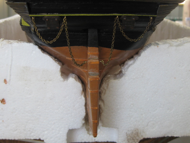
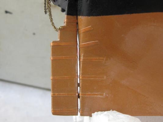
Last pics for now are of the Rudder I'd previously rebuilt and fitted and forgot to take pics of a couple of weeks ago : Danny
-
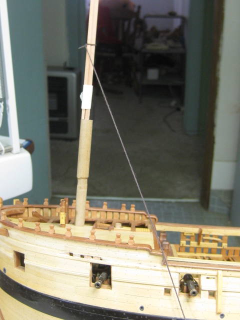
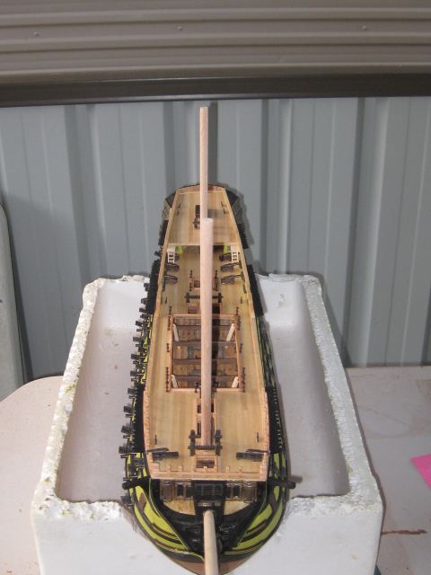
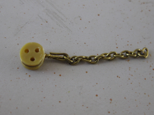
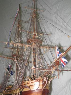
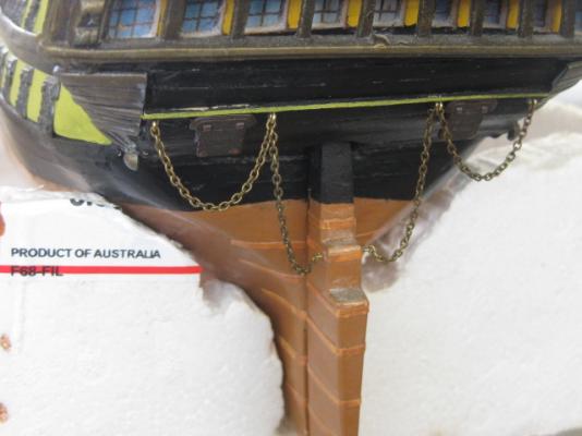
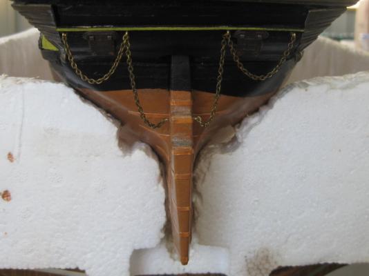
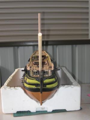
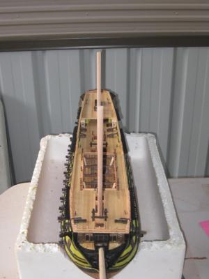
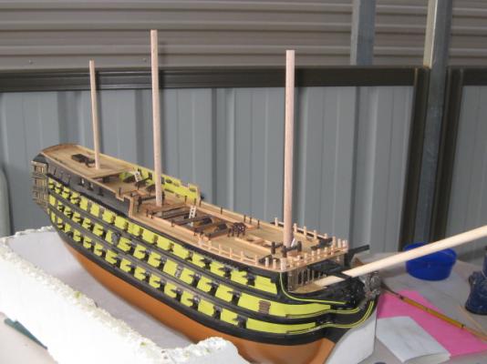
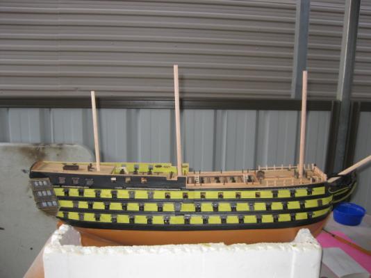
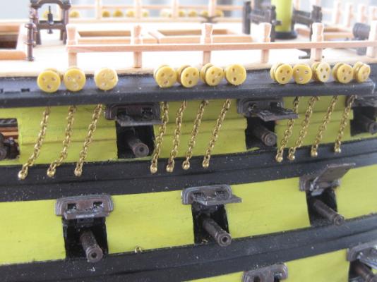
I rebuilt and stepped the Masts - this took nearly a full day, as the holes on each deck and the bulkheads below them didn't come close to lining up : I've also fitted about half the lower deadeyes and their chains - again, not historically accurate but that's what the kit supplied. The kit deadeyes aren't too bad actually - they are cast in Resin and the holes are better than most kits with wooden ones. The chains were already fitted to the deadeyes - I don't know if they came like this in the kit, but I suspect they did. It saved me a lot of work anyway : The loose chains will tighten up when I fit the Shrouds. There are also a couple of Gunport Lids that will need re-fitting - I managed to loosen a few while fitting the Chains .... I'll fit ALL the Chains before doing this, as no doubt I'll disturb a couple more yet. Continued in next Post .....
-
Thanks for the comments Bug, Craig, Daniel, Ollie, Grant, Craig and Blademaster . Not really Ollie. I estimate about 45 hours so far. I managed some more work on the model over the (looong - mine started on Wednesday ) Australia Day weekend. The old guy had "built" the Masts, but they were so rough and out of shape that my easiest option was to scrap virtually everything and start over. I kept the Mast Tops, as I didn't have anything on hand to replace them with. I soaked them overnight in Acetone to soften the glue and paint, then cleaned them up. Below are a couple of pics of the Tops and a Mast Coat from BEFORE : And some pics AFTER : I realize that the Tops are nowhere near accurate, but don't forget I'm attempting to build this model the way the old guy would have liked it to come out . Continued in next Post ......
-
John, a word of advice from someone who's "been there, done that " - fill in the gaps in the cant frame errors NOW before you forget later and glue them to the AFT cuts . It would only take an hour to glue in some 1/8" wide scrap wood and get them right. Danny
- 745 replies
-
- 1
-

-
- francis pritt
- mission ship
- (and 1 more)
-
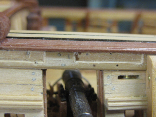
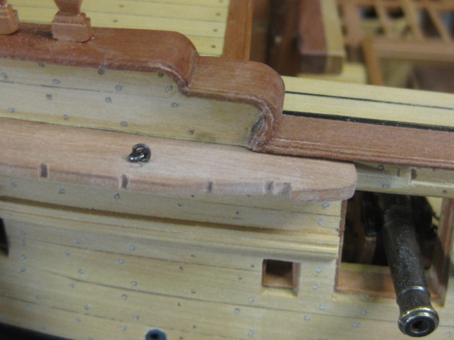
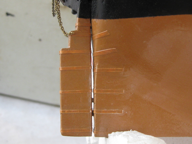
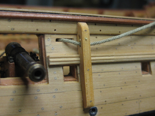
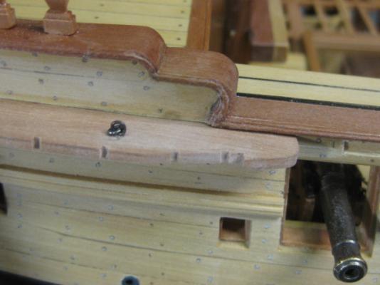
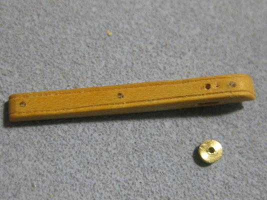
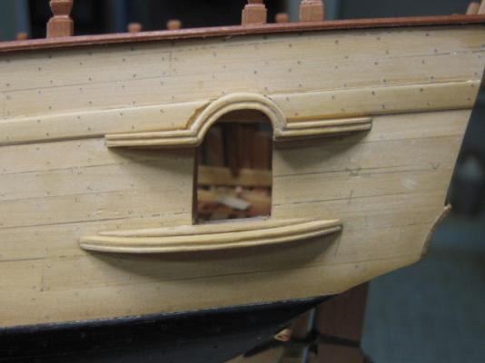
Well done Sailor, that's one of them. When marking the position of the sheave I marked the centre pin and forgot to allow for half the height of it. It's 1.3mm too low. The other mistake (apart from the "ding" that Mark mentioned) is in pic #4 of my last post. I made the slot for the first chesstree too long - there shouldn't be such a large gap ABOVE the sheave. I can live with these mistakes (hardly seen by eye) but WILL learn from them . Thanks Colin - the holes are empty. I was going to put blackened brass "bolts" into them but there's no point - they will be completely covered by the Sheer Rail. Thanks also for the nice comments David and Jan. Danny
-
Oops .... forgot about that one. That makes THREE mistakes . Thanks Mark Thanks too David. I wish you well on your journey to the "Dark Side". Danny
-
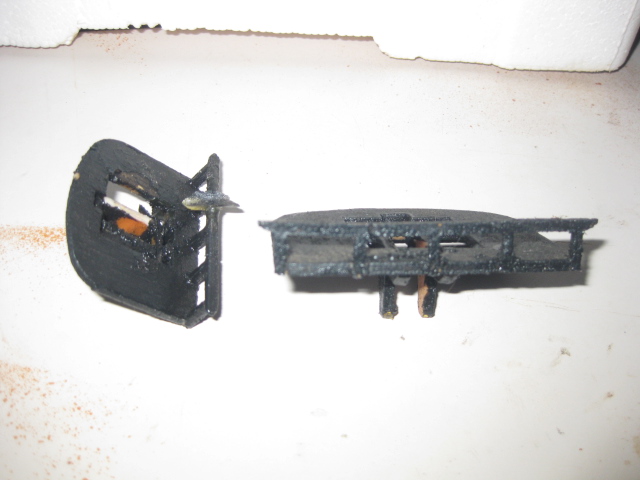
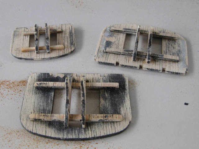
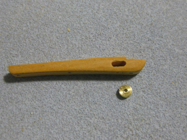
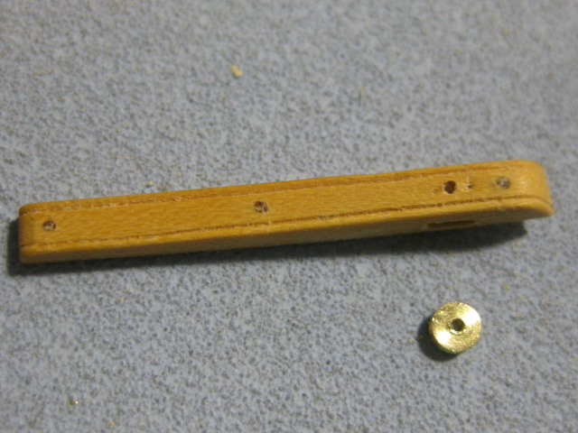
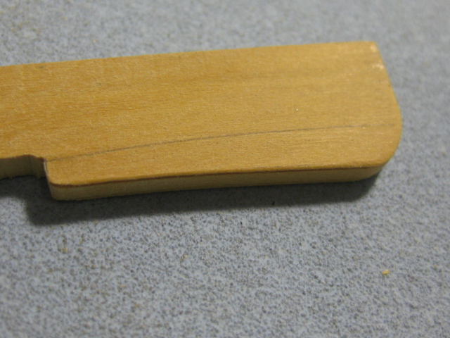
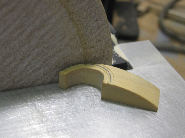
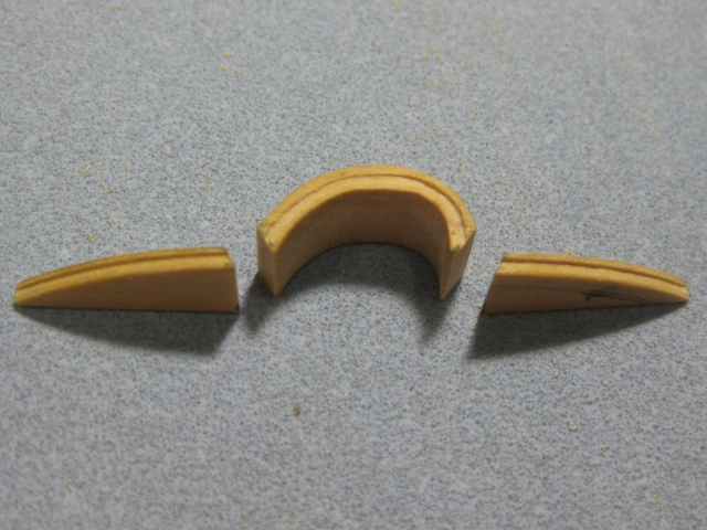
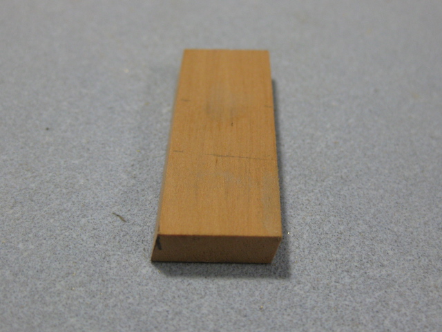
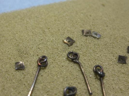
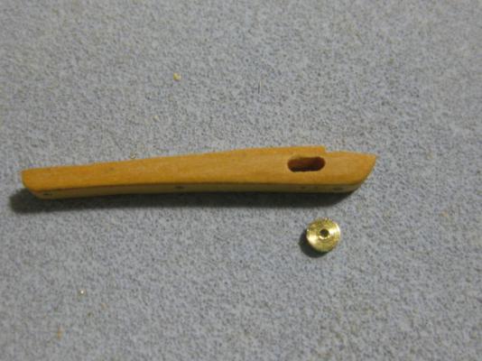
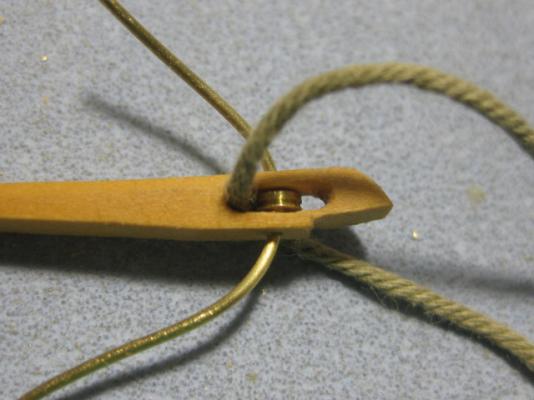
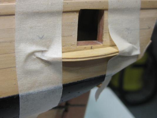
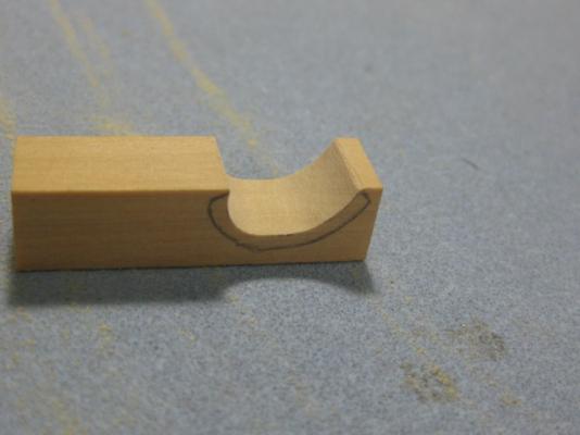
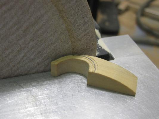
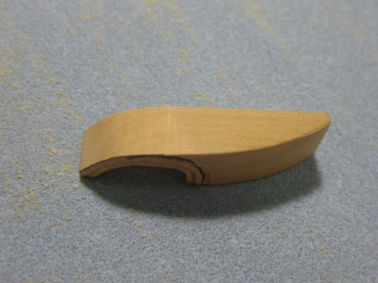
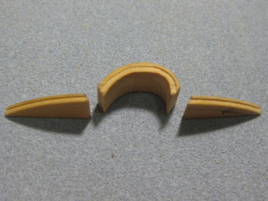
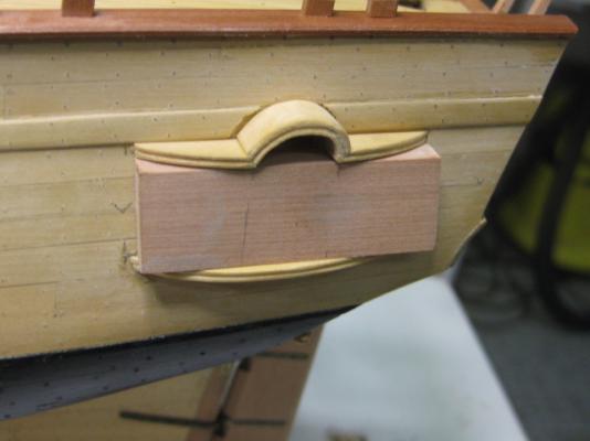
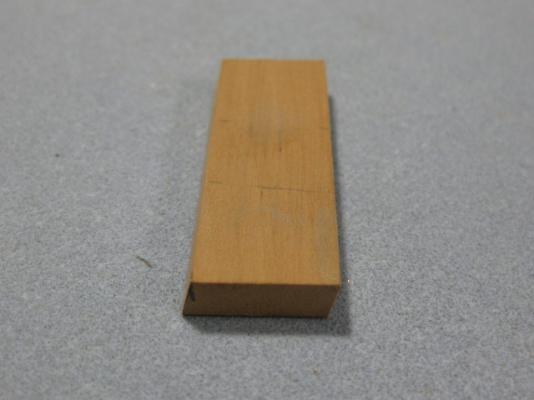
Chesstrees The Chesstrees house a sheave that acts as a "lead" for the Main Tack before it enters the forward Fixed Block and then belays around the cleat. They are positioned just aft of the fixed block. I made the two chesstrees from English Box, both as a color contrast and because of the thin section around the sheave which required a very close-grained timber to avoid splitting. The first one was a "character building exercise" - it took me about 2 1/2 hours to shape. The second one took about 10 minutes . The (working) sheaves are 2.65mm in diameter and 1mm thick : The second chesstree ready to cut off the piece of stock - after taking this pic I prepared everything (molding on the outer face, sheave hole and "bolts") for this one before cutting it off : The Main Tacks are quite large - 5 1/2" in circumference, the scale equivalent being 0.9mm diameter. I threaded some line through both the chesstree and the fixed block to make sure I'd made the slots large enough to pass the line through : I made two mistakes (which will remain) on the first one - anyone spot them ? Danny


-
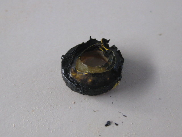
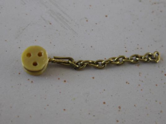
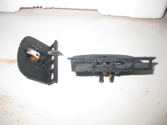
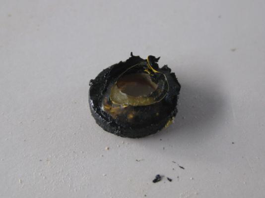
Thanks Christian, David, Yambo and Pat . Pat, believe it or not just the plastic top from a nail packet. It isn't totally clear, which gives the more textured look of old-type glass . Danny
-
Santisima Trinidad: Occre vs DeAgostini
Dan Vadas replied to mangaroca's topic in Wood ship model kits
In a word - NO. It's way too soft and will distort over time and use. I'd use Pine, which you can get cheaply enough at any hardware store. Danny -
Hi Pat, Here's an obvious word of advice - DON'T WORK IN YOUR LAP . This is what we use Building Boards for - whether the "right way up" or upside-down. Or even Tilting ones . Just don't forget to screw the keel to the board, or you might get the same nasty shock I did when (despite all the best laid plans of mice etc ...) mine DID crash to the floor breaking the Stem . Danny
- 517 replies
-
- 1
-
-
- Endeavour
- Artesania Latina
- (and 1 more)
-
Thanks Greg, and yes it is. Leaving one side "in frame" has saved me a mountain of double work so far . Thanks again John. Danny
-
I'm guessing none of the above members are either Kit Builders or don't own a Byrnes Table Saw - that would be my pick. I use mine a lot more than I do my Mill. 9 times out of 10 I can get by with a Pinvise instead of my Dremel (unless I'm drilling a couple of thousand Treenails in one go . Danny
-
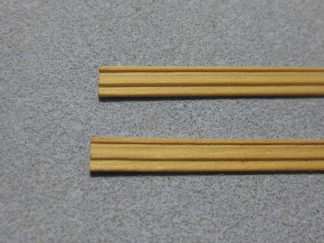
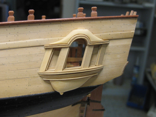
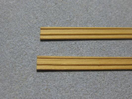
Thanks for the tip Mark, but it would have to be a VERY small chess set - the Crown is only 4mm high . Pilasters The final pieces of this jigsaw puzzle - the Pilasters. The first pieces I made were the Bases and Capitals. These were cut from a length of molded English Box : The Columns were done in similar fashion, from long lengths of molded stock : Some pics of the finished assembly ready for a coat of Minwax : Danny

-
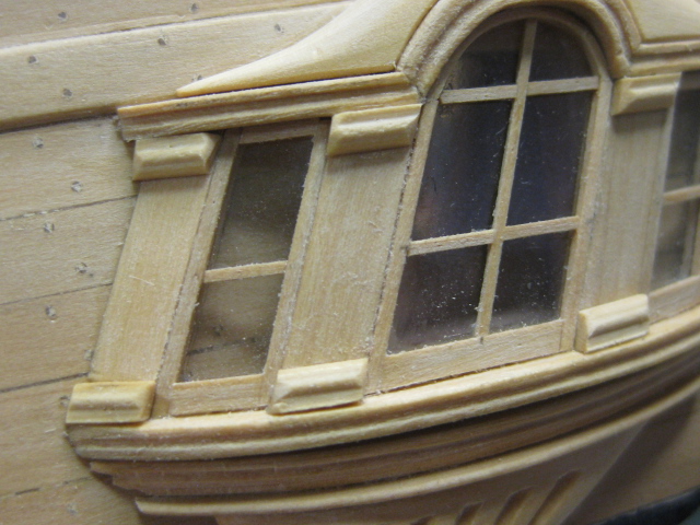
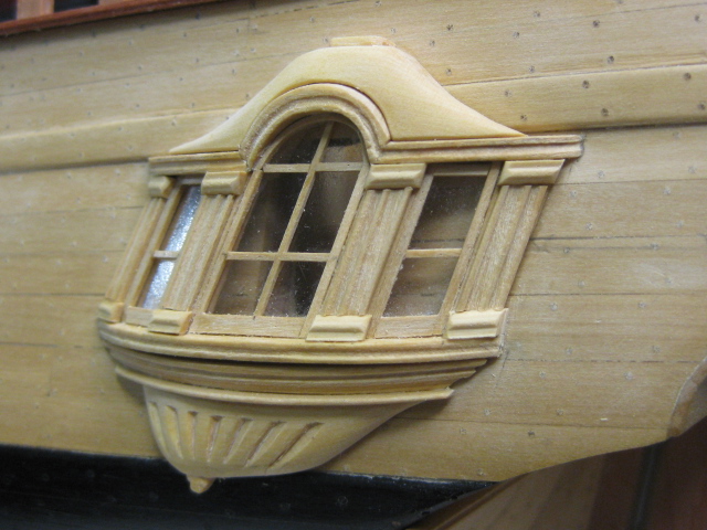
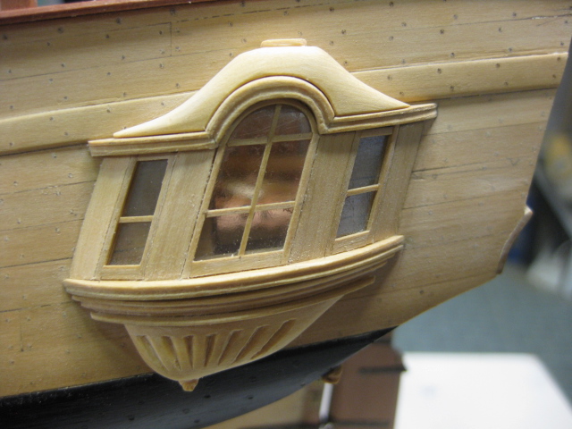
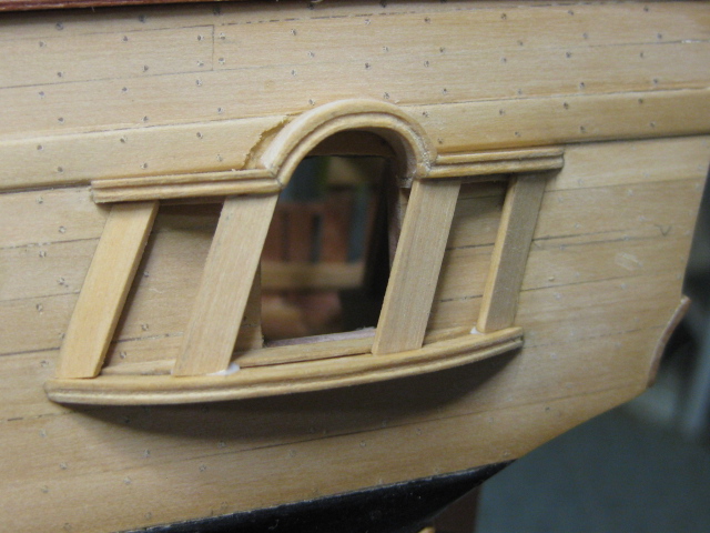
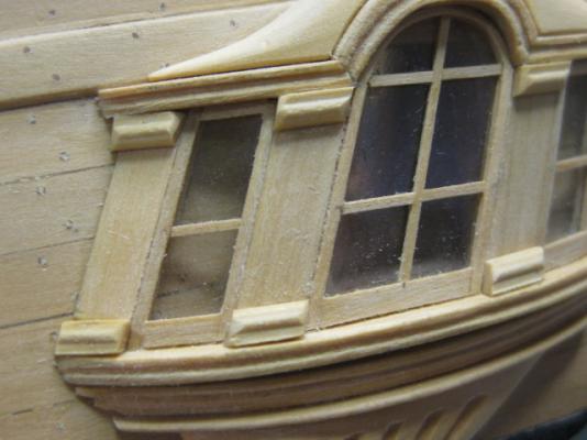
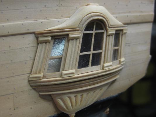
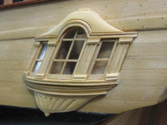
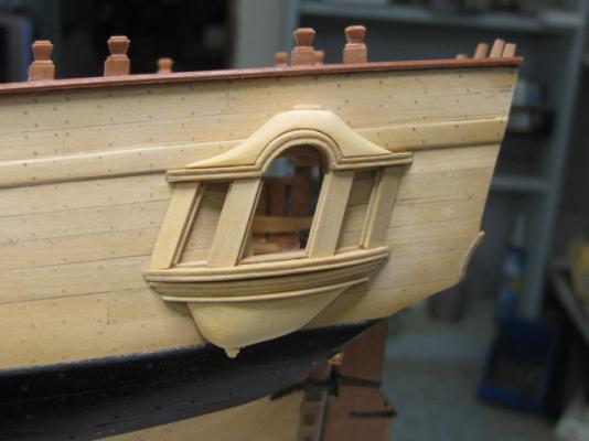
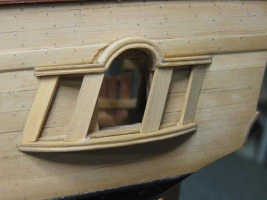
Thanks for the comments Christian, Remco, John. Grant, Toni, Mark, Joe and Ben. Also all those who "Liked" the post. Much appreciated . Carving the Finishing and Glazing Lights Mark, as per your request - the carving on the Lower Finishing : I won't be doing any of the "fancy" carving for quite a while yet if I do any of it at all, I'm still undecided - I don't have the tools, and my skills don't extend to the "artistic" type carving yet. Perhaps I can persuade Janos to make a few for me (hint, hint Janos ). I've also "glazed" the Lights with Acrylic (Perspex) and made and fitted the frames and munions. The curved frame in the central light was done by soaking and bending the strip : Almost finished with this very enjoyable project. Just four Pilasters to make. Danny


-
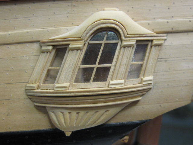
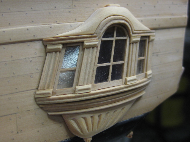
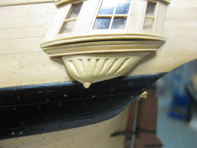
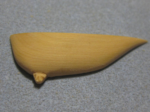
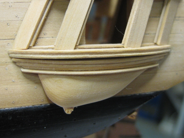
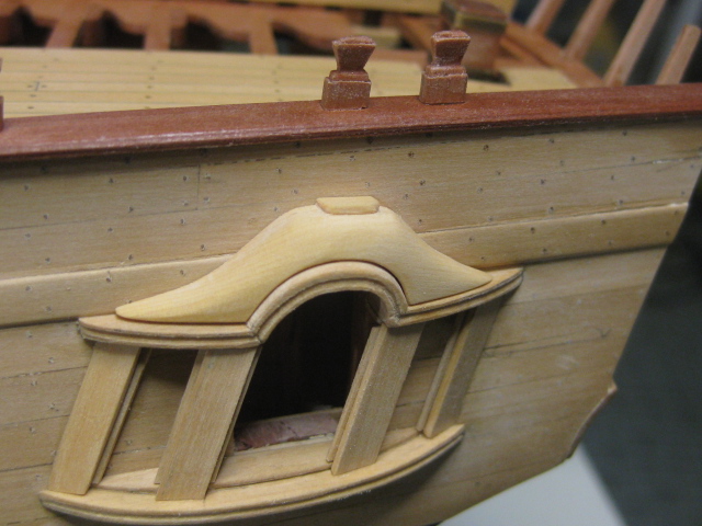
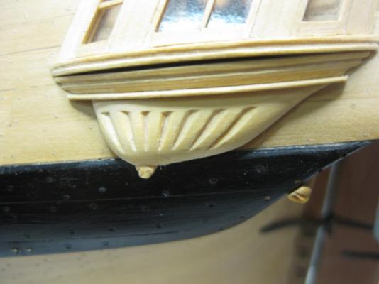
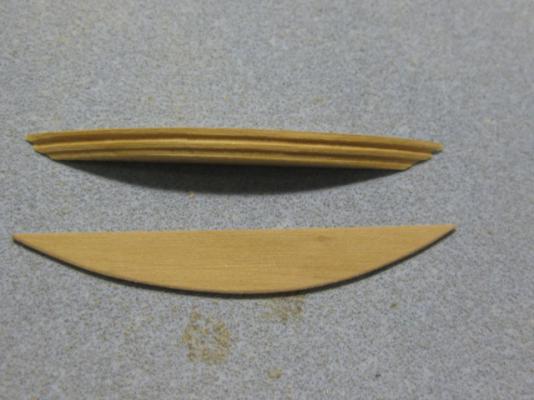
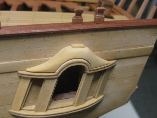
But wait John .... there's more . Lower Finishing The Lower Finishing is done in three sections - upper and lower sections divided by the Lower Finishing Rail. I first made the upper piece, which is sanded inward on it's lower edge by about 25 degrees. I then cut the molding in.Then I made the rail and glued it to the bottom of the upper piece : The lower piece was a bit harder to make, as I incorporated the Drop (the fancy round bit at the bottom). I carved a representation of three "leaves" into the drop : The last bit was easy - glue the two assemblies to the bottom of the Quarter Badge : Some carving still needs to be done to both upper and lower finishing pieces. This should be fairly easy with all parts fitted to the hull (I hope ). Danny


-
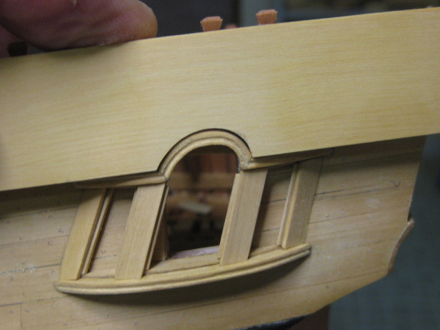
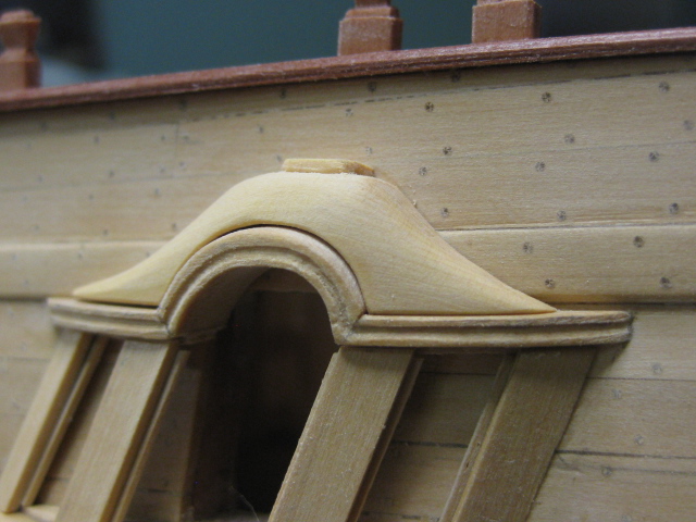
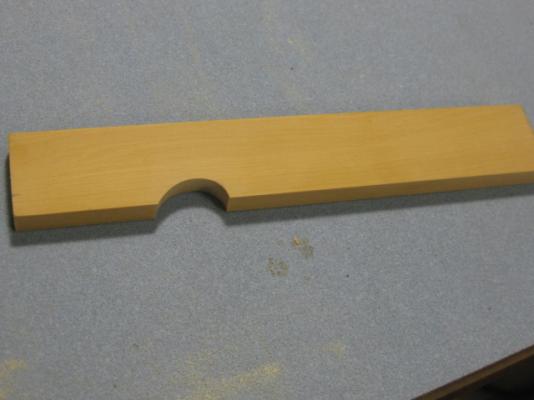
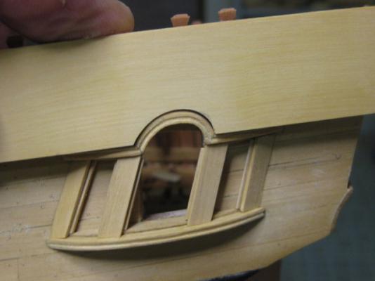
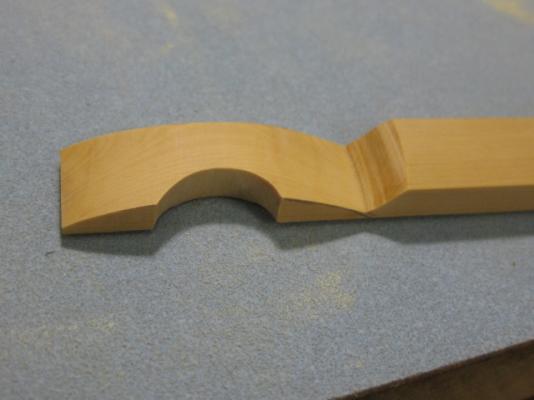
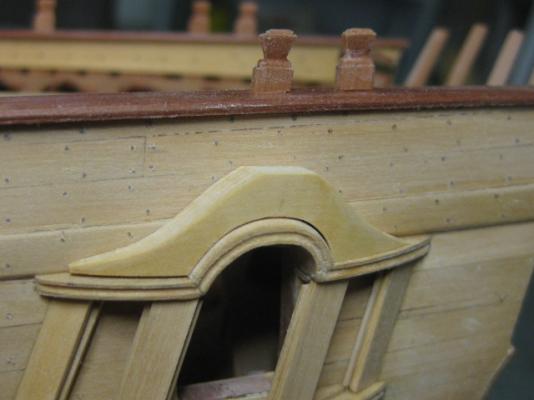
Thank you Greg - no, the case made it to the bedroom but I DID turn on the workshop lights on my way past . Garry ..... is that you ? Thanks Steve . Thank you too John. Upper Finishing Work continues on the Quarter Badge. Here is the Upper Finishing under construction. I made it from English Box. The first step was to cut out the lower portion to fit around the bell : Then I finessed the inner face to fit tight against the hull planking : The outer face was sanded down to fit the curvature of the upper stool : Then the upper section was cut on the scroll saw : Finally it was rounded off. The flat section on the top will support a carving of a Crown, and the whole piece will be textured : Danny

-
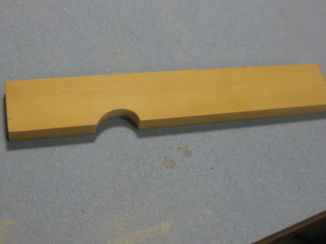
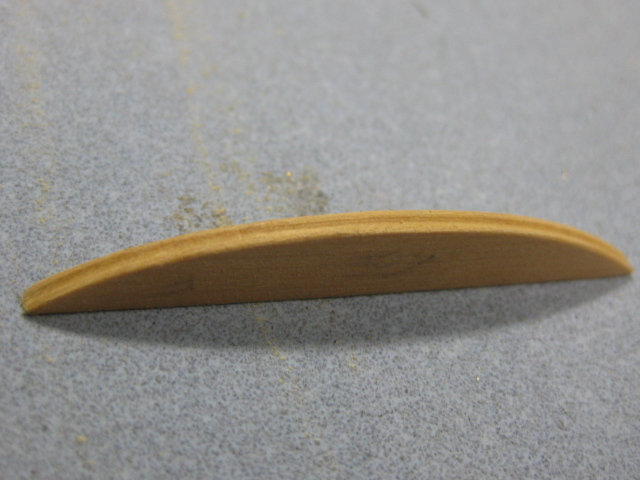
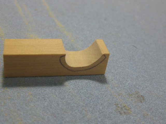
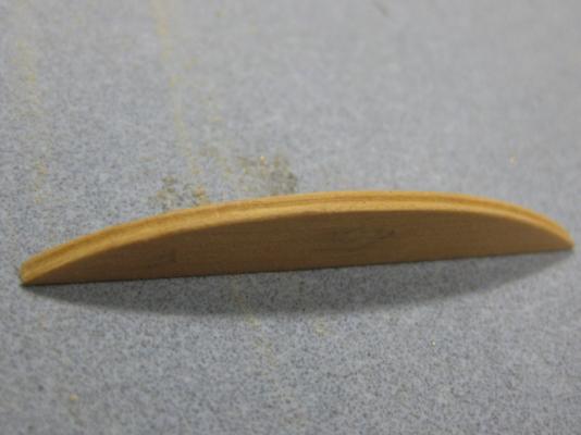
Thanks Druxey, actually it was quite easy. The hardest parts were shaping the molding around the end return and the small notch above the rudder hinge. Cutting the bevel only took one go (I must be getting better at doing things like that "by eye" ). Quarter Badge Stools and Munions This looked like being quite a challenge, but thanks to the instructions and tips in TFFM they haven't been too difficult so far (I haven't got to the Carving part yet though ). I'm only fitting a Badge to the Port side. The first pieces to be made, which the success of the rest depend on, are the Upper and Lower Stools. These took some careful measuring and marking out to get the right angles. In fact, I had a failure with the lower stool - I didn't have enough angle from the vertical (12 degrees) the first time I glued it in and had to get the Isopropyl out and have a second go. No biggie . I took the shape of the stools straight from the drawing in TFFM and cut two identical pieces. These need slightly different bevels on their inboard edges to keep the stools horizontal athwartships. Here is one stool ready for gluing in, the molding on the edge has already been scraped in : To assist in gluing them to the correct angle I used masking tape : The upper stool is quite a bit trickier to make than the lower one. It consists of three parts with a "bell" shaped piece in the middle. To make the centre piece I first cut out the lower portion from some thick stock, sanded the outer face to conform with the lower stool, then scraped the molding, and finally sanded the outer portion to shape on the disc sander : The joints are cut at a 45 degree angle. I glued the three pieces together before bevelling the assembly : To ensure both stools were perfectly parallel I used a piece of scrap with two bevels sanded into it as a spacer. The 2nd pic shows the spacer in use, but was only my 1st attempt before I realised I'd got the angle wrong : Take two, after I got the angles right : Last step to this stage, I've fitted the four Munions - more tricky angles, all done on the disc sander. The rough bit of cutting into the Sheer Strake above the bell will be covered by the Upper Finishing later on : Danny
-
Hmm .... I have quite a stash I bought cheaply from a former ship modeller - but you didn't hear it here, and NO it's not for sale . Danny
-
Hi Al, It should centre itself properly. If you're getting a wiggle there may be a problem with the collet (buy a new one) or your drill bit is bent (ditto). Drill through an appropriately thick scrap of wood and use that as a spacer against the shoulders of the pinvise. Filler can be made from the same sawdust of the timber in question mixed with diluted PVA. Glue the decks on BEFORE adding material to the frames to ensure they aren't pulled out of alignment and you need to add MORE material/sand off some. Danny