


dvm27
-
Posts
2,449 -
Joined
-
Last visited
Content Type
Profiles
Forums
Gallery
Events
Everything posted by dvm27
-
 Beautiful job, Lou. The marquetry is exceptional. The continuation of the deck planking aft up the face of the quarterdeck partition looks a bit unusual to me. Were you going to place a strip of molding at the transition? In addition to Doc Blake's exceptional model, perhaps this one from the American Marine Model Gallery will further inspire and provide a few rigging hints: http://www.shipmodel.com/files/fair-american-full-hull-webfair-american003.jpg
 -
Pandora by marsalv - FINISHED - 1:52
dvm27 replied to marsalv's topic in - Build logs for subjects built 1751 - 1800
Sweet work, Marsalv. I assume you added the molded edge detail with a scraper but I wonder how you got the corners and recesses so precise! -
Power Tools for a Fully Framed Build
dvm27 replied to ChrisLBren's topic in Modeling tools and Workshop Equipment
Does the Delta scroll saw have a tilting table top? I have a Dewalt scroll saw and use this feature quite often. -
Found this German company who carries much of the same micro hardware as Scale Hardware https://knupfer.info/shop/index.php/deutsch/
-
Thanks, Mark. BNA as actually a distributor for Scale Hardware. Note they have only a few items left. Once they've sold out that will be it.
-
I was hugely disappointed to learn that Scale Hardware, manufacturer or precision micro fasteners, washers, etc., is no longer in business. I've been unable to locate another source for items such as 0.5 mm brass washers, rivets and other simulated fasteners. Anyone know of a similar source of these products?
-
HMS Naiad 1797 by albert - FINISHED - 1/48
dvm27 replied to albert's topic in - Build logs for subjects built 1751 - 1800
Perfect work, Albert. The only thing that would make it even better is higher resolution photos! -
Always a treat to see your updates, Alex!
-
THE 74-GUN SHIP by Jeronimo
dvm27 replied to Jeronimo's topic in - Build logs for subjects built 1751 - 1800
Amazing work, but it is CGI isn't it? -
Very nice Giampiero! I find it difficult to get the blocks and hooks in the proper proportion...hooks always seem a bit too big.
-
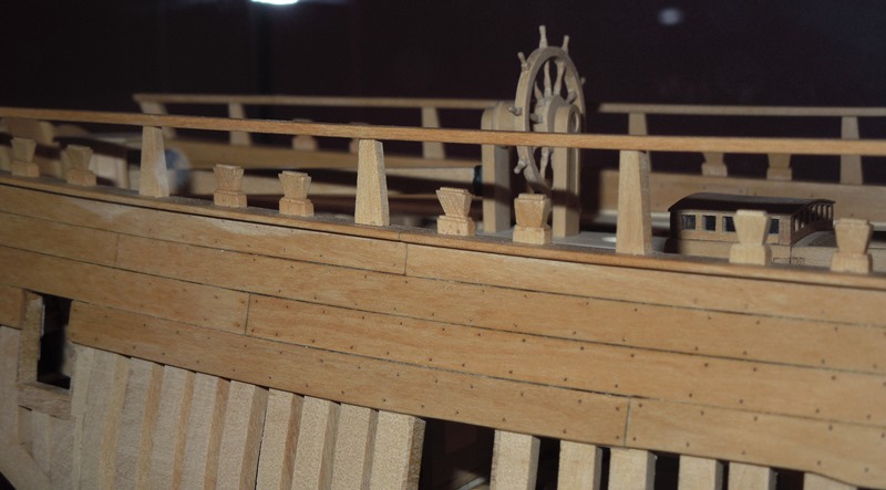
I wouldn't worry too much about the timberheads and quarterdeck stanchions at this point, Kevin. I think you will find them much easier to shape off the model then installed later after the various plankshears (rails) are in place. The most important thing to do is to get the toptimber levels correct, with smooth graceful lines. They are also parallel athwartships. This is much easier to do without timberheads and stanchions in the way. Later on, you can form the various plankshears from two sections with slots left to receive each timberhead or stanchion. David illustrates this beautifully in his book.
-
Usually I just check the like button but every now and them I have to comment on a particularly nice detail. Well done, Sir!
- 3,618 replies
-
- 4
-

-
- young america
- clipper
- (and 1 more)
-
Ship Models, Their Purpose and Development From 1650 to the Present, by Brian Lavery and Simon Stevens and The Model Ship, Her Role in History, by Norman Napier Boyd. Every ship modeler would want these in their collection.
-
Congratulations on the production of your first chocked full frame. I guarantee your production will speed up as you move on. I usually make them in pairs (each station). There is a small drawback in not installing bevelled chocks. During the fairing process you may sand into the chock of the narrower face (fore face on the fore frames and aft face on the aft frames). This could result in a wavy outside joint line instead of a parallel one. Probably would not be that noticeable as the wood tones down after time. I cut all the bevels for the chock on my Sherline mill. It's actually very easy to do. It is possible to do these with a chisel (David Antscherl certainly does) but I find it difficult to keep them consistent that way.
-
This is like a great foreign film...without the subtitles!
-
David's plans and practicum were derived from the Pegasus plans. As Toni points out, there are variations from ship to ship. If your Thorn plan is as built then this is the ultimate reference and I would follow it. Sometimes, the as built drawing has pencil notations that are difficult to read.
-
When working on the port sills or toptimber lines it is very important to make sure that they are parallel athwartships. Always work on opposite sides as pairs, Mark off the correct height of the bottom of the sills with a height gage or template on each side. Use a long rigid sanding stick, the same width as the port opening, with 150 grit garnet paper affixed. It should be a couple inches wider than the ship. Apply differential pressure while sanding the frames athwartship untill you have reached the marks on the hull on each. You may now install the sills and be certain they are at the correct heights and parallel athwartship. Deck clamp installation - it is crucial that the deck clamps be installed at the proper height in relation to the lower sills or the cannon barrels will not sit in the center of the port opening. Once you have established a proper fair run of the lower sills you should use this as your reference point for the deck clamps. Make a template to transfer the distance from the top of the lower port sill to the bottom of the deck clamp. This measurement will be consistant across the hull. Your sill heights may vary a little from the framing plan due to human error but stick with the afore mentioned template. If done well, your deck/waterway/spirketting accumulated heights will fall exactly even with the top of the bottom sill. So, getting the correct sill positions and heights is crucial to the rest of the build. After installation, affix a batten across the tops of the lower sills. It should be a clean, fair run from one end to the other with no dips or rises. Add thin fillers to build them up or reduce with the athwartship sanding stick for minor adjustments.
-
It's like deja vu...all over again. Tell you wife great work on those mattresses, just the right amount of grime. That must be a very small milling bit because those inside corners look almost square. Our members were going through withdrawal from their lack of weekly W.R.S.H. fix! Thans for the update.
-
His frames are constructed above, below and around the faux-port lids. They are used as templates to help frame the hull. The real question is how will the plug be extracted from the framed hull later on (as seen in the early photos)? The mysterious Amalio will reveal all (hopefully) in his own time.
-
Best of luck with your chemo treatments, Danny. I have a few Wells Fargo postal covers and it would be great to see some photos of your coach model in the Shore Leave section of this forum. I've seen some incredible coach models on other sites.
-
Very nice videos, Kevin. The time-lapse feature is terrific. It's pretty humbling to realize, after the fact, that we have made a fundamental error (such as installing those frames in reverse) despite all the care we take.
-
The reversed compass point was unknown to me also. It's so simple, yet improves accuracy significantly. Wish I'd known about it years ago!
- 649 replies
-
- 6
-
-
- dunbrody
- famine ship
- (and 2 more)
-
I've heard that there were so many orders for David's new book that it crashed the internet!
- 641 replies
-
- 7
-
-
- greenwich hospital
- barge
- (and 1 more)
-
Very nice videos Kevin. The frames get much easier as you gain experience. In fact I would usually make two or three stations at a time, assembly line fashion