dvm27
-
Posts
2,468 -
Joined
-
Last visited
Content Type
Profiles
Forums
Gallery
Events
Everything posted by dvm27
-

Byrnes tablesaw compares with Proxxon FET tablesaw
dvm27 replied to kgstakes's topic in Modeling tools and Workshop Equipment
I certainly hope that is the case Mike. Jim was not only an incredible machinist but also a staunch supporter of our hobby. He'd be a tough act to follow. -
Byrnes tablesaw compares with Proxxon FET tablesaw
dvm27 replied to kgstakes's topic in Modeling tools and Workshop Equipment
No disrespect intended KG. I was just pointing out that Jim's saw is also being marketed to other hobby groups (machinists, horologists) where tight tolerances are more important than in ship model making. Apologies if my statement appeared disparaging. -
Byrnes tablesaw compares with Proxxon FET tablesaw
dvm27 replied to kgstakes's topic in Modeling tools and Workshop Equipment
Probably a mute discussion as the Byrnes saw will most likely be discontinued due to Jim's recent passing. I would say in general that the Byrnes saw is machined to much tighter tolerances than the Proxxon saw. For example I found the Byrnes fence is virtually impossible to deflect while in use and their extended fence is a press fit with four steel pins. My Proxxon had a slight bit of wobble when the fence was pushed. Perhaps such tight tolerances are not essential to the average ship model maker but keep in mind that many other hobbyists (such as luthiers) require .001" tolerances and I don't think you could repeatedly achieve these on the Proxxon without some modifications. -
If you're looking to develop your scratch building skills then a cross-section is a great introduction. You may wish to check out the Echo. The plans and building instructions are available for free from our Admiralty Models website https://admiraltymodels.homestead.com/Tips.html. There are also several builds on this site if you do a search for "Echo". Triton is another good choice (as suggested above). A scroll saw and the ability to thickness your own wood would be useful for a scratch build. Otherwise there are some interesting x-section kits on the market. Alaskan yellow cedar is a much less expensive alternative to boxwood and easy to work with.
-
Nice job so far Darren! The ballast they supplied you looks like it came from an aquarium store though. Shingle ballast should be the size of a small ball. If you are able to remove the ballast visible fore and aft and replace it with small smooth pebbles (such as you could purchase from a store that sells diorama supplies such as Woodland Scenics (https://woodlandscenics.woodlandscenics.com/show/item/BAL-G) it would provide a much more realistic impression of this area. Their gray ballast (medium or coarse) would work fine here. You place them where you want and apply layers of dilute white glue until they are fully adhered.
- 8 replies
-
- 3
-

-
- Sirius
- cross-section
- (and 1 more)
-
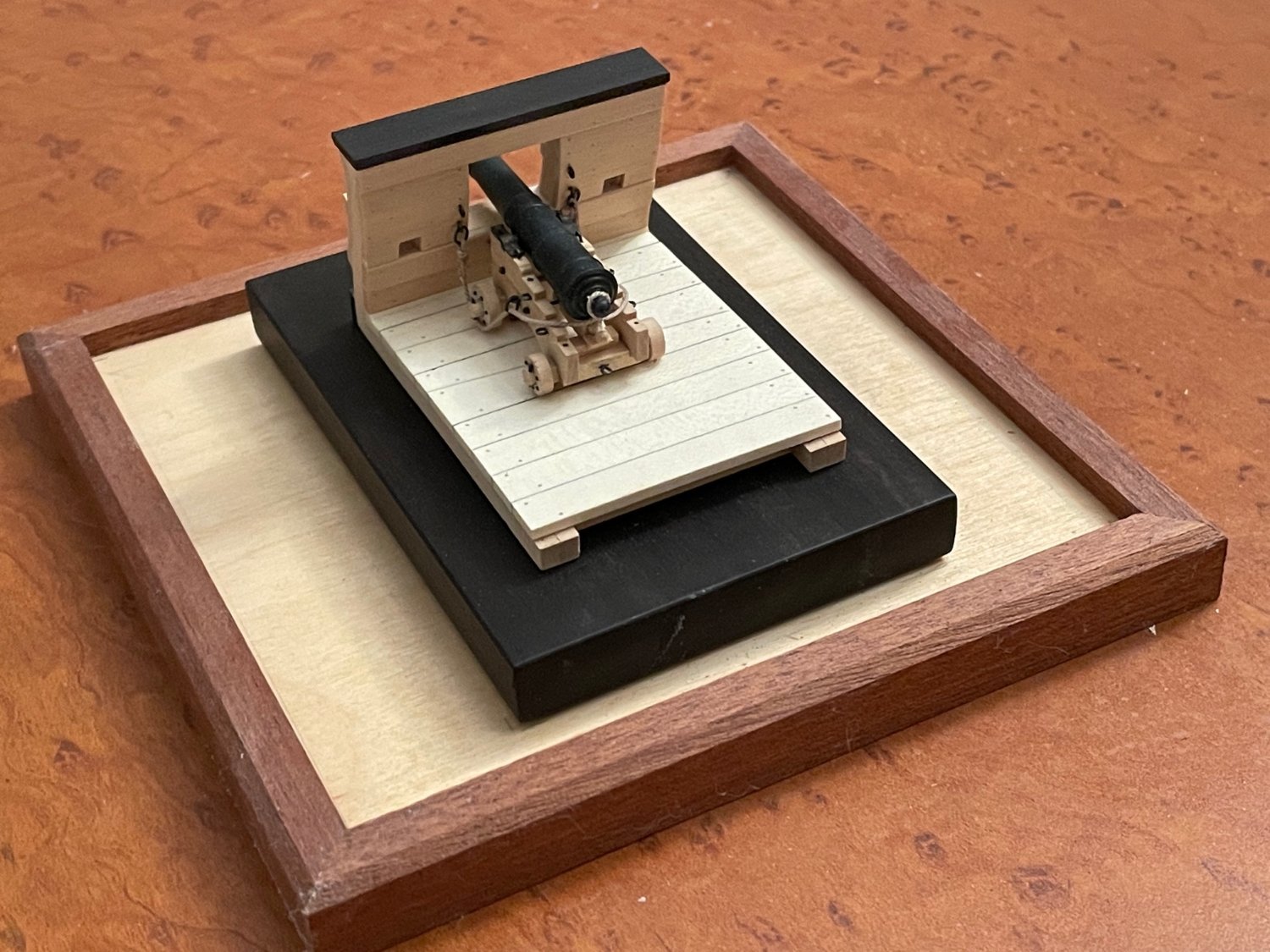
You obviously have mad modelling skills. If you were to turn a cannon barrel to fit the carriage you could alternate between the ship-in-bottle and and scale mini diorama.

- 177 replies
-
- 2
-
-
- Independence
- bottle
- (and 1 more)
-
Good luck with your You Tube build. Perhaps you're familiar with it but if not there is a Trumpeter build on YouTube by the Midwest Modeler https://www.youtube.com/playlist?list=PLdPY23NZym_sO8c4E9Ma0UrCye7yq8BYF. It's very comprehensive and covers all the possible after market fittings as well.
-
I’m not very familiar with ship construction of this period but your work reminds me of all those beautiful builders models in the finest museums. It is a pleasure to watch your build!
-
Must of missed this build. What a clever way to do a ship in a bottle! If you have a barrel you could make it a dual display.
- 177 replies
-
- 3
-
-

-
- Independence
- bottle
- (and 1 more)
-
Stepping the mast with a plum bob...two questions.
dvm27 replied to HardeeHarHar's topic in Masting, rigging and sails
At the risk of sounding hieratical I would suggest not gluing the mast to the step. If, for some reason the ship is ever rerigged or part of the mast breaks, being able to remove it makes this very easy. As an example look at Olha's conservation of the HMS Boreas (YouTube). Assuming the foot of the mast is fitted loosely into some sort of step the standing rigging will keep the masts perfectly positioned once the laniards are reeved and tensioned. An additional advantage is that some adjustments are still possible in the mast position if warpage occurs in the months it takes to complete the rigging process. -
This is a beautiful and unique interpretation of a ship model that has been constructed by many others. It’s a pleasure’s to follow your log.
-
Very nice job on those ratlines. I often see them too large when compared to the shrouds but yours look very much to scale. I found that tying every fifth row, then filling in the spaces between, keeps them correctly tensioned all the way up.
-
I look foreword to your build John. It's been awhile since I've seen one of these solid hull models taken to completion. Personally, I think they are more difficult than plank on bulkhead models. I assume the hull is pine? hard to tell from the photo.
- 165 replies
-
- 1
-
-
- Red Jacket
- Marine Model Company
- (and 2 more)
-
Looking at your work reminds me of the Christmas train gardens I visited in my youth. They inspired me with their complexity and attention to detail. Yet, at the same time, they discouraged me as they set a bar so high I knew I could never match it. I have seen a few videos you posted on your website. You would be doing a great service to the ship model making community if you could find a way to video your splicing technique. Your photos are helpful but a video would fill in the gaps.
-
That's a very well thought out method of producing that tricky upper molding Chuck. Such a beautiful model!
-
Randy, this is a lovely build and deserving of a log. You don't have to post any more than you want. It really is easy and when you have milling questions we'll be able to better help later in your own log.
- 3,618 replies
-
- 8
-
-
- young america
- clipper
- (and 1 more)
-
Are yo perhaps referring to the scupper holes Frank?
- 840 replies
-
- 2
-
-
- winchelsea
- Syren Ship Model Company
- (and 1 more)
-
It might be helpful to know if the $2300 includes the cost of the carvings Chuck. These amazing pieces, alone, have to be quite costly!
-
If you've ever been to La Musee de la Marine there are enormous fully riffed models from floor to ceiling. It was one of the most fabulous maritime museums I've ever been to. I wonder if Wefalck has any knowledge regarding the plans for the new museum? Hopefully they will keep most of the ship models on display.
-
Is there anything more satisfying than when you make those last few passes with sandpaper to fair the hull? Beautiful work Mike!
-
Aren't you the guy in the Tommy Bahama ads?
-
For someone who doesn't like painting you're damned good at it! I've not seen the floral-like GR monogram before on the stern counter before. interesting.
-
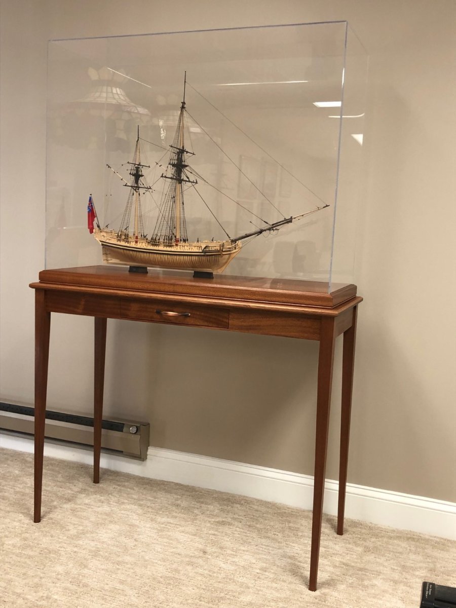
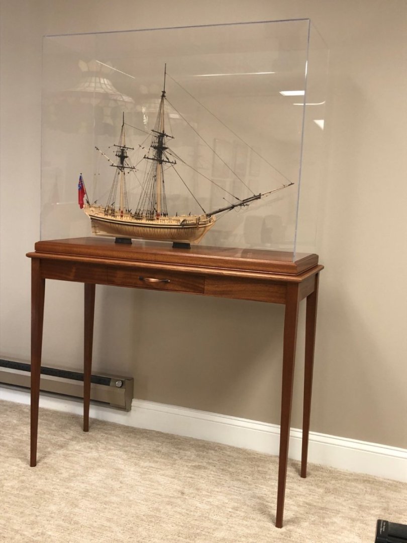
One last Speedwell photo to finish this log. It is now encased in a display designed and built by my son whose hobby is woodworking. He built it out of Sapele mahogany and I think it compliments the model beautifully. Question - can anyone suggest a tasteful, non-intrusive method to light up the model? Whatever it is will need to rest on the acrylic top.
- 345 replies
-
- 33
-
-

-
-
Congratulations Marsalv on a well deserved medal. Is there a link to this exhibition to observe the many other fine models in see in your photo?
- 589 replies
-
- 3
-
-
- le gros ventre
- cargo
- (and 1 more)