HOLIDAY DONATION DRIVE - SUPPORT MSW - DO YOUR PART TO KEEP THIS GREAT FORUM GOING! (Only 20 donations so far - C'mon guys!)
×


dvm27
-
Posts
2,457 -
Joined
-
Last visited
Content Type
Profiles
Forums
Gallery
Events
Everything posted by dvm27
-
 Lovely work Chuck. Seems like those frames take forever but you can turn out 2-3 a day once you get in the groove. Obviously more labor intensive than a POB model but for those who wish to make a POF model Chuck's methods are about as foolproof as it gets. Getting a perfect line of sweep and port sills has always proved difficult for me but Chuck seems to have solved this problem. For the inside of the frames some may wish to invest in an oscillating spindle sander. It makes quick work of these difficult curves.
 -
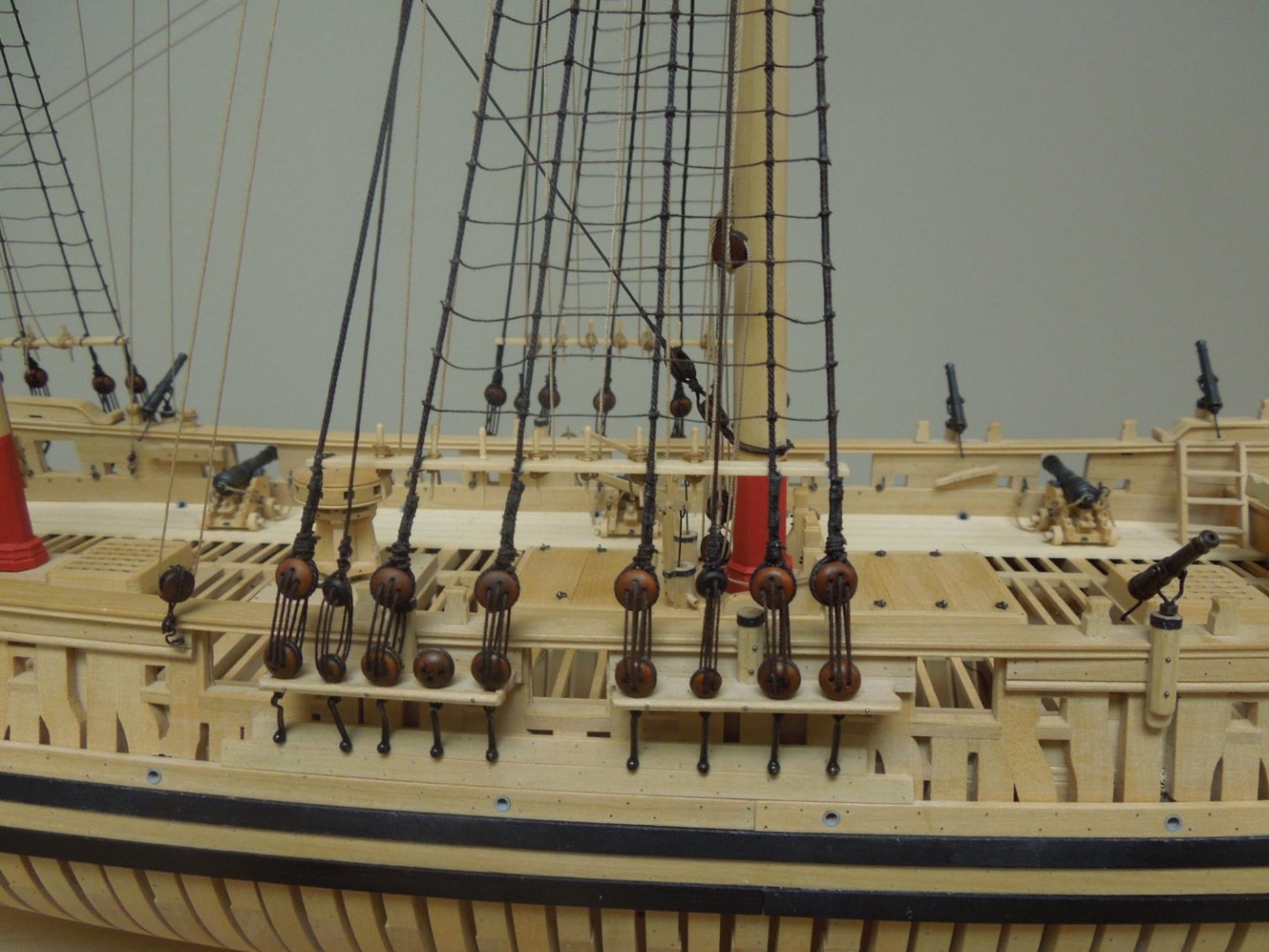
Nice job on those deadeyes. I use a similar jig but cut the wire on the side about halfway down. This is a good time to learn silver soldering if you are not already doing this. It makes for a very tidy deadeye.
-
Photocopying works out if you have one foot X and Y axis's printed on the part to be copied. Most copy stores machines allow you to adjust the X and Y axis's for slight adjustments and usually don't charge for the trial and error of slight adjustments. Just curious - how are you measuring the heights inside the hull for the clamps, hooks etc.? Are you using a height gauge or measuring up from the inner surface of the rising wood?
-
Don't forget that when you level your toptimber line use a long sanding stick with 120 grit on one side and 180 on the other. Sand both toptimber lines athwartships at the same time and creep up on the lines. This way both the height and angle of the toptimbers will be correct.
-
Wonderful update, Marc. Looking forward to many more this year from you. Best wishes for a happy and healthy New Year.
- 2,696 replies
-
- 4
-

-

-
- heller
- soleil royal
- (and 9 more)
-
I had the same problem with my first POF model. Nobody will notice the thinned sections but they will notice bumps and protrusions. For final fairing use pencil marks across the hull. Sand, mark, sand etc. until all pencil marks are gone. Whatever is leftover is your perfectly faired hull. On your next model you'll be less inclined to cut exactly to the frame marks, perhaps leaving 1/16" for those inevitable frame raising errors. Happy Holidays and congratulations on an excellent first POF model.
-
I'd like to show you how we make snowballs in Baltimore, Kevin! Have a Happy Holiday season and looking forward to more excellent updates this year.
-
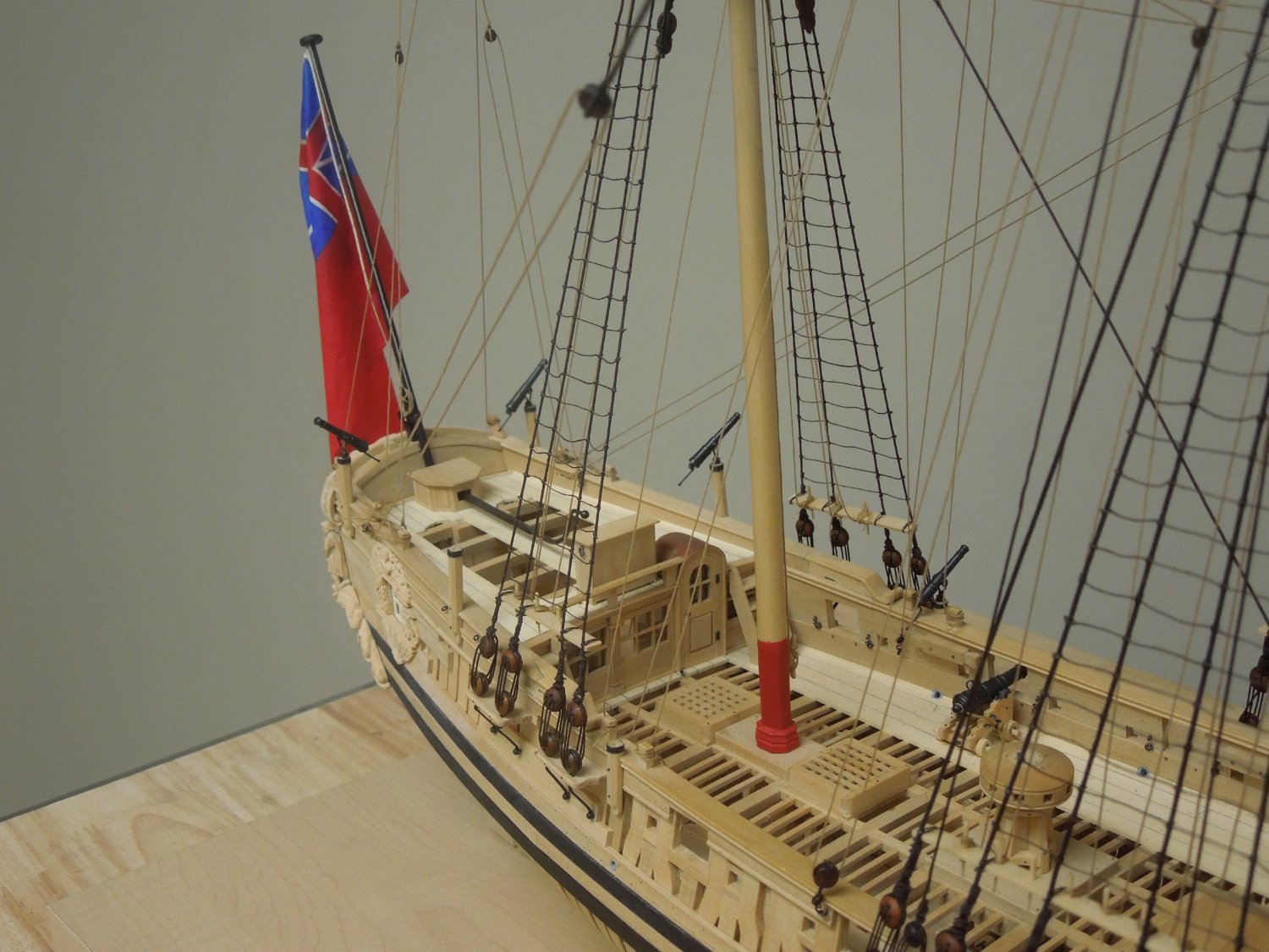
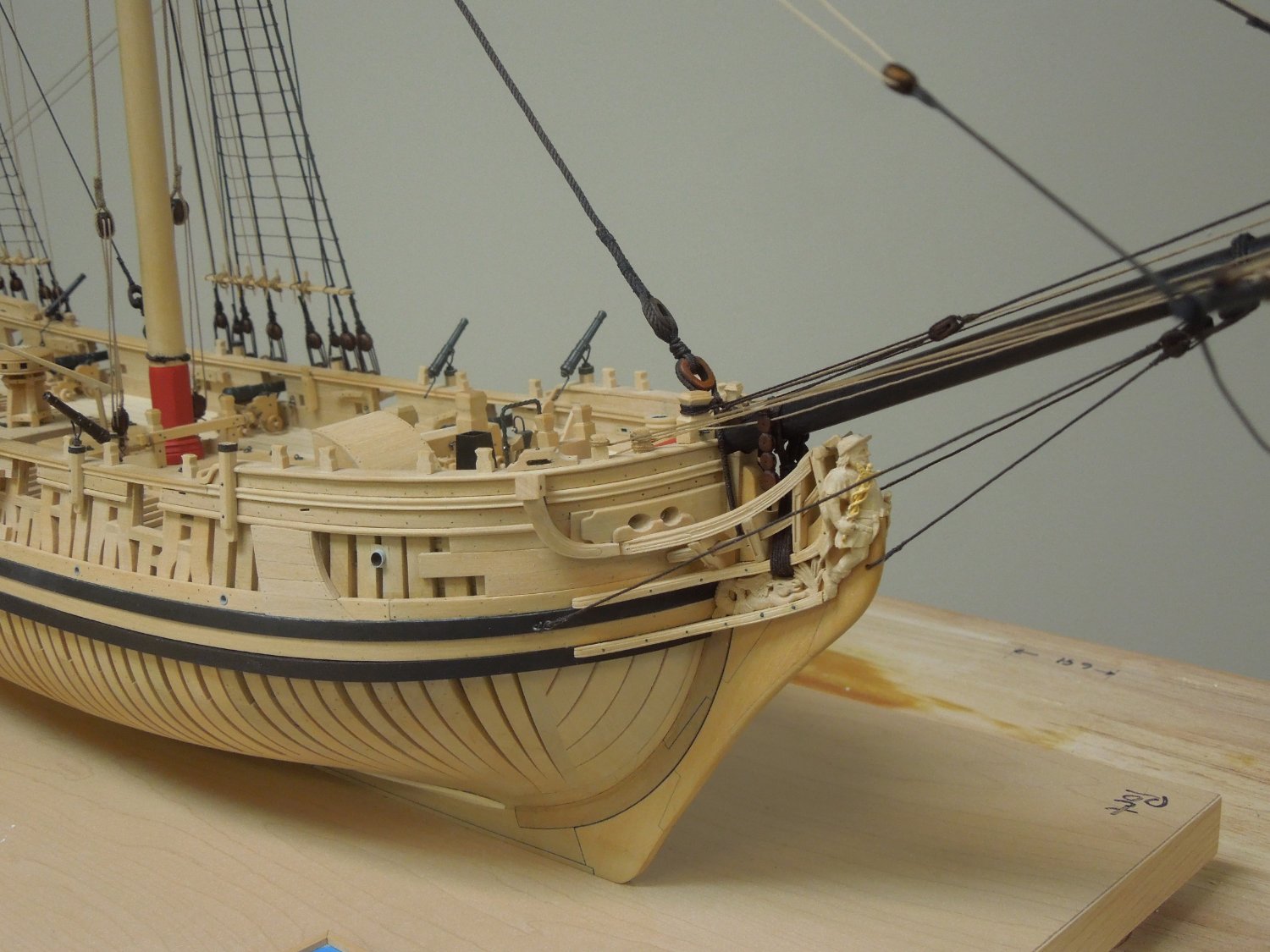
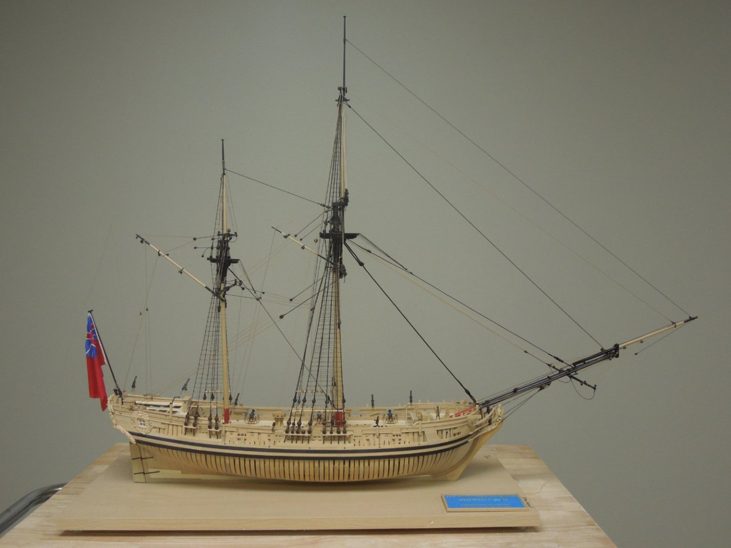
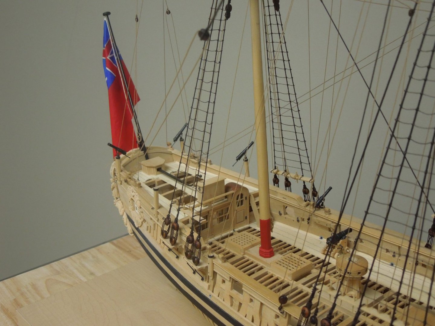
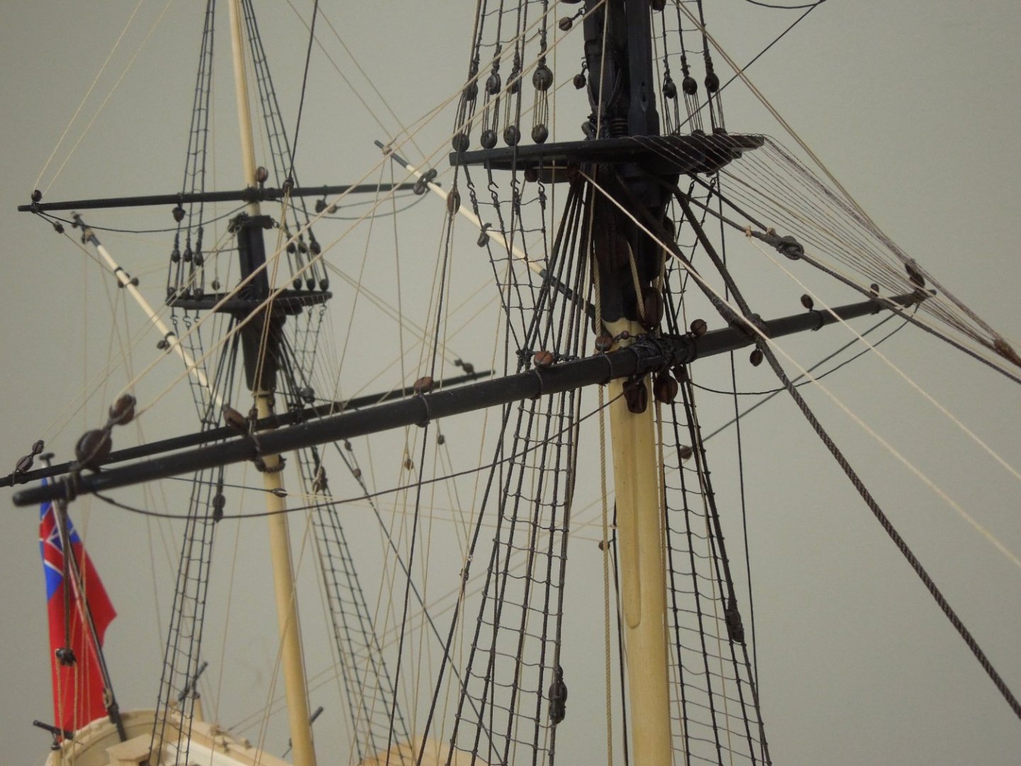
Well gang, Speedwell is finished except for installing the anchors and adding coils over all the belayed ropes. It has been a seven-year collaboration with David Antscherl and I think the finished model has beautiful lines. She has just enough rigging to make it interesting without the repetition of a full ship rigged setup. Thanks to Chuck for his excellent blocks and rope which really dress up the model. All blocks for sails are included even though they are not present. Thanks to all who have commented on her build over the years and I'll be back in the fall with, hopefully, a new project.


- 345 replies
-
- 52
-
-
-

-
With those tiny milling bits I often use them to make a series of small overlapping holes then make shallow passes to clear out the remaining wood between the holes. Might be hard to do in a drill press but the Sherline Mill makes it a breeze.
-
Wonderful work Ben. The slight modification to the carvings makes a huge difference. It's the little details that matter. The carved letters are amazingly well executed. But they look out of place to me. Just a personal opinion but I prefer the flush painted letters, especially if you are painting the outer upper counter and lower counter motifs as suggested by the back cover of Volume II. Others will, I'm sure, favor the current version.
-
Brig Le FAVORI 1806 by KORTES - 1:55
dvm27 replied to KORTES's topic in - Build logs for subjects built 1801 - 1850
You should see my junk box! Your work is stunning Kortes. Nobody gets perfect results every time but persistence pays off. -
Congratulations on the completion of your beautiful ship model Ian. It compares very favorably to David’s model and that’s high praise indeed.
-
The ships of the Cruizer class, of which Speedwell was one, were built in 1752-1754 to address the prevailing French and Austrian Wars. The Admiralty wanted fast, shallow draught ships that could carry out policing operations in the Channel and Foreland Stations and discourage French privateers and smugglers. Therefore, a variety of hull design and rig combinations was employed by the Admiralty to see which best fulfilled these requirements. Some were ketch rigged (Speedwell, Fly, Happy and Ranger) while others were snow rigged (Wolf and Cruiser). All this experimentation eventually led to a refinement wherein Cruiser was given a mizzen mast (1753) and ship rigged. This proved to be so successful that the ketch rigged sloops fell out of favor as the ship rigged sloop became prevalent. With the advent of the brig-of-war later in the century the snow rig once again gained popularity. (From Building Plank on Frame Ship Models, Ron McCarthy. Naval Institute Press)
-
Hole size is proportional to block size so if you're having trouble perhaps the blocks are too small or, more likely, the rope is too big. In any case for rigging one must have a set of miniature reamers such as: https://www.amazon.com/Model-Craft-PBR2194-Cutting-0-6-2-0mm/dp/B001JJZ76I/ref=asc_df_B001JJZ76I/?tag=hyprod-20&linkCode=df0&hvadid=598232118681&hvpos=&hvnetw=g&hvrand=1012005693499827230&hvpone=&hvptwo=&hvqmt=&hvdev=c&hvdvcmdl=&hvlocint=&hvlocphy=1018605&hvtargid=pla-422910410143&psc=1 As well, using CA on the final 1/2" of the line and pointing it after dry will allow you to get the rope started as James has stated above.
-
Rest in peace Bob. Your log updates were always a highlight of my day.
-
Love the stippled detail on the bitts!
-
That's as fine a model as ever came out of the famous ship builders model workshops in the mid-1900s. We hope you will take many close up photos when finished.
-
I would have never thought one could design a foolproof method of plank on frame construction but you seem to be on track to accomplish this Chuck. Your framing plan also insures that the sweep and gun ports will be in perfect alignment, always a difficult task. And yes, it is a pleasure to build without elaborate upright building boards. You can actually appreciate the fine lines of the hull as they are formed.
-
You should try a mock up rudder in the space. For some reason none of the rudders on my models will go through the full range of movement because my openings are too small.
-
After the previous post I was wondering of you could make that incredibly complex taffrail rail to match. I have my answer. Brilliant work Ben!
-
Well I wondered how you were going to approach those difficult apron and (presumably) stern deadwood steps. That is a brilliant solution and insures those cants will seat at the exact location and angle required. Here's a mind bending thought exercise. If one did not possess a laser cutting machine would your framing method be easier or more difficult than the techniques described in our Speedwell book? I'd have to really ponder that one.
-
Those mortises are very difficult to cut at first. Accurate layout with a height gage is essential. If the joint looks a little sloppy after the sills are installed a little white glue applied over the joint then light sanding will make a perfect joint