


wefalck
-
Posts
6,413 -
Joined
-
Last visited
Content Type
Profiles
Forums
Gallery
Events
Posts posted by wefalck
-
-
I tend to mistrust zu Mondfeld somewhat, as he tried to cover too many periods ... I would also question the statement that only one size of pins was used on any one ship. I can understand the logic, but it also a question of space and materials economy. In addition, and perhaps most importantly, belaying a too thin rope on a too big pin either requires a lot of rounds or it will not be secure. It also take a long time to do.
I have a table of belaying pin dimensions from Middendorf (1903), which I can copy here tomorrow. It would be correct for late 19th to early 20th century and contains metal pins for sure, but I am not certain about wooden pins.
- Keith Black, tkay11, G. Delacroix and 1 other
-
 4
4
-
I don't know, how big the model is, but is there so much sanding to do that you need an electric sander?
There is also the risk that the edges of the sandpaper bite into concave sections of the hull.
Sanding blocks and sanding foam-blocks might be a safer option.
- Highlander and mtaylor
-
2
-
I think, I would plank the transom after fitting it into place, although it would be easier to clamp down the planking when it is lying flat.
On the topic of building-jig: yes, I suppose a jig would make the aligning of the bulkheads easier, as one can makr out their position on the board. I think a simple board would be sufficient on which you can clamp the backbone upside-down to facilitate planking.
Boatbuilders strech a string from the bow to the transom and use a stick to measure symmetry of the frames or of the planking, when it is a clinker-build.
- Keith Black and JacquesCousteau
-
1
-
 1
1
-
Very nice model indeed and a subject not often, perhaps even for the first time, seen here ...
If you happen to be in London, you may want to visit the London Canal Museum: https://www.arbeitskreis-historischer-schiffbau.de/mitglieder/ontour/london-canal-museum/. This page is in German, but you can have it easily translated these days.
Outside the museum, which is an old ice-house, there is a harbour basin (Battlebridge Basin), in which during winter-time dozens of narrow-boats are laid up.
-
I couldn't check against my photographs, but the chain-plates look rather on the thin side to me.
- Keith Black, Dart and Harvey Golden
-
3
-
... keep in mind that Javier (who is also here on MSW) mostly works in 1/150 to 1/200 scale and his creations are only a few centimeters long.
I think I suggested earlier also to fill the spaces between the bulkheads, which makes fairing and planking easier.
- mtaylor and Keith Black
-
2
-
First of gratulations to this nice model and the gold medal!
Concerning figures: 1/144 seems to be a common aircraft model scale. The German manufacturer Preiser (probably the best on the market for styrene figures) has a small range in that scale: https://www.preiserfiguren.de/download.php?file=PK 28 Seite 308.pdf. There are also numerous offers of 3D-printed military figures, but one would need to look around for another market platform after Shapeway went into bankruptcy last summer.
I believe that the UK model railway N-scale is actually 1/148 rather than 1/160, so poking around British manufacturers might be helpful.
In any case, the figures will need some carving and sculpting to bring them to the right era. This is not too difficult. I have just done this for my S.M.S. WESPE project here in 1/160 scale.
- Keith Black, GeorgeKapas and mtaylor
-
3
-
There are several options:
- you can use your battens and mark off the position of bulkheads equally on both sides; one can do this with a piece of string, the length of which one adjusts iteratively together with the angle of the bulkhead until it is equal on both sides; always measure from the stem; this is perhaps the most precise method without tools.
- you can draw/print the pattern of bulkheads on a piece of paper and, holding it over the framework, you adjust and glue in place the bulkheads one by one.
- use something of which you are sure that it has a right angle and adjust the bulkheads against this.
The boatbuilders of old probably would have used the first method ...
-
I wouldn't know what is available in the USA.
For me, at railway scales the manufacturer to go to is Preiser: https://www.preiserfiguren.de. Preiser has a small range of 1/100 figures, but basically only modern pedestrians for architectural models.
There a dozens of manufacturers for military figures in styrene, casting resin, and white metal. I am not familiar with the current market in that respect.
There are also numerous offers for 3D-printed figures on the respective platforms, mainly in the military and aircraft scales. Many of these figures seem to be of good animation and detailing, but the printing quality may vary. Sometimes they are scaleable and you can specify the scale you want.
Another route are service providers of files for 3D-printing, which can be customised in sometimes quite sophisticated way, say with respect tot he animation and clothing. The problem is that they seem to mainly aim at the 'gaming' community, where there seems to be a fashion of gnome-like appearance. The latter is also a problem with many of the 1/72 scale figures that are available commercially (see https://www.plasticsoldierreview.com).
-
Yes, I would think that this would be a typical job for photoetching.
I would actually give it to my laser-cutter to chew ... and then build up the body with acrylic gel, followed by some gilding.
There are also these '3D-printing sticks', sort of hand-held extruders with which one can build-up such patterns.
- Keith Black, yvesvidal, KeithAug and 1 other
-
4
-
However, if you cut the grating from a single sheet of wood, the grain will run into the wrong direction for one set of battens.
One could improve on this by cutting the notches prototype fashion and then the matching battens from a sheet of wood with half the thickness only.
- Gregory, thibaultron and mtaylor
-
3
-
The biggest market is that for model railways and there are a lot of offers in 1/76, 1/87, 1/120, 1/160, and 1/220. Or the military scales of 1/32, 1/48, and 1/72. 1/144 seems to be popular with aircraft modellers.
Ship model tend to be built in the scales in which the old drew their plans: 1/96 (1/100), 1/48 (1/50), or larger.
I chose railway scales for my projects to have access to the respective ranges of figures.
- oudi2311, Keith Black and mtaylor
-
3
-
There are a couple of reasons: there are figures available at N-scale - it's small, which is important, when you don't have a lot of space for large models - and it is challenge to try to put as much detail into it, as one typically would put into something twice or three times the scale 😉
1/150 to 1/160 scale is still big enough so that one can find suitably thin materials for representation in scale.
- Keith Black, ccoyle, cotrecerf and 5 others
-
8
-
Thanks for your interest and comments!
@Dr PR One has to keep in mind that the hull will be only about 150 mm in total and the planks will be a maximum of 1.5 mm wide and around the bulwark only 1 mm (= 160 mm on the prototype. I have been thinking about marking the planks on the bulkheads, but with the close tolerances needed, that may not be possible. I started marking out the whale, but that has to be improved still, as the tapering is not yet considered. Tapering the planks at that size will be a challenge. I may calculate the width from the CAD and then make a print-out on paper and try to shape the planks to this paper template. I will have to build a jig to hold the 1.5 mm wide and 0.25 mm thick strips of styrene to be used for planking while trying to taper them.
@BANYAN Most people here, of course, would use wood, but at 1/160 scale, covering-up all the wood-grain is a lot of work. It would be completely out of scale. Also, for me it is difficult to obtain and mill hardwood, such as boxwood. Living in a city apartment imposes certain restrictions. As the whole model will be painted, as ships of that time usually were, it doesn't really matter what is underneath. Acrylic glass (particularly the cast variety of PLEXIGLAS®) is an excellent material for machining and can hold very sharp edges, which is needed at this small scale. I still have a good stock, as my father used to work for a subsidiary of the manufacturers of PLEXIGLAS and we got the stuff for little money back then.
- mtaylor, FriedClams, rcweir and 8 others
-
11
-
Just to keep the ball rolling
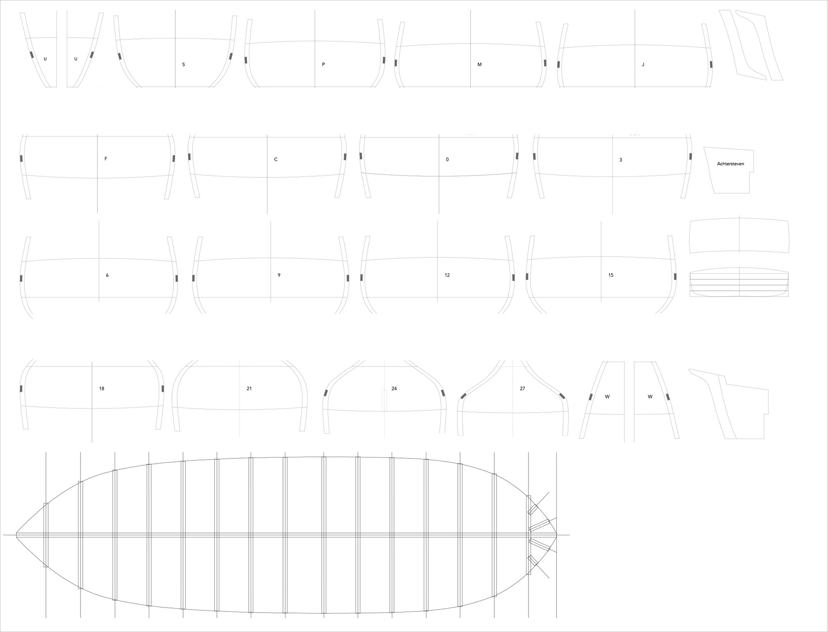
It is not that nothing happened in the background in spite of various travels and work to earn money …
Much time was spent interpreting the original drawings and to prepare drawings for the actual building process. Luckily the spacing of the frames in the body-plan was such that it equalled the spacing of three frames of the prototype and every third frame would have been elongated to serve as bulwark stanchion. This saved a lot of real lofting, as the bulkheads just had to be copied and the missing details and reference lines needed to be added.
However, cant-frames were not drawn and had to be lofted from the lines- and body-plans. The same for the longitudinal frames that support the transom and the gilling.
As this will be a waterline model, the hull will be constructed on a base-plate. The base-plate will be 4 mm Plexiglas into which 1 mm deep slots for the bulkheads and the stem- and sternpost pieces.

The size of the drawing 190 mm wide and 145 mm high
The drawings will be stuck to 1 mm acrylic glass and sawn out.
To be continued
- rybakov, druxey, Keith Black and 10 others
-
13
-
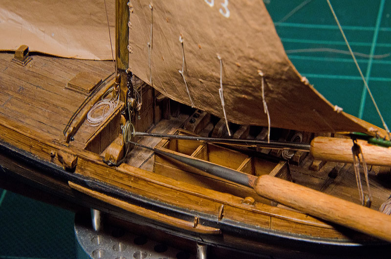
Yep, the crew brings to life this quite unusual project 👍🏻
- FriedClams, Keith Black, mbp521 and 2 others
-
4
-
1
-
I don't have a picture to hand, but there seem to be ways of rigging, where the parrel has an eye spliced in the end and the rope goes around the mast, the yard then down through its own eye. In this way it can be hauled close or loosened from the deck.
- mtaylor, JacquesCousteau, FriedClams and 1 other
-
4
-
They could even pose a danger, when blown away partly, as they could catch any crew on deck and sling-shot them overboard.
In a storm, one would tie-down and furl everything that is not really needed in order to reduce wind resistance. Only small sails, if any, were set to keep the steering in the ship. An awning would have had the effect of turning the ship into the wind in a rather uncontrolled fashion.
-
Not sure, it would work at this scale, but I coerce ropes into a 'natural' shape by wetting them with a fast-drying varnish and holding them down until the solvent has evaporated:
-
I make my tissue-sails on a board covered tightly with cling-film. Paints and glues faintly stick on it and it can be peeled off instead of peeling the sail off, if needed.
- FriedClams, Glen McGuire, Paul Le Wol and 3 others
-
5
-
1
-
Apart from John's comment, it also depends on what you really want to do with it.
Wooden battens indeed follow a natural curve of the hull and would be the tool to go to, when your planking scheme is unconstrained.
On the other hand, if you want to reproduce the planking scheme of a historical prototype or model, you may have to divide the circumference of the frame into the correct number of planks and this will determine their run, width and shape. These can be taken off with strips of transparent paper and transferred to the plank.
BTW, the main constrain on planking schemes are the wales and rails (and of course the keel, as well as stem- and stern-post), which are given by the historic design. So the planking has to fall in between these.
-
That would be the main use, really. You take off the circumference of a frame e.g. with a narrow strip of paper, then you set the dividers to the number of planks you need, take with the long end the total length and, voilà you got the width of the planks at the short end. You then can transfer this to the hull directly or mark it on the paper strip.
Beware, this is in fact a chain-measurement and any individual error at each marking off adds up. Normally, in engineering this is avoided. That is why I would do this on a computer and print out the strips for each frame.
- Ryland Craze, GGibson and mtaylor
-
2
-
1
-
It probably depends also on the size of model one is working on and on the size of the proportional dividers. I found mine just too unwieldy for my small models.
If you insist on the proportional dividers, you also divide the paper strips with them - you have to use the paper strip anyway to measure the total circumference of the frame.
-
I think in this case the thickness of planking is important, at least not as long as you can't see it on the finished boat, because this will be a rendering of a type of boat, rather than a specific one. The size of the lanchas may have varied a bit depending on the preference of the owner and the availability of material.
On the other hand, plank thickness is important for determining how much much the stem and keel pieces have to protrude beyond the bulkheads. As the original plan was for a model, one needs to know for what plank thickness the bulkheads were calculated.
Working with thinner planks has two advantages: bending is easier and the edges of the planks need to be bevelled less in order to achieve a close fit between adjacent planks.
- mtaylor, JacquesCousteau, Paul Le Wol and 2 others
-
4
-
1
How will laser cutters compliment our hobby tomorrow?
in 3D-Printing and Laser-Cutting.
Posted
Well, it's the old discussion of machine work vs. hand work ... there are people cutting their own files and saws and making their own drills to replicate ancient manufacturing process in e.g. watchmaking ...
I got into laser-cutting with a simple and small machine for making intricate small parts, because it is less messy than photo-etching and because it can be used 'ad hoc', i.e. I can make parts, when I need them. Cutting larger pieces of wood requires a lot of supporting infrastructure, such as extraction fans or even water cooling, which makes their use difficult, unless you live in your own house.
3D-MLA-printing will be the future I think. However, it also requires considerable supporting infrastructure, as you need to have a workbench, where you can mess around with the resin, for cleaning the printer and the parts and for post-processing (UV-curing). So there are limitations depending on your personal circumstances.
The question is, whether you want the best possible result, no matter what means, or whether you want to show off your craftmanship.