druxey
-
Posts
13,356 -
Joined
-
Last visited
Content Type
Profiles
Forums
Gallery
Events
Everything posted by druxey
-

Framing around a gun port
druxey replied to Don Case's topic in Building, Framing, Planking and plating a ships hull and deck
Just to clarify the above: the two 'slices' together make up a frame pair. However, in some cases (this will drive you crazy) the slices were separated by small chocks to allow more air circulation. -
Tell Me Why This Is A Bad Idea ( If it is )
druxey replied to Gregory's topic in Modeling tools and Workshop Equipment
If your brain even suggests 'Is this a bad idea?', then chances are, that it is! Use inserts for peace of mind, accuracy and bodily integrity. -
You are figuring it out fine, Bob.
- 52 replies
-
- 1
-

-
- Model Shipways
- muscongus bay lobster smack
- (and 1 more)
-
Framing around a gun port
druxey replied to Don Case's topic in Building, Framing, Planking and plating a ships hull and deck
Don: the math of room and space is (in your quoted example) 12" plus 12" (a floor + a first futtock) which is 24". This leaves a mere 2" of space to make the 26" of R & S. As Allan suggests, you really need to read up on all this to understand the construction of a wooden vessel. The one exception will be at the dead flat frame. This was either single or triple (occasionally even quintuple). It was always an odd number so that the floor changed sides on the frame pairs at that point along the hull. There is so much more to the business of framing, as I hope you will discover. -
It's quite possible. Eberhard; but at this scale it will make life a little easier to have a two-piece strake. Bruce: It's Castello boxwood.
- 433 replies
-
- 5
-

-
-
- open boat
- small boat
- (and 1 more)
-
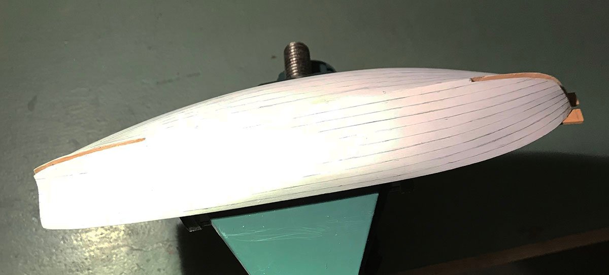
Small update: The transom proved trickier than it first appeared. It has a slight but distinct bow to it. I first thought that I could bend this, but the thin (1 mm) stock warped in the vertical direction as well. I was forced to cut the transom out on the curve. This was carefully done using a fine blade on the scroll saw. It was then lightly sanded, trimmed oversize and glued to the stern post. Next was to mark out the shift of planking butts. Using my five frames, I was able to make a four strake shift work nicely. (The marks are to one side of the frames, but the planks will butt on them.) This completes preliminary work. Next will be to remove the frames, wax the plug and re-inset them. The spine assembly will them be mounted ready to fair the transom to the plug and begin the planking process.
- 433 replies
-
- 16
-
-
- open boat
- small boat
- (and 1 more)
-
Framing around a gun port
druxey replied to Don Case's topic in Building, Framing, Planking and plating a ships hull and deck
Sorry, Don, but in English shipbuilding what you show was simply never done. The timber on each side of the port needed to be strong, as the bolts of the breechings - which absorbed recoil of the guns - and training tackle were attached through them. Therefore maximum strength was required of these timbers. Your version would give way at the first shot. Study contemporary framing diagrams such as the one Allan has posted carefully to begin to understand actual framing practice. There's lots to learn, trust me! -
So, based on previous experience, I shall remove the formed frames and wax the grooves as well as the rest of the plug before gluing the frame extensions to the blocks. This will, I hope, prevent any from detaching from the planking later. As you can see, the frames are merely clipped in place at present. The frame stock was first soaked in hot water, then bent in place using controlled heat from the iron I use for restoration work of easel paintings.

- 433 replies
-
- 16
-
-
- open boat
- small boat
- (and 1 more)
-
Thanks for looking in, everyone. Eberhard: in this particular boat, neither keel nor keelson are scored for the frames. Unfortunately that isn't an option here.
- 433 replies
-
- 3
-
-
- open boat
- small boat
- (and 1 more)
-
Lovely, Siggi. I look forward to seeing those entry steps installed! Just don't mix them up....
-
Thank you, Allan. Certainly fewer pieces are required for horizontal rather than vertical slabs for the plug. Also, as you point out, there is far less end grain to deal with. I had considered redrawing the lines to 'inside of frame' and doing what you show, but as I'm only putting in a few frames and making the slots a loose fit, I decided to be lazy! Different strokes....
- 433 replies
-
- 7
-
-
- open boat
- small boat
- (and 1 more)
-
And, when all else fails, read the instructions!
- 85 replies
-
- 3
-
-

-
- Lowell Grand Banks Dory
- First Build
- (and 2 more)
-
They will be bent in using moisture and controlled heat, Maury. Stay tuned!
- 433 replies
-
- 4
-
-
- open boat
- small boat
- (and 1 more)
-
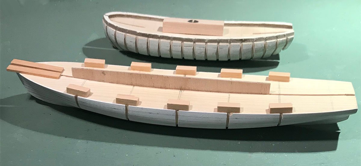
Work on the plug is finally complete. Small blocks have been glued as shown for attaching the temporary extensions of the frames. In an earlier stage of developing this technique, I grooved for every frame (top of photo). This proved to be very labor intensive and, when the model was removed from the plug, resulted in quite a number of frames detaching. I was able to reattach them, but it involved extra work. The current plug will, I hope, work better. Next will be to prepare about 5' 0" (actual) of framing stock. It will be a few days before I post again. Thanks for following this!
- 433 replies
-
- 22
-
-
- open boat
- small boat
- (and 1 more)
-
'No idea' indeed! False and misleading advertising if ever there was. Lovely work.
-
Next was marking out and cutting the grooves for the frames I decided to put in every fourth frame. To assist marking out, I used a piece of thread wedged into two small cuts at the top of the plug. The grooves were sawn and then finished with a narrow pillar file. A piece of stock for the frames was used as a depth gauge.
- 433 replies
-
- 20
-
-
- open boat
- small boat
- (and 1 more)
-
I would be cautious about using CA glue - there's almost no time to adjust things. Much more 'wiggle room' with white or yellow glue.
- 85 replies
-
- 2
-
-
- Lowell Grand Banks Dory
- First Build
- (and 2 more)
-
You are correct in your observation, Bruce. Tumblehome will be there, but if I put it in now I'll not be able to get the model off the plug without damage. There's lots of thinking ahead required with this kind of build! Speaking of thinking ahead, I have to plan the integrity of the shell. If the boat were clinker built, there would be sufficient gluing area to hold things together. In this case, carvel built, the joints between the planks are so small the chances of failure are almost guaranteed. To minimize this possibility, I shall be grooving the plug for several frames so that the planks will also be attached to them as well as each other and the spine assembly.
- 433 replies
-
- 10
-
-
-
- open boat
- small boat
- (and 1 more)
-
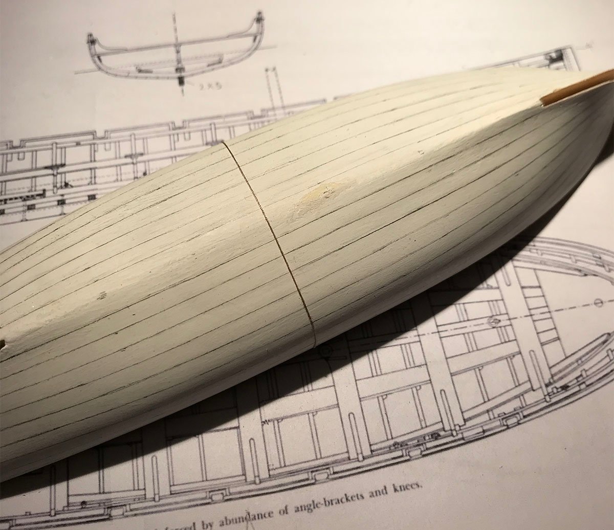
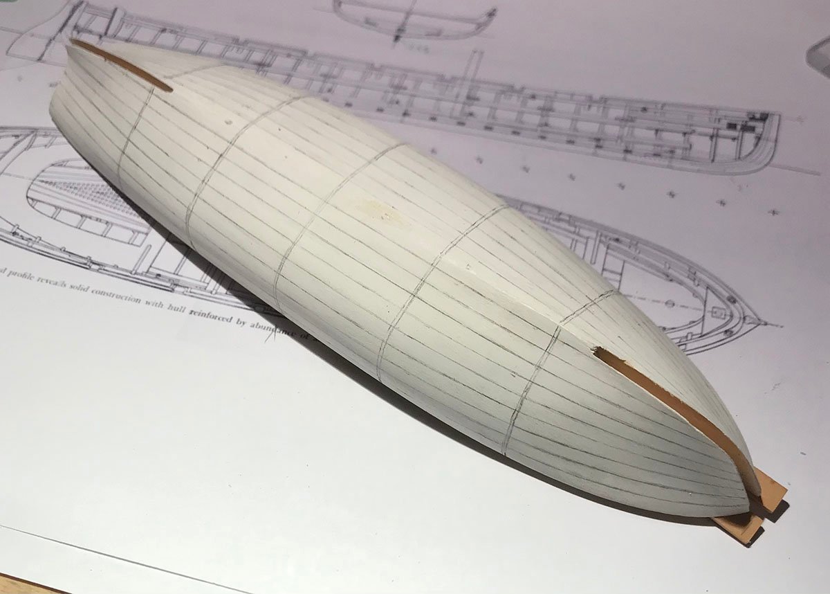
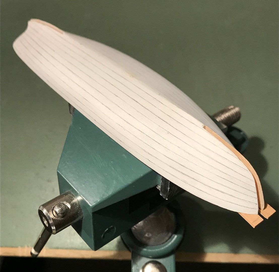
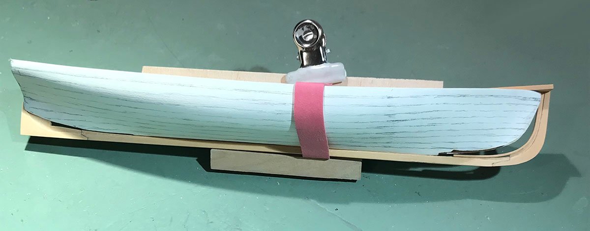
The lining out of the planking has now been refined. Even the thickness of a thin pencil line makes a difference at 1:48! Pencil erases well over gesso. There was much erasure. I use 4H leads in order to get the thinnest lines possible. The beauty - or lack of it - in the final model will depend on precise marking out. The next step in the process will be to mark out the frames on the plug.
- 433 replies
-
- 17
-
-
- open boat
- small boat
- (and 1 more)
-
The gesso is acrylic, not the traditional one. It sands very well, Eberhard. I will still wax the plug before building over it.
- 433 replies
-
- 4
-
-
- open boat
- small boat
- (and 1 more)
-
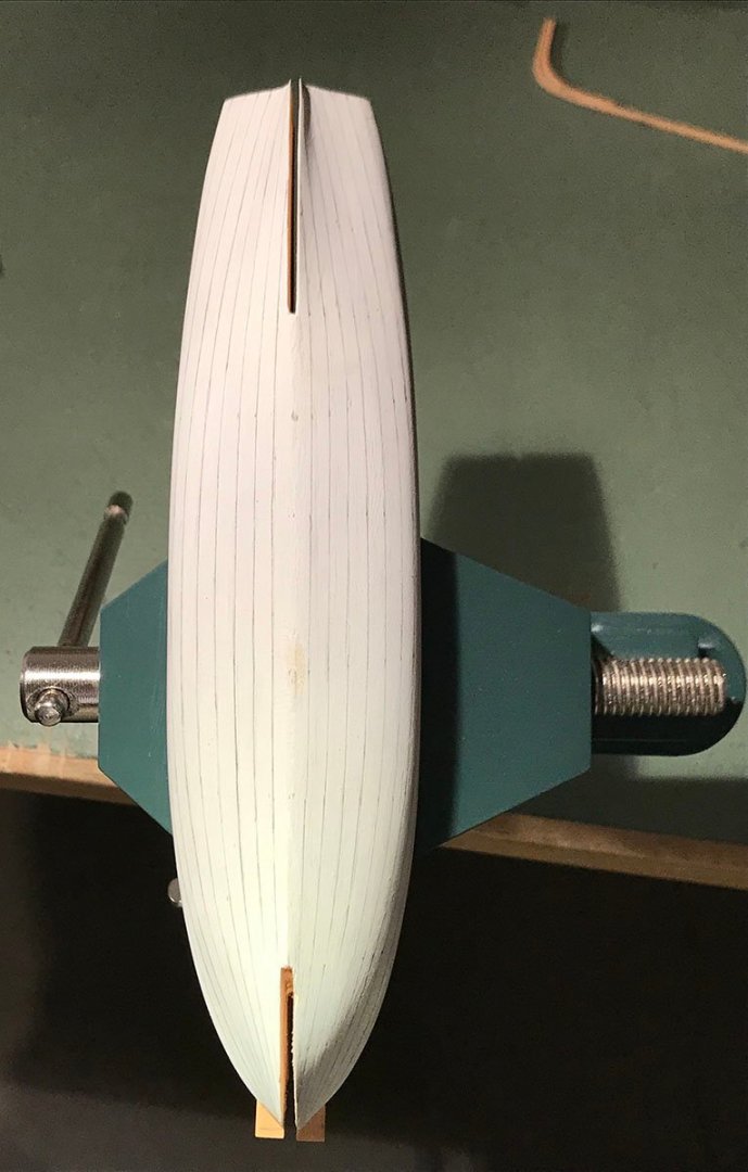
Thank you, Joe. Next was to refine the planking layout. At this scale the width of a pencil line makes a difference! As you can see, it's almost these now. Lining out is a science and an art. If one only scientifically divides the space for the planking, it does not always look fair to the eye. I had to then use a bit of art - and maybe a touch of alchemy - to make the lines run fair to the eye from stem to stern. There will still be some minor adjustments before transferring the mark-out to the second side.
- 433 replies
-
- 24
-
-
-
- open boat
- small boat
- (and 1 more)
-
I agree that a book can suck countless hours into space. One does it for love, not money! (Unless you write fiction on the level of an A. J. Rowling.)
-
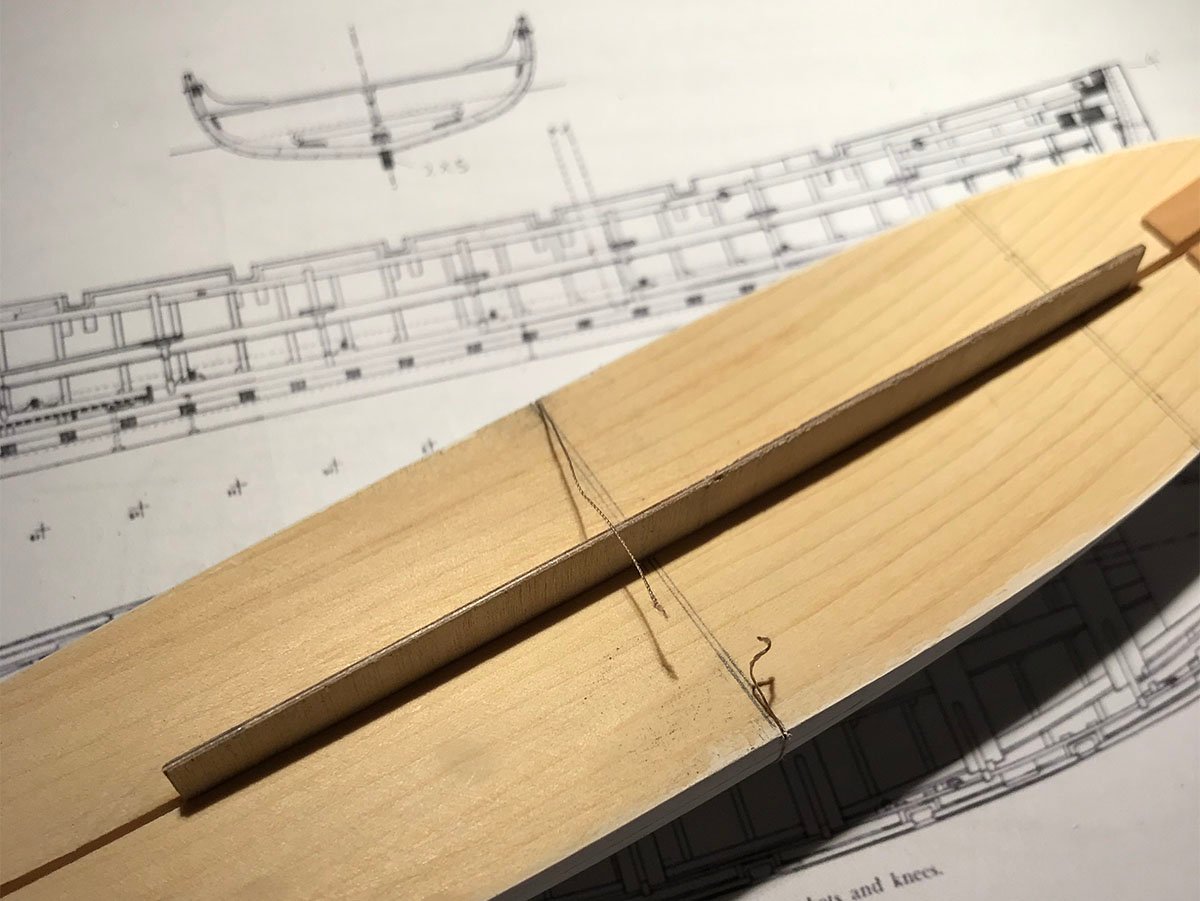
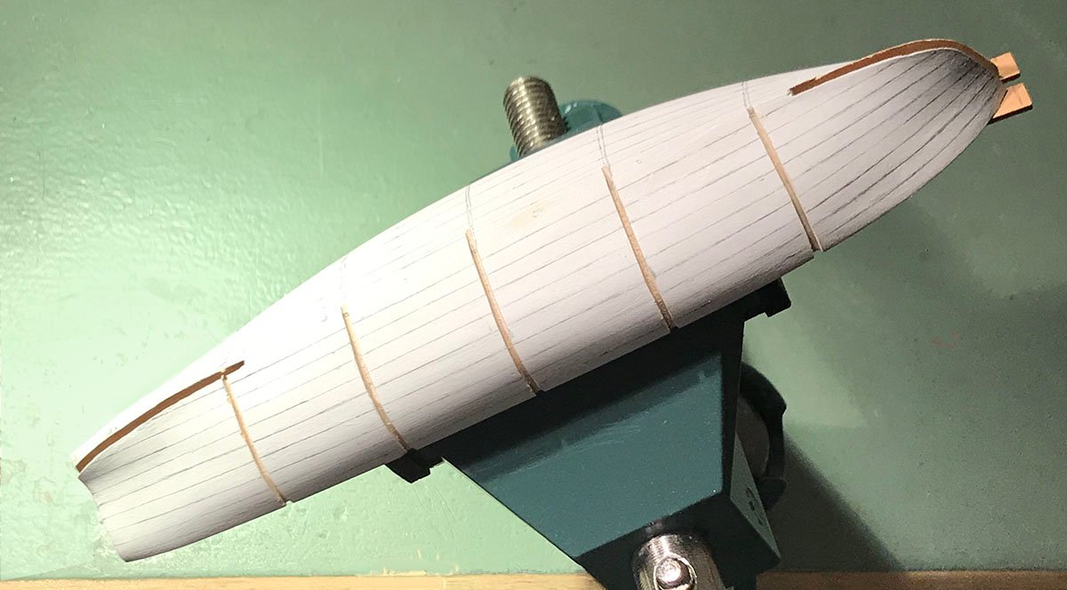
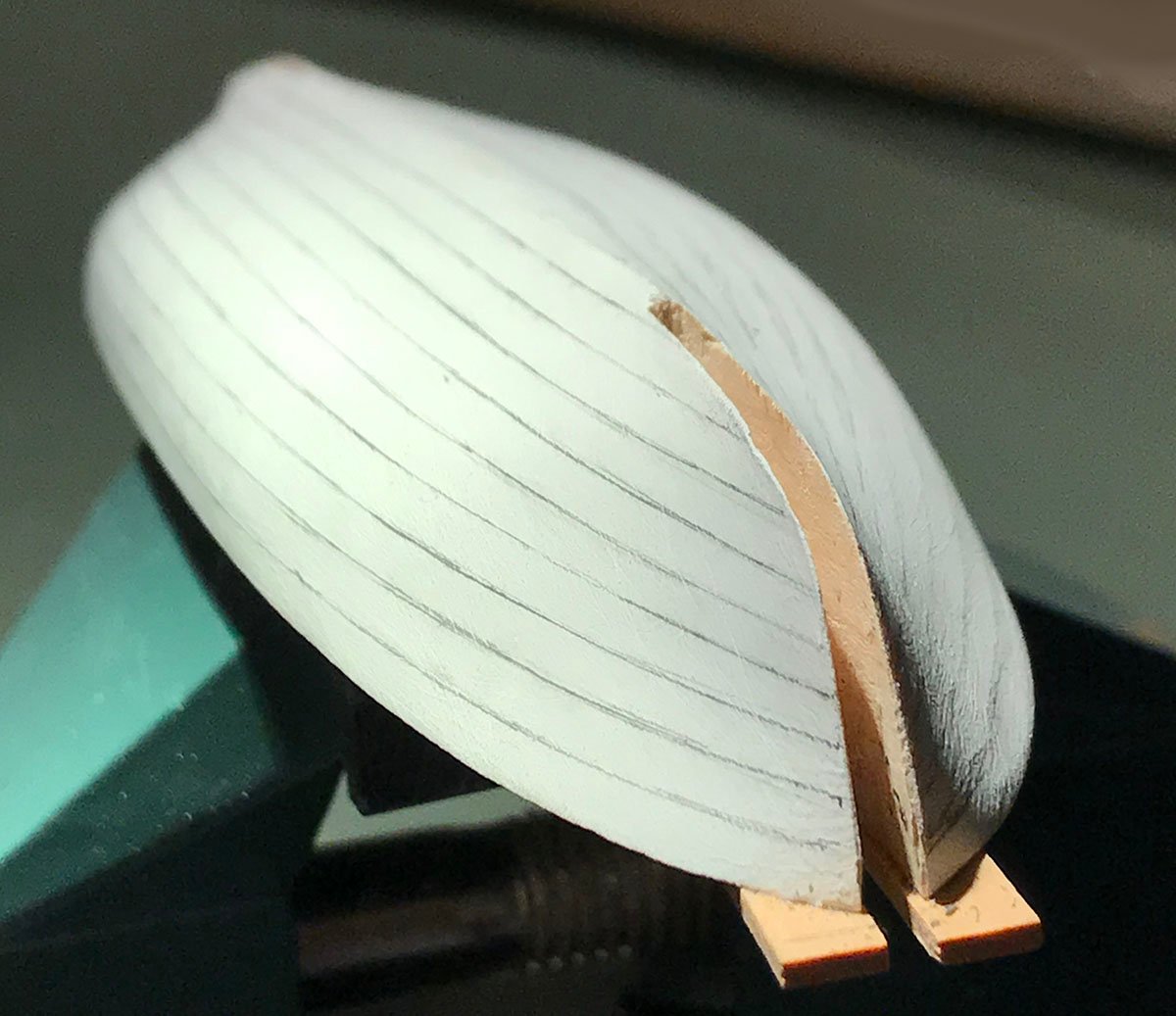
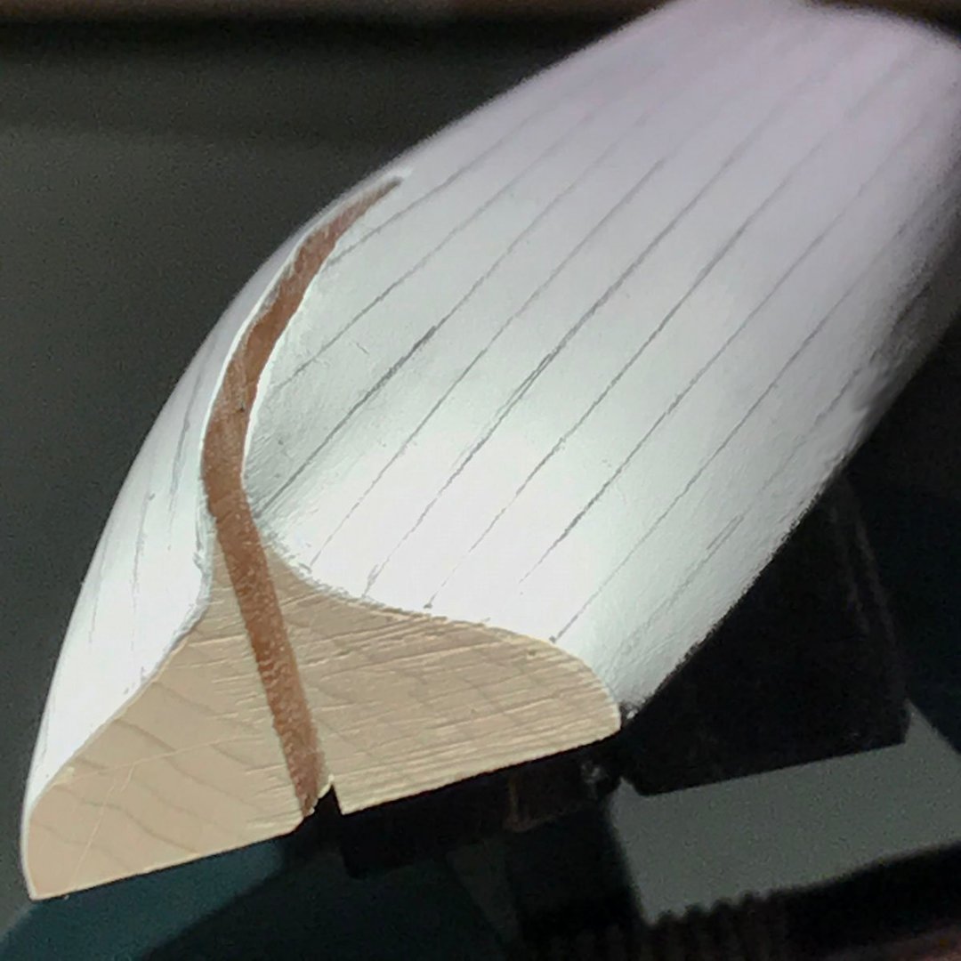
Thanks for dropping in and having an interest in this project! The next step was to fit the backbone and plug so the slots at bow and stern were widened to accommodate them. The run of the planking was next sketched on. Looking at the photos from Venice, it appears that there are ten strakes below the sheer rail. As you can see, the run aft looks quite good already, but the fore body needs correction. The planking will be delineated far more accurately as corrections are made. This comes next. The deliberate gap at the forefoot is that the hull form is so fine here that, if the plug were in the way, the planks will not run smoothly into the stem rabbet.
- 433 replies
-
- 25
-
-
- open boat
- small boat
- (and 1 more)