Dziadeczek
-
Posts
596 -
Joined
-
Last visited
Content Type
Profiles
Forums
Gallery
Events
Everything posted by Dziadeczek
-

Papegojan 1627 by mati - FINISHED - 1/48
Dziadeczek replied to mati's topic in - Build logs for subjects built 1501 - 1750
Thank you, Mati. -
Papegojan 1627 by mati - FINISHED - 1/48
Dziadeczek replied to mati's topic in - Build logs for subjects built 1501 - 1750
Outstanding model and the attention to detail! Congratulations!!! Can you share the secret, how did you achieve the dark grooves in your rigging? Staining the lines and immediately rubbing it off, perhaps? Thomas -
Check it out.
-
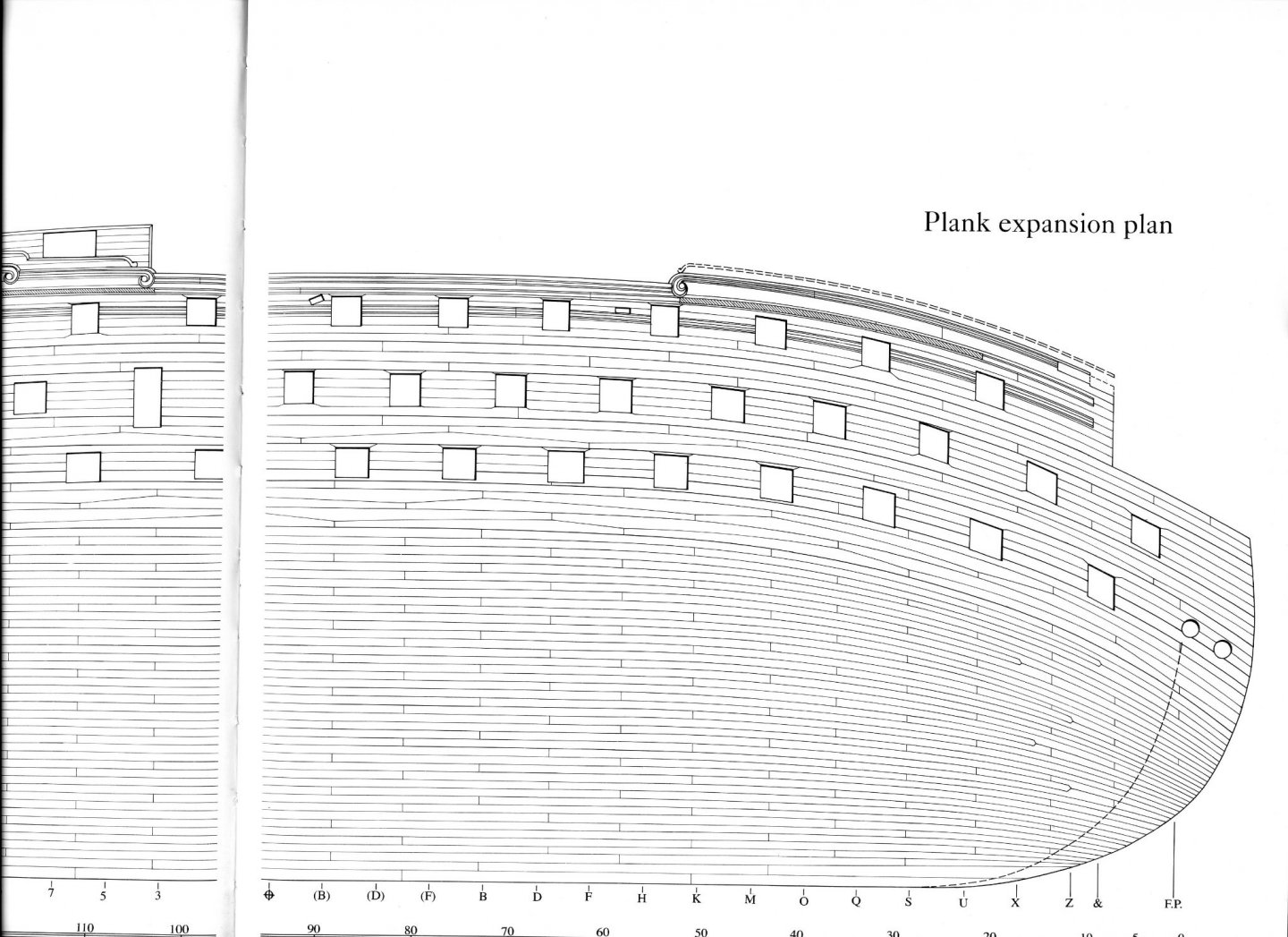
The Victory book by McGovan has a nice pic on the planking expansion.
-
Are there any decent clamps?
Dziadeczek replied to bigcreekdad's topic in Modeling tools and Workshop Equipment
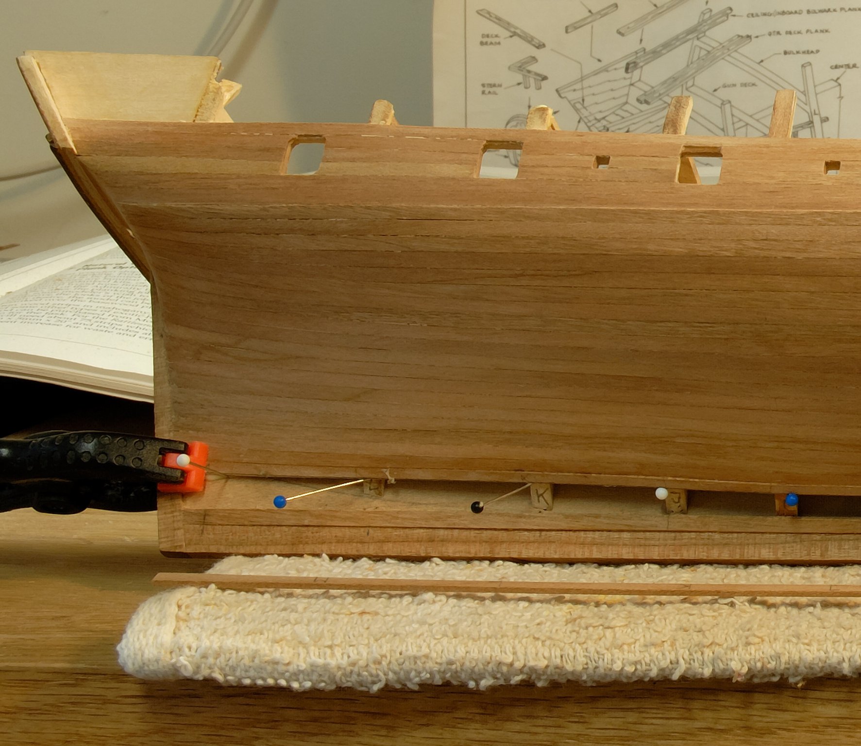
After all these years I found out, that if I properly spill and heat bend my planks off the model, I don't need any planking clamps afterwards. The planks should lay on the bulkheads almost perfectly, you only need to gently press them in place. For this I use ordinary sewing pins, sometimes those with colored heads. I gently tap them into a bulkhead with a small jewelry hammer, maybe two or three times - just enough to hold them in there, placing the tip of a pin directly under the edge of the plank, NOT THROUGH IT! That way, I don't end up with a hole in the plank, but rather a small hole In the bulkhead (which will be covered by planking anyway, so it won't be visible). This is my old model of the MS Rattlesnake, showing this process.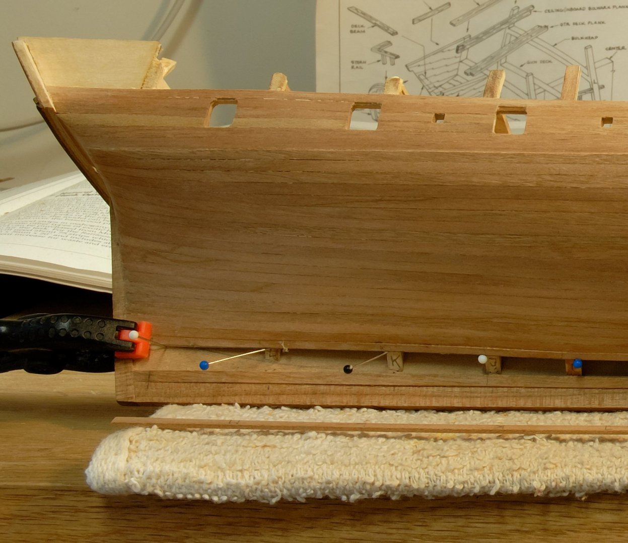
-
He is doing it correctly. La Créole 1827 by archjofo - Scale 1/48 - French corvette - Page 59 - - Build logs for subjects built 1801 - 1850 - Model Ship World™
-
Miniature Drill Bit Chuck for Dremel Tool?
Dziadeczek replied to turangi's topic in Modeling tools and Workshop Equipment
There is also the Pfingst rotary tool... -
Youtube photoetching tutorial
Dziadeczek replied to Nirvana's topic in Metal Work, Soldering and Metal Fittings
For more info on the topic, check out this link: Photo Etching - do it yourself - Metal Work, Soldering and Metal Fittings - Model Ship World™ I did not use the Micro Mark kit, since my pieces had to be way bigger - hence I had to build my own UV exposure lamp, get a bigger laminator and a bigger developing tank. I based the entire procedure on the very informative tutorial by Gene Berger (link included in the above mentioned thread), so I used different chemicals and exposure parameters than those proposed in the video. There are many ways to "skin the cat", one has to choose what is better for him and what is available in his area. This is definitely doable at home, but it is a learning curve - one has to determine all variables based on one's trials and errors. Do not expect to do it once and end up with gorgeous results! Patience!!! Have fun... -
Check out this link : Anyone using electric plank bender? - Modeling tools and Workshop Equipment - Model Ship World™
-
If it is Butapren (which I think it is), than its equivalent in the US is contact cement. Butapren also stinks fiercely, so I wouldn't use it for shipmodeling...
-
I have the same as you.
-
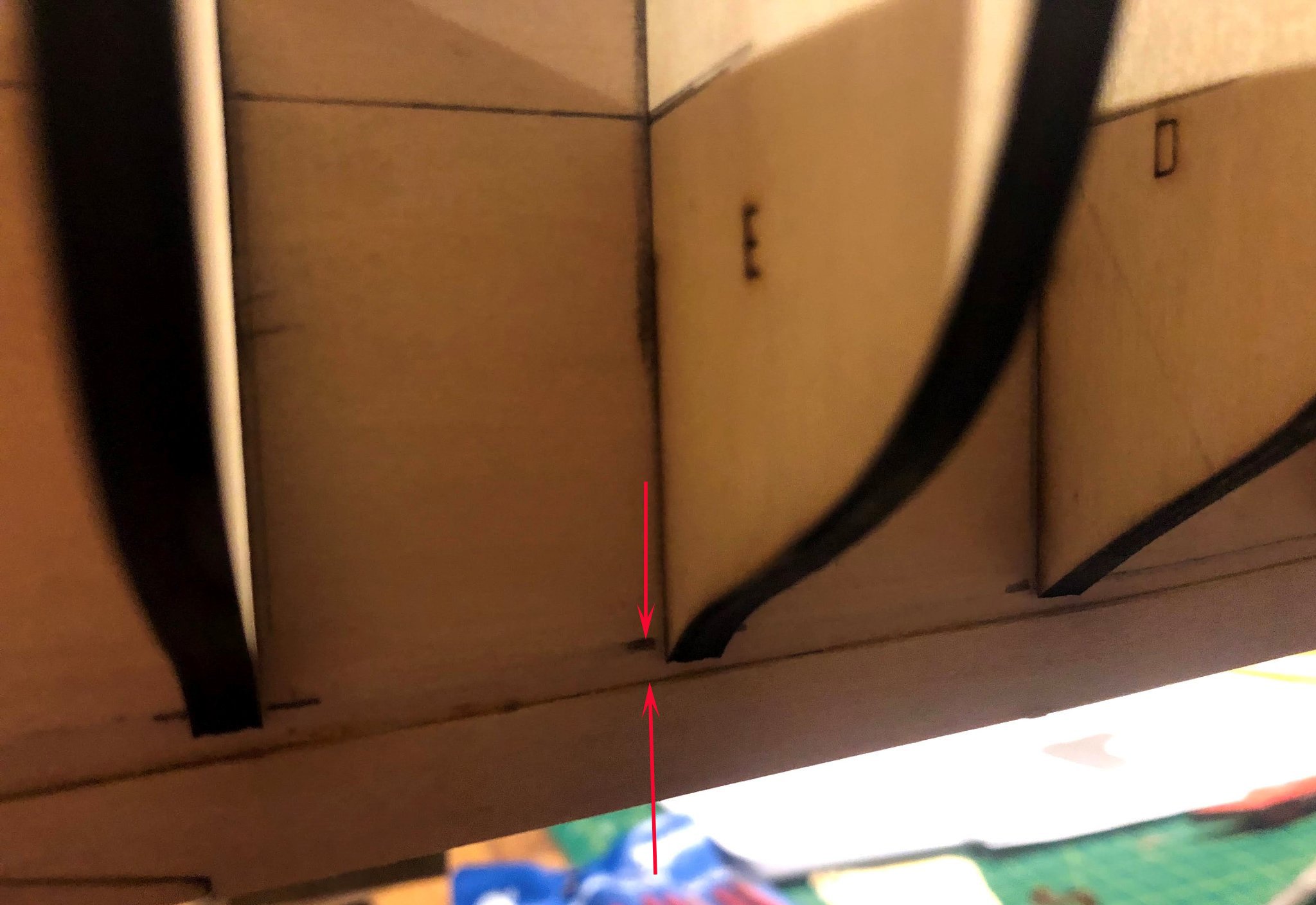
I would sand away the bottoms of these three bulkheads to the indicated by you, black line. Make sure though, that the distance between the arrows is the same as the thickness of your planks, so they fit snugly there, between the keel and the edges of all bulkheads.

-
When Divers Located The Ship That Survived Pearl Harbor, They Saw What Sank WWII’s Toughest Vessel (likeswifty.com)
-
Model Photography/Scheimpflug Principle
Dziadeczek replied to Charles Green's topic in Modeling tools and Workshop Equipment
Some time ago I took this pic of my (unfinished) model of the Rattlesnake, using focus stacking and Photoshop. It works.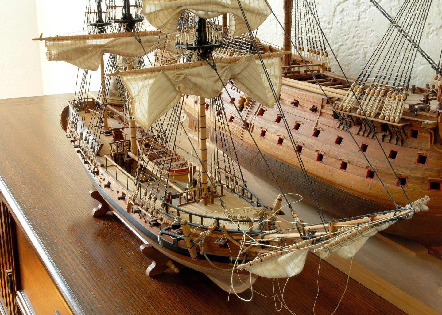
-
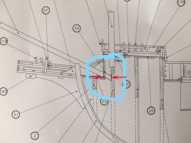
Just don't forget to lengthen the bowsprit with this extra dimension (see arrows).
-
Here is an email address I got earlier today from a friend in Canada for Wendy in Australia, (he uses her sewing skills for his models and swears by her). shipwheel@bigpond.com He also took the trouble to inform her that you would be inquiring about the sail set for your model. So, I think she will be expecting your email soon and you both can discuss the particulars. Regards, Thomas
-
In the good old days of the Seaway's Ships in Scale forum, there was a woman called Wendy from Australia, who used to take custom orders for making sails for models. I don't know her personally and never ordered anything from her, but supposedly her sails were excellent. If you are interested, I could get you in touch with someone who got her sails, and find out if she is still active. Thomas
-
Silver soldering
Dziadeczek replied to Dziadeczek's topic in Metal Work, Soldering and Metal Fittings
Thank you all for your input. After some thinking, I decided to go with a silver-enriched solder wire I obtained long time ago from Home Depot. I don't think it is called Stay Brite, but I forgot its exact name. I remember that it can be applied either with a soldering gun or with a torch and it is significantly stronger than regular 50-50 or 60-40 wire. I have a tiny soldering pen that gives me a lot more control than a mini torch, so I've been able to resolder those broken joints with this wire and give it a bit thicker joint (previously I was filing off extra thickness of solder to make it as thin as the brass rings. That turned out to be too thin and week). The joints will be covered with a rubbing pounch anyway, so they will be invisible. The solder joints don't get as black as the brass with Birchwood Casey, so I use just for these spots a different blackener - used for stained glass work, which seems to work there somewhat better. Thanks again Everybody!!! 🙂 -
Hi, I need help with the silver soldering of small brass parts. I am trying to make brass reinforcing rings for the masts of my 74 gun ship model. I prepared (cut) thin strips from a brass sheet and soon after I solder both ends together to close a ring, frequently they spontaneously break apart. I need a stronger medium. I tried to silver solder them, but every time I try to heat them, the flame from my torch immediately blows the tiny sliver of silver away from the place i put it, even before it gets melted. How do I keep it there?
-
Andrew Kudin is showing it here: https://modelshipworld.com/topic/20825-le-fleuron-1729-by-kudin-148-scale-kudin-andrey-youtube/page/5/?tab=comments#comment-753014 Except, his is making them from pear wood, as I understand.
-
I don't know, what the "general consensus" is on the treenail topic, so I will post my own opinion here. It all depends on the scale of your model - the smaller the model, the smaller and less visible the treenails should be. Perhaps no treenails at all, since they were practically invisible from ~15, 20 ft. on a full size ship. Calculate, what 15 feet would be in your scale and try to reproduce the same on your model. If your model is in the scale 1:64 and you want to show them, but at the same time you are concerned about overdoing it (don't want your model to look like it has measles), you can do it, using the same wood you used for planking (boxwood). End on, it will be a bit darker than your planks, especially after you oil it. You can entertain the idea of cutting your treenails with a special treenail cutter from Vanda Lay Ind. here: https://www.vanda-layindustries.com/html/treenail_maker.html I have this gadget for many years - it works well with many species of hardwood, will work with boxwood as well, but not so well with bamboo (too fibrotic for this cutter). If you want to use bamboo skewers, go with Jim Byrnes draw plate (he is a member here). The process of drawing treenails from bamboo through his plate is a bit tedious and bamboo tends to break while you push it through, so go easy - after a few trials you'll figure out the mechanics, pulling steady, no yanking, just steady pull, gently grasping the skewer with tongs or pliers. Andrew Kudin is showing it here: https://modelshipworld.com/topic/20825-le-fleuron-1729-by-kudin-148-scale-kudin-andrey-youtube/page/5/?tab=comments#comment-753014 If that scares you too much, I would recommend just marking your treenails with a cut off sharp end of your medical needle. with a gentle circular motion. Just enough to make a mark of a tiny circle - after you oil the hull, those circles will be a bit more accentuated, just enough to show them. You don't want to show them too much, or make them too large, so figure out before how big they shoul be in your scale. If you are the beginner, I would in fact recommend you to do just this. Less work, less chances to mess it up, and the end result may be the best. Happy modeling! Thomas
-
Edge Gluing Planking
Dziadeczek replied to Neil10's topic in Building, Framing, Planking and plating a ships hull and deck
As far as I understand, some kits are designed for double planking, especially intended for beginners, with the idea to learn how to plank on the first layer and do the second layer properly. But, if you do the first layer properly (observing spiling and shaping of your planks) it will look beautifully, so there will be no purpose for the second layer to cover up mistakes. If however, you don't properly spill and shape the first layer, you won't learn the process and repeat it with the second layer also. What's the point? If you read and understand the process, you should be able to do it properly. Don't get too intimidated, the explaining it in words is harder than actually doing it. I too was anxious before my first attempt on planking, but plunged in it, and it turned out OK. Use a good pair of proportional dividers, or paper strip technique, be precise in measurements, check everything twice before cutting and glueing and you should be fine! I too recommend reading those tutorials here, but perhaps also a brochure "Planking the build up ship models" by the late Jim Roberts. In fact, I learnt the process based on this brochure, before the time the above mentioned tutorials first appeared on the MSW website. -
You might obtain ebony in exotic hardwoods outlets, if you are lucky. It is harder and harder to locate it though. Also, it is stinky expensive! I once managed to find it in my local exotic hardware lumber yard (this place doesn't exist anymore), but luckily I then snatched two quite large boards of it. I still have most of it and use it very carefully and sparingly. It is a very dense and heavy wood. Ebony also is difficult to work with, it is very stiff, springly and hard to bend. Some people are allergic to its dust, so wear a face mask while cutting it and sanding it. Other than that, it is quite similar to boxwood as far as its texture. It cuts, carves and turns nicely, leaves a sharp edge and glues well. I once used it for some railings and decorative ornate elements on my French 74 guns. I also turned some deadeyes from it. But for triple wales on my Frenchie I used cherry instead. Cherry heat bends much better than ebony. After preshaping the wales and glueing them onto the frames, I stained them with ebony stain by Varathane. When looking at them and comparing with genuine ebony railings and other details, the wales are virtually indistinguishable as far as color and texture. I am not sure about other ebony stains from different manufacturers, like Minwax and such... It is therefore always a good idea to first test them on a piece of scrap hardwood and see if it meets your expectations. So, as far as making some details from ebony, that don't have to be bent too much, it is a nice wood to work with, but if you have to significantly bend ebony strips, use other hardwoods instead and stain them, rather than struggling with ebony, provided that you can first locate it locally in your area. Regards, Thomas
-
Edge Gluing Planking
Dziadeczek replied to Neil10's topic in Building, Framing, Planking and plating a ships hull and deck
I place a drop of PVA white glue, or Titebond glue on top of my index finger and run the edge of a plank along it, making sure it gets just barely enough glue on its entire length. Any excess can be wiped off, if necessary, by repeating the above. If some small amount of glue still oozes out from the joint, I wipe it off with a wet rug. Generally it is enough to be able later on to apply a layer of oil or stain. If however there are some small spots where oil/stain did not penetrate, I take an edge of a small chisel or a one sided (industrial) razor blade and carefully scrape off this area to the bare wood. -
Splendid! Why not glueing them to the shrouds with, say, a drop of white glue to keep them there, and then wrapping them around the shrouds with a thread?