


Glenn-UK
-
Posts
2,732 -
Joined
-
Last visited
Content Type
Profiles
Forums
Gallery
Events
Posts posted by Glenn-UK
-
-
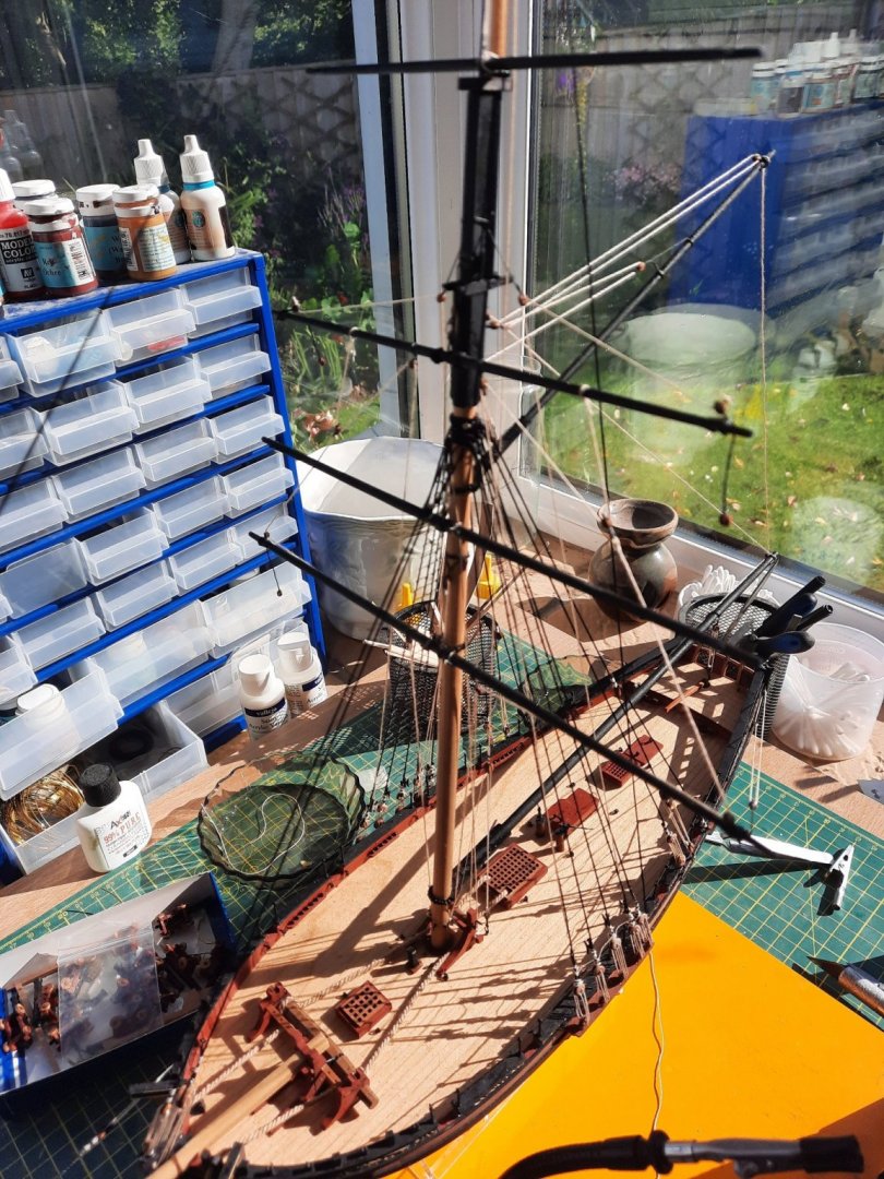
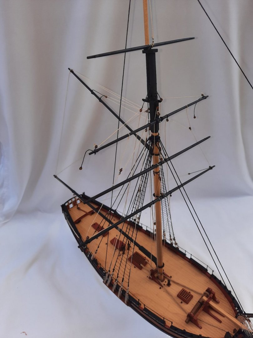
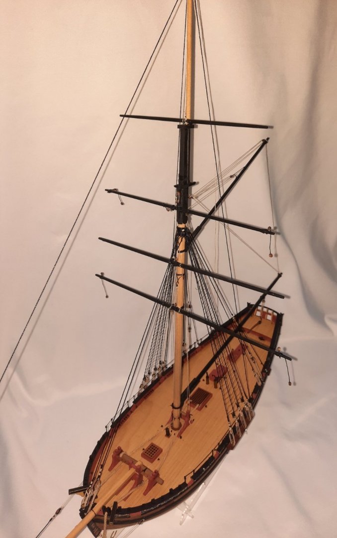
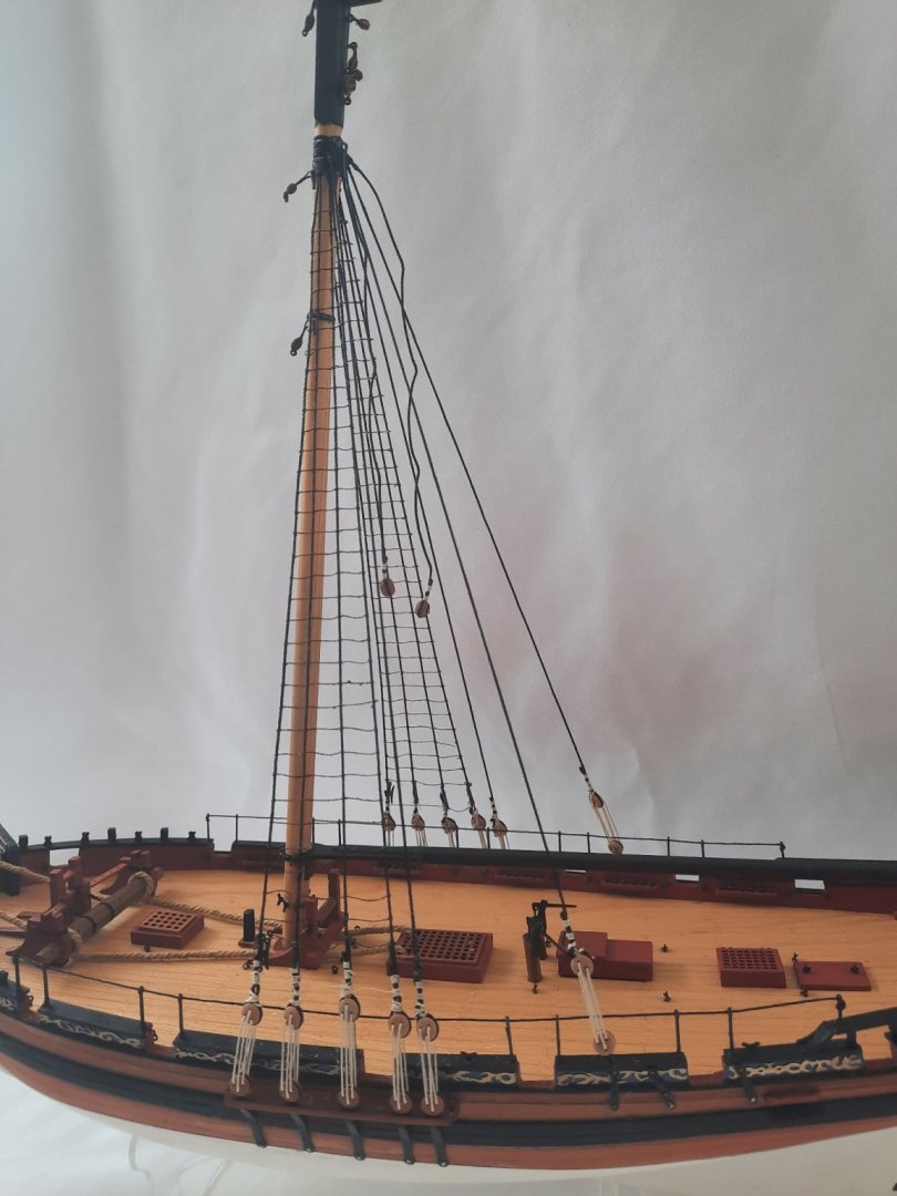
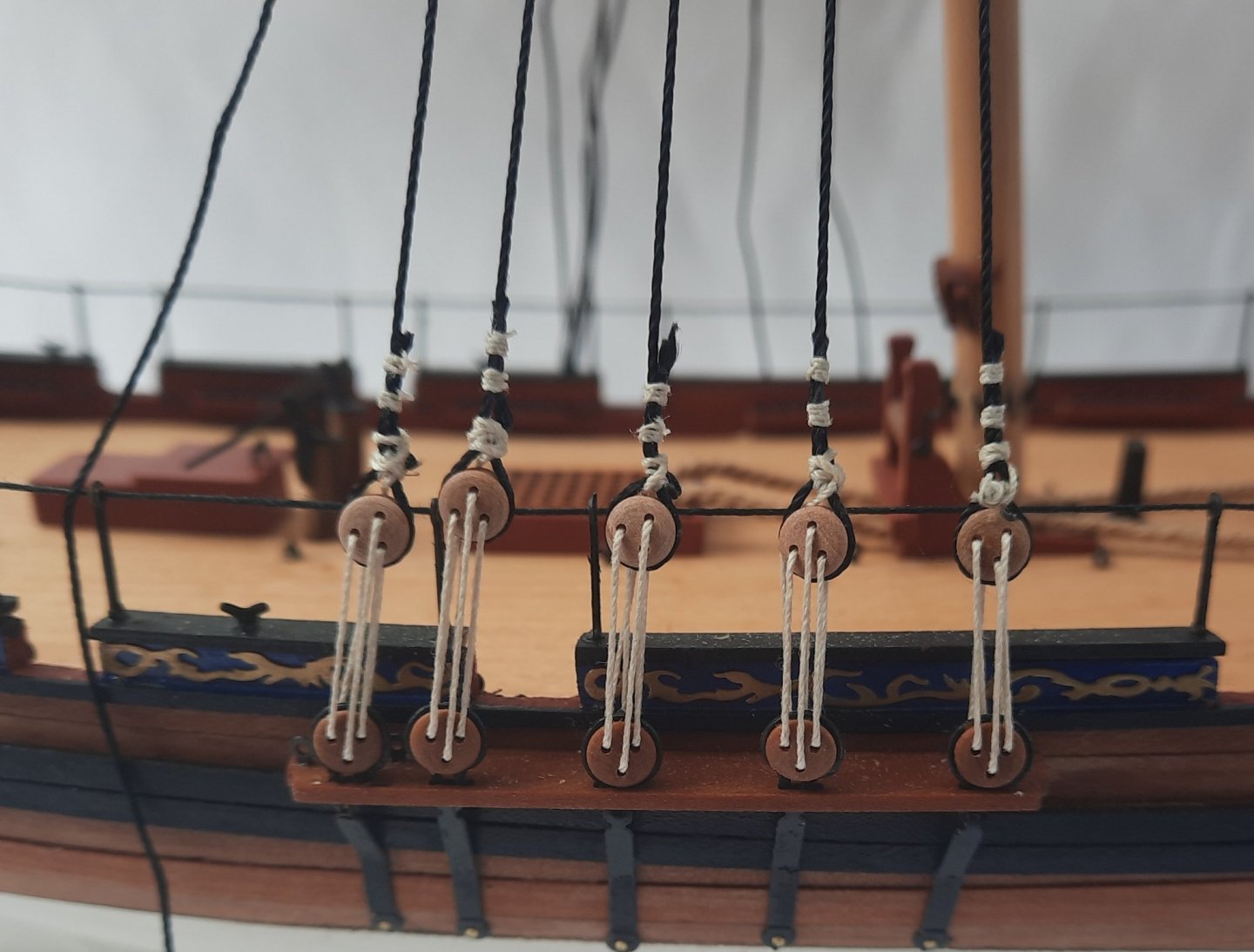
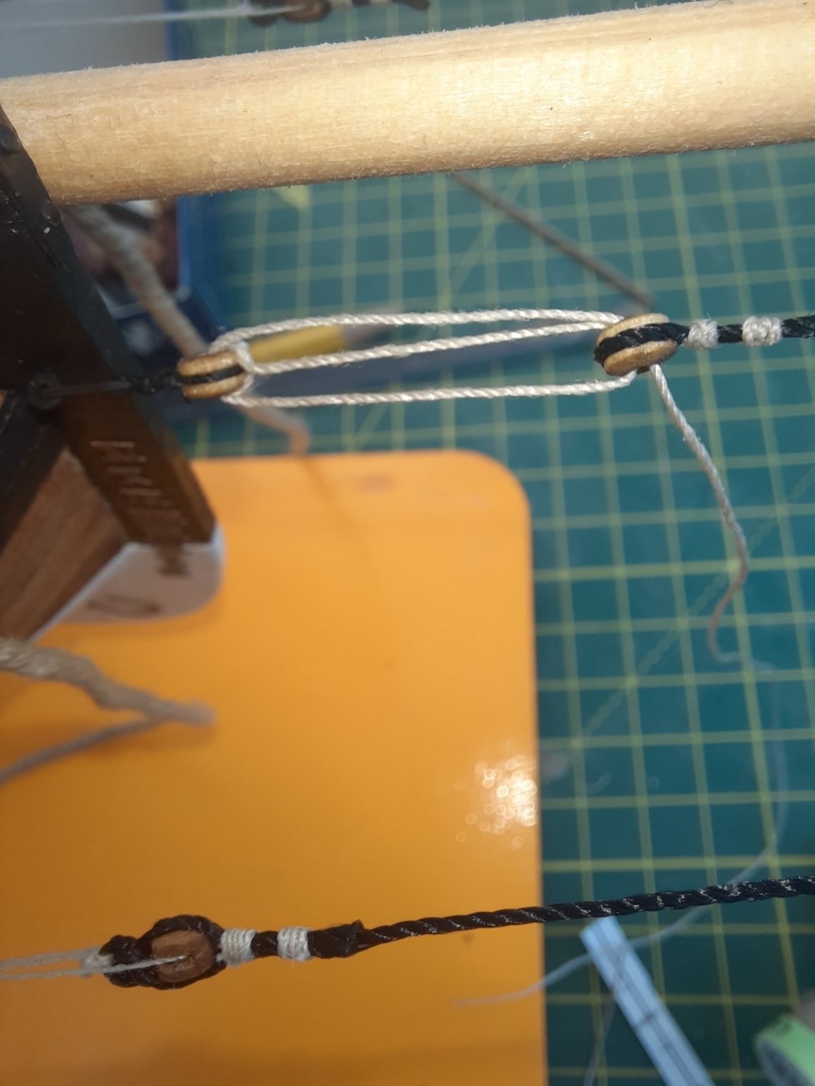
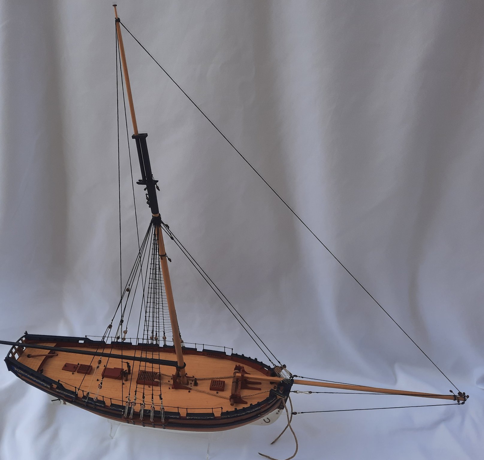
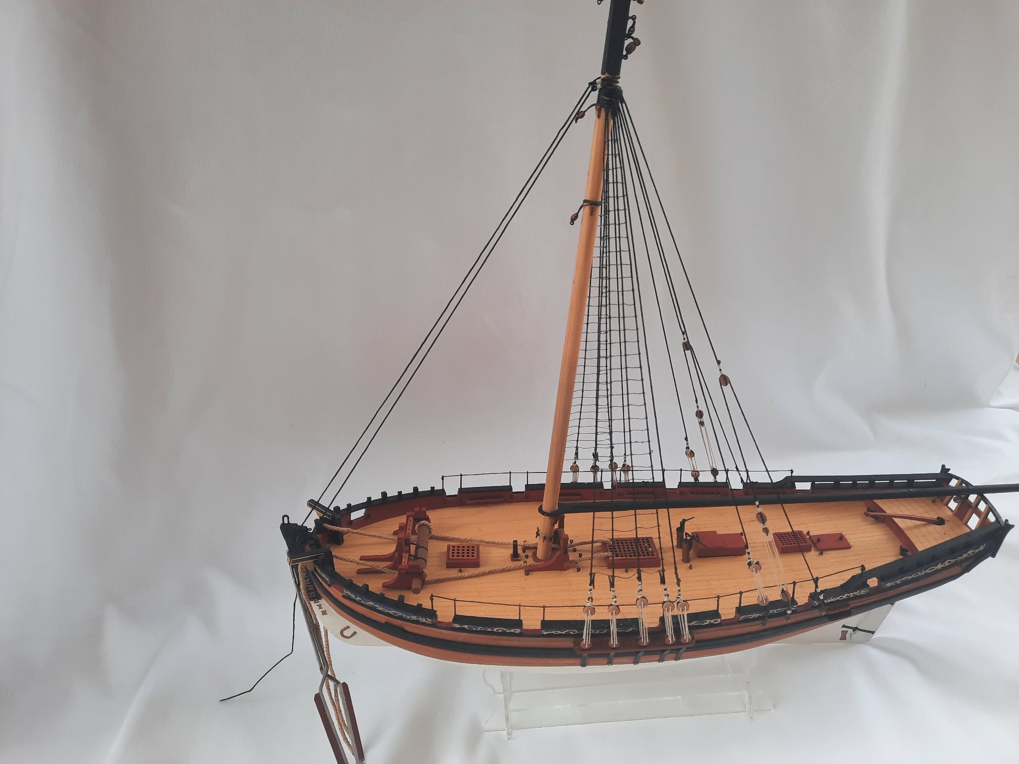
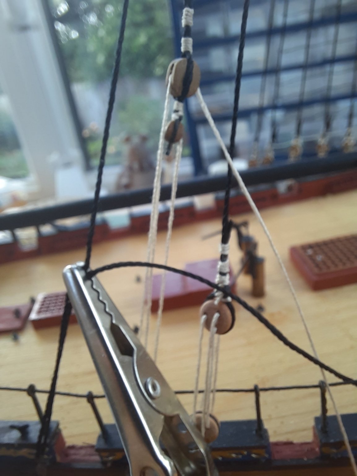
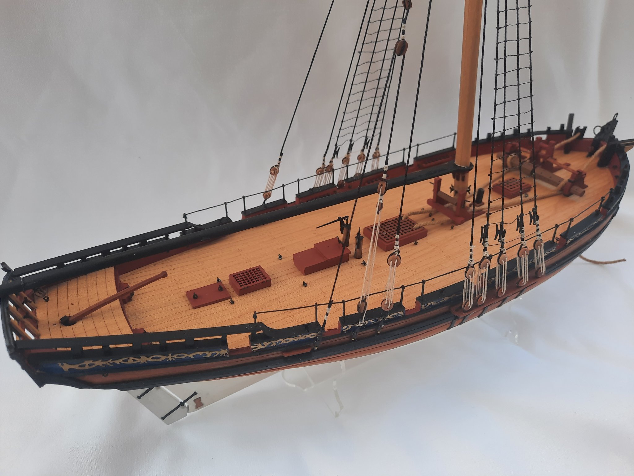
Here are some more pictures of the Cutter Alert. I have moved on to fitting the yard braces. This is not too difficult, it is simply a matter of reeving the thread through the blocks from point to point, ensuring the lines are not tangled with existing lines as they are taken to the different belaying points.
I think there is about 2 or 3 days of work left to complete the build, but as my time is limited at the moment I think will probably be completed sometime next week.
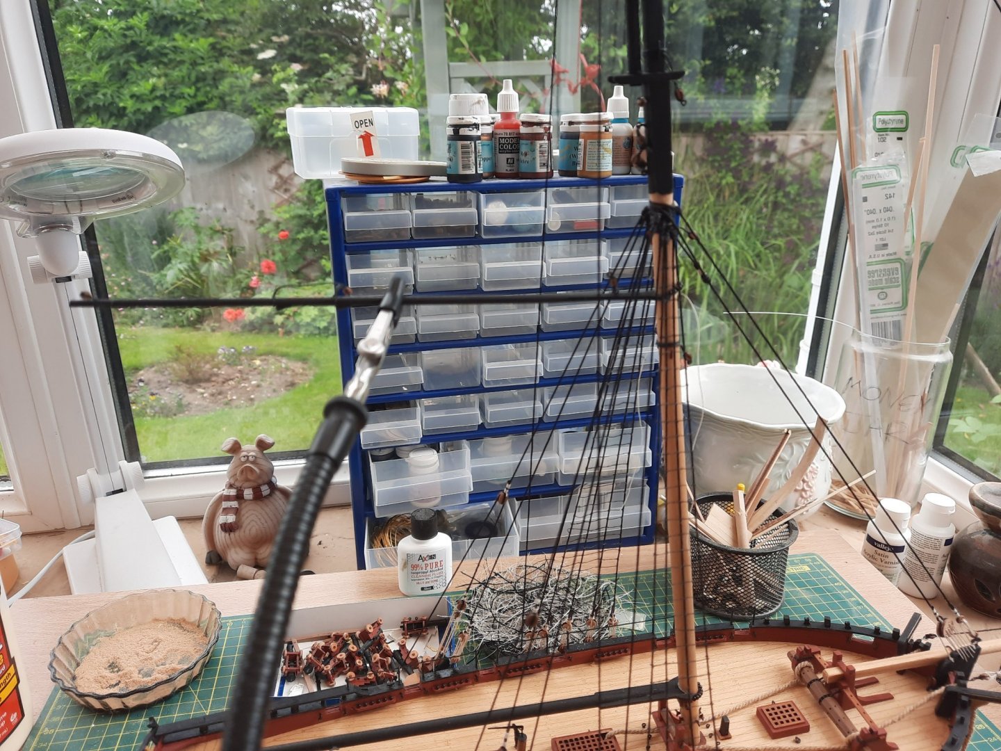
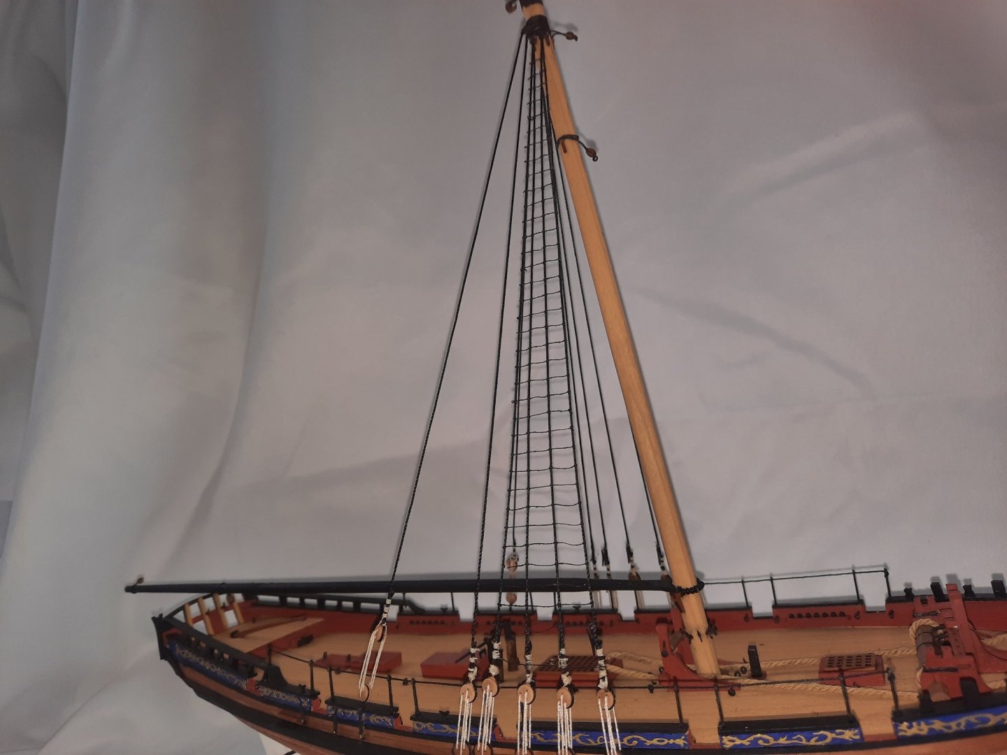
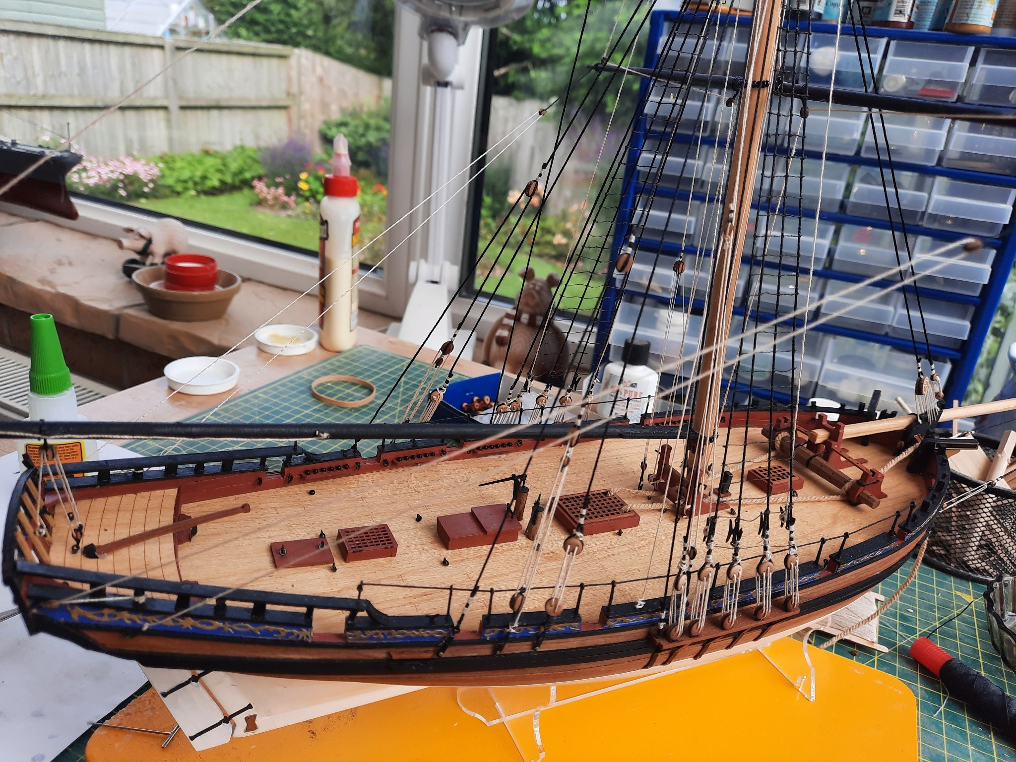
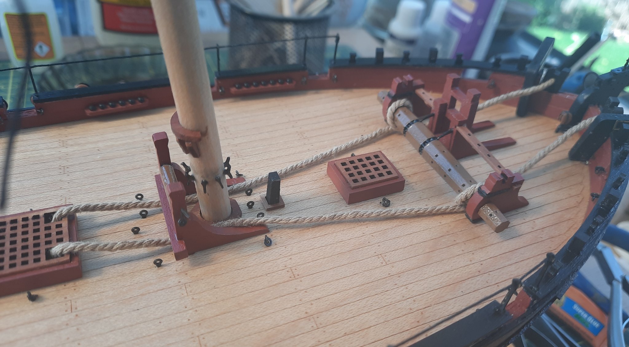
Work in progress on my untidy workbench. The vista is very nice.
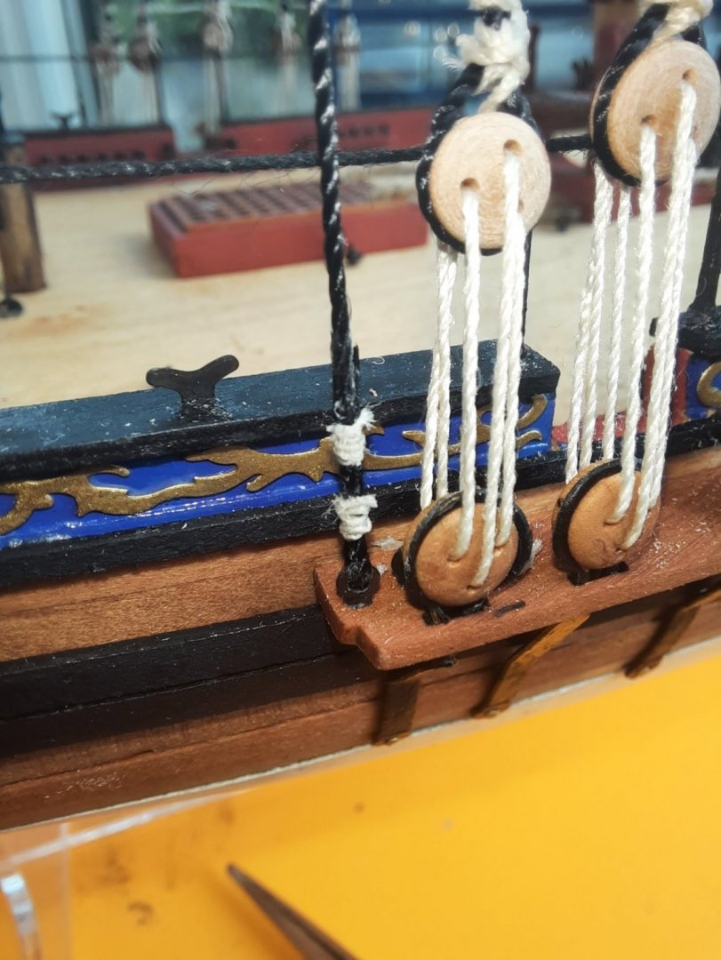
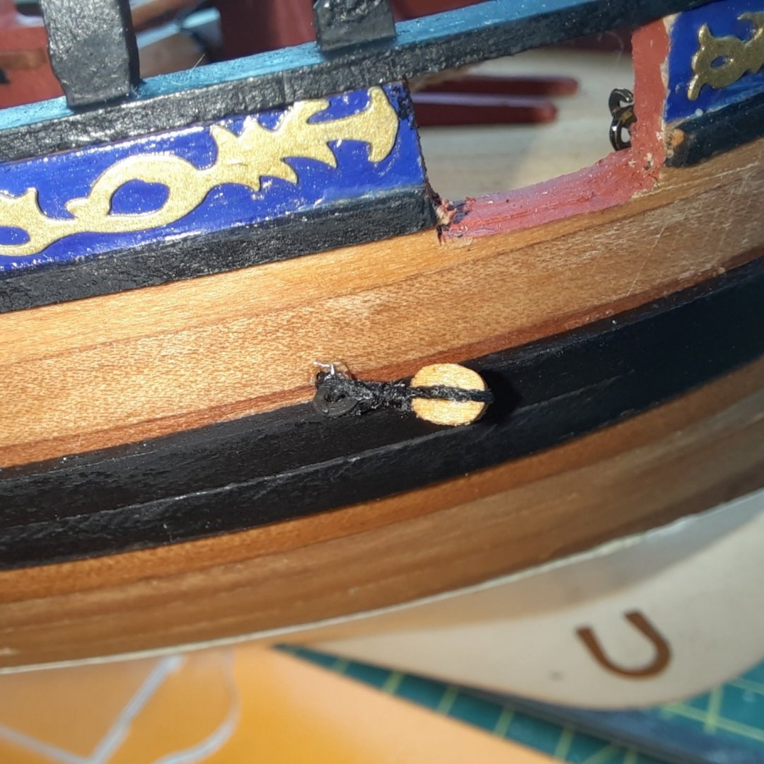
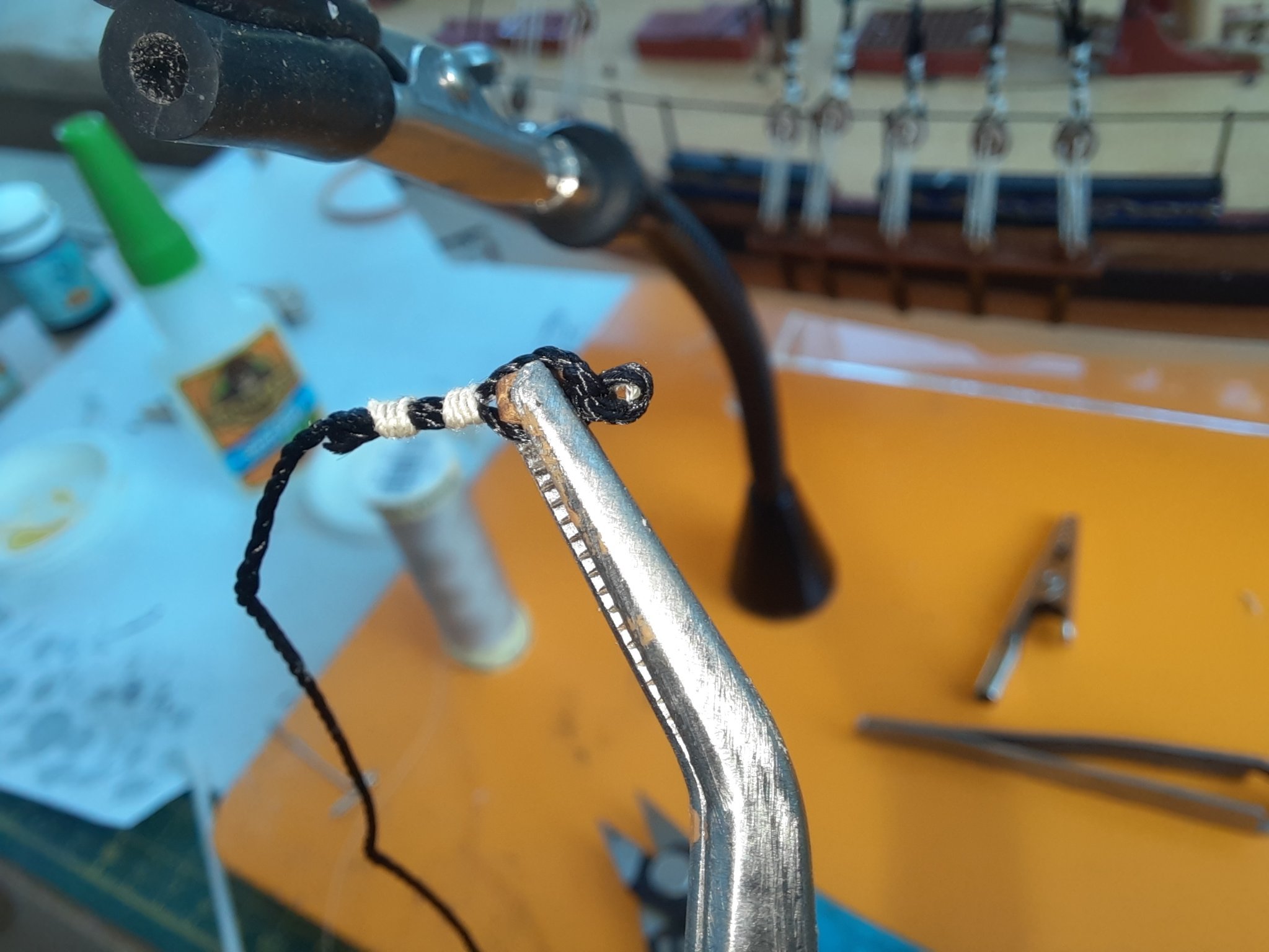
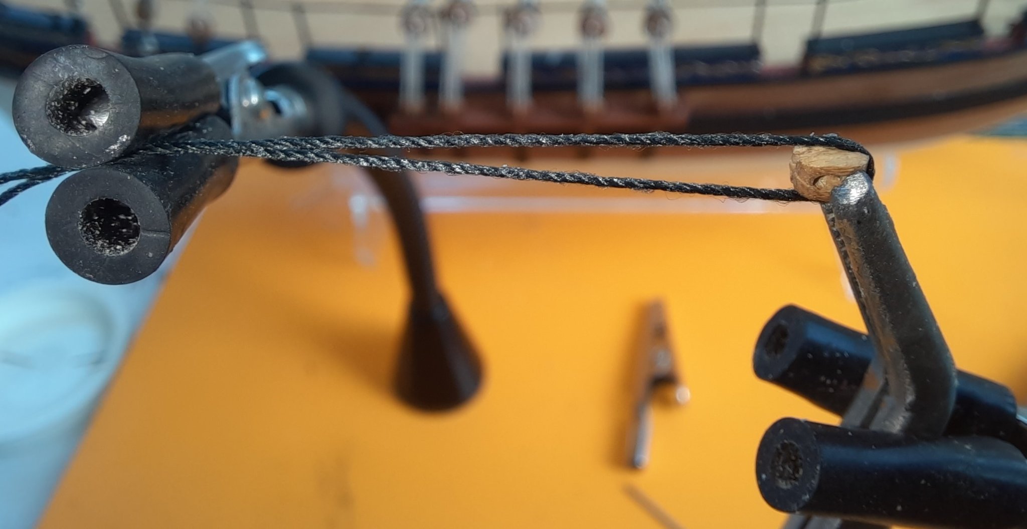
Spreadsail yard brace rigged but not belayed
Spreadsail yard brace rigged and belayed
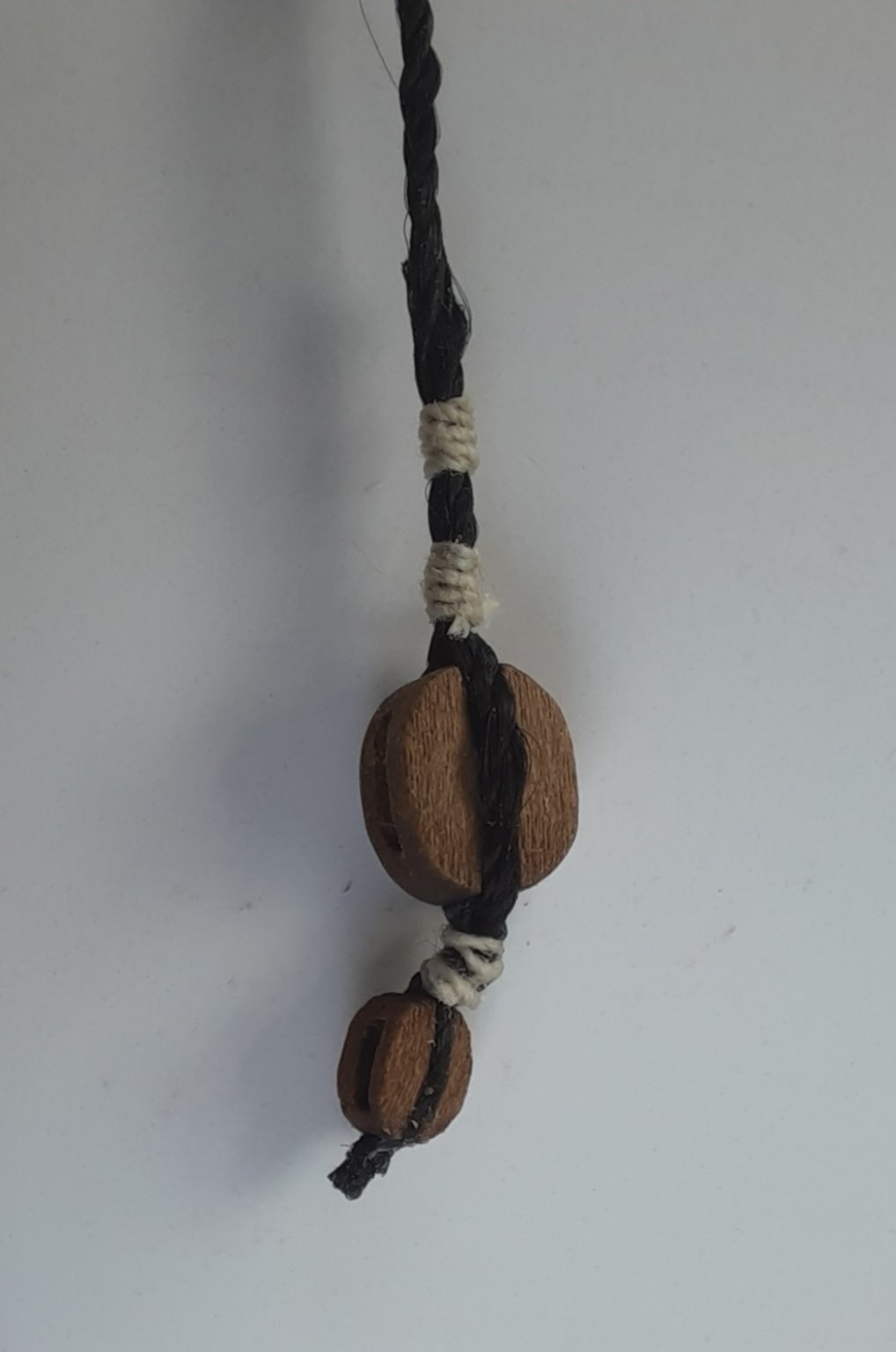
Spreadsail yard brace block

Completed spreadsail yard brace

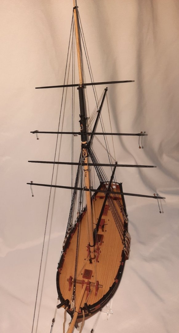
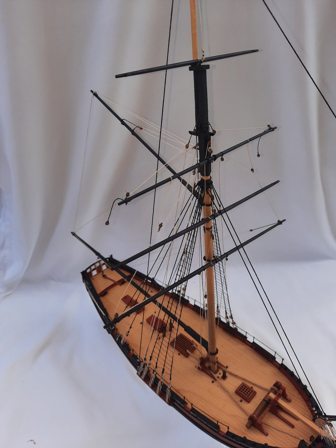
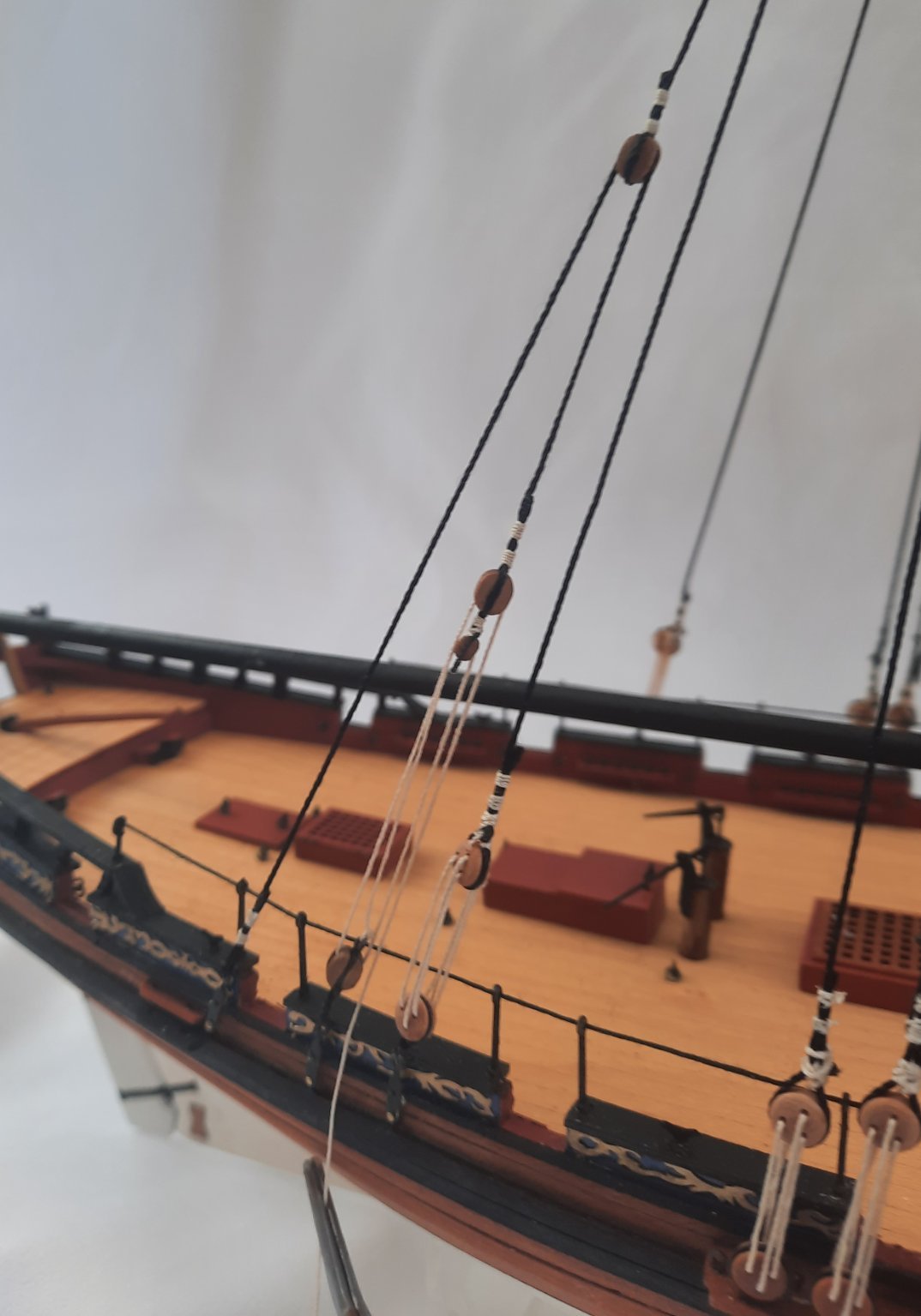
Current state of rigging
- Ryland Craze, CiscoH, drjeckl and 6 others
-
 9
9
-
Great news, on both fronts. Bismark is a build I will look at after the Sphinx, unless Chris has a new kit available!
- FrankWouts and JeffT
-
2
-
I am now on the home straight with the rigging and there is only a few more days left. That said my time in the shipyard will be a bit limited for the next few days. I am eagerly waiting for the release of The Sphinx and fingers crossed that @James H is making good progress with the masts and yards and that @chris watton is making good progress to allow for the pre ordering of the kit in the very near future.
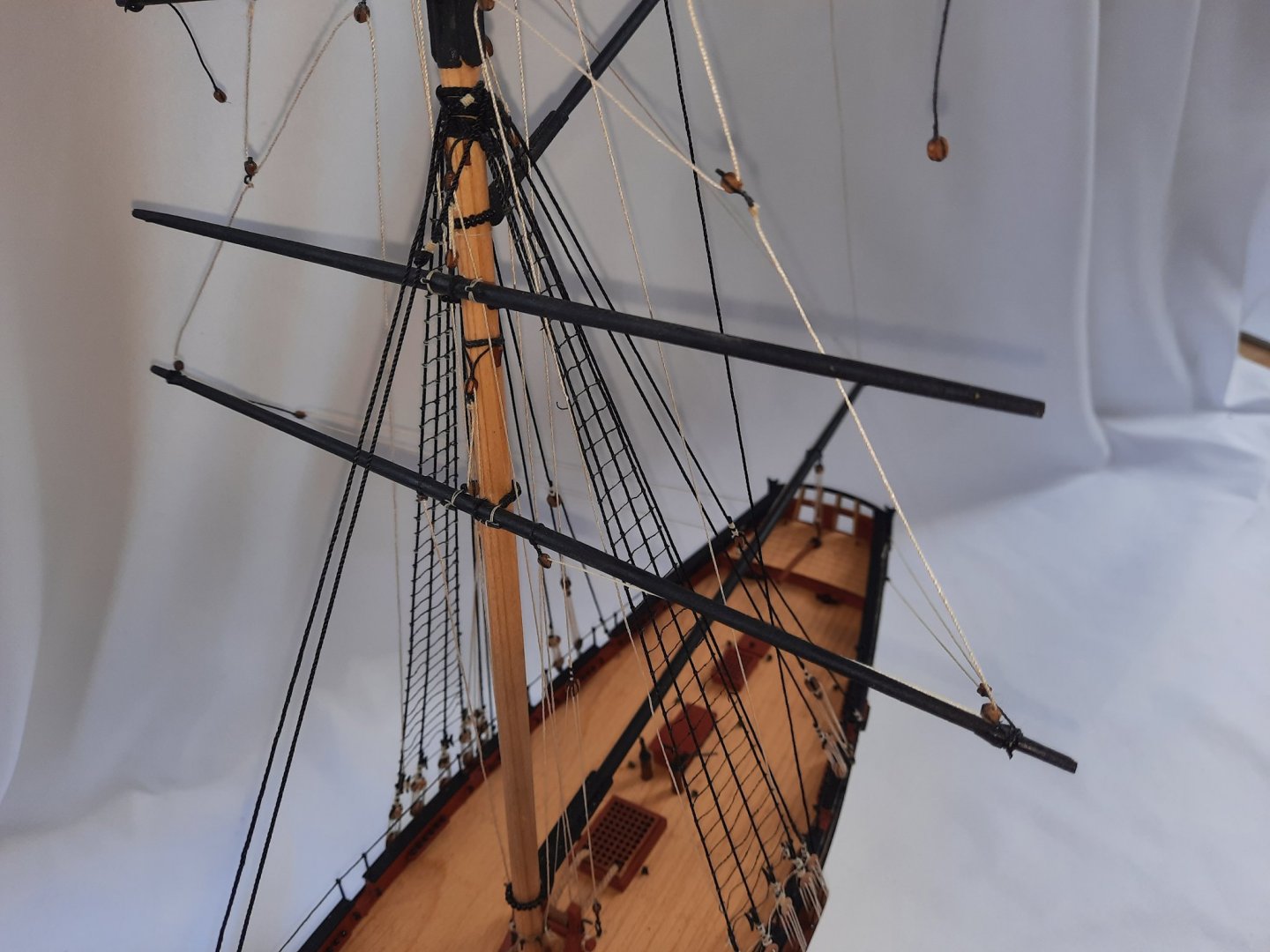
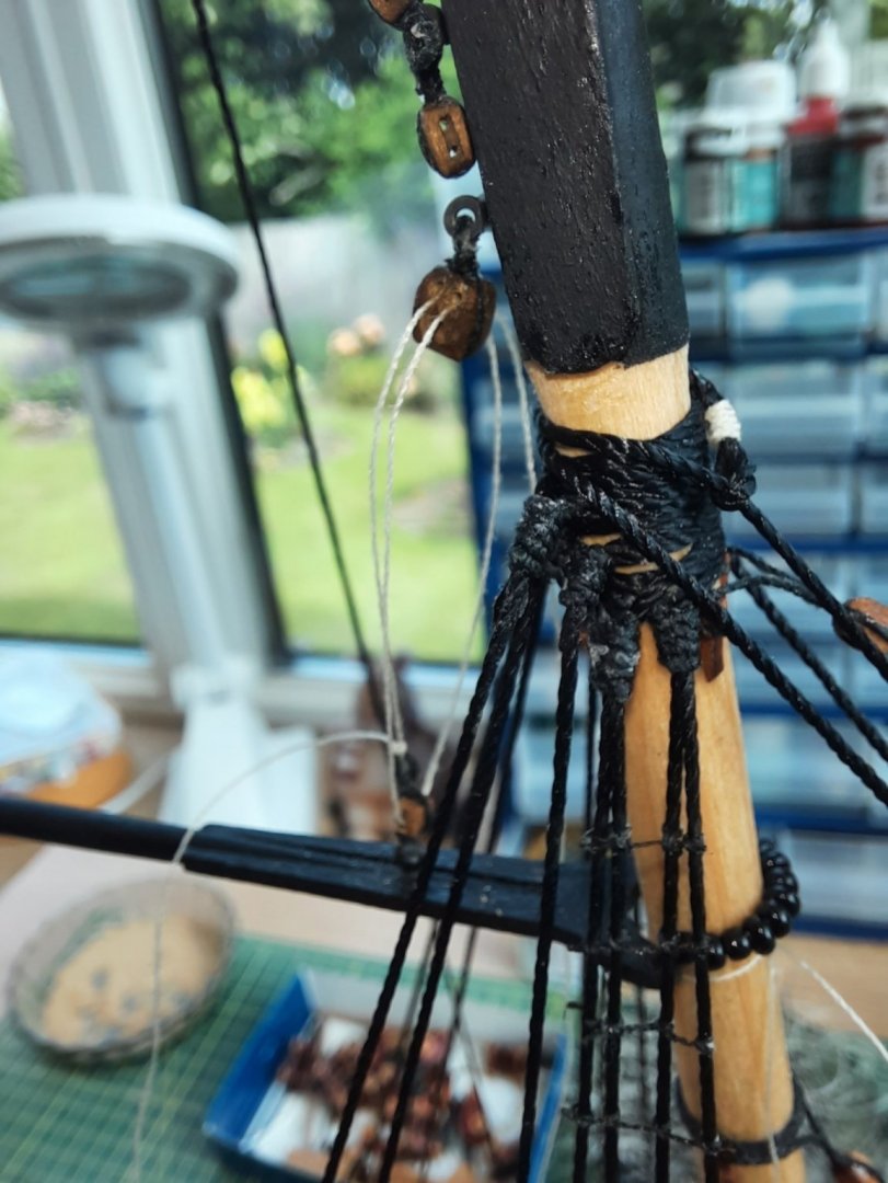
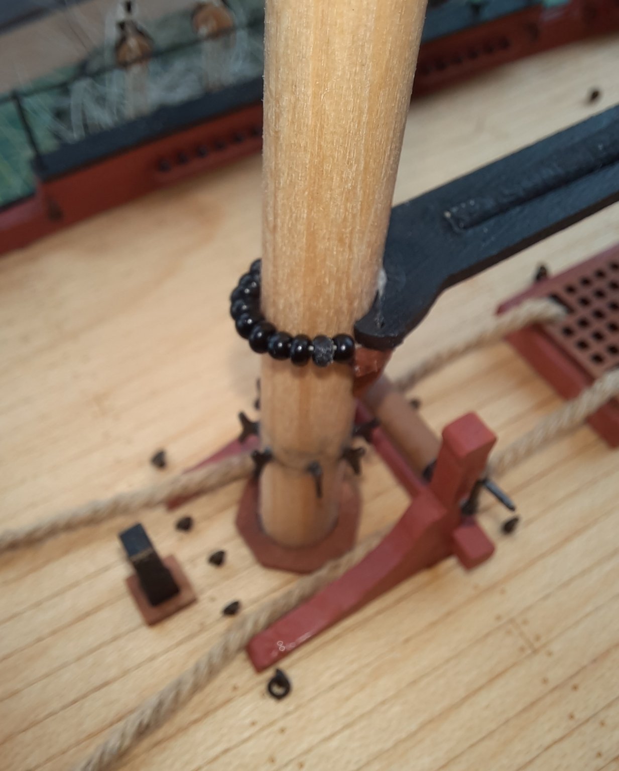
Today I added the 4 x yards and their lifts to the main and top mast.
Before the yards were fitted I ensured the various threads could be reeved through the various yard and mast blocks, and where necessary I ran a micro drill bit to enlarge the block holes. Once I was happy with how the threads could be reeved I applied some ca gel to the pins on the yards and secured them to the main and top mast using parrel beads for three of the yards. I then added the yard lift rigging. I have included a selection of photos showing different aspects of the yard lift rigging.
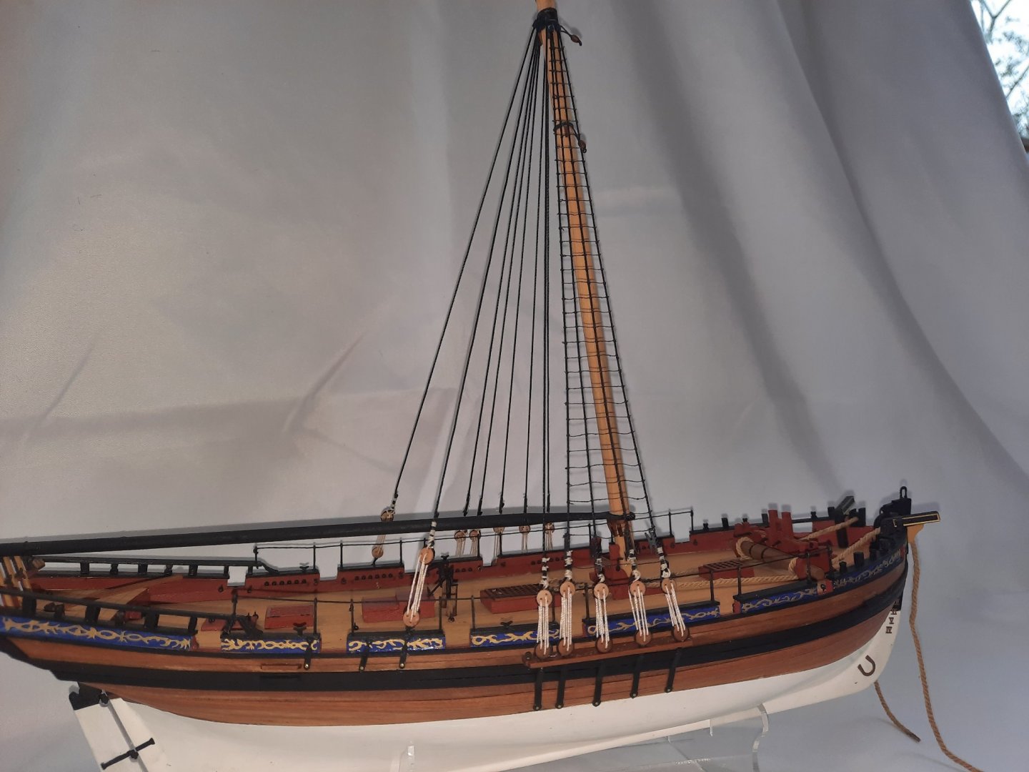
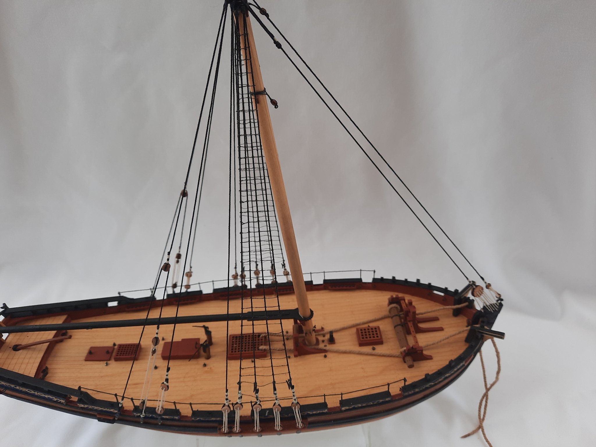
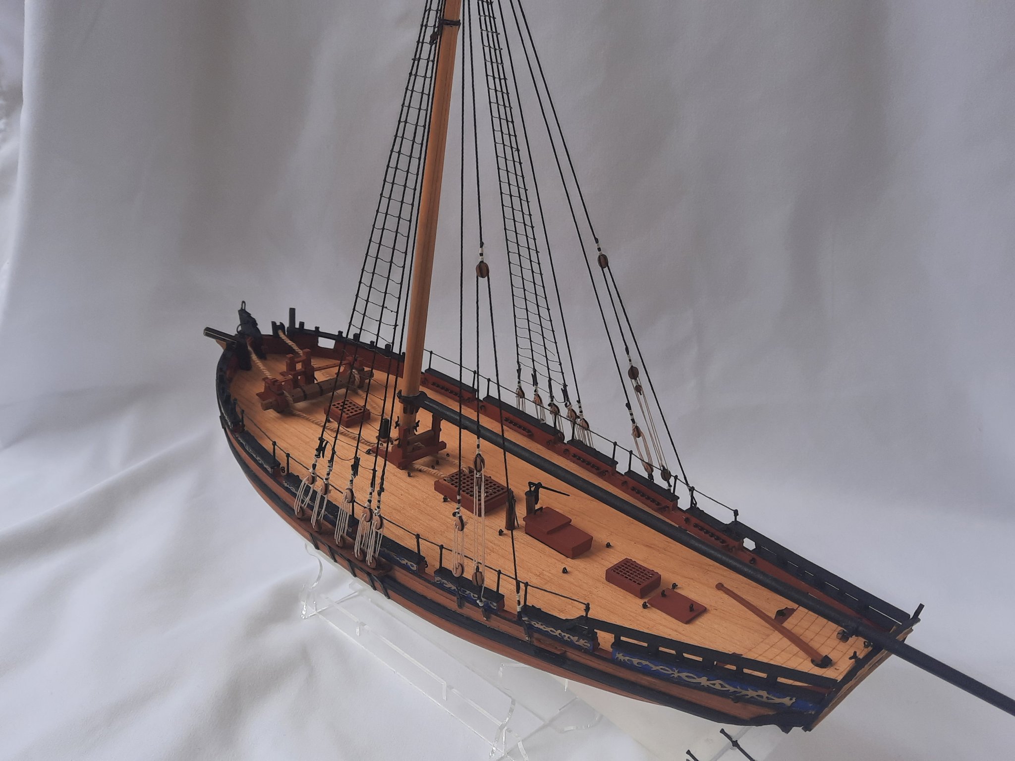
The current build status
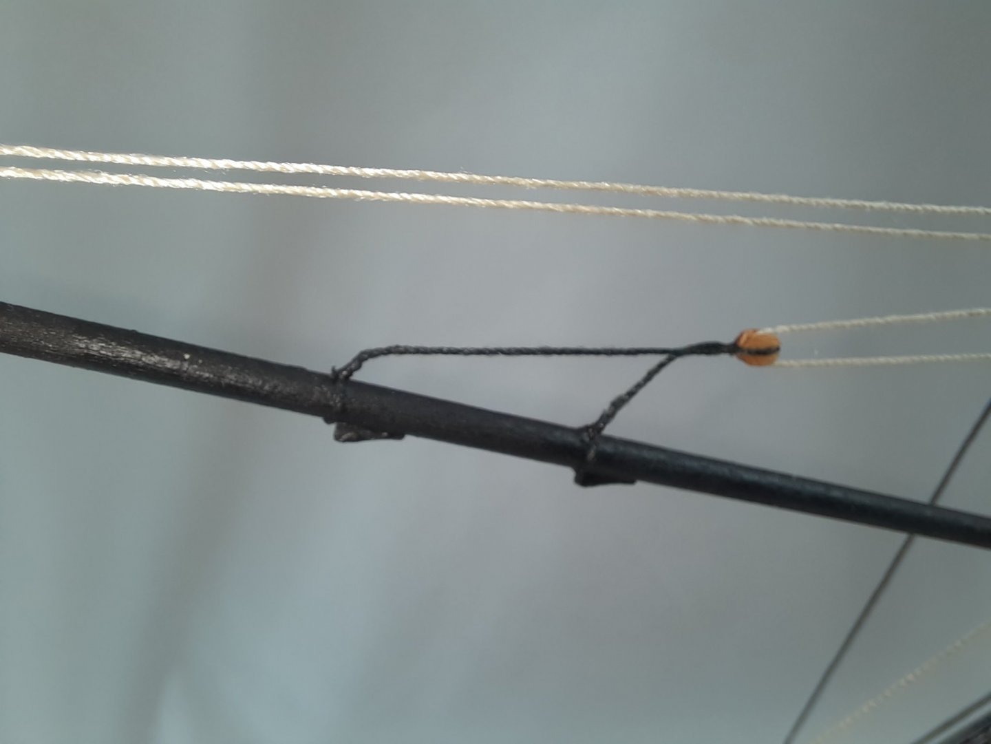
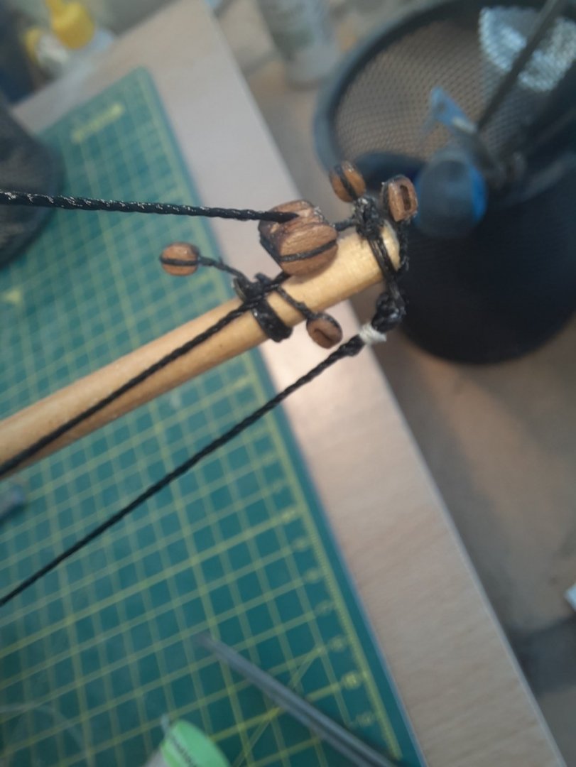
Spreadsail Yard Lift

Squaresail Yard Lift
Squaresail Yard Lift Belaying

Spreadsail Yard Lift and Topsail Yard Lift Belaying
Yards
- bruce d, DelF, chris watton and 3 others
-
6
-
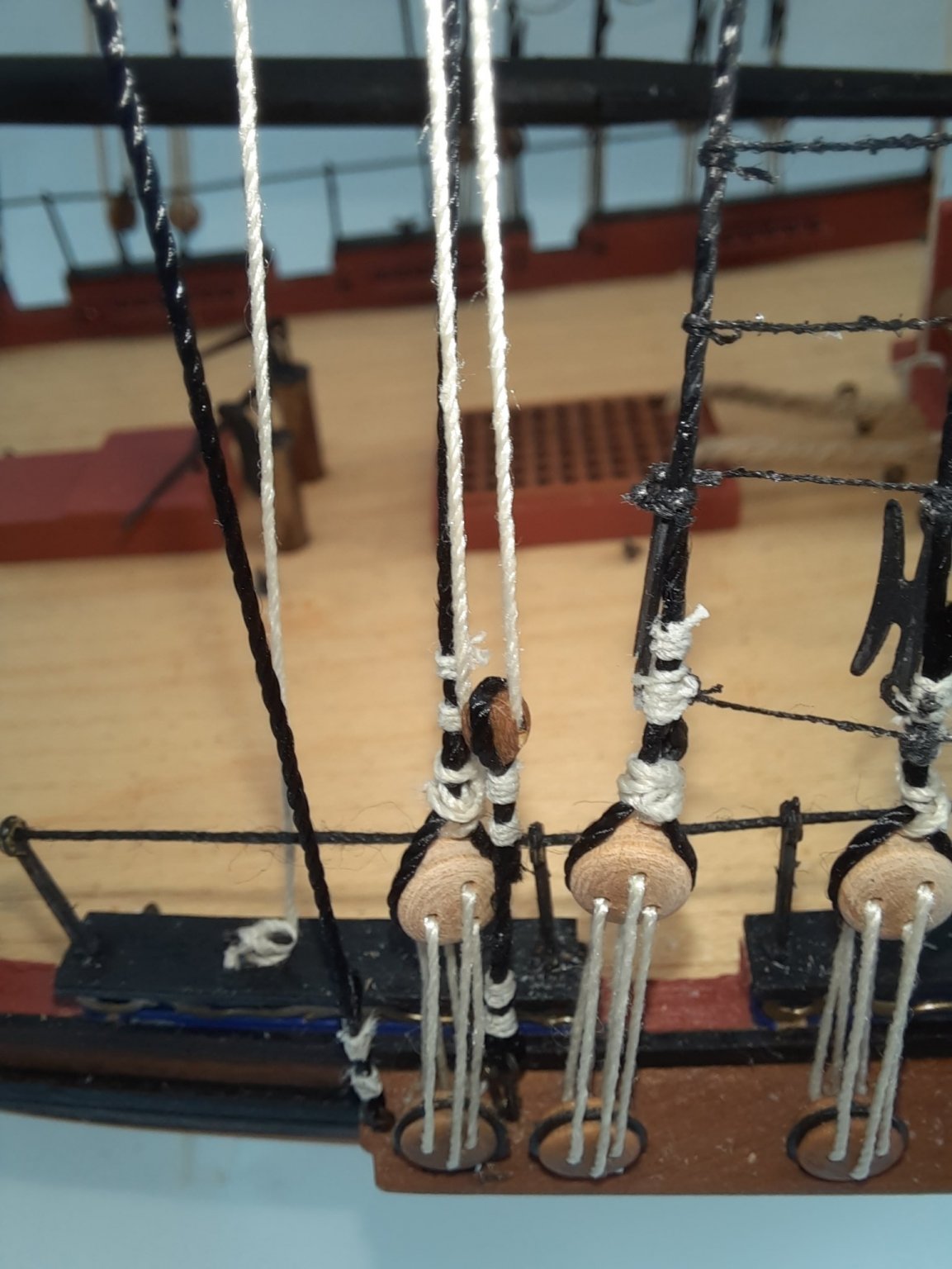
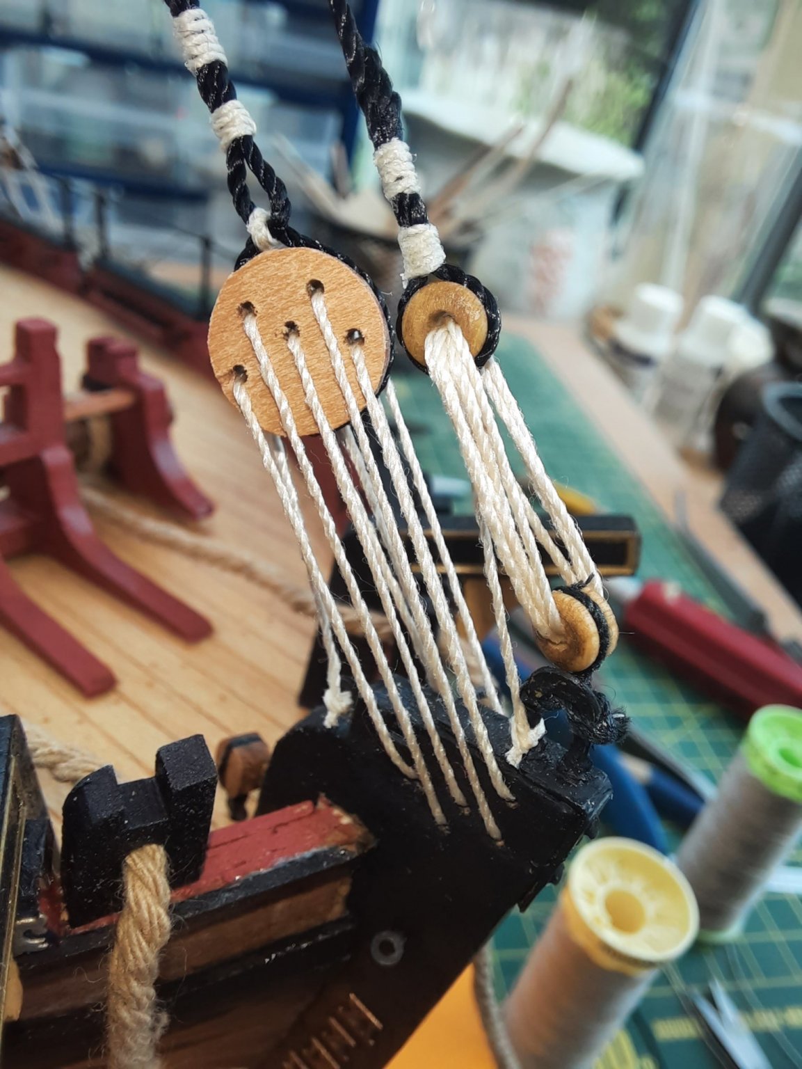
The driver and main booms have now been rigged. When completing this task I made a note for any future builds to check and enlarge as necessary the holes in the various blocks before they are fitted to masts and yards so that the threads can pass through them. Initially I had great difficultly trying to get the stiffened ends of the 0.5mm and 0.25mm natural thread to feed through the 3mm single and 4mm double blocks. It was not an easy task to enlarge the various block hole in situ, but thankfully I was able to do so without damaging anything.
DRIVER BOOM
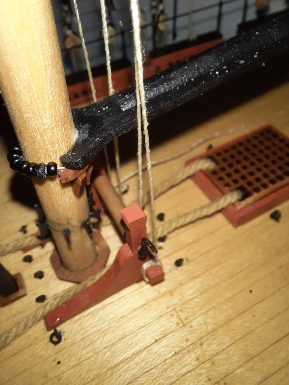
The driver boom was held in position using the quad hands so the parrel beads could be added to secure this boom to the main mast.
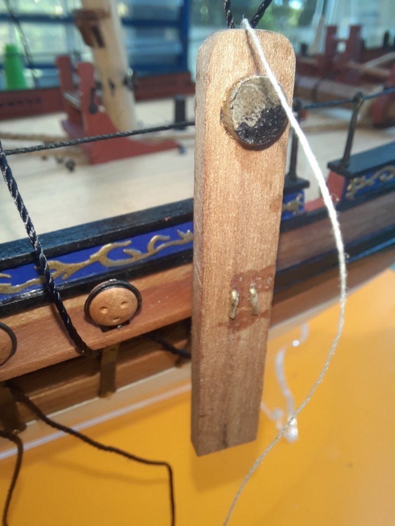
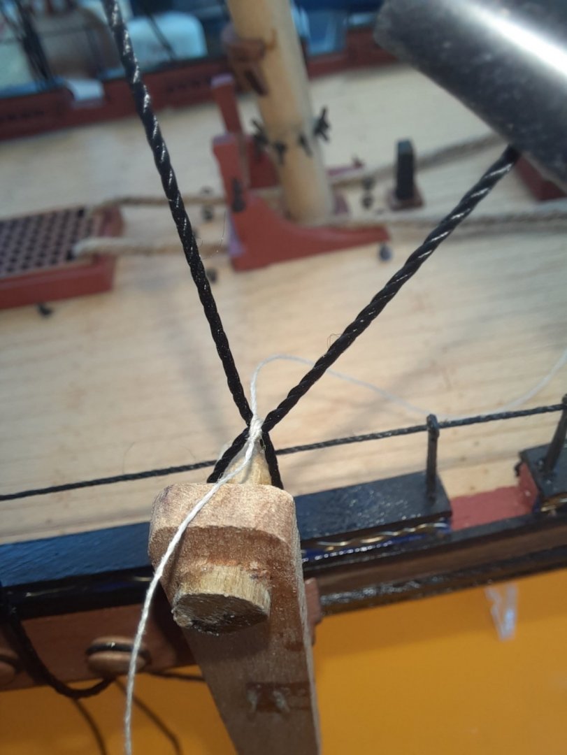
I then moved on to adding the driver boom lift. I cut a length of 0.25mm natural thread and once I had enlarge the block holes it was a simple task to rig. The end was taken down to the belay point on the main mast bitt
The final rigging of the driver boom was a bit more complex, but in reality it was simply a case of running the thread from point to point.
From its starting point from a loop on a block on the main mast it is fed through the end block and then returns and is fed through the mast block.

The thread then goes back and is fed through the mid point block on the driver boom and then returns back to another block on the main mast where the thread is taken to the belaying point.
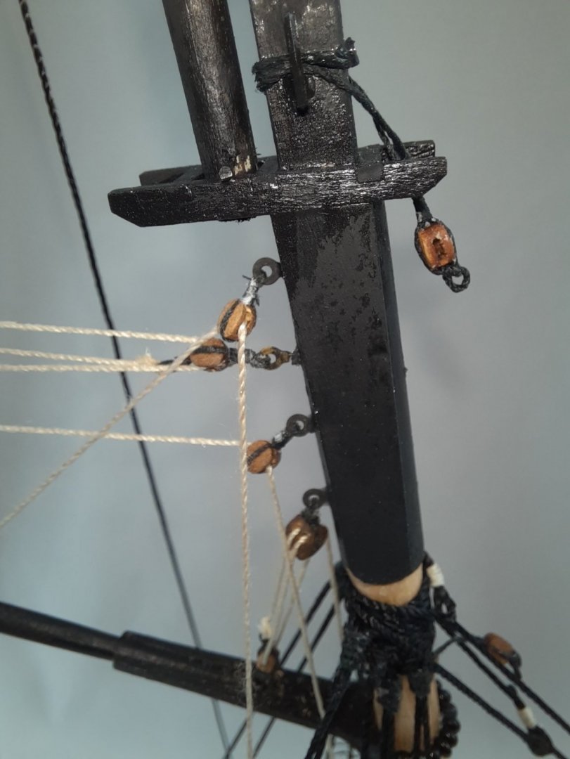
This photo shows the mast blocks
This photo shows the driver boom before the final belaying to the main mast bitt.
MAIN BOOM
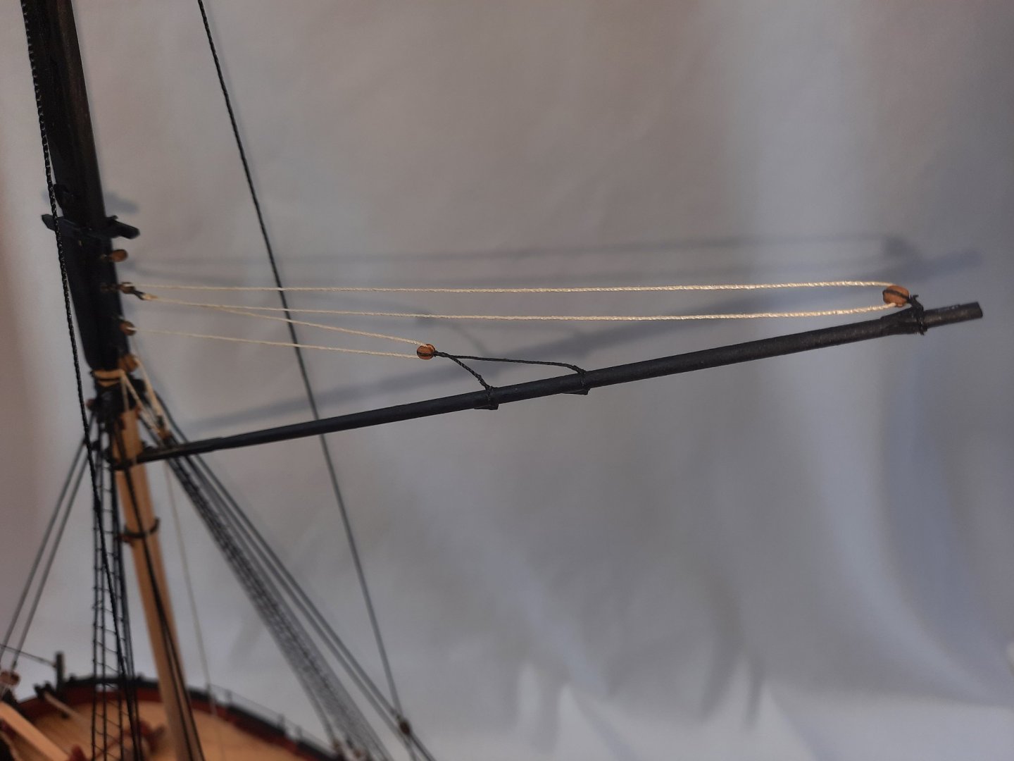
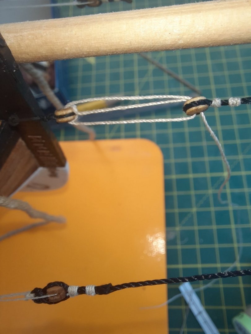
This was a much more straightforward task. The main boom lift was a simple rigging task, as shown below

Next the two lines from the end of the main boom were added, one was threaded through the block and one was added with a loop.
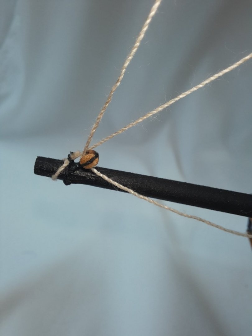
The line from the end block was then taken to the end of the driver boom, where it was fastened with a loop and the other thread was taken to the top block on the main mast.
A block was then added to the end of the thread.

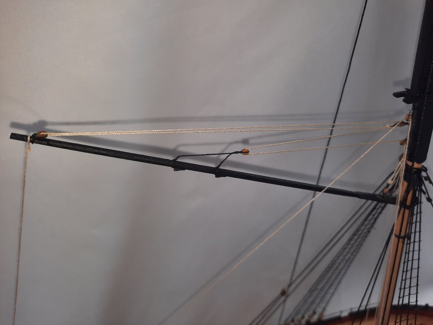
The line is then belayed as shown below. The thread is fed through another block which is hooked to an eyebolt on the channel back up and the returns, after being passed through the splitting block, to be belayed on the cleat located on top of the capping.

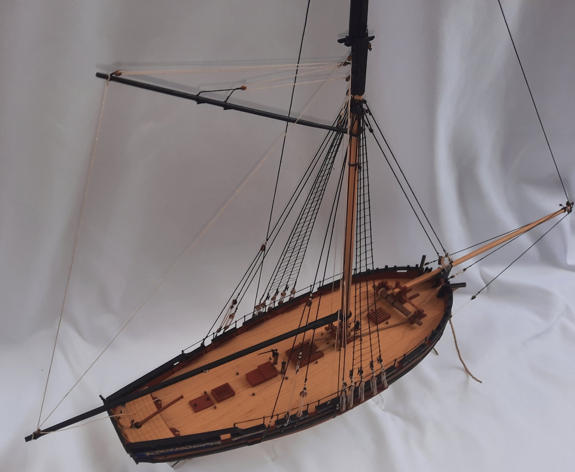
The completed driver and main boom rigging


-
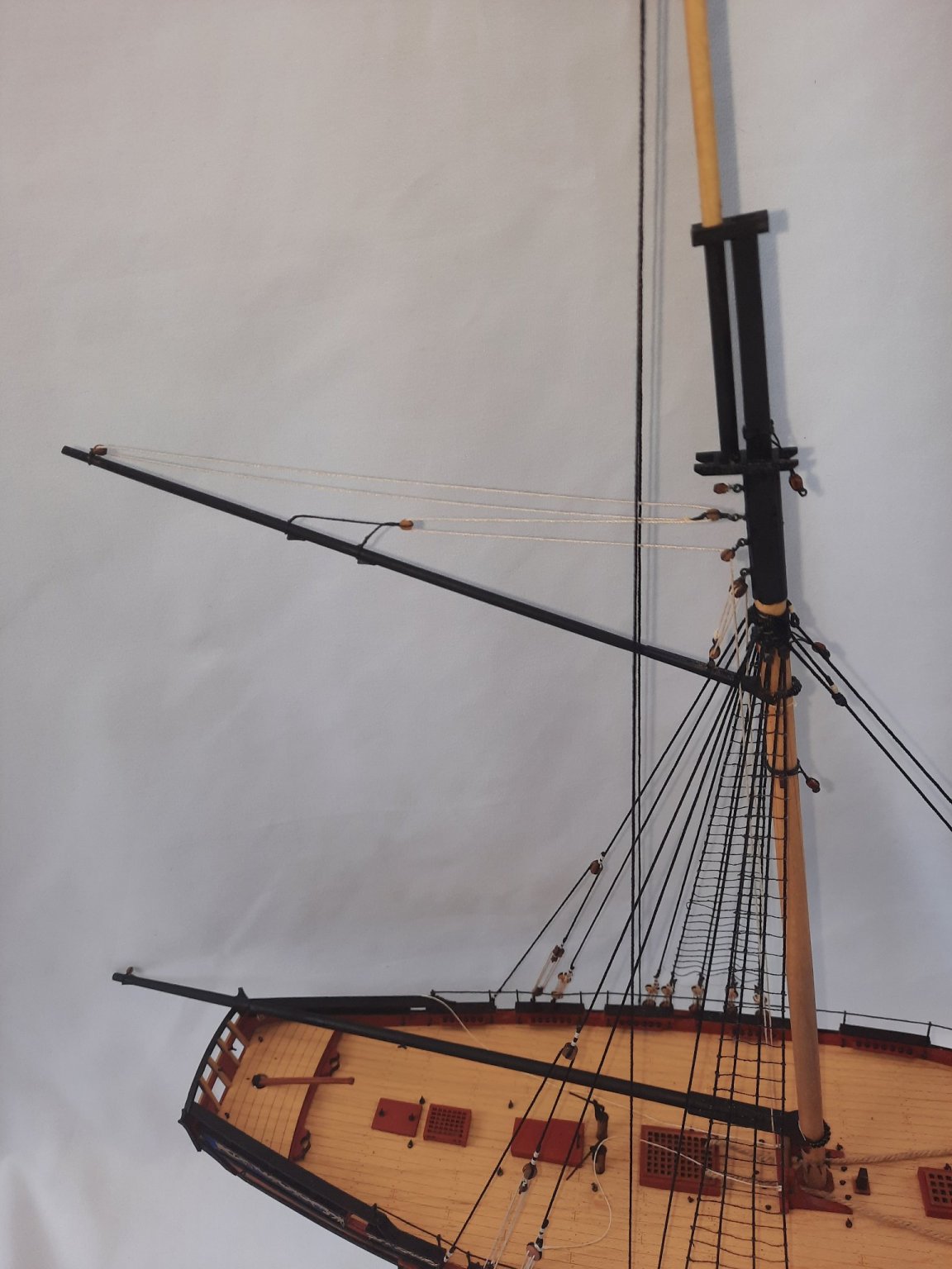
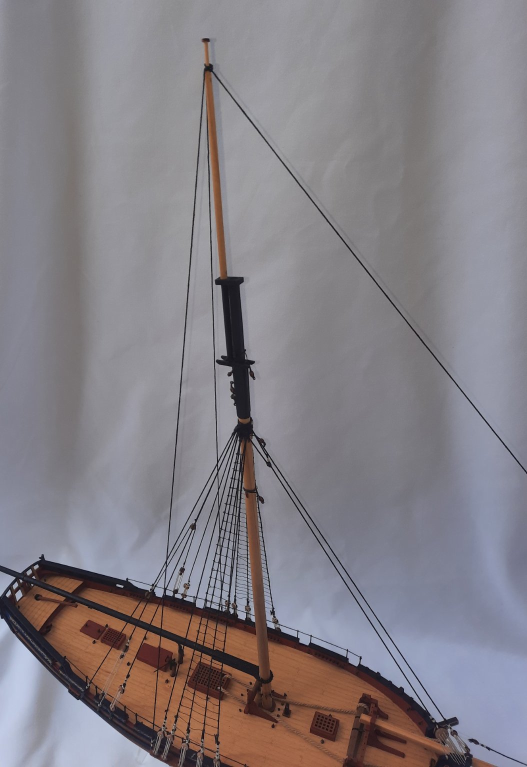
An easy rigging task today, which was adding the two back stays and single fore stay for the topmast.
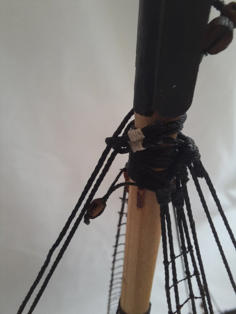
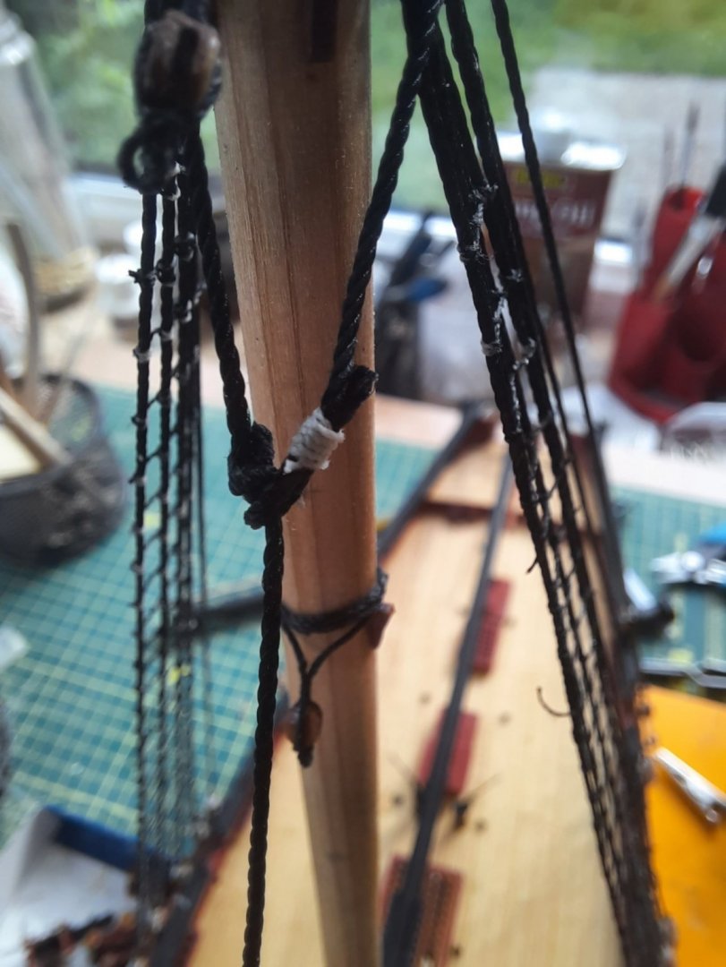
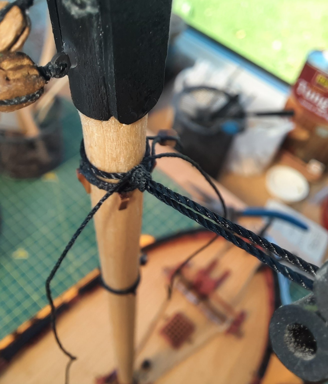
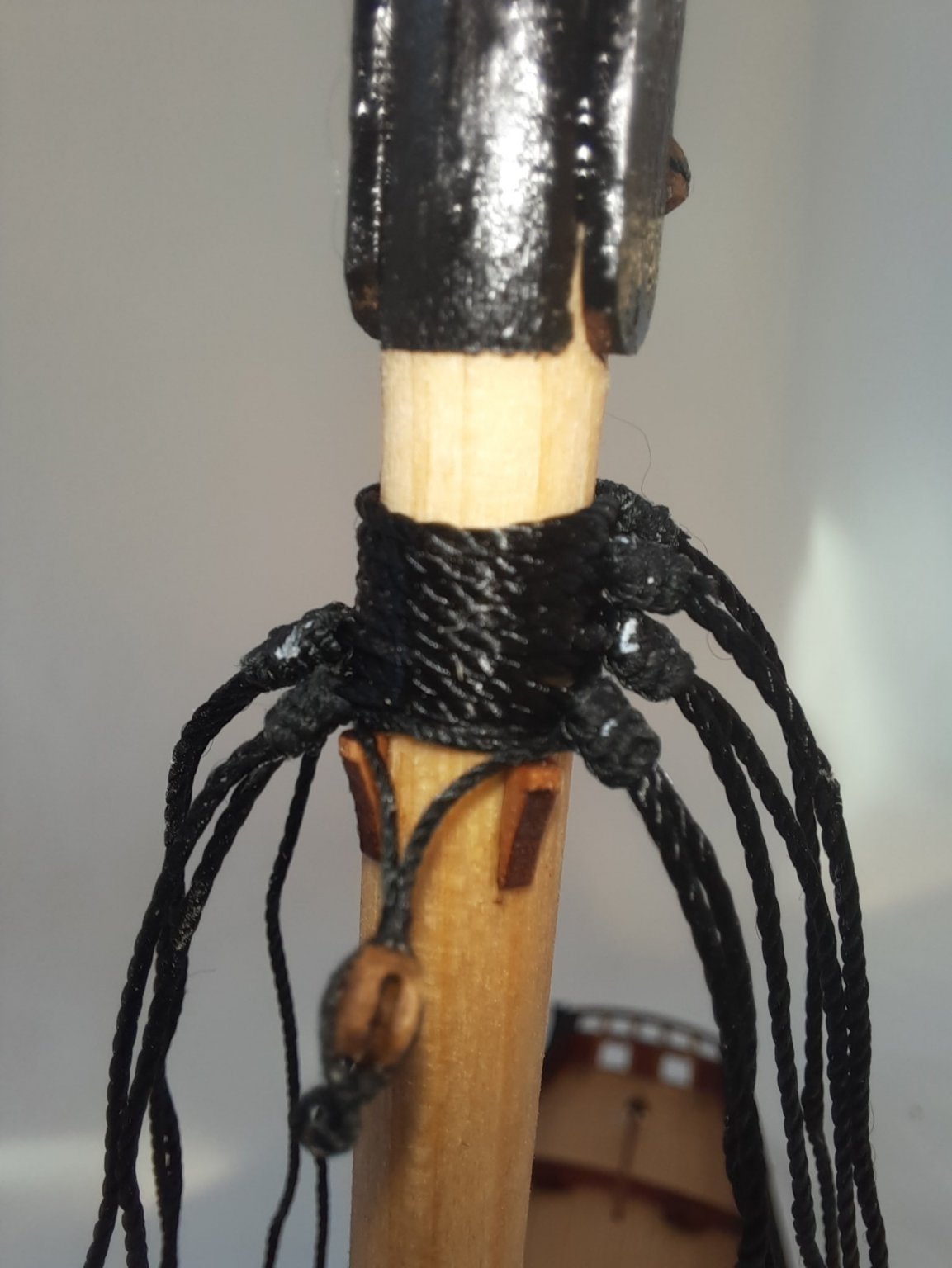
I started by cutting a single length of black thread for the two back stays and secured this thread (at it approx. mid point) to the topmast. I used a simple clove hitch knot which was then coated with a diluted pva solution to keep the knot tight and in place. Each end of the thread was then fed through their respective eyebolts and seized.
This is a photo of one of the eyebolts, not my best work at seizing
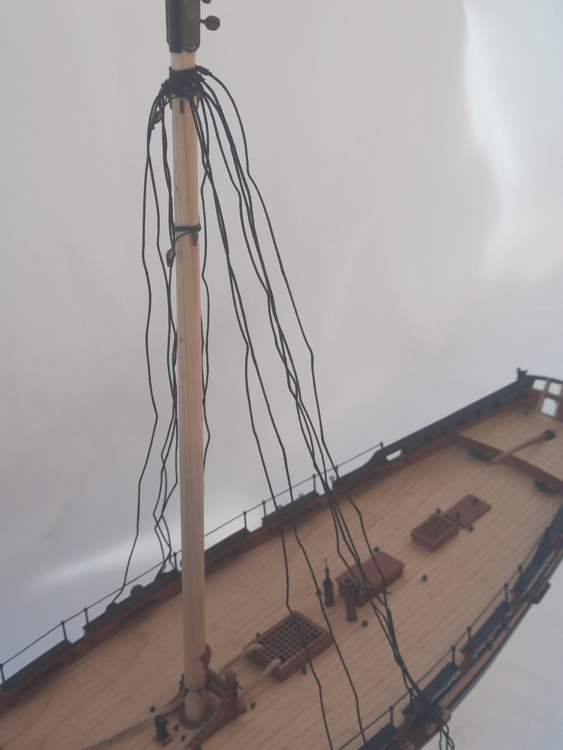
This photo shows the completed back stays. The topmast fore stay line has been added but not fully rigged at this stage.

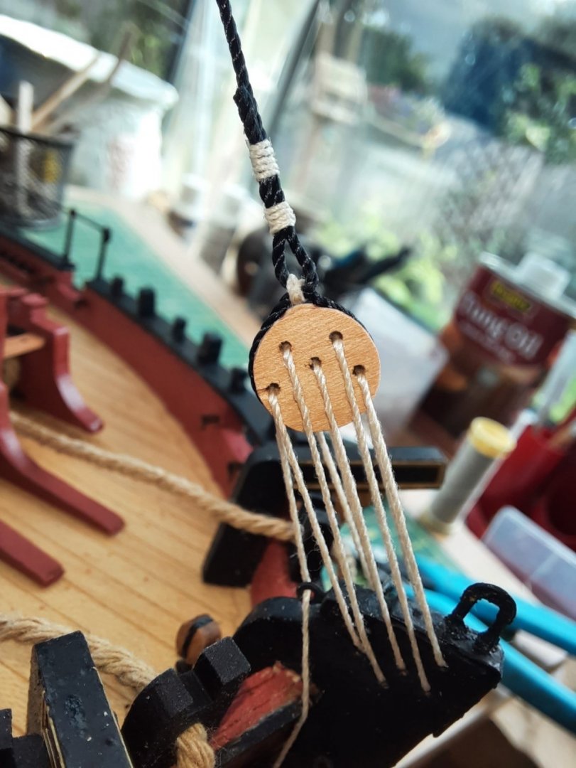
Moving on to the topmast forestay the thread has to pass through the centre hole on the triple block fitted to the end of the bowsprit. This turned out to be the most difficult aspect in terms of trying to get the thread to slide through the hole. I resorted to using a 0.9mm micro drill to enlarge the hole which did the trick.
The end of the topmast fore stay is then attached to the starboard side of the hull with a using a double thimble arrangement. The next photo shows this before I have completed running the thread through the two thimbles.
Finally a picture of the completed stays.
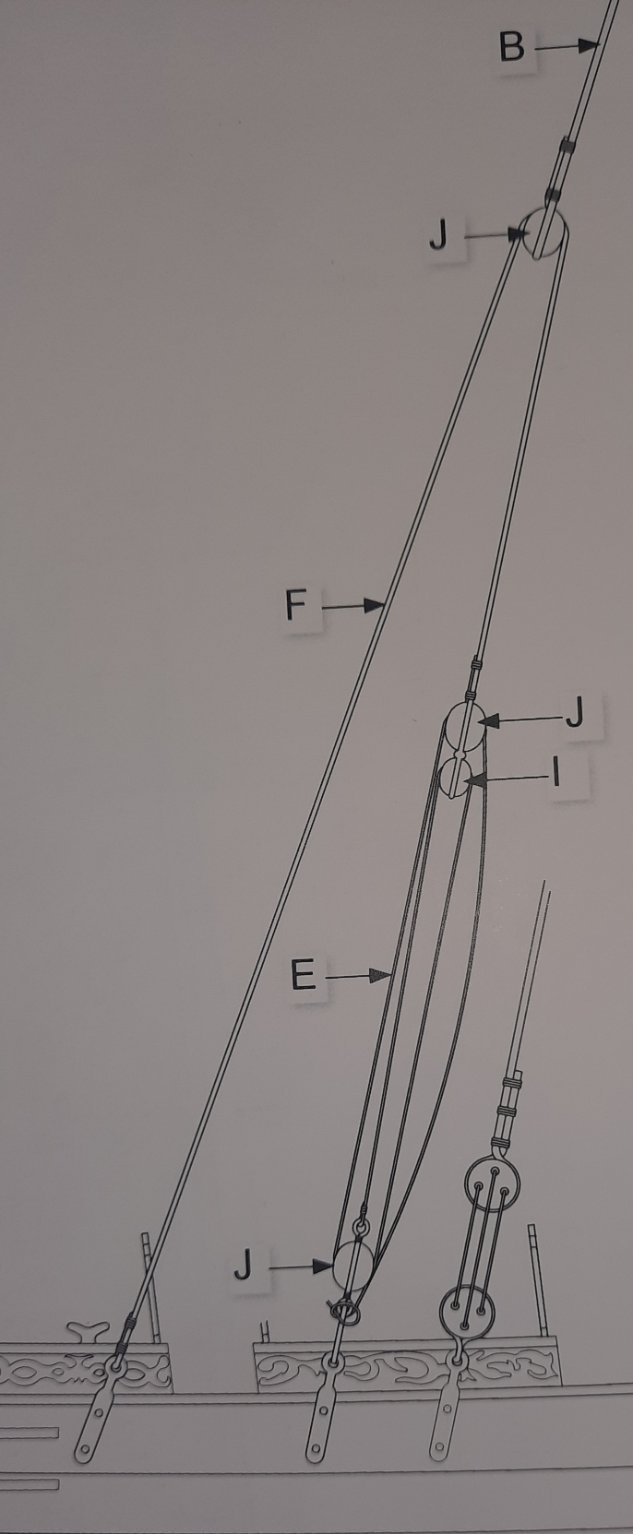
My next job will be to rig the main and driver booms. Having already studied the rigging plans I have decided that the driver boom needs to be rigged before the main boom.
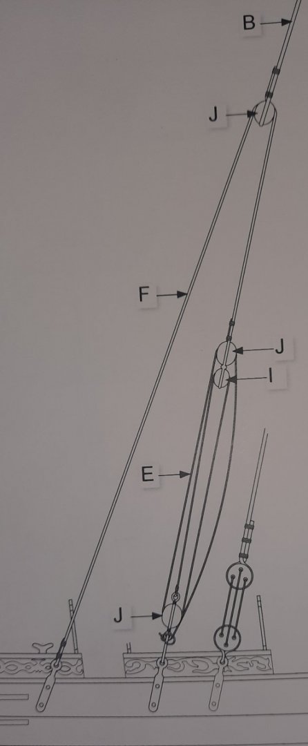
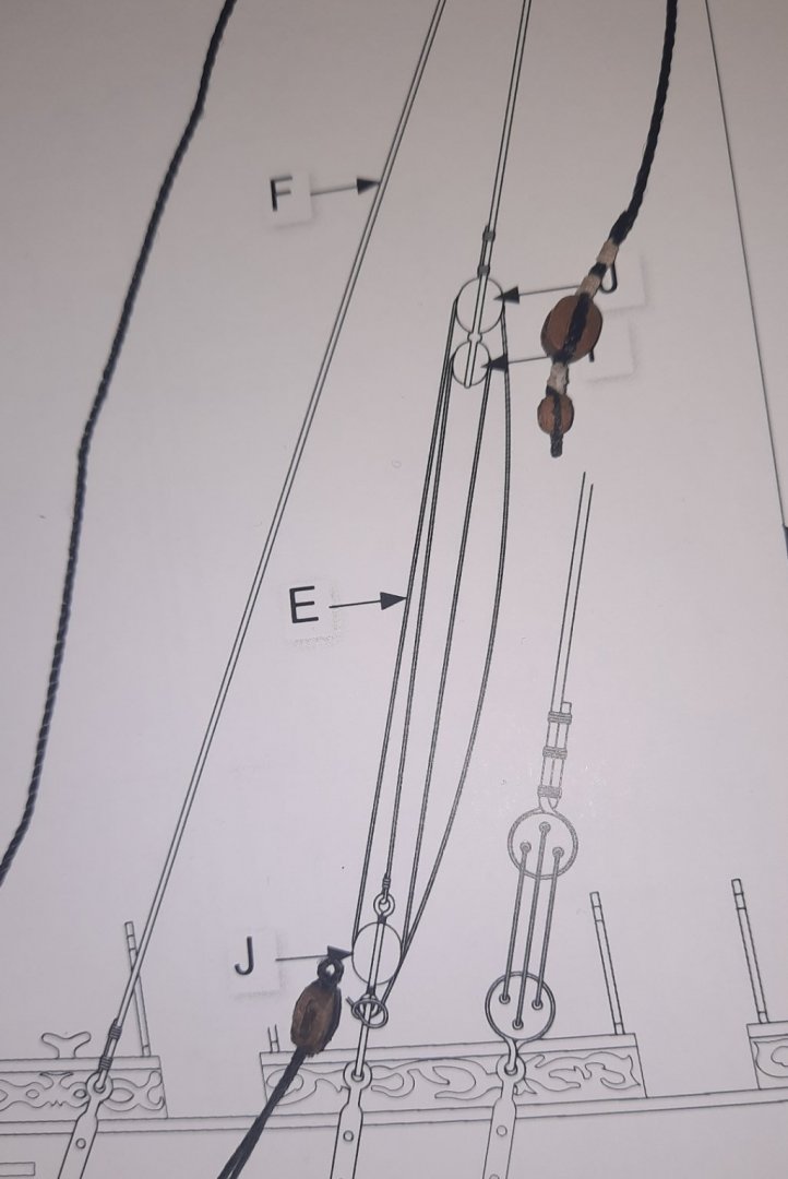
There are three main aspects to the driver boom rigging. The first to add the parrel beads so the driver boom can be attached to the main mast. Next the position of the driver boom on the mainmast will be set by adding the lift rigging. This is shown on the right hand side of the next photo and is a standard single and double block arrangement. Finally the rake of the driver boom is set by a thread that passes through 4 different blocks, 2 blocks on the main masts, 1 block at the mid point of the driver boom and 1 block at the end of the driver boom.
- PRS, DelF and GrandpaPhil
-
3
-
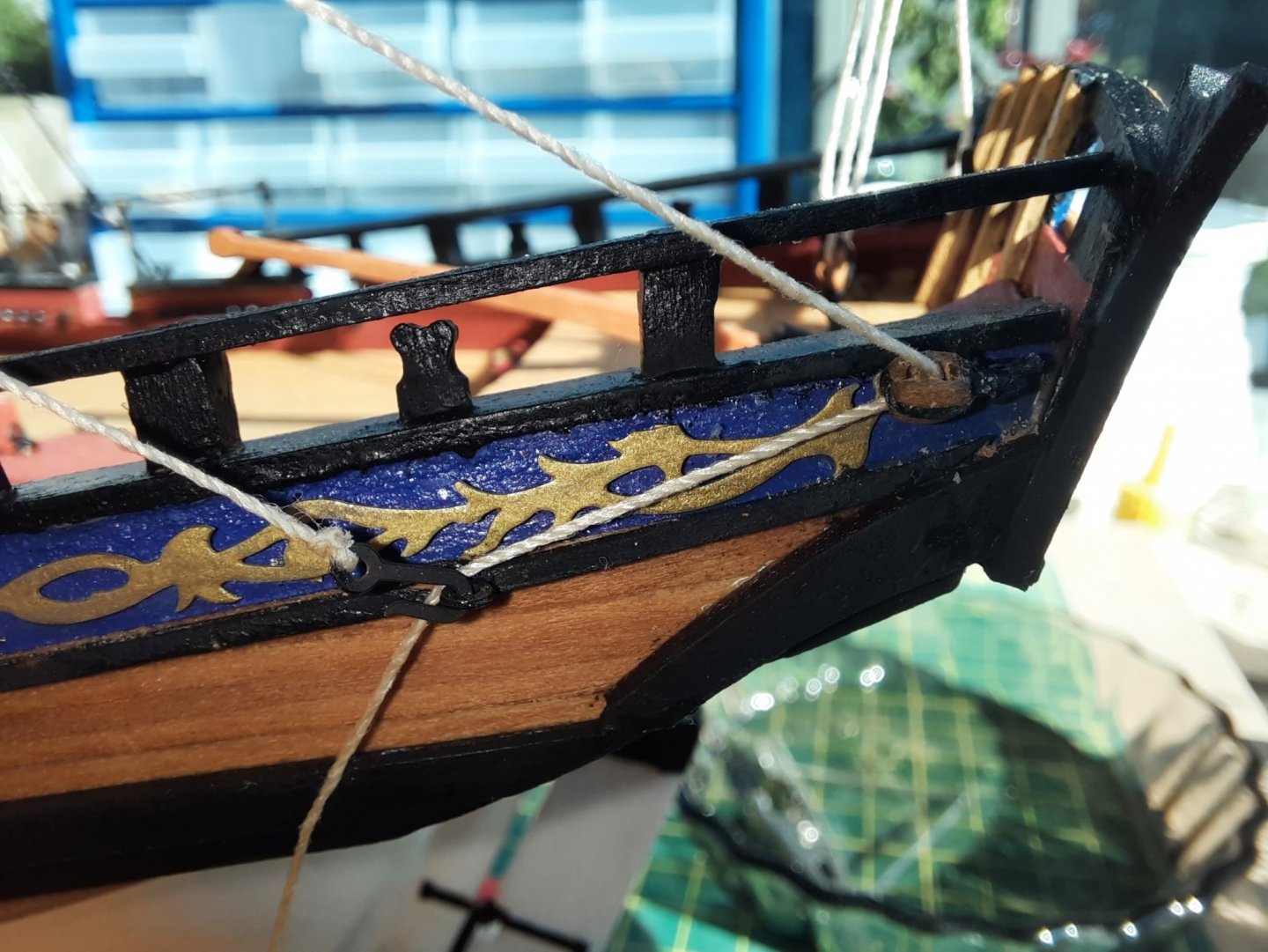
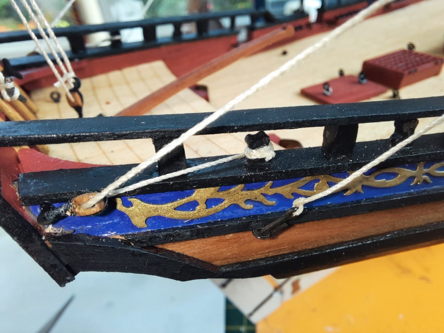
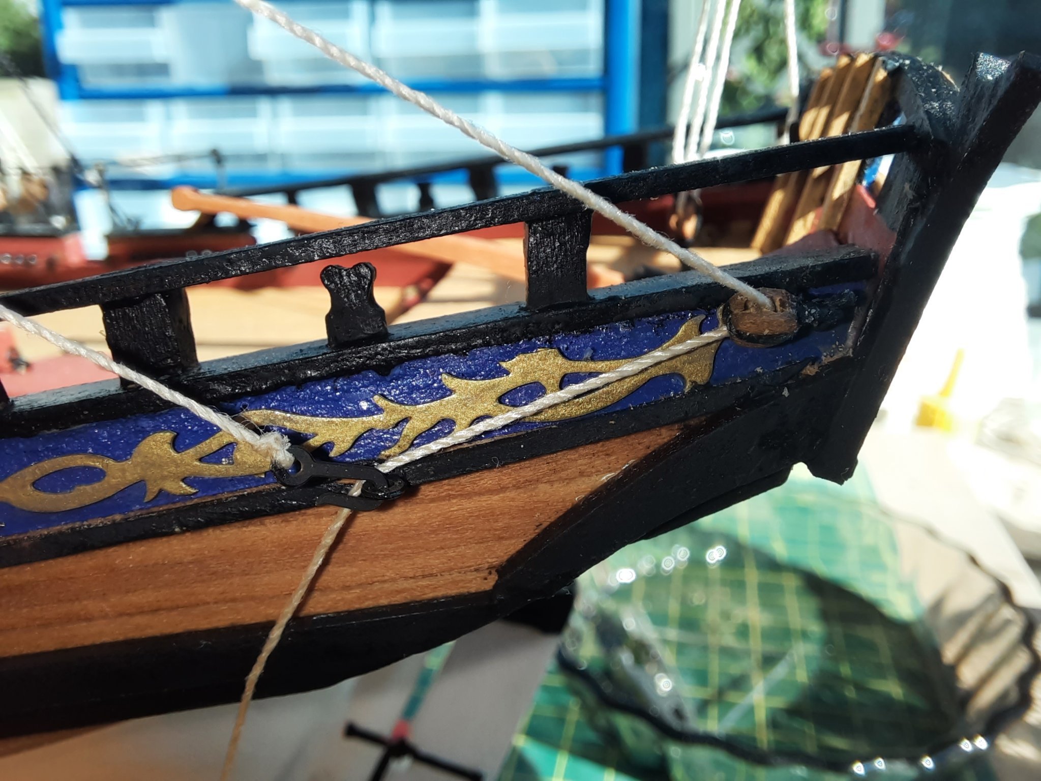
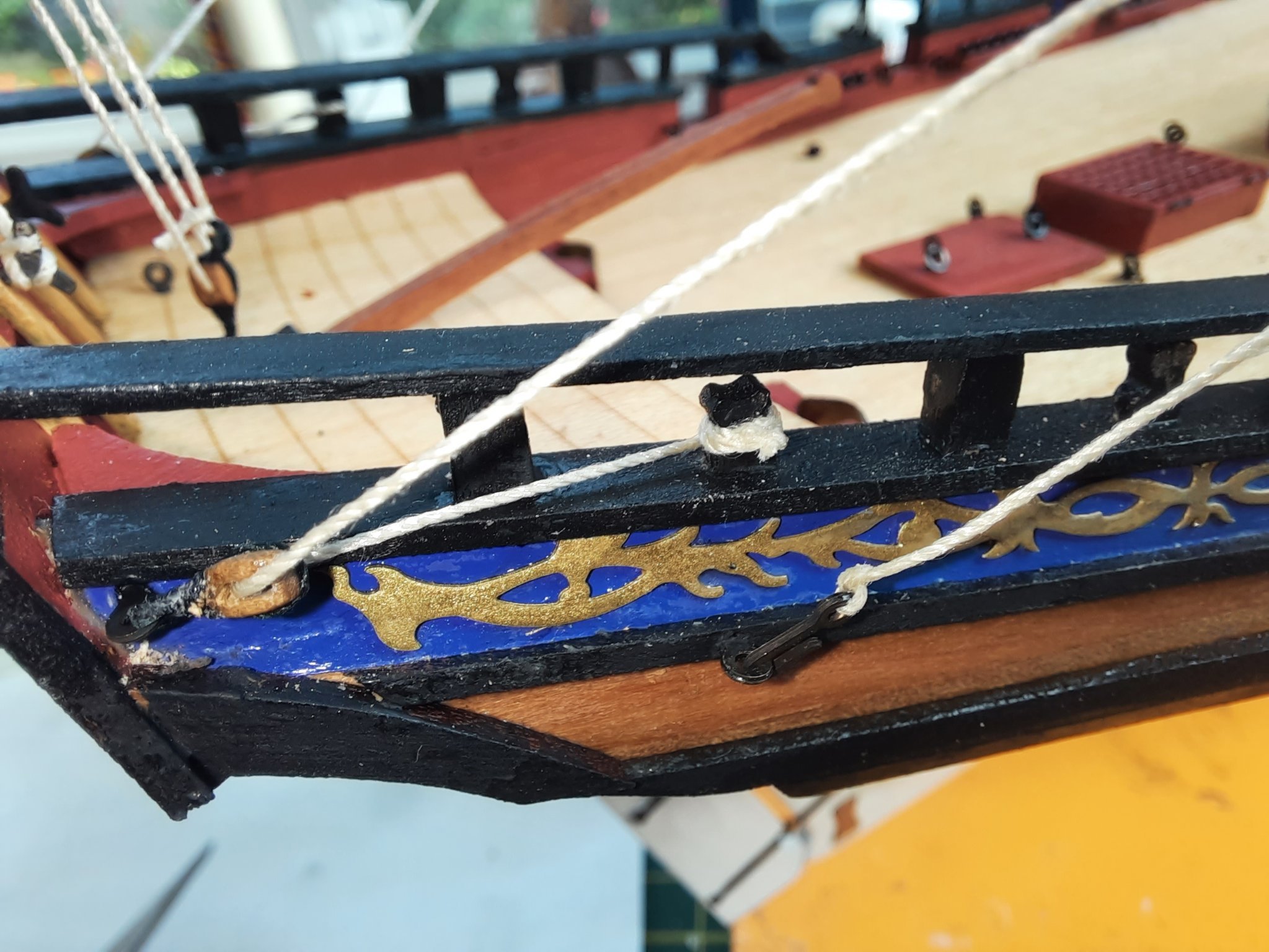
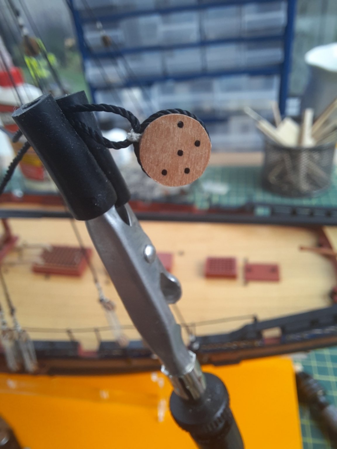
Today I thought I would detail the complete process I used for the start of the bowsprit rigging.
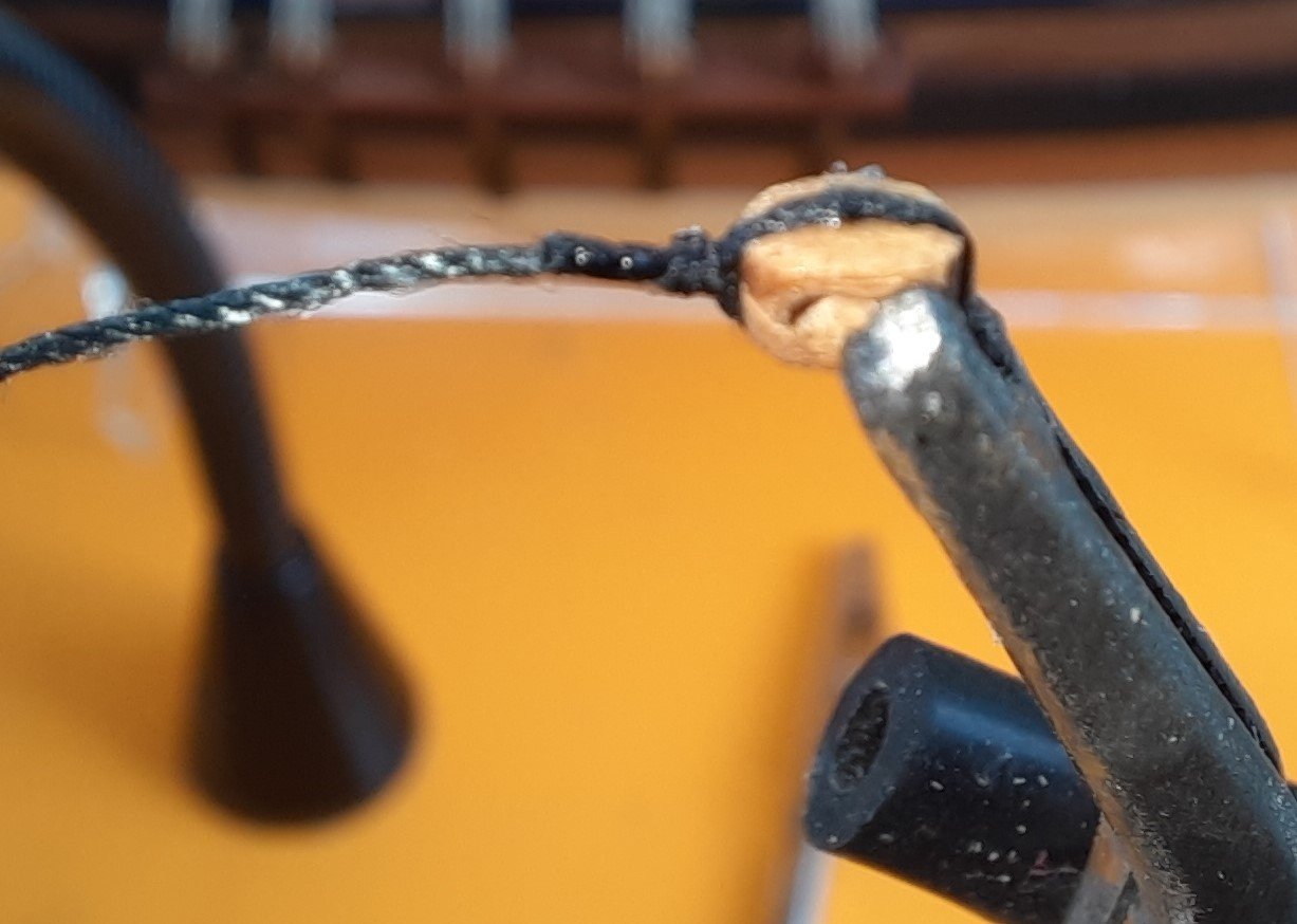
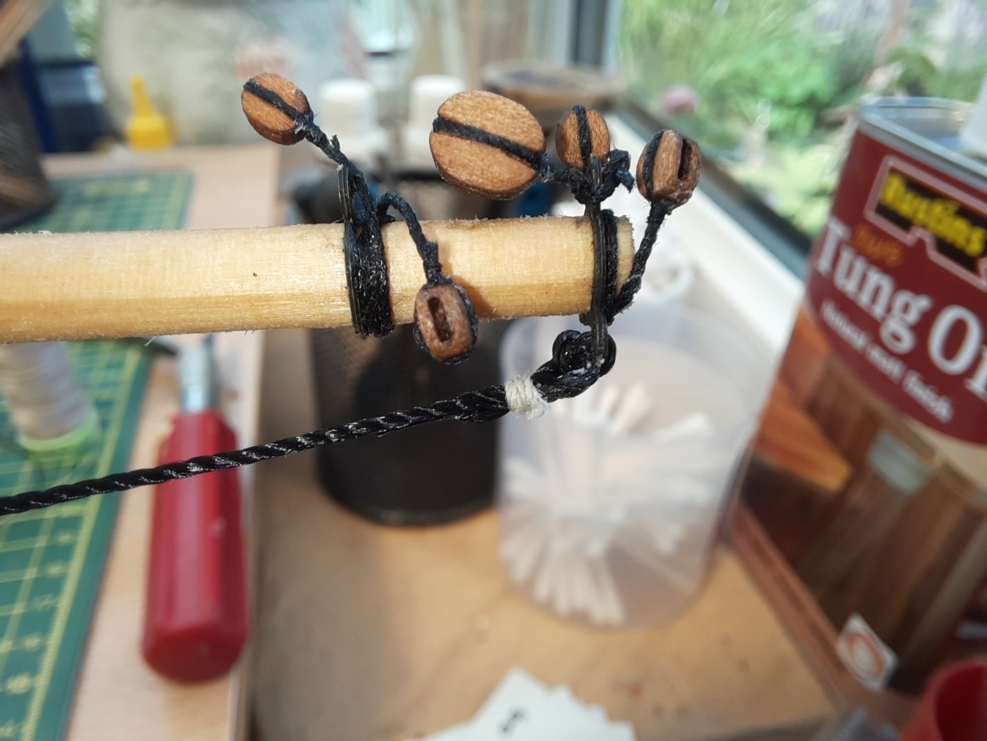
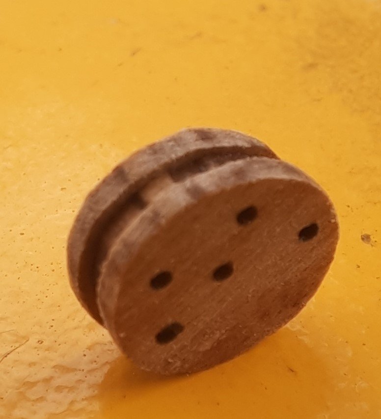
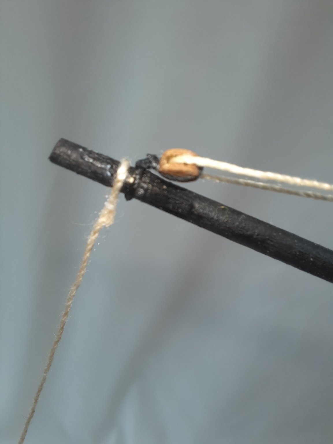
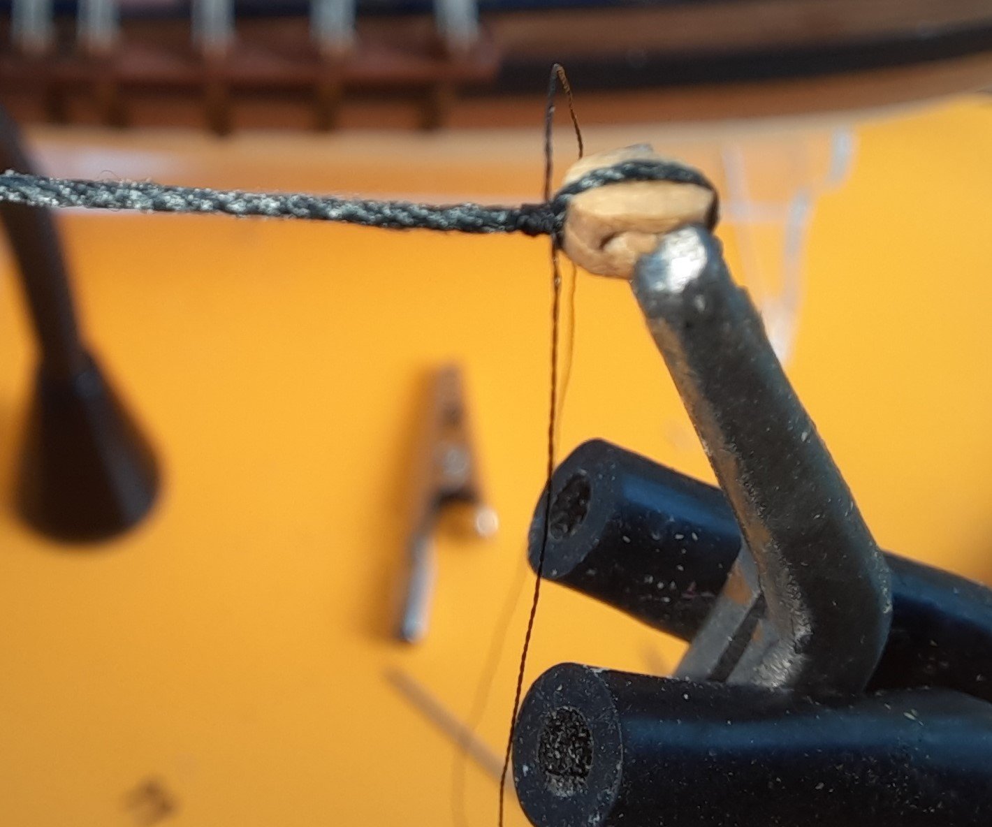
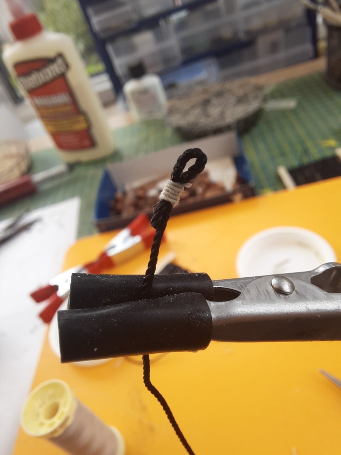
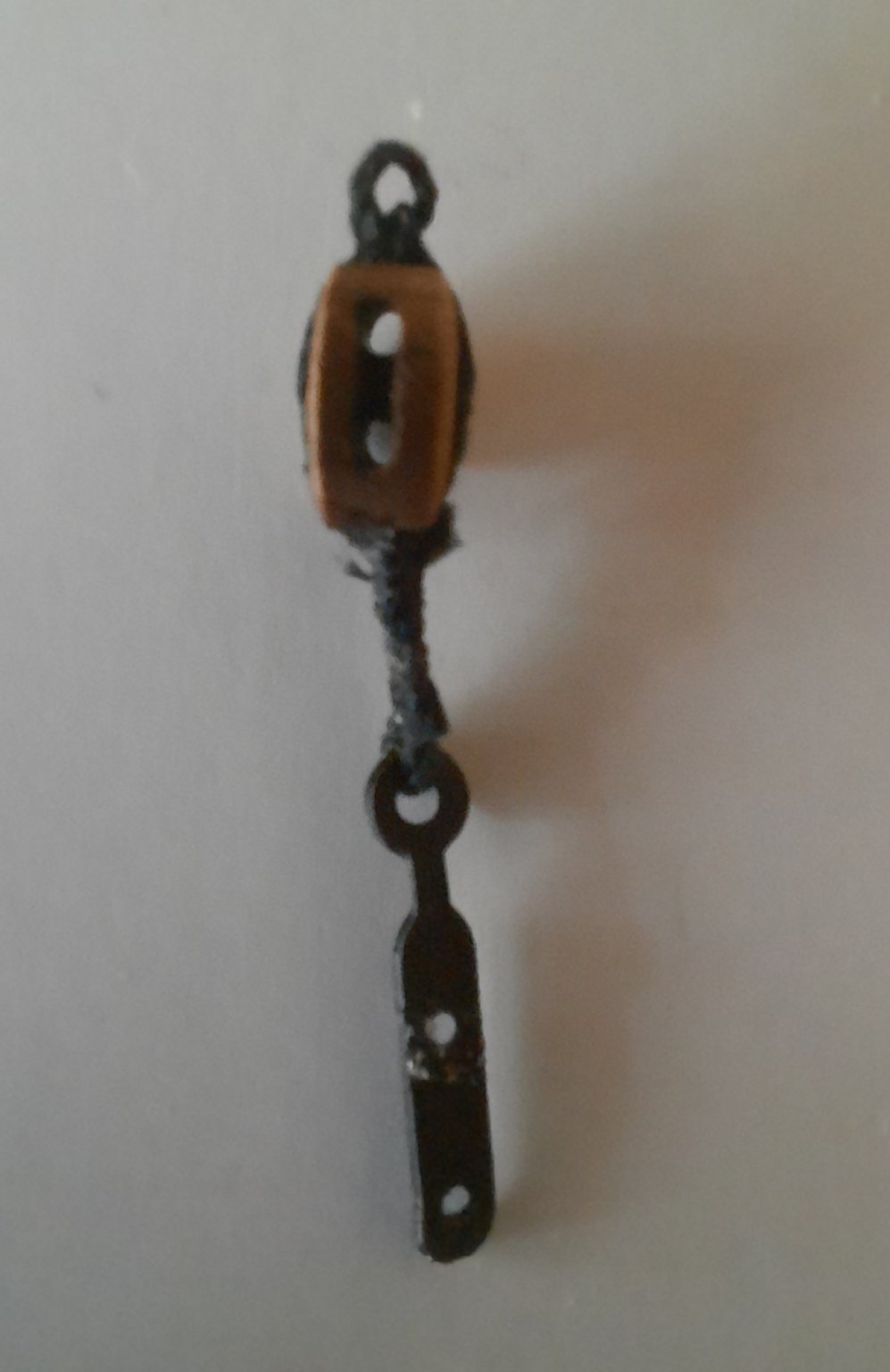
I always study the rigging plan to ensure I fully understand what is required and to then contemplate how best to implement. This is picture of the blocking arranging required for the task in hand on the bowsprit. There are two 3mm blocks required. The right hand one requires a loop end and the left hand one requires an eyebolt. I always find it better to fit the eyebolt to the block before fitting the eyebolt in place.
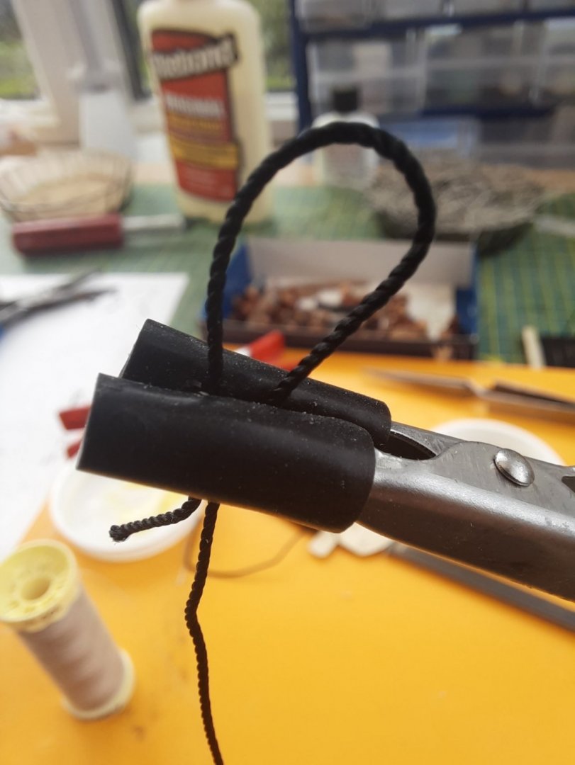
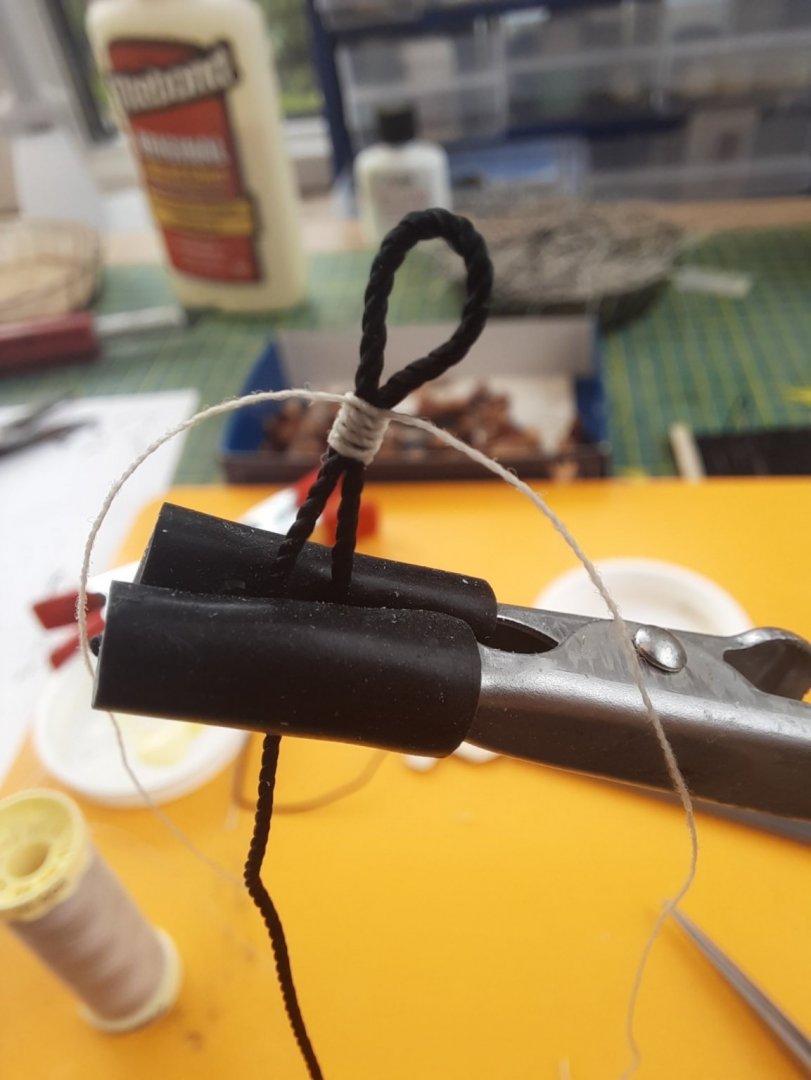
Using a length of 0.75mm black thread I formed the loop around a metal pin and used a standard reef knot to secure. Next 1 added a diluted pva wash on the loop to help ensure it retains its shape. With the loop formed the thread was then seized to a single 3mm block. Two seizing loops were shown on the plan sheet. I opted to use 0.1mm gutterman natural thread for the seizing. I use the alternate top and bottom half hitch knots method for the seizing. The photo below was taken after completion of the first seizing and I have just started to add the second seizing. I found it better to leave the metal pin in situ at this stage.
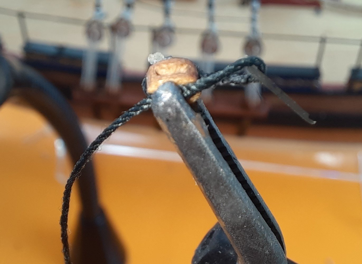
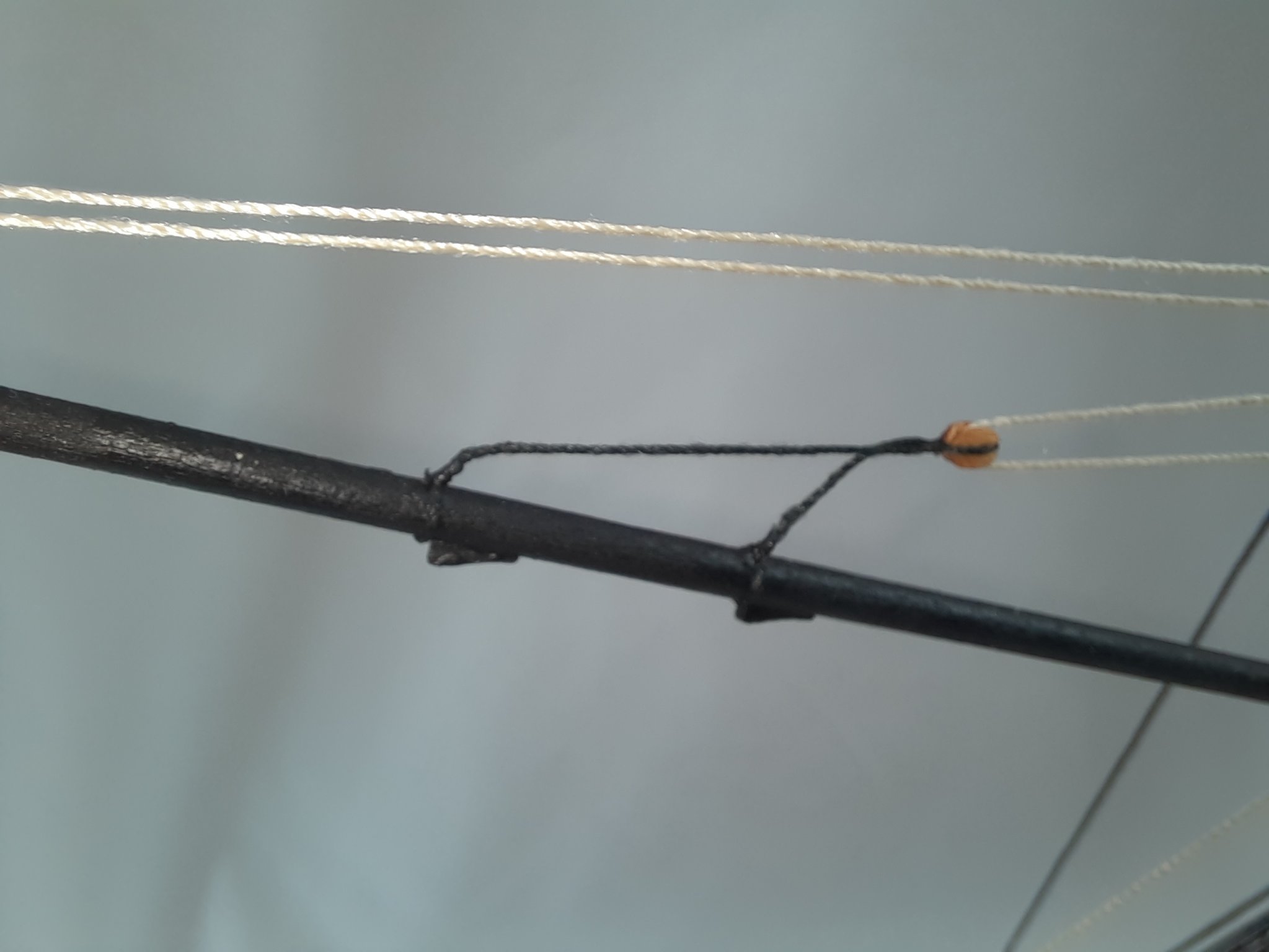
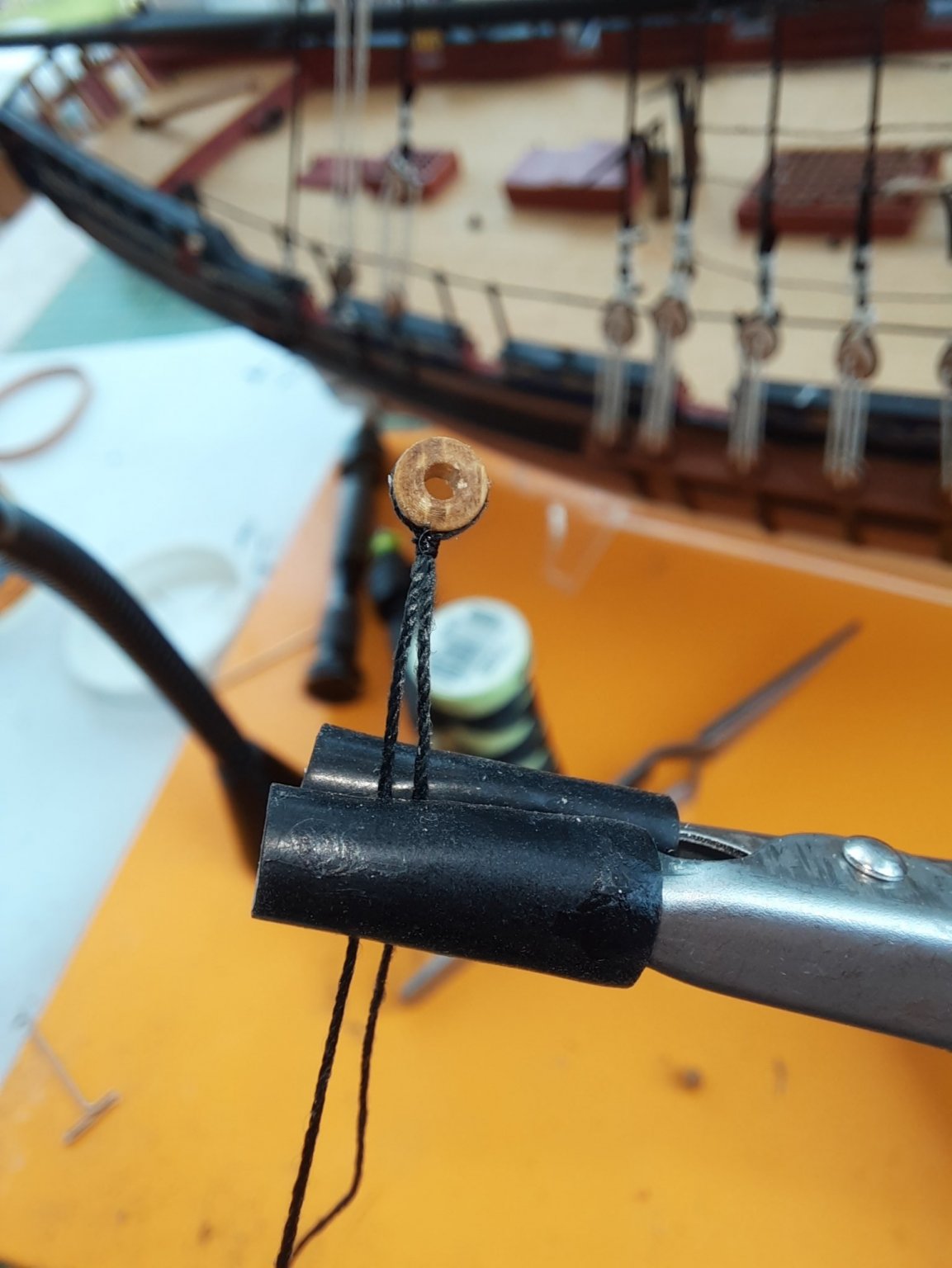
The next picture shows the completed block. The use of the quad hands for these types of tasks is without question a great time saver. Many thanks to @DelF for sharing this tool on his Speedy build log and for some of the rigging method outlined in this post which I have copied.

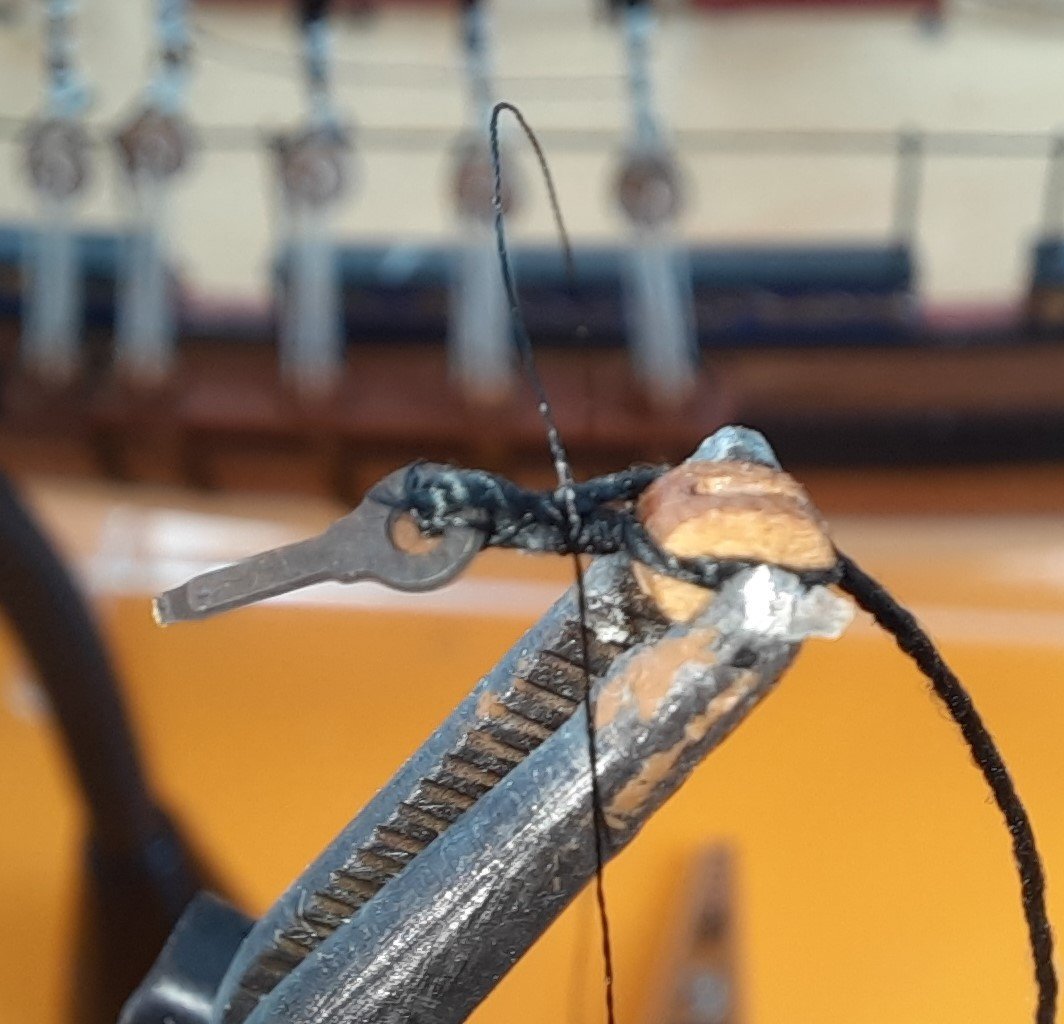
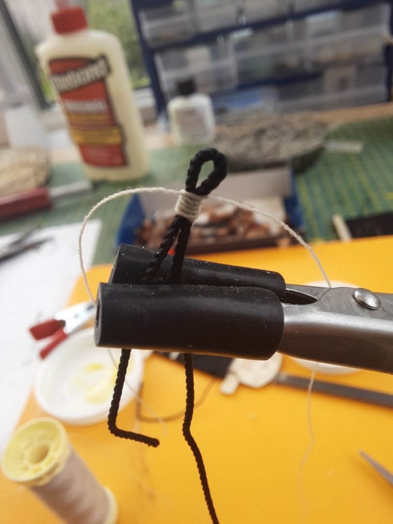
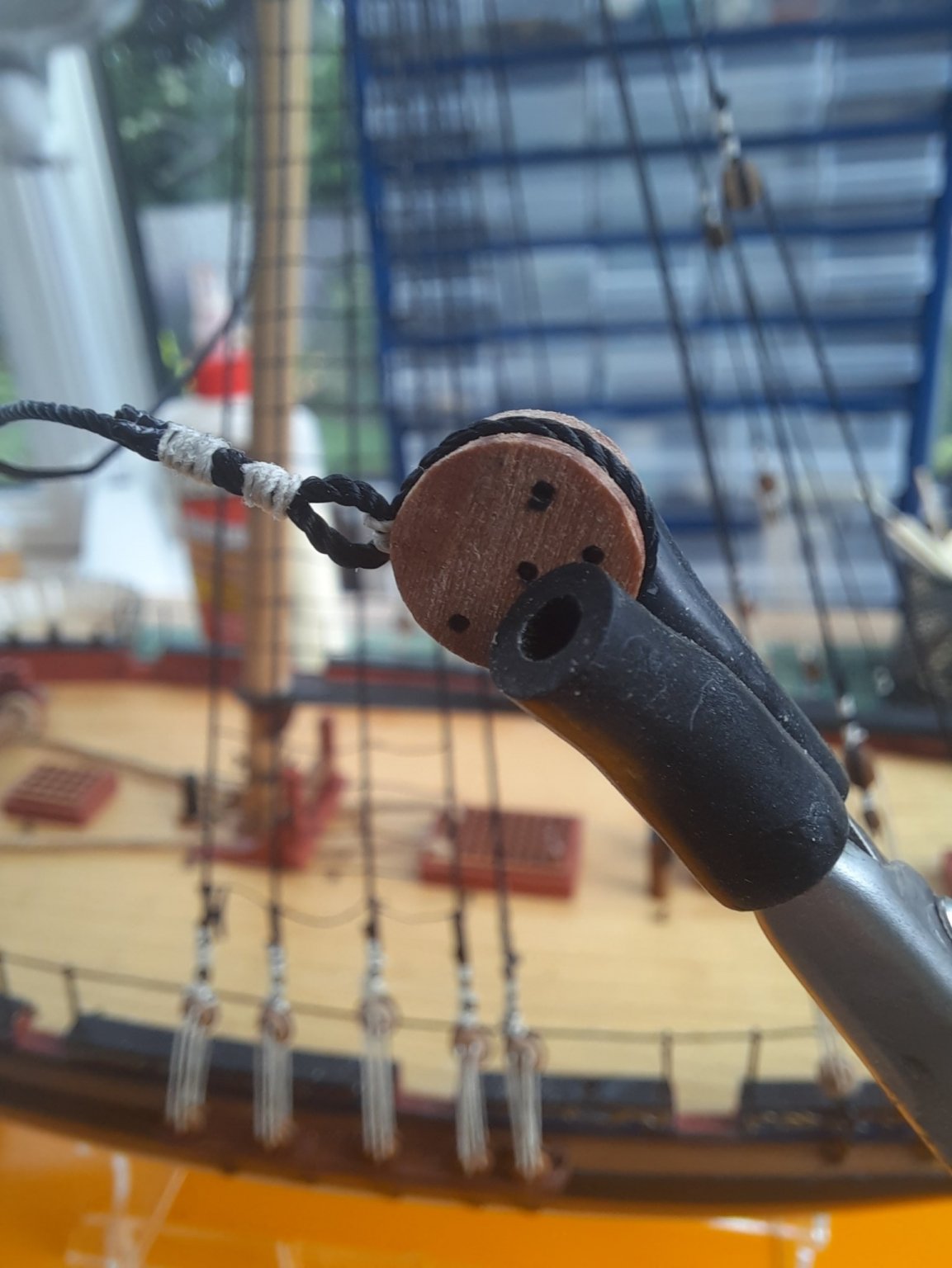
With the 2nd 3mm block held in the quad hands a short length of 0.25mm black thread was positioned around the block, as shown in the next photo.

Using the alternative half hitch knot method, with fly tying thread the block is soon seized
Next I cut off one of the two lengths which leaves the block with a single thread tail, as shown below.
Again coping something I had seen DELF do the thread tail is passed through the eyebolt and then clamped to the side of the block, as shown below.
Using black fly tying thread the eyebolt is seized to the block, and the picture below shows the start of this process.
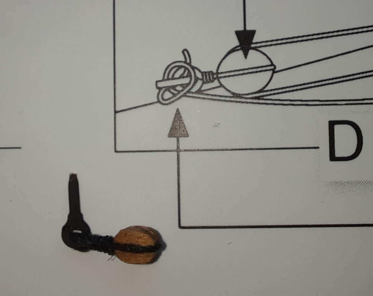
Using the alternate half hitch knot method the job is soon completed, and a quick check shows it looks something like the plan.
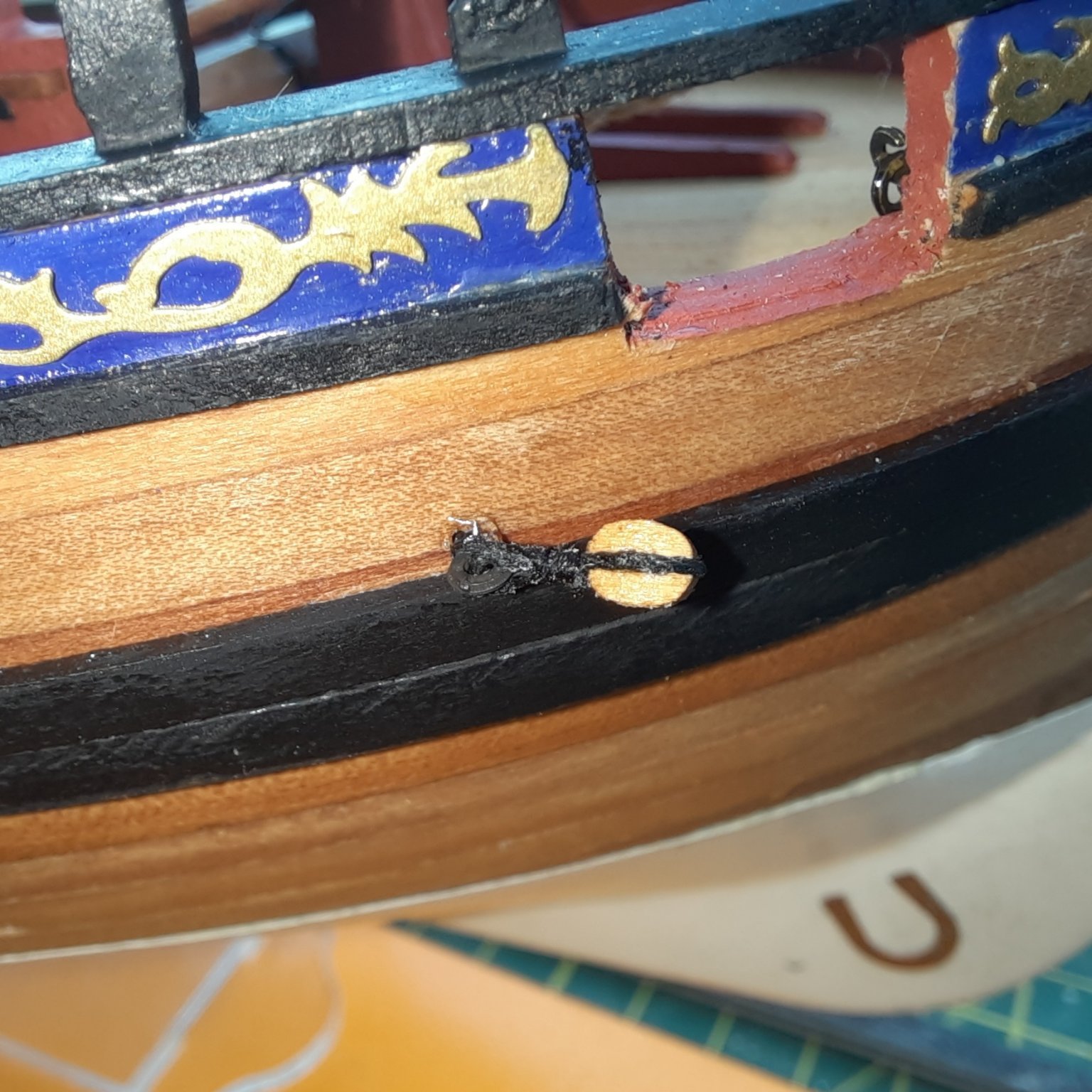
A touch of ca gel was then applied to the eyebolt before it was fixed in place on the hull.
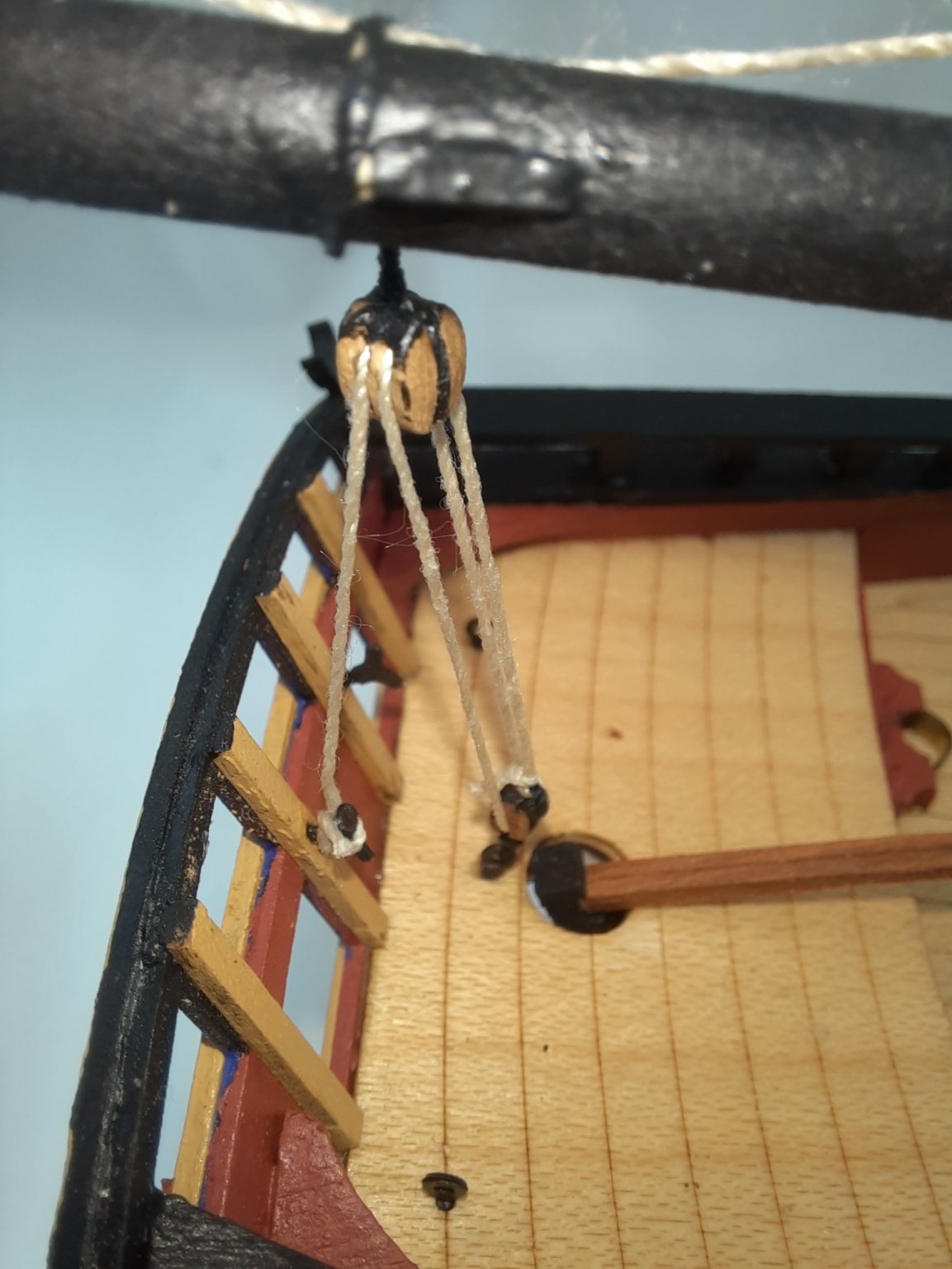
The other block thread end has now fastened to the end of the bowsprit.
With both blocks in place the last task is to add the 0.1mm natural thread rigging. This is shown in the next photo. The free end of the thread just requires belaying to the eyebolt, as was shown in the first photo in this post. I will do this once I have repeated the process for the post side.
-
Lower Forestay Part 2
Following on from my previous post earlier today I have now added the second lower forestay.
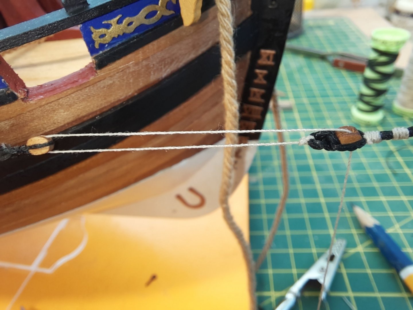
This is a picture of the one of the thimble seized to the thread before it is secured to the stempost U eyebolt.

I made a loop in the 0.25mm natural thread and then started to rig it between the two thimbles.

A close up of the completed thimble rigging. I tied the loose end to the stempost ‘U’ shaped eyebolt.

A picture of the completed forestays

I have now added the bowsprit which is ready to be rigged, which will be my next task.

-
Lower Forestay
There are two forestays, the lower one is 1mm black thread and terminates at the bow via a deadeye. The other one is 0.75mm black thread and is terminated at the bow using two thimbles.
The first task is to make the deadeye from three pieces. To ensure the parts line up I used some pins to align the parts.
The parts were glued and clamped which resulted in a completed deadeye
The next task is to make the loops in the forestays. For this task I used my quad hands.
Using a series of alternate half hitch knots I started to seize the loop. I was not to worried about the size of the loop as I can pull the free end to close the loop up
I have now pulled the loose end to get the required loop size.
This is the completed loop

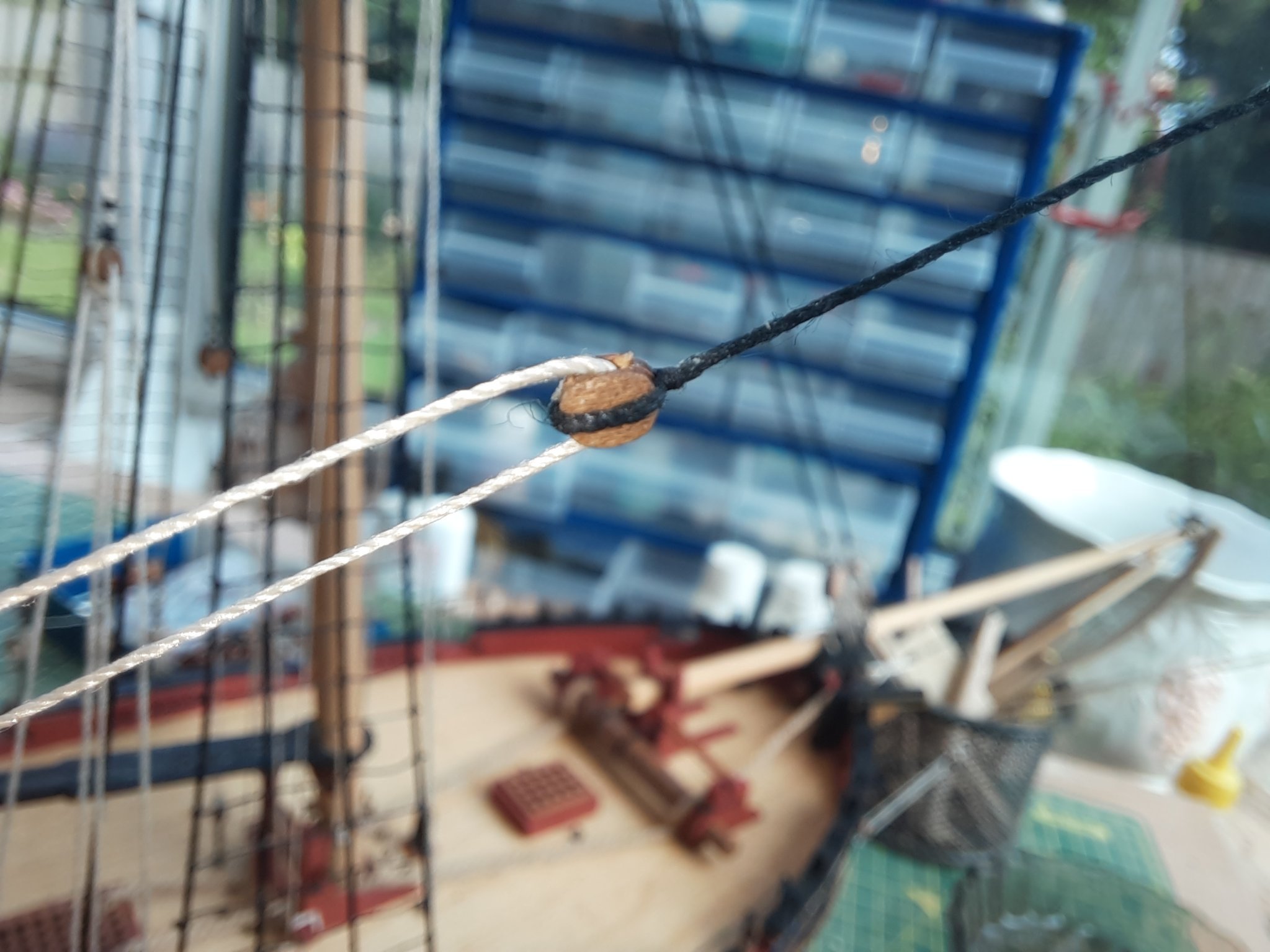
The two fore stays are placed around the main mast. The lower stay will require a mouse to set the position of the loop.
This picture gives an idea of how the stays will look

I have now added a mouse. I simply used some 0.25mm black thread and some half hitch knots
Next task is to add the deadeye, this is the picture of the deadeye fitted to the stay line

The next picture is the completed lower forestay / deadeye.

The final task is to add the lanyard, as shown below. The end had been fed through the eyebolt and is ready to be tied off once the lanyard has been adjusted.
- drjeckl, BLACK VIKING, Oboship and 1 other
-
4
-
-
I have now added the back stays. This should have been an easier task than I decided to make it. In the first instance I think it would have made life easier if I had not pre fitted the backstay iron plates. After much huffing and puffing I ended up removing both the middle backstay iron plates. Secondly, despite my best efforts, I developed an inane ability to wrap the back stay lines around the other back stay lines without noticing so I lost count of the number of times I had to redo bits to untangle the lines.
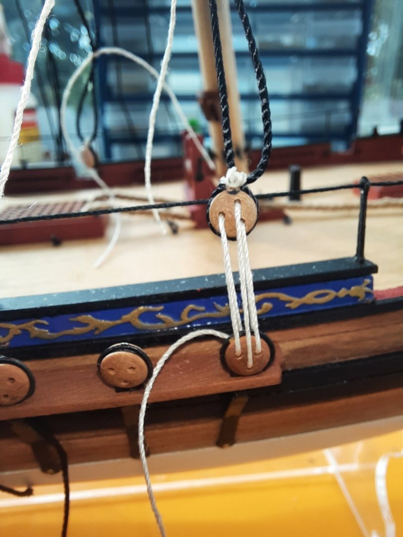
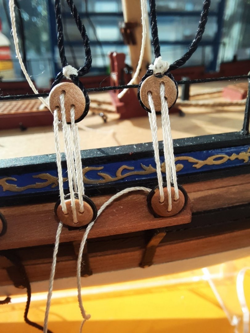
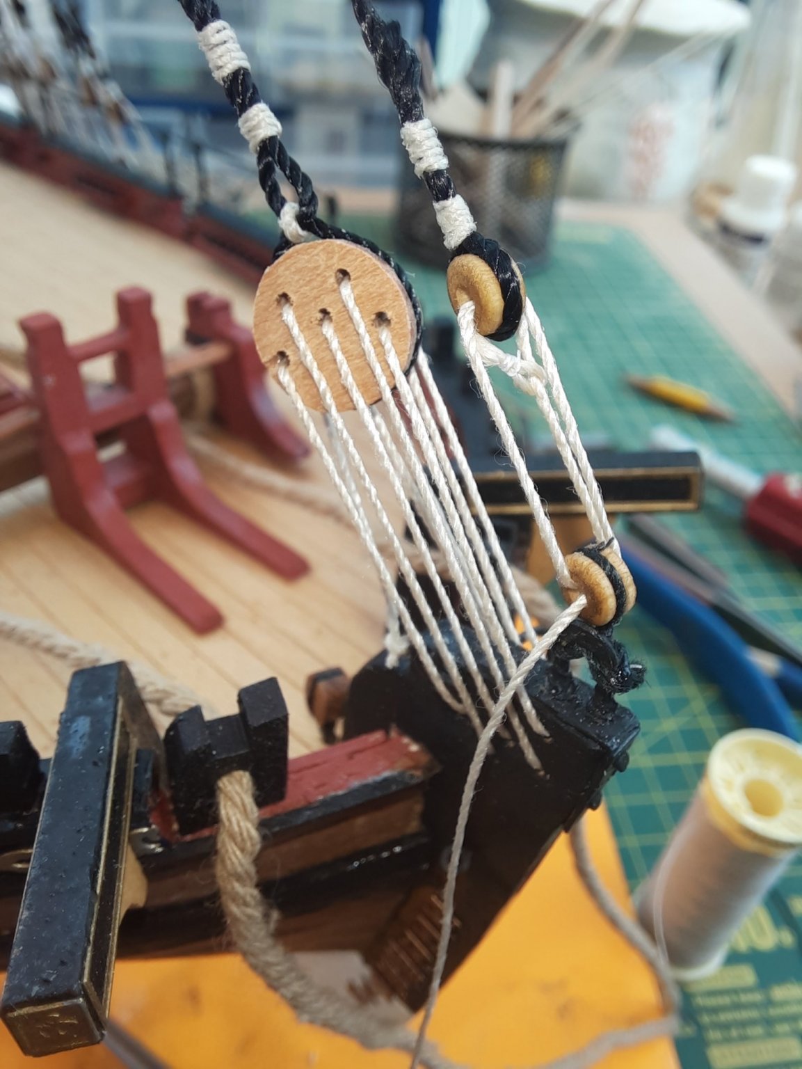
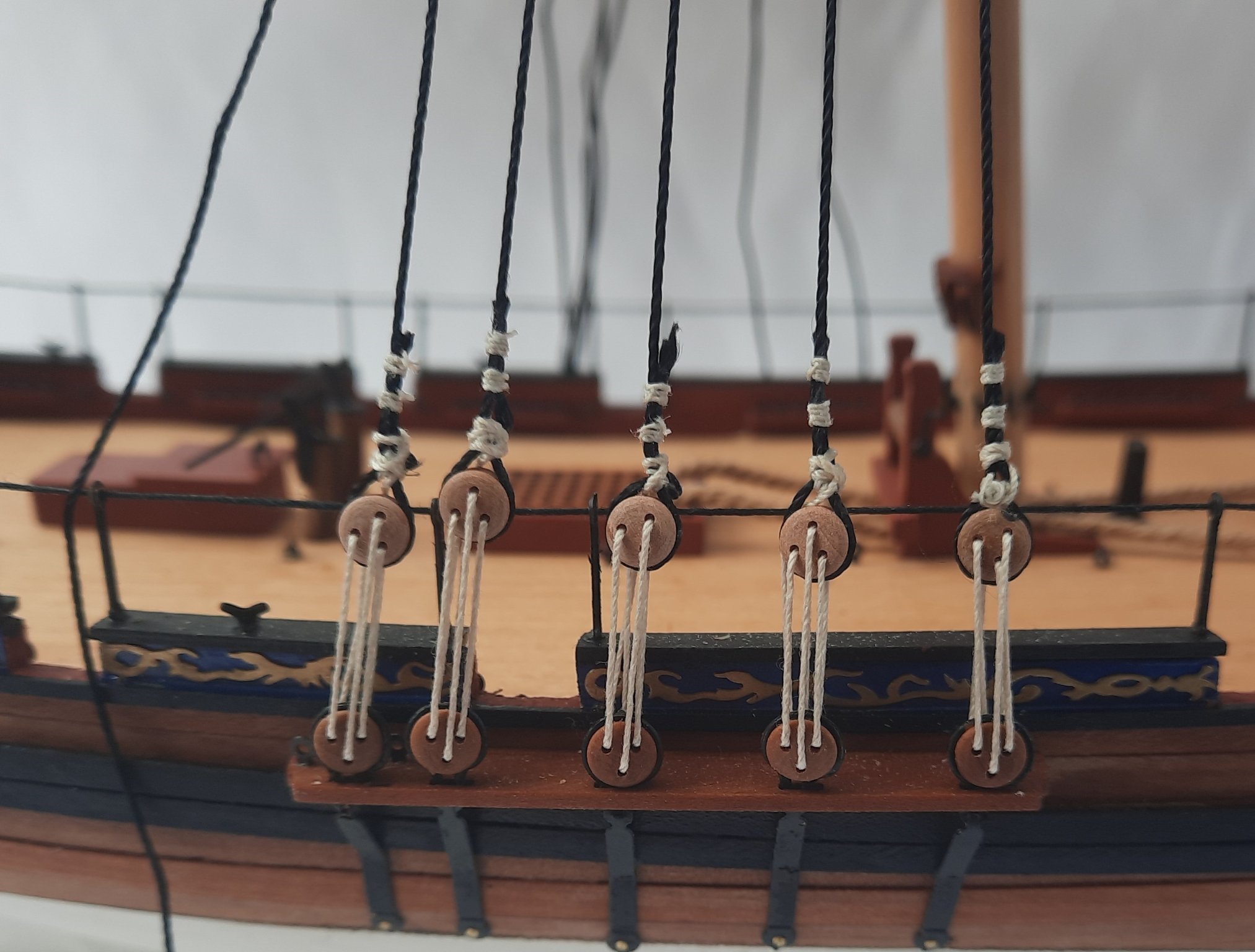
As shown on my previous post the two back stay lines were already secured to the main mast using 0.75mm black thread with a single 5mm block seized to the end. Each 5mm block needs to be rigged to the back two backstay iron plates using 2 x 5mm block and 1 x 3mm block per stay, as shown in the first photo.
Following the plan sheet I seized the various blocks to the required threads. As always I used my tried and trusted top and bottom half hitch method. The threaded eyelets were formed around a 0.8mm metal rod using a standard reef knot. The eyelet was coated with a diluted pva solution to help ensure it retains its shape.
I found it much better to secure the 5mm block to the middle backstay iron plate prior to fitting to it to the hull,

A single 5mm and single 3mm block were seized together to form a block pair. To do this I started with seizing the 5mm block, leaving the thread so the 3mm block could be seized. I finished the assembly off by whipping some thread between the two blocks.

I started the rigging process by threading the 0.25mm natural thread through the block arrangements. I then attached the backstay iron plate back to the hull. Next the 0.5mm black thread was fed through the top 5mm block and secured to the rear backstay iron plate. This is shown in the next photo where I am about to add the seizing to secure the thread to the rear backstay iron plate.

Once the rear backstay iron plate was complete I adjusted the 0.25mm natural thread rigging and once I was happy I held it in place with a pair of reverse action tweezers for a quick photo.
The final loose thread was then tied off around the middle backstay iron plate and the Cutter Alert was sent back for another photo. What cant be seen in this photo is the upper stay line is wrapped around the other back stay line. The easiest solution was to remove the deadeye lanyards to untangle.

I then repeated the process for the other stay and the completed back stay rigging is shown below
I plan to add the two forestays next before moving on to the bowsprit.
- Oboship, Freezing Parrot, drjeckl and 1 other
-
4
-
-
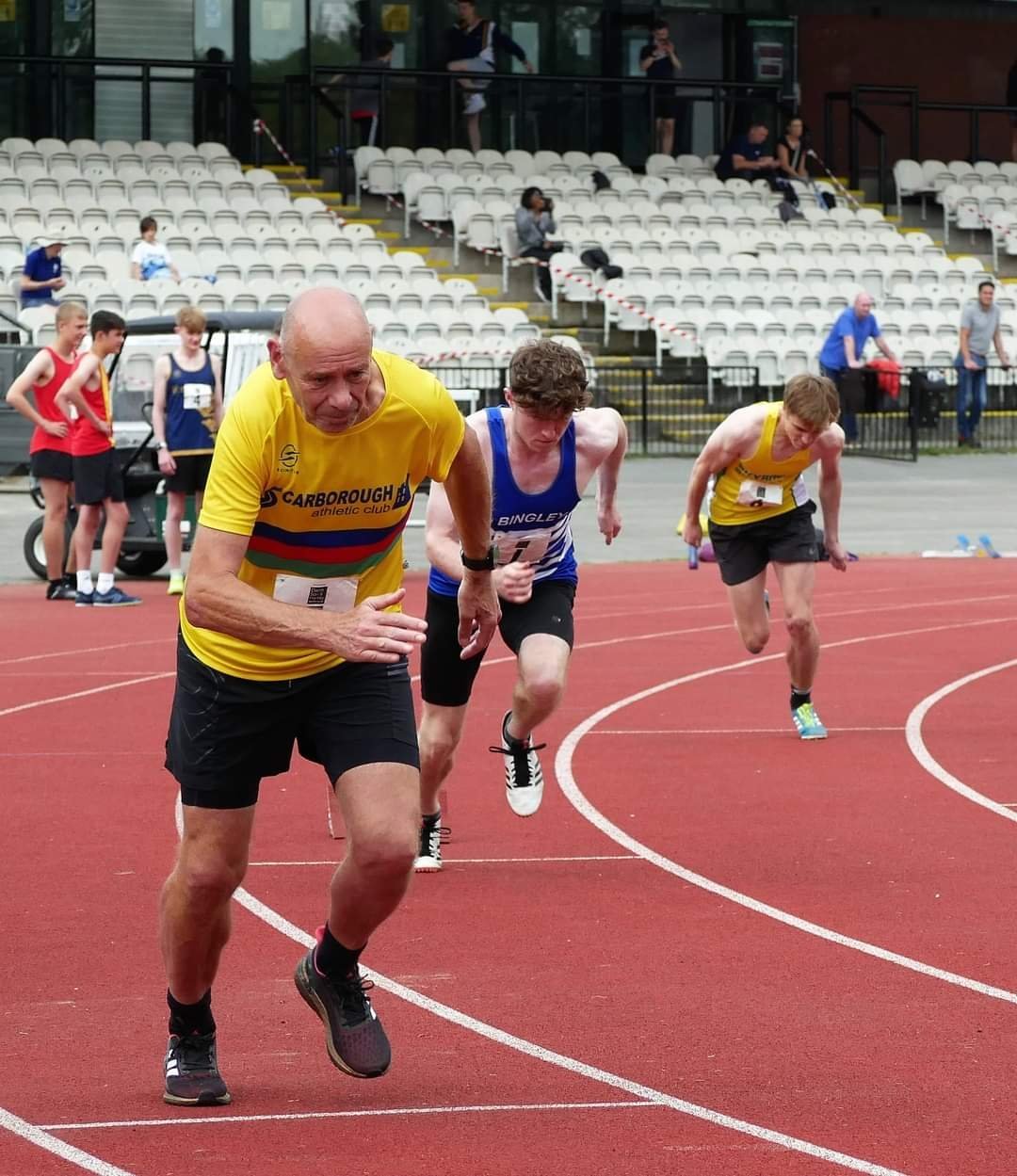
No time spent yesterday in the shipyard due to my track and field racing. I have included a picture taken yesterday of one of my races (400M). What is most noticeable is all the other runners appear to be around 17 to 18 years old and they were all very fast and very lean. I weighed in at a stately 63 years and was quite slow and not very lean🤣.

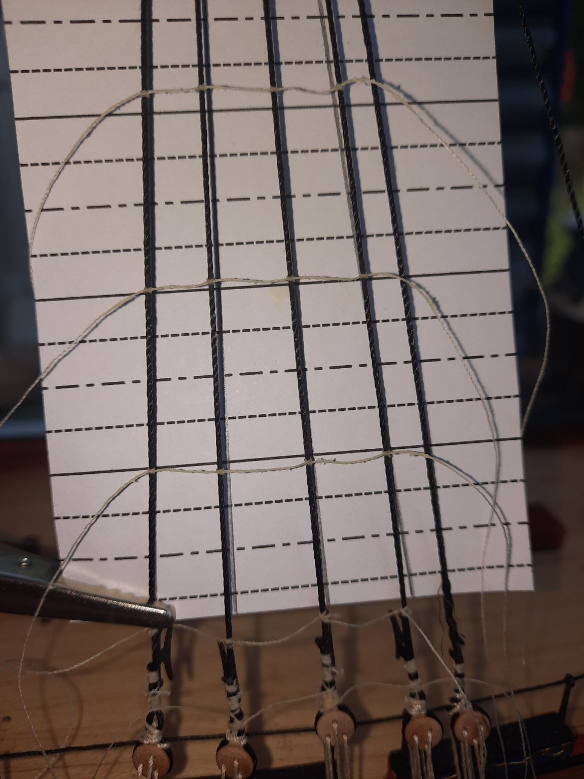
I have been busy today and I completed the port side ratlines. It took me aorund 4 minutes to add each ratline, a couple of hours of effort in total.
In this picture the template has been positioned and the first three ratlines added.
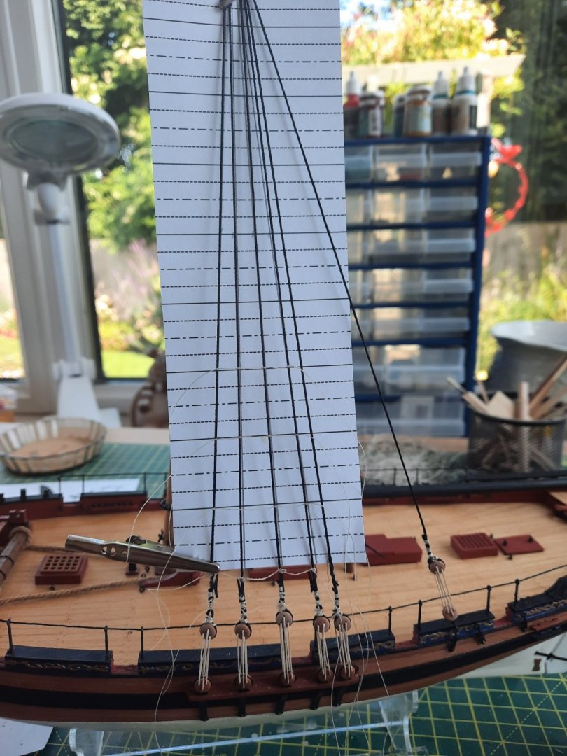
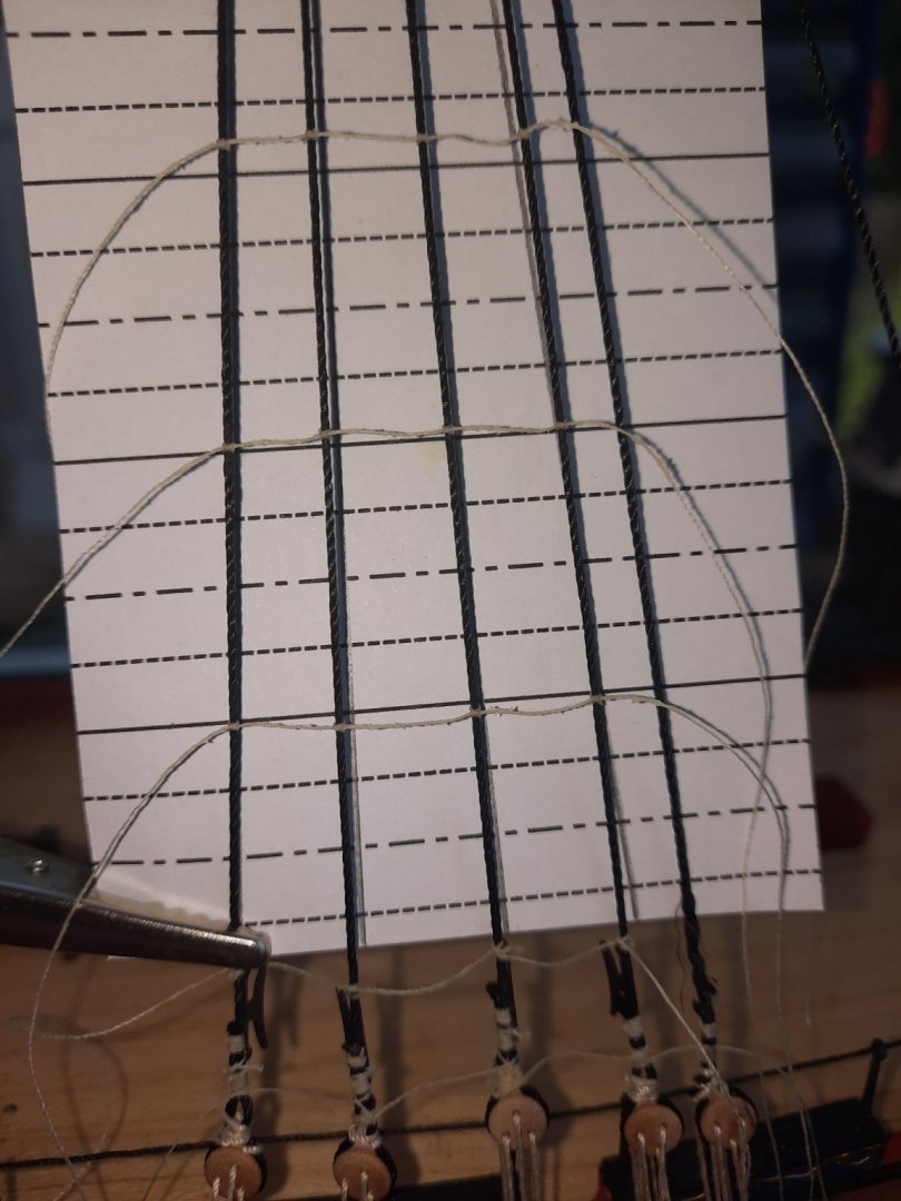
This is a close up of the first 3 ratlines. These ratlines are correctly positioned, they look wrong due to the parallax error.
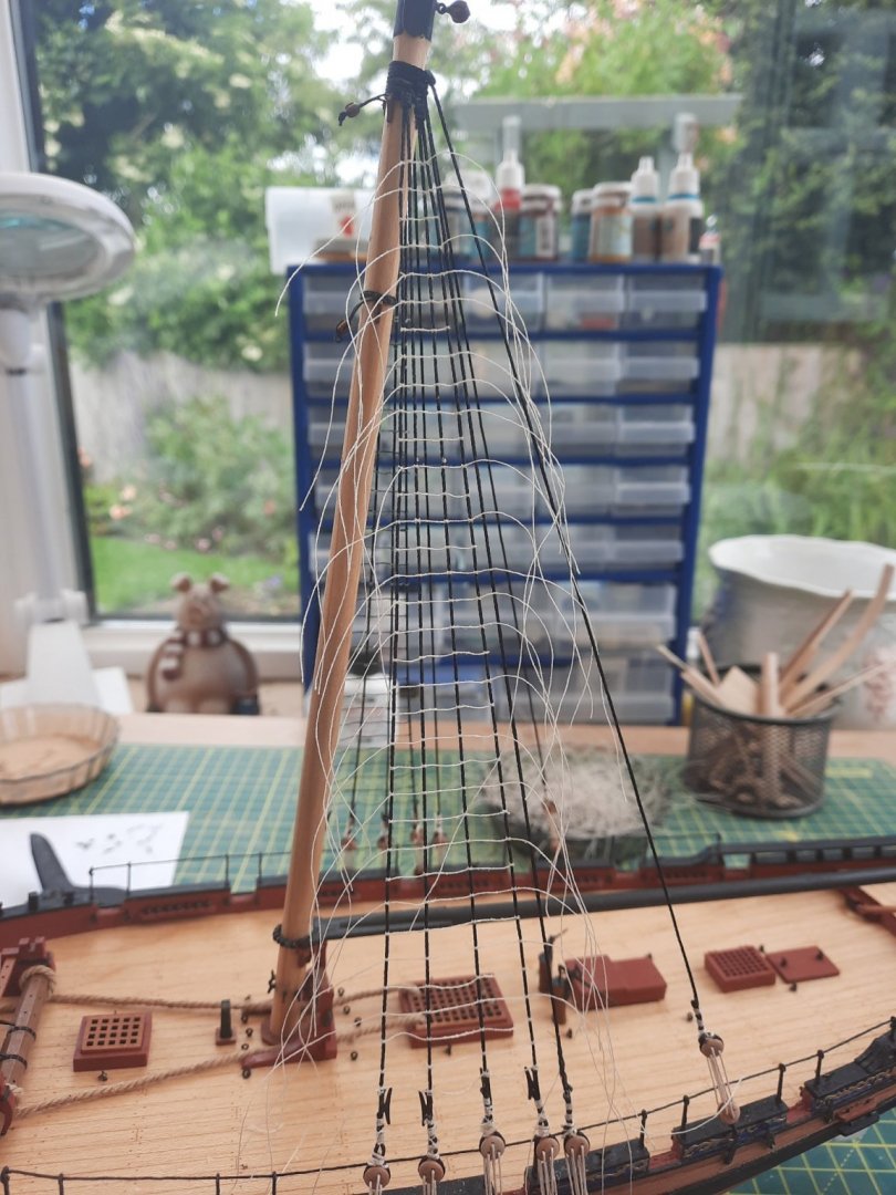
The ratlines are completed, some ends still require to be trimmed.
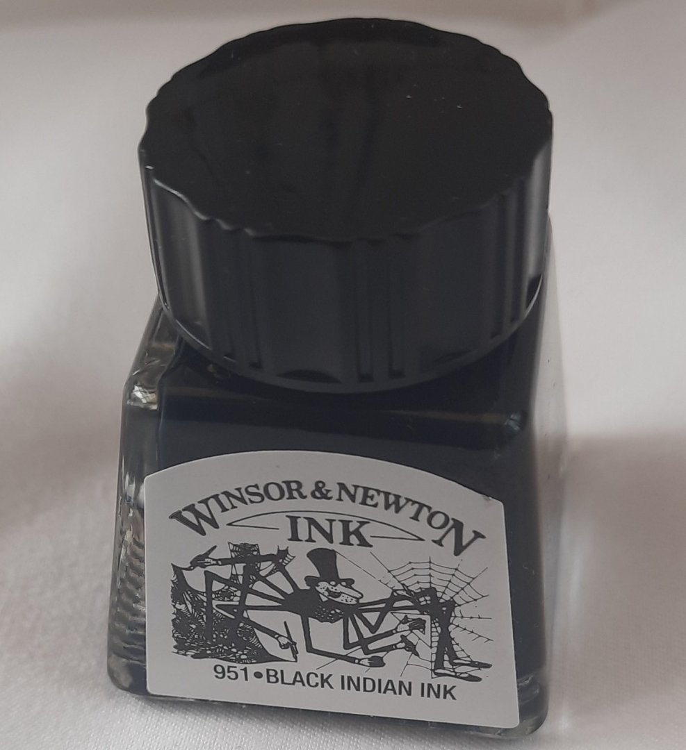
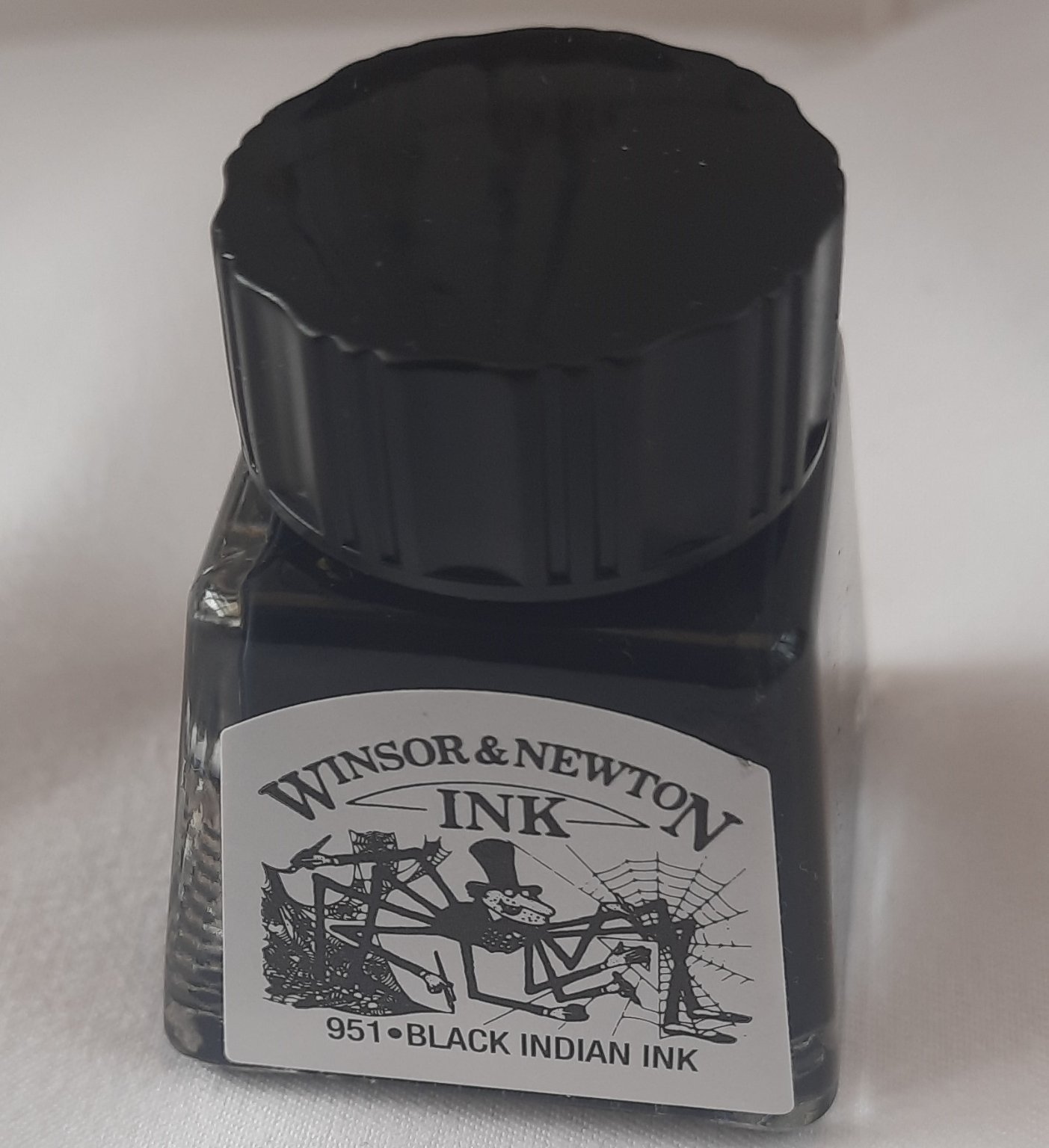
This is the indian ink I use to dye the ratlines
The ratlines have been trimmed and dyed black. As can be noted in the picture I have also started to add the missing back stays. Each of the two 5mm single blocks that are dangling from these stays will be rigged through some more blocks before being secured to their respective backstay iron plates

- Ryland Craze, Oboship, CiscoH and 1 other
-
4
-
8 minutes ago, Freezing Parrot said:
Very nice build! I appreciate your closeup shots of the details as you go along. Very helpful!
Hello Mike
I am not a great picture taker, but I am glad you are finding my log helpful.
-
I have finally completed the ratlines on the starboard side. I had to do it in fits and starts as my mother was being moved into nursing care so I had quite a bit to sort out in that regard. I have a track and field event tomorrow where I will be racing 400M, 800M 1500m and 5000M so will have little or no time to start on the port side ratlines. I am currently ranked no 1 in Yorkshire in my age group (60-65) and 14th in the UK. These rankings will drop dramatical as the lockdown eases and the proper track and field runners start competing again.
Pictures of the completed ratlines
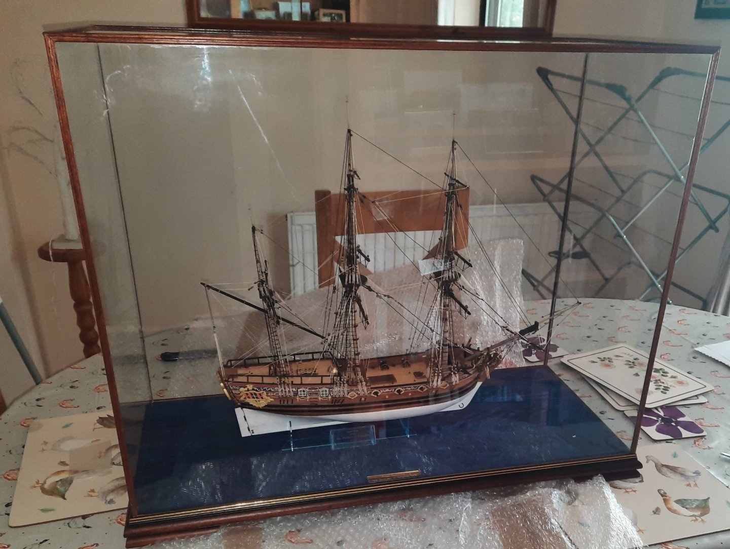
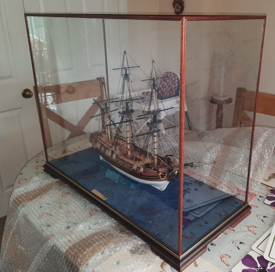
The display case I ordered for my Duchess Of Kingston build arrived yesterday. The Duchess does look nice in the case, however the case does not look right on the planned location which is a shame so putting the Duchess in a glass case has been side-lined for the time being and she is now uncased and back on top of the book case in our dining room.
- Rik Thistle, chris watton, DelF and 1 other
-
4
-
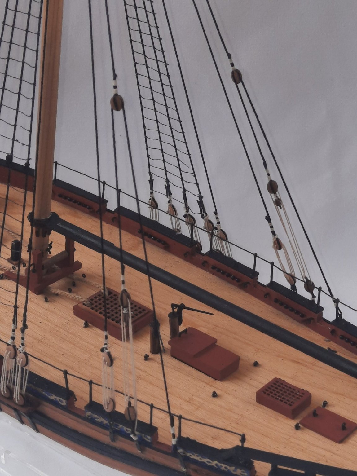
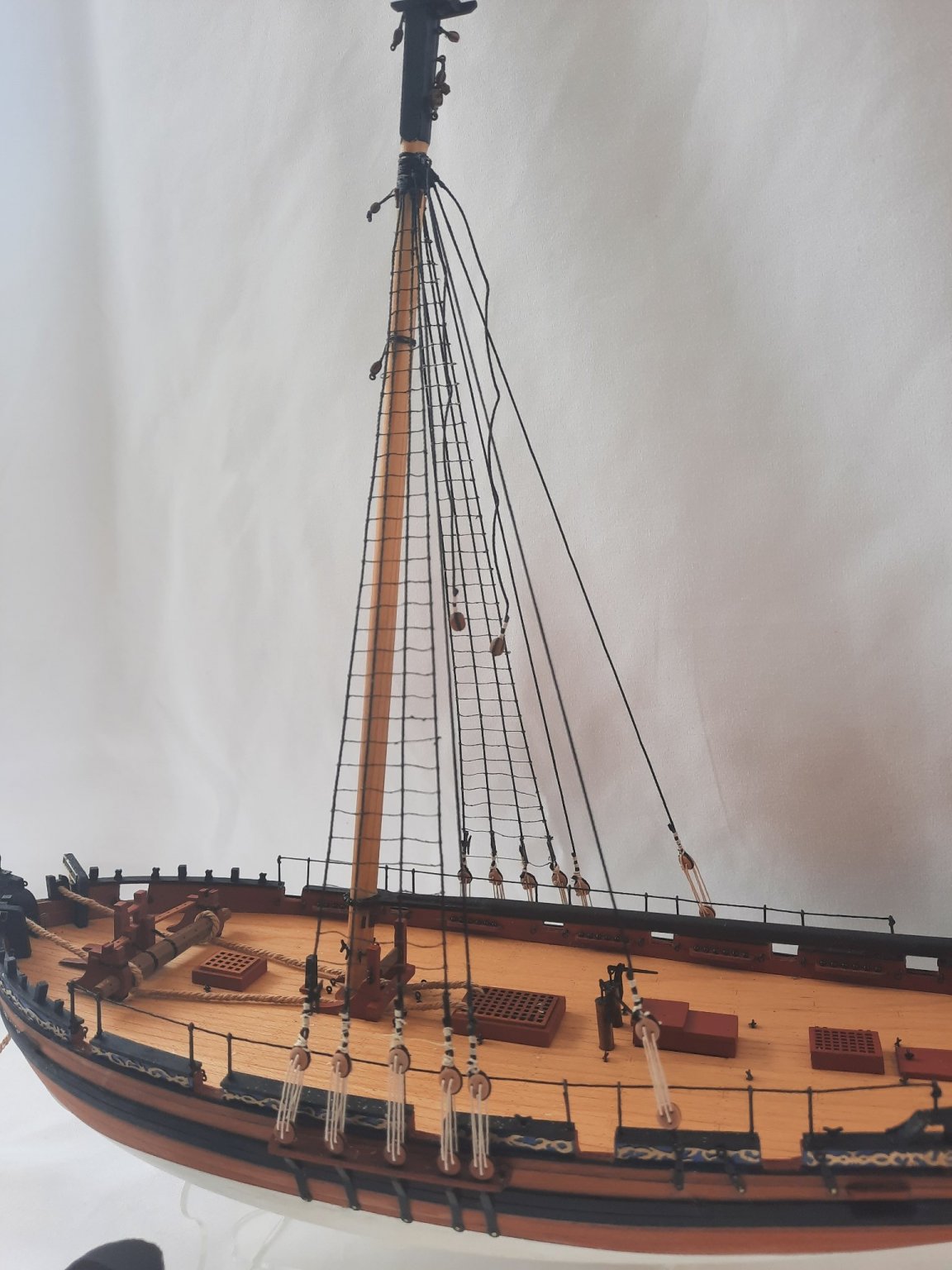
Moving forward I have now added the shroud lines to the channels. Before moving on to the ratlines I decided to add the Main Boom as well.
A couple of pictures of the completed shrouds and main boom

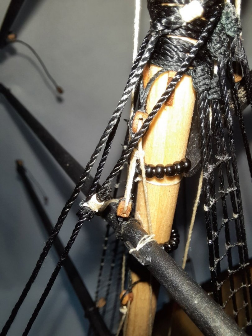
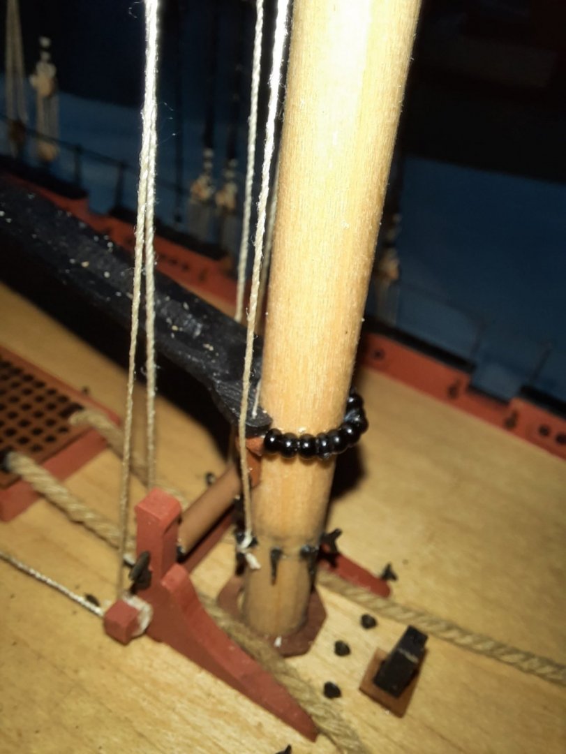
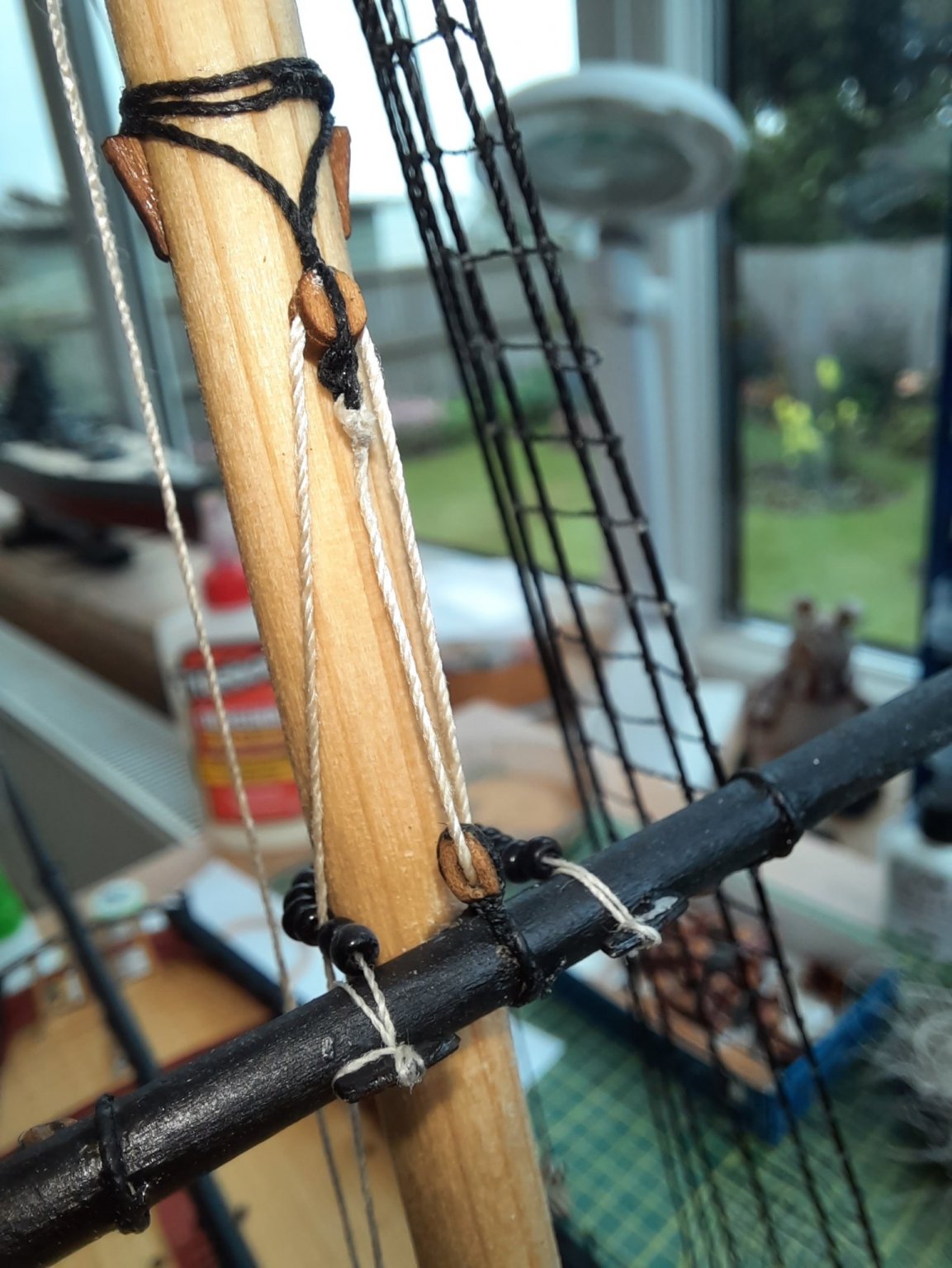
This is a close up of the parrel beads securing the main boom to the main mast.

With regard to the ratlines I decided I would add the bottom two ratline first as these need to be positioned around the seizing and shroud cleats. I used 0.1mm natural thread. I opted to use the Gutermann colour 722-1 thread rather than the kit supplied thread as this type of thread was supplied with the DOK kit and I really liked it.
The natural thread is dyed black. The completed ratlines are not brilliant but I can live with how they look.
As I have said before I actually like the task of adding the ratlines. The process I use is to fit every 5th ratline first, then I add the middle ratlines between each 5th before adding the remaining two ratlines. I can only work left to right as I seem to get a brain freeze when trying to tie a clove hitch knot when working right to left.
This is the start of the ratlines.
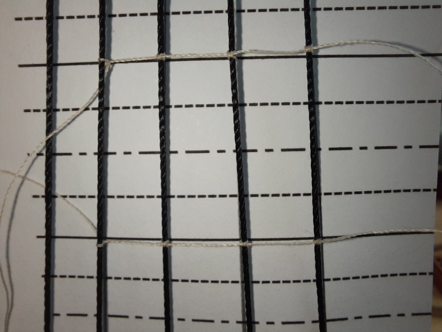
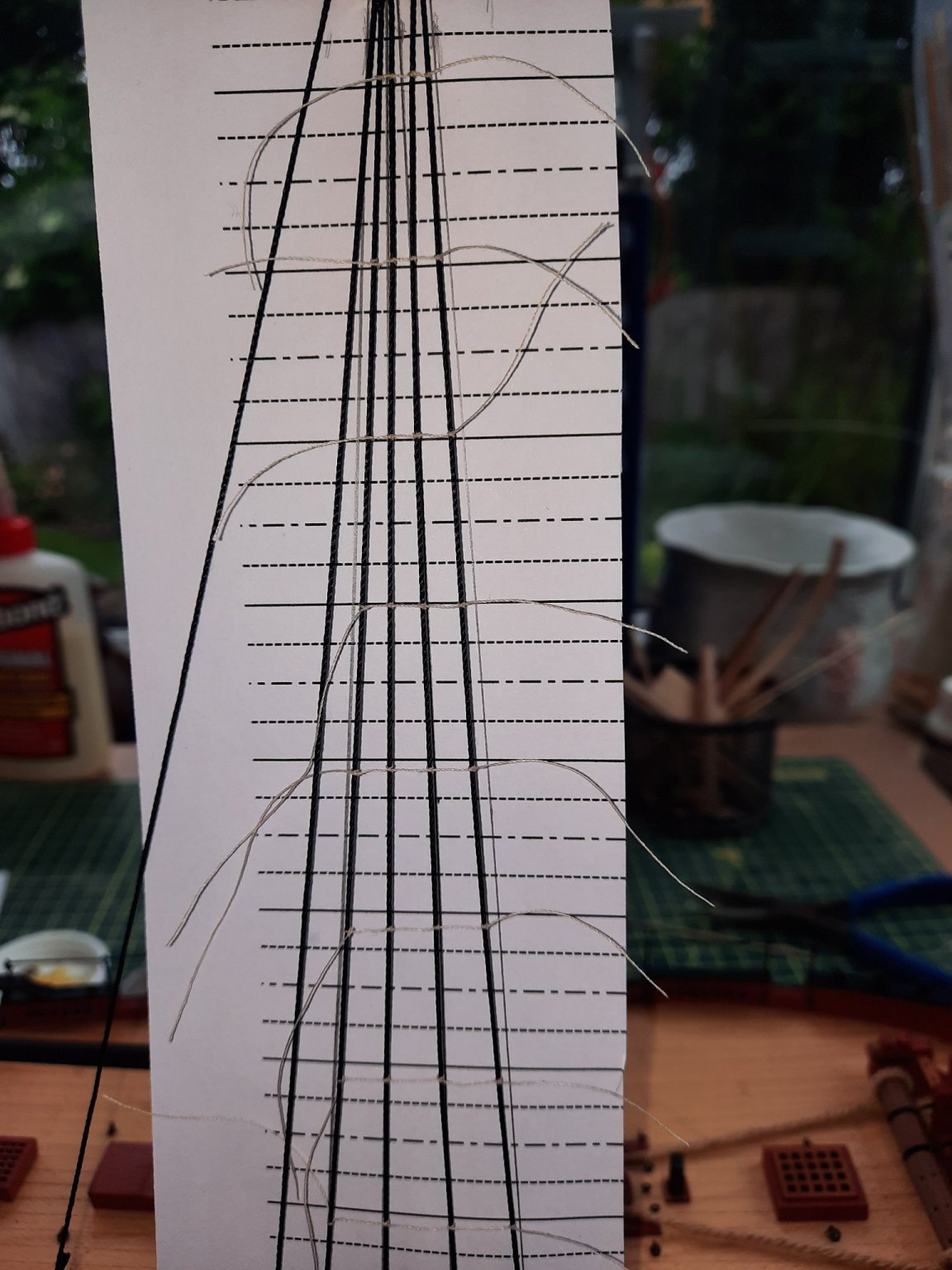
This picture shows the template in position. The solid lines represent every 5th ratline line position. The dot-dash lines represent the middle section between every 5th ratline and the dotted lines represent the final ratlines to be added.
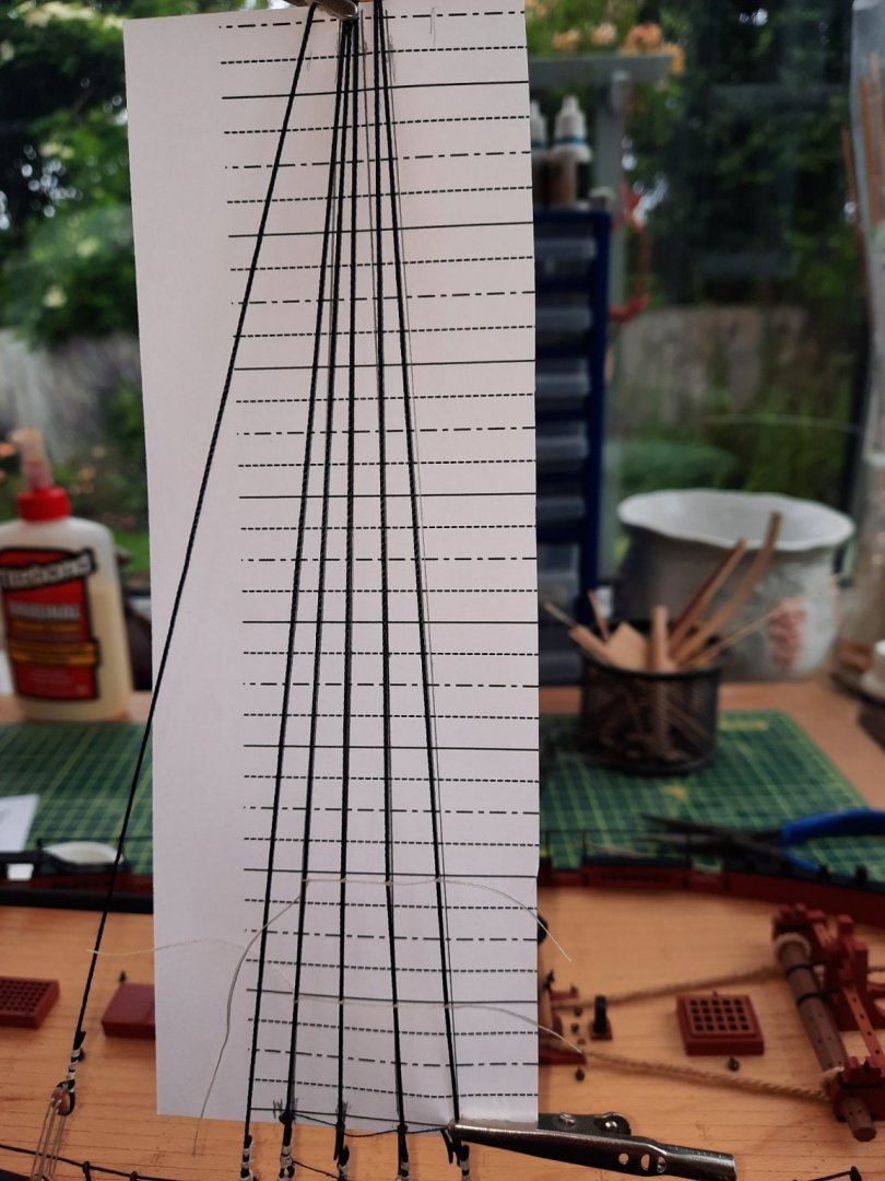
I have now added every 5th ratline. They are all correctly positioned even though the camera angle makes it look otherwise. These completed ratlines have had a diluted pva solution applied, wihich will help to stiffen the ratlines and will also (hopefully) prevent the knots working loose when the excess thread ends are trimmed. I will dye all the ratline black on completion.

- Oboship, VTHokiEE, chris watton and 1 other
-
4
-
Good start. I really enjoyed building the Duchess.
-
45 minutes ago, Jasseji said:
This is superb work @glennard2523 especially the rigging
Hello Jacek
Many thanks for your comment, I am not the best rigger but with each build I am improving.
Glenn
-
Just now, Tim Curtis said:
Great kit...beautifully made.
Hello Tim
Many thanks, you comment is much appreciated.
Glenn
-
After much pondering I decided to leave the badly rigged starboard side shroud deadeyes. I have now added the lanyards to the starboard side backstay deadeyes. The final task was to add the shroud cleats to the first four leading shroud lines which was a little bit fiddly. Thankfully it did not take too long to complete the task. I found it best to tie the upper part of the cleat to the shroud first before tying the low part of the cleat to the shroud.
I am now currently working on the port side shrouds and expect to complete in the next day or two. My time has been limited recently due to my mother being taken in to hospital.
Once the port side shrouds has been completed I can move to to adding the ratlines. I discovered, when working on the Duchess of Kingston, I quite like the routine of adding the ratlines.
- Oboship, DelF, Tim Curtis and 2 others
-
5
-
I have started to add the deadeyes and lanyards to the main mast shroud lines. I have never been very good at adding deadeyes to shrouds and then applying the correct tension to the lanyards. I am slowly improving but my technique still needs a lot more work to get nice looking results as will be evident when you look at the photos below. I have a lot of things to ponder before moving on, as I will detail later on in this post.
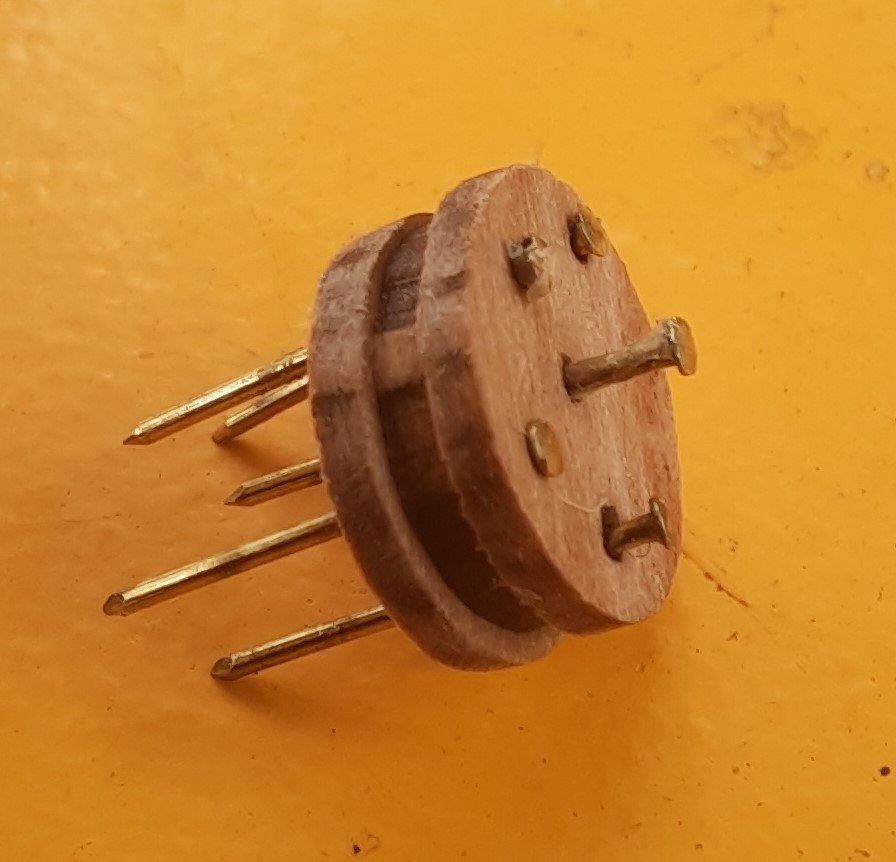
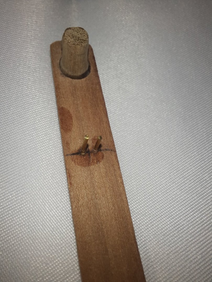
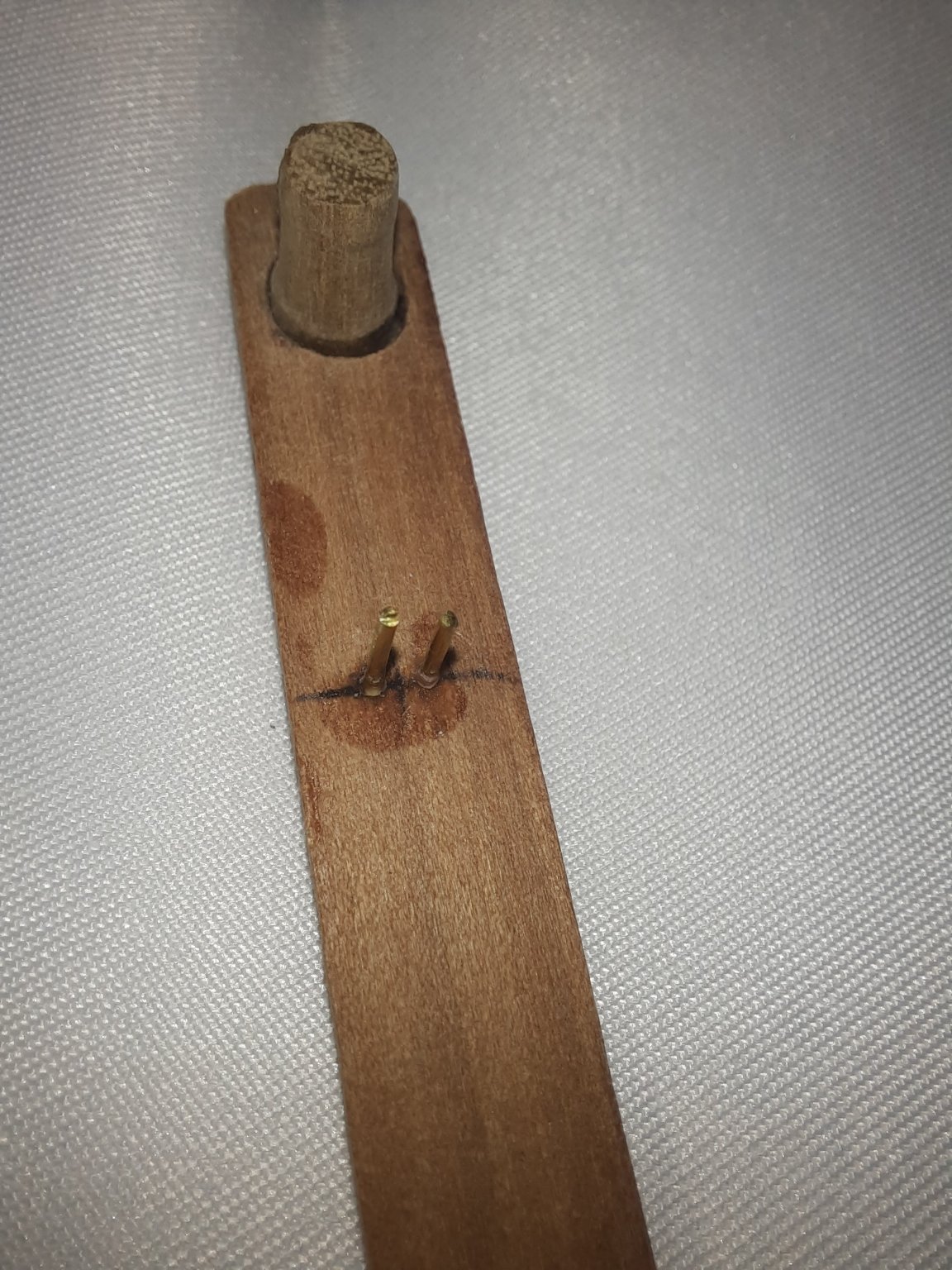
When rigging the Duchess of Kingston I made a jig to help set the position of the deadeye. It is simply a piece of 5mm dowel which is used to represent the shroud deadeye position and two pins which locates the jig to channel deadeye. I have attached a photo of my jig.
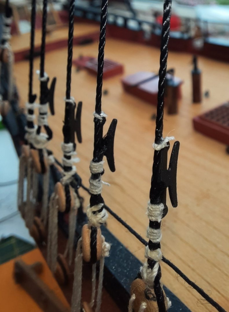
The next photo shows the jig in position with the first channel deadeye
The shroud is then wrapped around the dowel, and the seizing is applied using a 20mm length of 0.1mm natural thread. Once the seizing is completed the loose shroud end is pulled which then tightens the loop around the dowel.
A touch a ca gel is then applied to the seizing and the seizing thread ends trimmed. Next the deadeye is added to the loop, ensuring the holes are correctly positioned. Next I cut a 25cm length of 0.25mm natural thread for the lanyard which threaded through the deadeyes as shown in the photo below
The process was the repeated for the next shroud line
Now come the dilemma. As can been in the photo below seen the two right sided deadeyes and possibly the one on the far left are just about acceptable. The other two are not very good with regards to the position and / or seizing.
a) Do I accept the bad workmanship knowing it will probably look Ok when fully rigged and when displayed this side will not be on show.
b) Do I remove (some or all of) the shrouds and start again. This would be the right thing to do if I was building a model for display / commission.
If I do decide to redo, do just replace the two very bad shrouds or do I start again and redo all of them which will given a chance to try to improve my technique. I am currently undecided. I decided to build the Cutter Alert to continue my support of @chris watton with his Vanguard Models venture and to fill a building void after completing the Duchess Of Kingston until the release of The Sphinx which will be my next major build project. I am enjoying the build and ideally I would like to build the kit to help showcase Chris excellent design work and kit quality. On the other hand I want to get the model built before The Sphinx becomes available and to have a couple of weeks break. I think I will need another 6 weeks to complete the rigging which seems ideal with the forecast Sphinx release date.
Also I am not sure what I will do with the Cutter Alert, once it is complete. It will probably stay in the conservatory (which is my shipyard) so this side can be hidden from view. I think I should have enough spare 0.75mm black thread left should I decide to rework the shrouds.
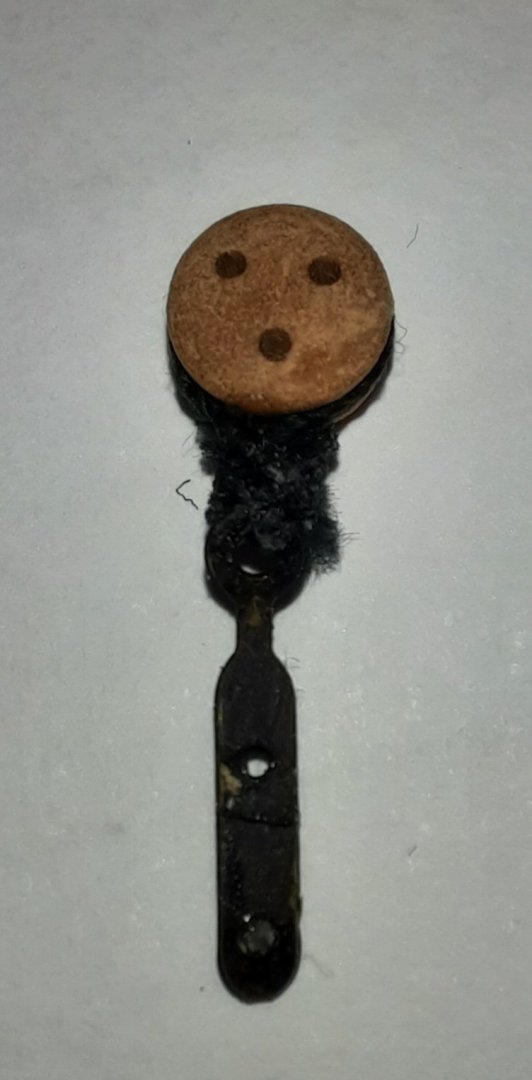
I have added the backstay deadeye to the small chain plate and is now ready to be rigged.
- chris watton, Oboship and DelF
-
3
-
6 hours ago, glbarlow said:
So 39 for everyone else😊
Make that 38 with 2 required for the two Glenn's. 😀
- KentM, chris watton, glbarlow and 2 others
-
5
-
3 minutes ago, chris watton said:
Initial production run will be for 40 kits.
I will be buying one of these kits when the order goes live.
- chris watton, KentM and Rustyj
-
3
-
@James H it looks amazing, excellent building skills and I'm sure the manual will be epic.
- mtaylor, KentM and Keith Black
-
3
-
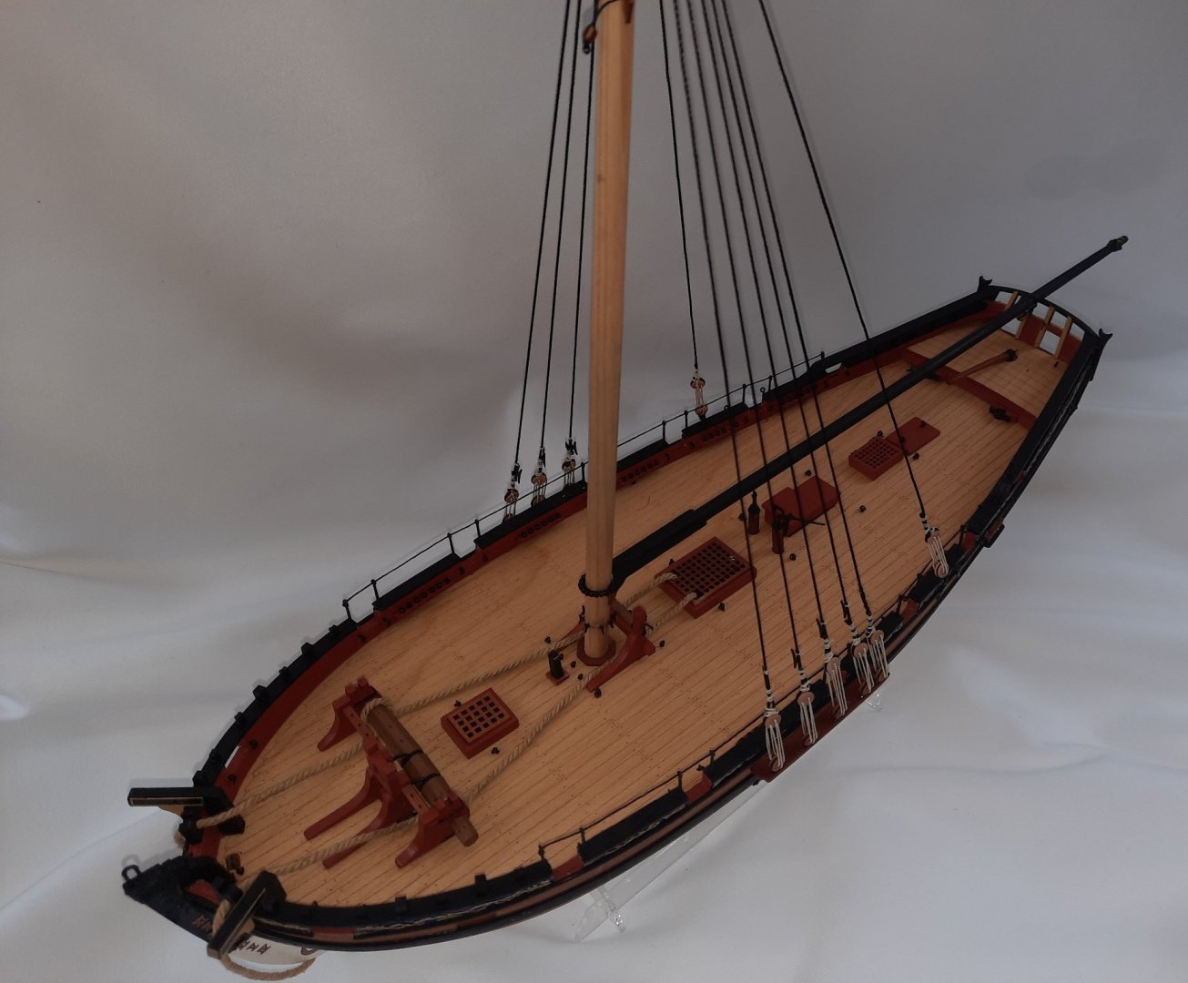
A little bit more progress.
I started by applying a couple of coats of Tung Oil to the wooden areas. I really like the finish.
Next I added the anchor cable. This is a length of 1.6mm diameter natural thread. I applied a touch of CA gel to one end and cut a taper. I was then able to thread the cable through the hawse hole, then around the deck items and finally back out through the other hawse hole. As can be seen in this photo I also replaced the main mast belay pin rack with cleats.

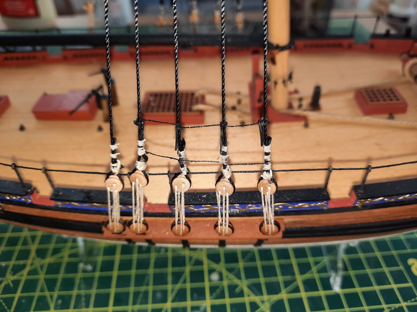
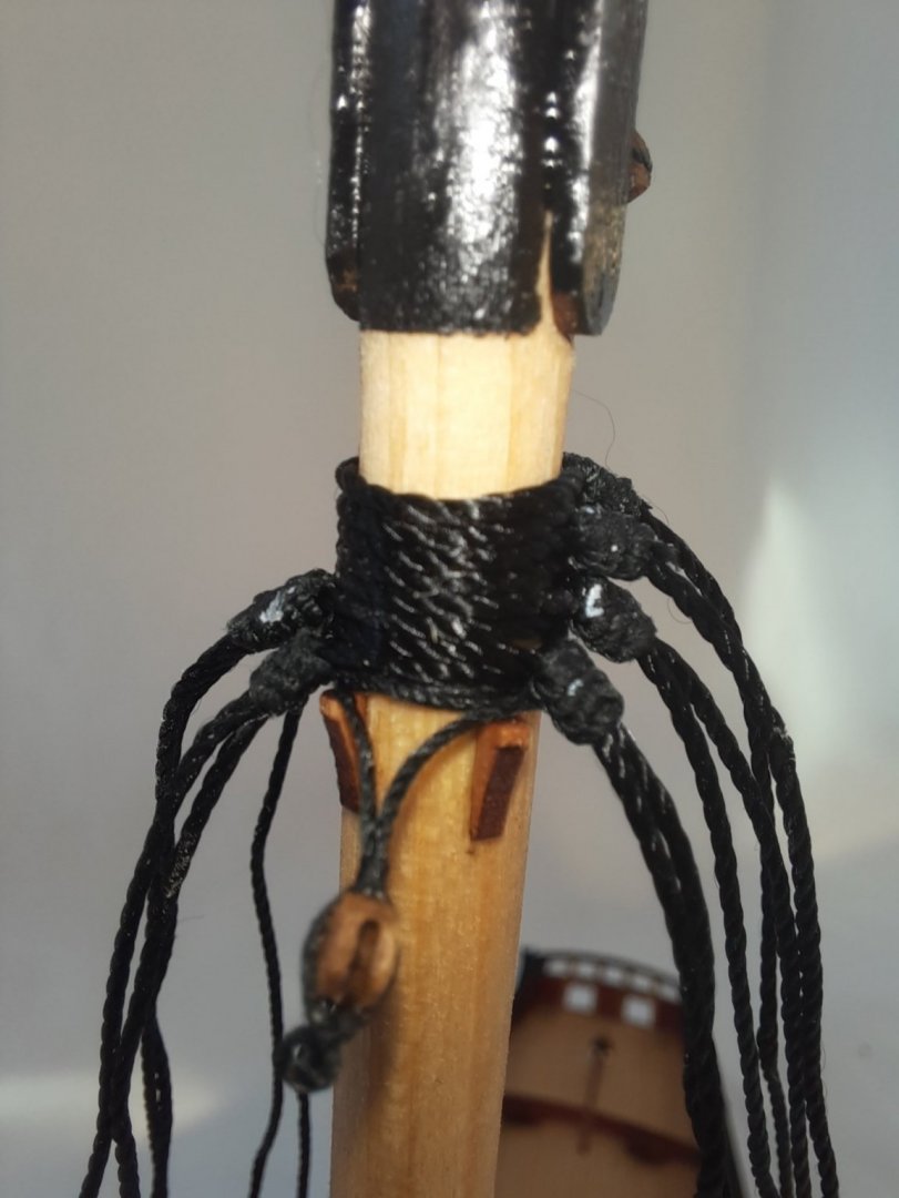
Next I moved on to rigging the Cutter Alert. Using my quad hands I started the process by adding the shroud lines to the main mast. I cut 4 x 60cm lengths of black thread for each of the "double" shrouds and 4 x 40cm lengths for each of the "single" shrouds.
I used alternate top and bottom half hitch knots with 0.25mm black thread to seize the shrouds. This is a picture of the first double shroud. The two ends of the seizing thread is ready to cut trimmed. I applied a touch of CA gel before I cut the excess thread. For added security I then added a diluted PVA wash over the seizing.

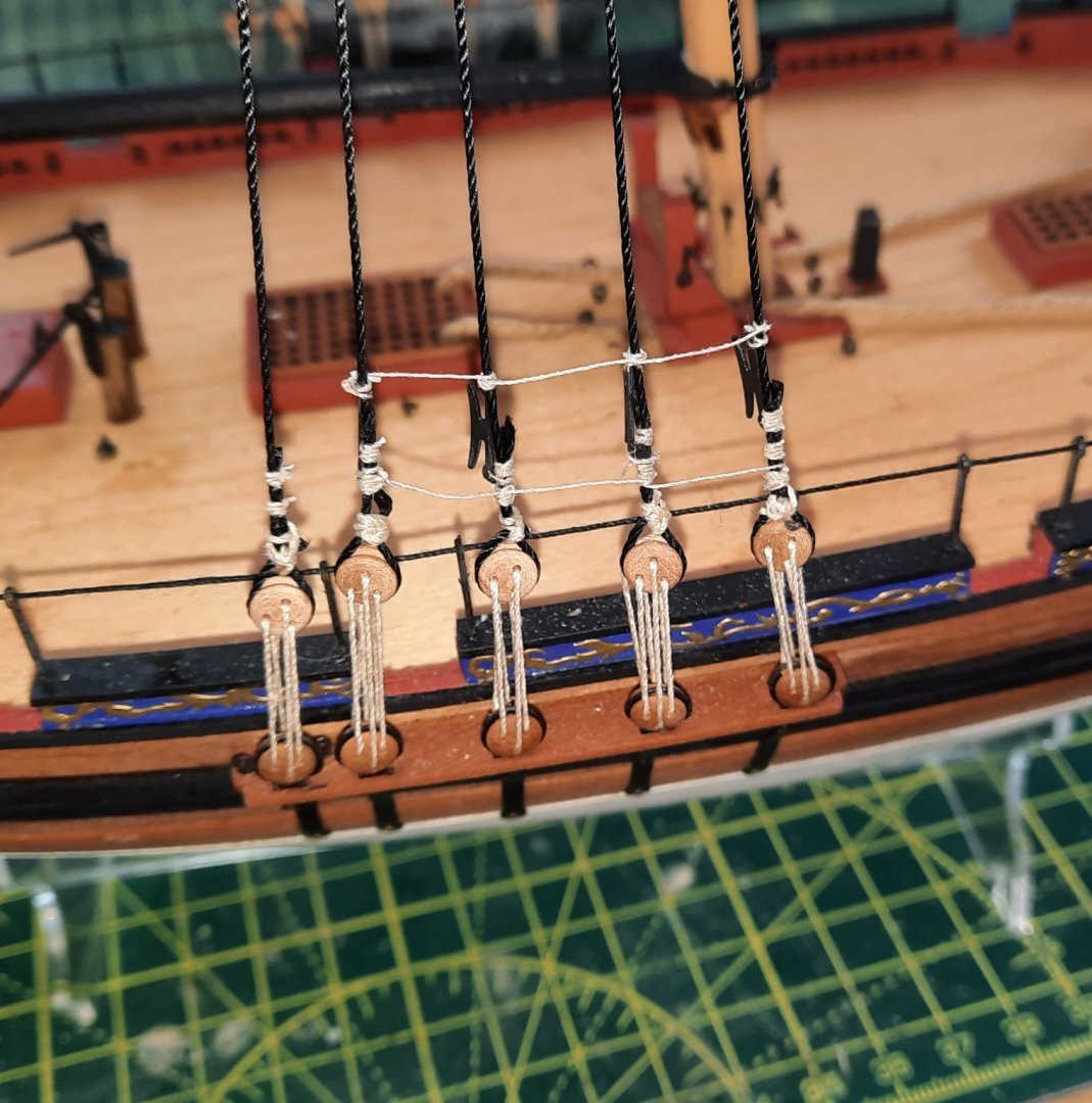
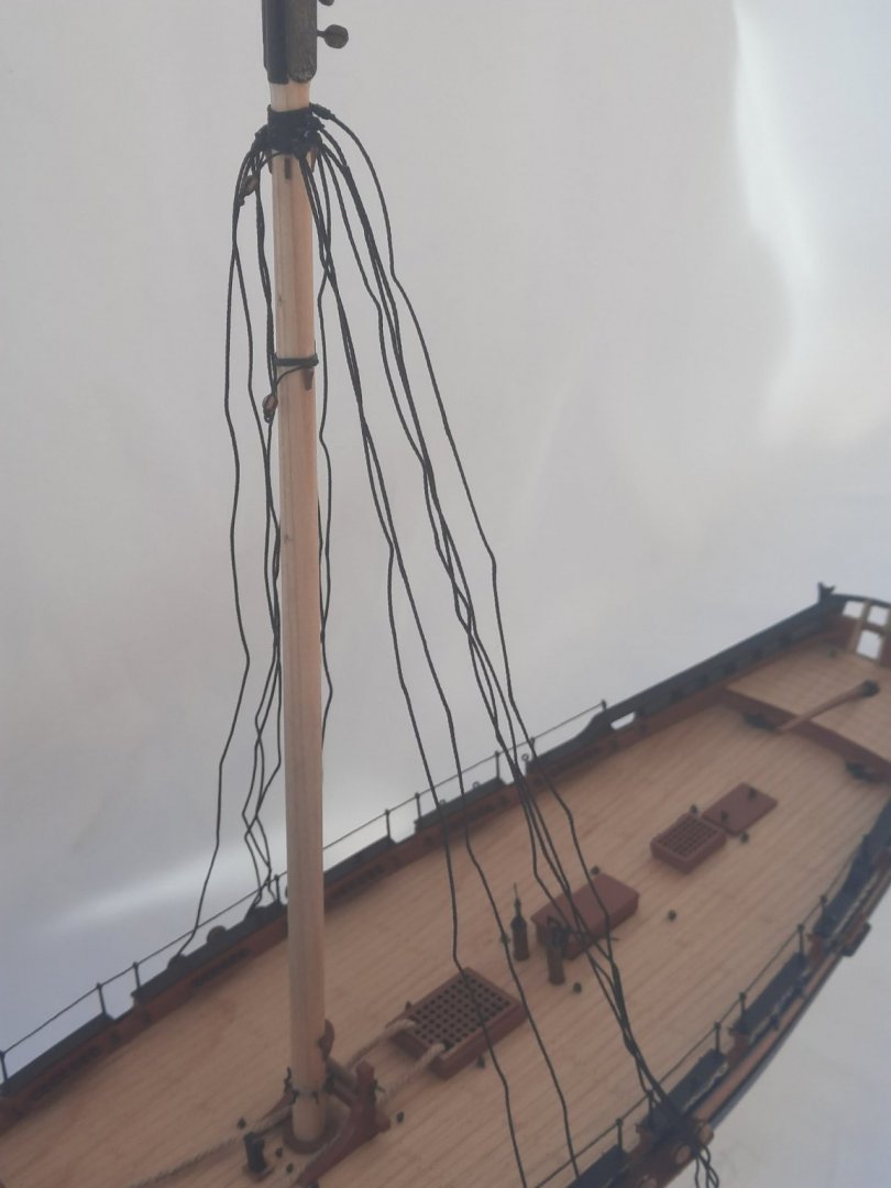
This picture was taken after all the shrouds had been added and looks reasonably neat and tidy.
Finally a standard picture showing the shrouds before the deadeyes have been added, which will be the next task.


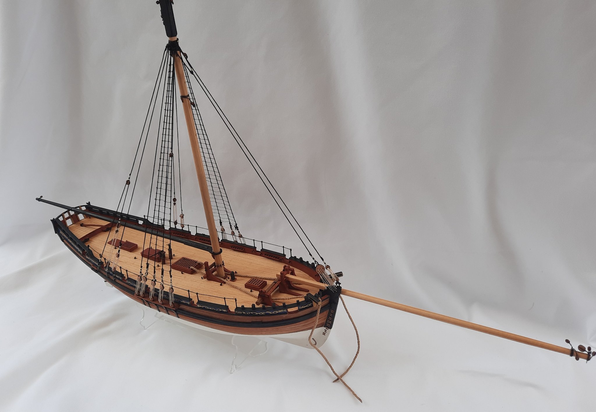


HM Cutter Alert by Glenn-UK - FINISHED - Vanguard Models - 1:64 scale - by Glenn Shelton
in - Kit build logs for subjects built from 1751 - 1800
Posted · Edited by glennard2523
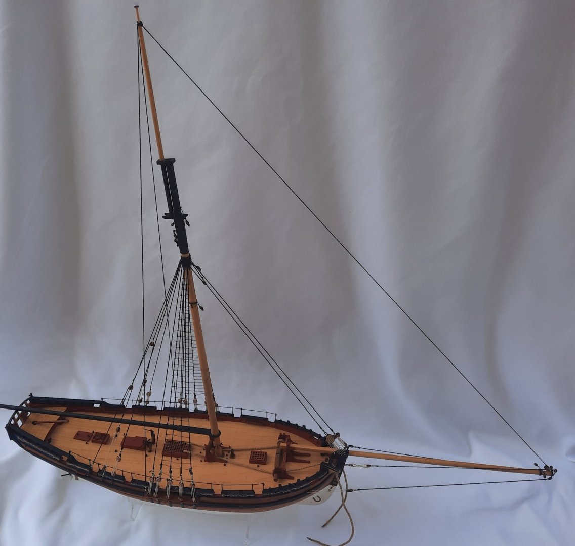
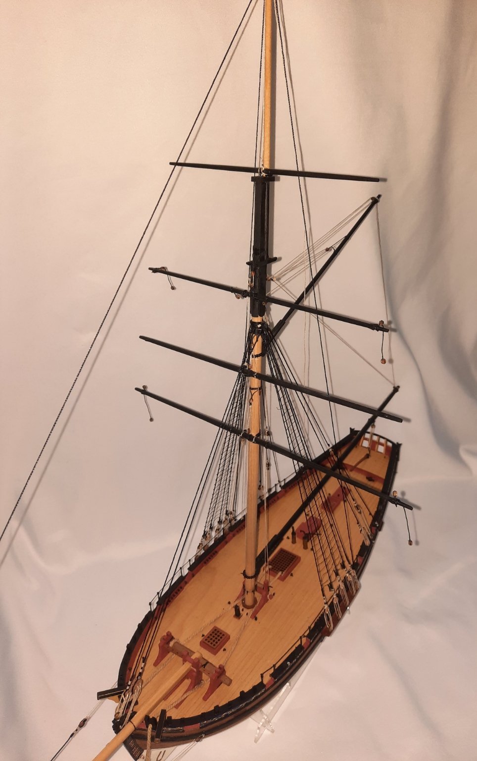
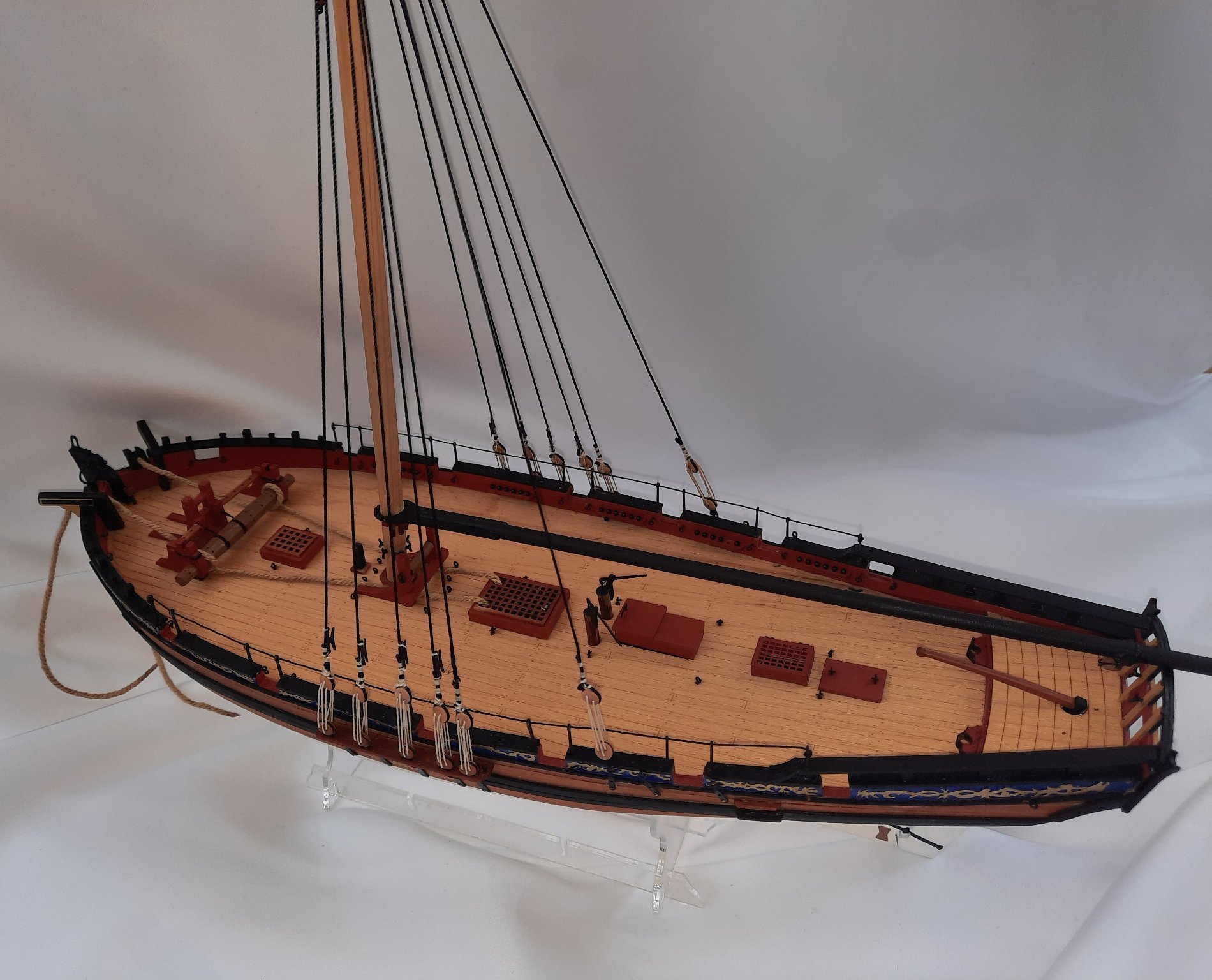
Very quick update. The rigging is now complete. I have also added the rigging for the Jib Sail but I just need to add the toggle to complete.
All that is left to do is to add the swivel guns and cannons and then to secure the two anchors.
I will do a more detail post with some better photos once the model is complete, but here is a quick photo.