Beef Wellington
-
Posts
2,249 -
Joined
-
Last visited
Content Type
Profiles
Forums
Gallery
Events
Everything posted by Beef Wellington
-
 Very nice Christian, your ratlines are so neat!
 -
Just amazing what you are doing Greg. The detail on these is incredible, not sure how you keep your sanity!
-
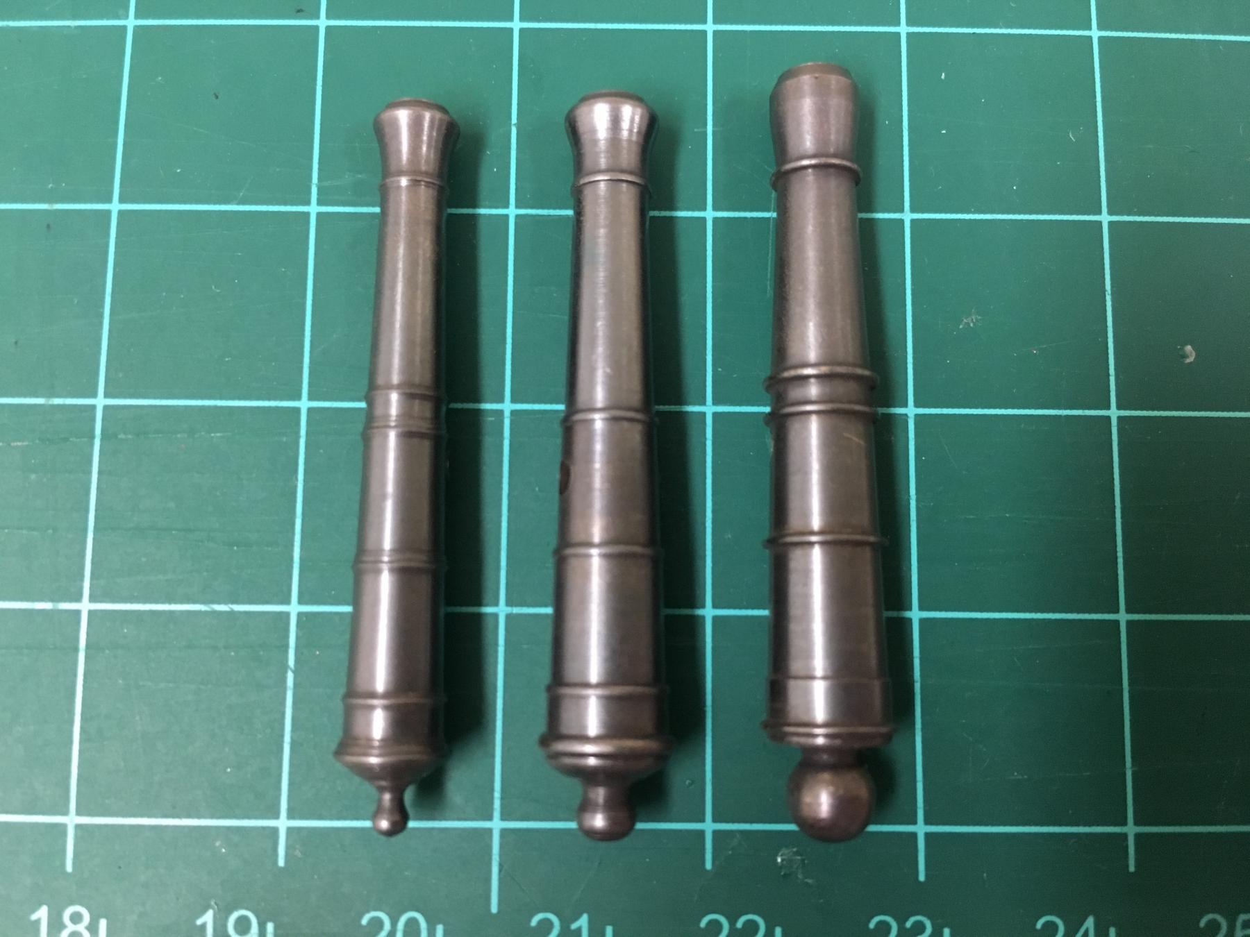
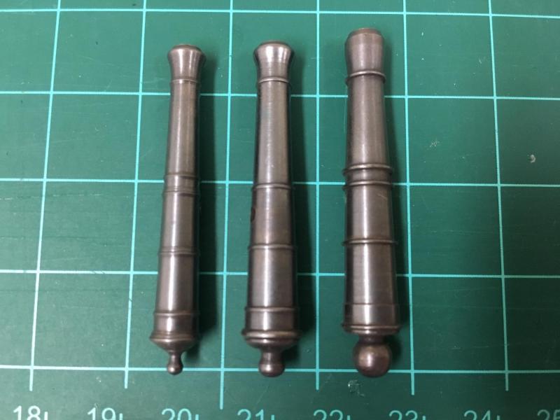
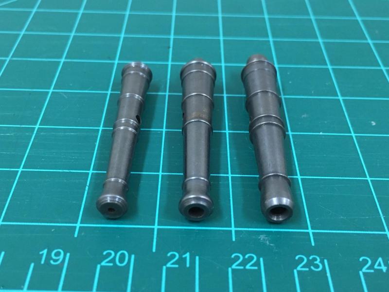
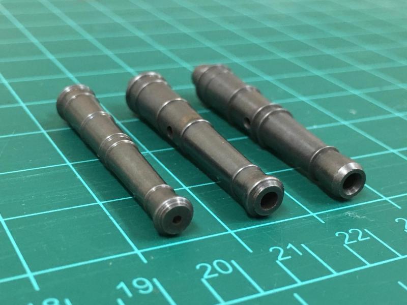
Hi Andy, think our minds think alike... I'd also suggest considering the barrels from RB Models. Hope you don't mind me posting pics, but you can see the side by side (from left to right) of Chucks, RB Models 44mm, and the supplied Caldercraft. Chucks are beautifully made, but I didn't feel that the scale was right for an 18lb'er, the bore being too small and overall it looks a little light. Feel both the bore and the cascable on the CC barrel are way too big and the shape of the muzzle just not right. I'm leaning toward the RB Models barrel.
-
You will need a gap, much smaller toward the center of the yard, but increases on the outer boom iron - simply because the yards are tapered, but the stuns'l booms should be horizontal.
- 1,144 replies
-
- 1
-

-
- snake
- caldercraft
- (and 1 more)
-
The stuns'l booms don't have any rigging so nothing to worry about there,they are really just decorative in this simplified representation.
-
Jack, glad I found your build. This looks like a lovely kit so very interested in how she comes together, you're off to a solid start. All the CC kits seem to have their foibles despite being of generally good quality, sure you'll overcome the challenges.
-
a) I used what was recommended, no issues Yes, photos in my log think show this c) I used the caps, but as Davyboy pointed out, they are too big. I made card to simulate the various iron band, the PE end cap is not really needed and its easier to not use it I think.
- 1,144 replies
-
- 1
-
-
- snake
- caldercraft
- (and 1 more)
-
Can't remember what they are called (trucks?) - they are lashed to some of the backstays and they keep certain lines of the running rigging configured so they don't foul others. Not the best explanation, but hope it helps. They are called out on the plans if I remember correctly.
- 1,144 replies
-
- 1
-
-
- snake
- caldercraft
- (and 1 more)
-
The closeups on your rigging Bob are just amazing, beautiful work indeed. So crisp and clean. Well done.
-
Always the key references...D'Arcy Lever's "Young Sea Officers Sheet Anchor", and Lennarth Petersson's "Rigging Period Ship Models".
- 1,144 replies
-
- 3
-
-
- snake
- caldercraft
- (and 1 more)
-
Very nice Mark, its fascinating the different techniques used between Anglo and French builders, things one would assume would be somewhat consistent but guess both methods on the coamings worked fine. She's really looking great now (not that she didn't before... sure you know what I mean...)
-
Looking good Stergios, I mounted the bowsprit standing rigging before any of the masts and associated rigging without any problems,did not seem to get in the way at all (except for boomkins which went on with the masts)
- 1,144 replies
-
- 2
-
-
- snake
- caldercraft
- (and 1 more)
-
Hi Joe, The carronade port sizes on the plans are 14mm high by 13mm wide. Measuring my model, they're closer to 14mm wide and a touch higher. If you go with carronades I'd suggest figuring out where you will source them (I upgraded to the CC brass ones). If you decide to use those, then its definitely worth building one up to determine the needed height. If I had done this, I would have increased the height a little more as its a notorious problem that the 32lb'er can be tough to get correct alignment and not interfere with the top of the port. It'll also allow you to determine where the lower port sill should be. Hope that helps.
- 136 replies
-
- 2
-
-
- caldercraft
- Cruiser
- (and 2 more)
-
Looking great Joe. I know I mention this already, but if you do plan to use carronades then you probably want to increase the port size soon to avoid messing up your nice paintwork. The copper colour is gorgeous.
- 136 replies
-
- 2
-
-
- caldercraft
- Cruiser
- (and 2 more)
-
Cruizer-class Brig-Sloops of the Royal Navy
Beef Wellington replied to molasses's topic in Nautical/Naval History
Frolick, this does feel a little like conjecture. I know I'm going to sound argumentative, but think its important that opinions don't get confused with facts. There is a bigger picture here to understand here and its important to understand the broader strategic direction as well as just ship construction techniques. I'm not a professional historian, just a interested amateur whos done lots of reading from various sources. And yes, I have a sweet spot for the Cruizers.... Many significant, successful ships of wide array of rates, before and after, were built in private yards. Its not appropriate to conclude that private yards equated to lower quality/lower skill levels Timber availability was a concern, and had been before and was to continue to be after this period. Your interpretation reads a little like the 'tired empire on its last legs and the cruiser design was the best it could do' story, which clearly was not the case when you look at the size of the fleet and individual ships of the post war battlefleet right until end of sail. Ship design and the compromise with available funds had been a factor in the RN for centuries. There is a need to recognize how ships were designed and approved. It was very often Royal Naval policy to adopt, rescale and shamelessly copy successful designs. It is apparent from looking at draughts and models that the Cruizers owe a lot to cutter design, including the square tuck and significant rake of the keel. These ships were selected after building prototypes and letting the "best ship win", I don't think its an appropriate conclusion to reach that square tucks, despite being anachronistic, were necessarily compromises. The need for economy was driven more from manpower usage and the need to project naval power on far flung strategic stations with the dwindling number of sailors needed given the escalating threat. Therefor the cruisers provided an excellent balance of firepower, long range cruising ability and crew minimization (which is apparent when comparing the Swan to Cruiser classes, different ships for different roles). Now living in the States, it never ceases to amaze me that there is little understanding of the context of the US revolutionary war against the broader, and larger global war Britain was engaged in against Napoleonic France and Spain. -
Cruizer-class Brig-Sloops of the Royal Navy
Beef Wellington replied to molasses's topic in Nautical/Naval History
I think it shows the square tuck pretty clearly...I'll bet my lunch money. -
Cruizer-class Brig-Sloops of the Royal Navy
Beef Wellington replied to molasses's topic in Nautical/Naval History
I'm confused now. Are we agreed that the square stern was the norm for the Cruizer class, as evidenced by various contemporary models and plans, and that there were (possibly) exceptions to this for the small number of fit/teak built ships? If so, I'm happy -
Cruizer-class Brig-Sloops of the Royal Navy
Beef Wellington replied to molasses's topic in Nautical/Naval History
Hi Frolick, would you mind sharing some pictures of the plans you are looking at. Every plan I've seen of the Cruizer class on NMM has a square tuck stern, and that's certainly how the kits are made. Many thanks. -
Cruizer-class Brig-Sloops of the Royal Navy
Beef Wellington replied to molasses's topic in Nautical/Naval History
Can you confirm your comment Frolick, I think it was the opposite, only the fir/teak built DID NOT have square tuck stern. -
Hi Alan, I somehow missed your progress here, just amazing what you've accomplished from start to finish. I appreciate you sharing your learning curve and your beautiful ship with us. I wan to go back again and read from the start
-
Cruizer-class Brig-Sloops of the Royal Navy
Beef Wellington replied to molasses's topic in Nautical/Naval History
JimSmits put a snake figurehead on his 'Snake', captains desires are held in check only by the size of their purses :D -
Hi Lou - thats in my back pocket, but I would need to buy and get proficient with a CAD application. I do want to do this, but just trying to manage how steep and long my learning curve is :-) Hi Chris - sadly no table saw, but interested to learn what you used. Thanks all for sharing ideas and comments.
-
Hi Andy, I did look that, but the price is so extortionate that I dismissed it, I've been mulling over for quite some time the other options: making my own following the FFM guidance, but think this is too fiddly at 1:64 to get any better results Buying a home 'PE kit' - would probably require a software investment as well to get good results Laser-cutting in wood - would require investment in software and would likely be very (too) delicate at this scale Overall, think I've made my peace with the parts, once things are assembled and get a lick of paint it I can step back and decide if its OK. I've gone down so many circuitous routes already that I don't want to get into analysis paralysis. I can do that when I get to moldings
-
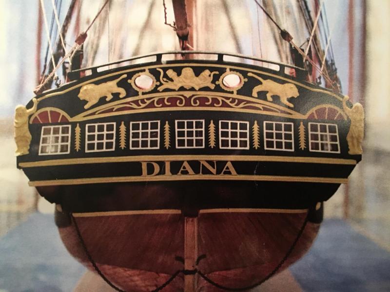
Nice to have you look in Lou, thanks. Carl: You are right the center window is slightly taller on that side, but think its manageable. The challenge is that there is no perfect solution because the PE pieces are just not 100% correct for any solution, its a case of finding the best compromise. I'm a little disappointed in this as the stern gives so much character to the ship, and the Swan/Pegasus kits have them perfect. Heres a picture from the instructions of the Caldercraft prototype, you can see the problem here as well. If you match the height at center, its then off with the 3rd light, and also the vertical alignment is worse... 'Nuff said "
-
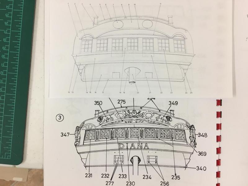
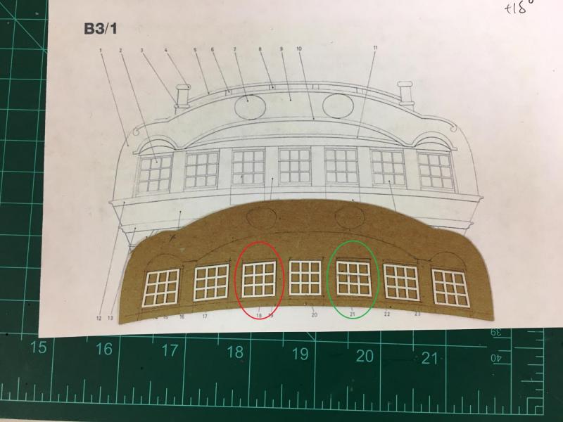
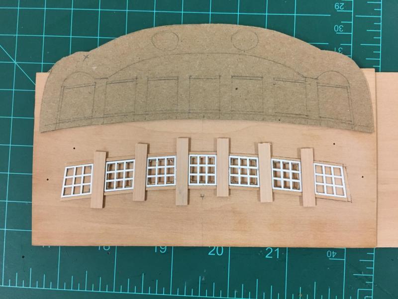
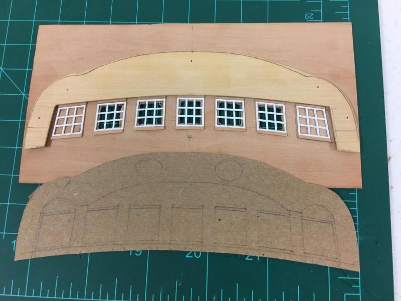
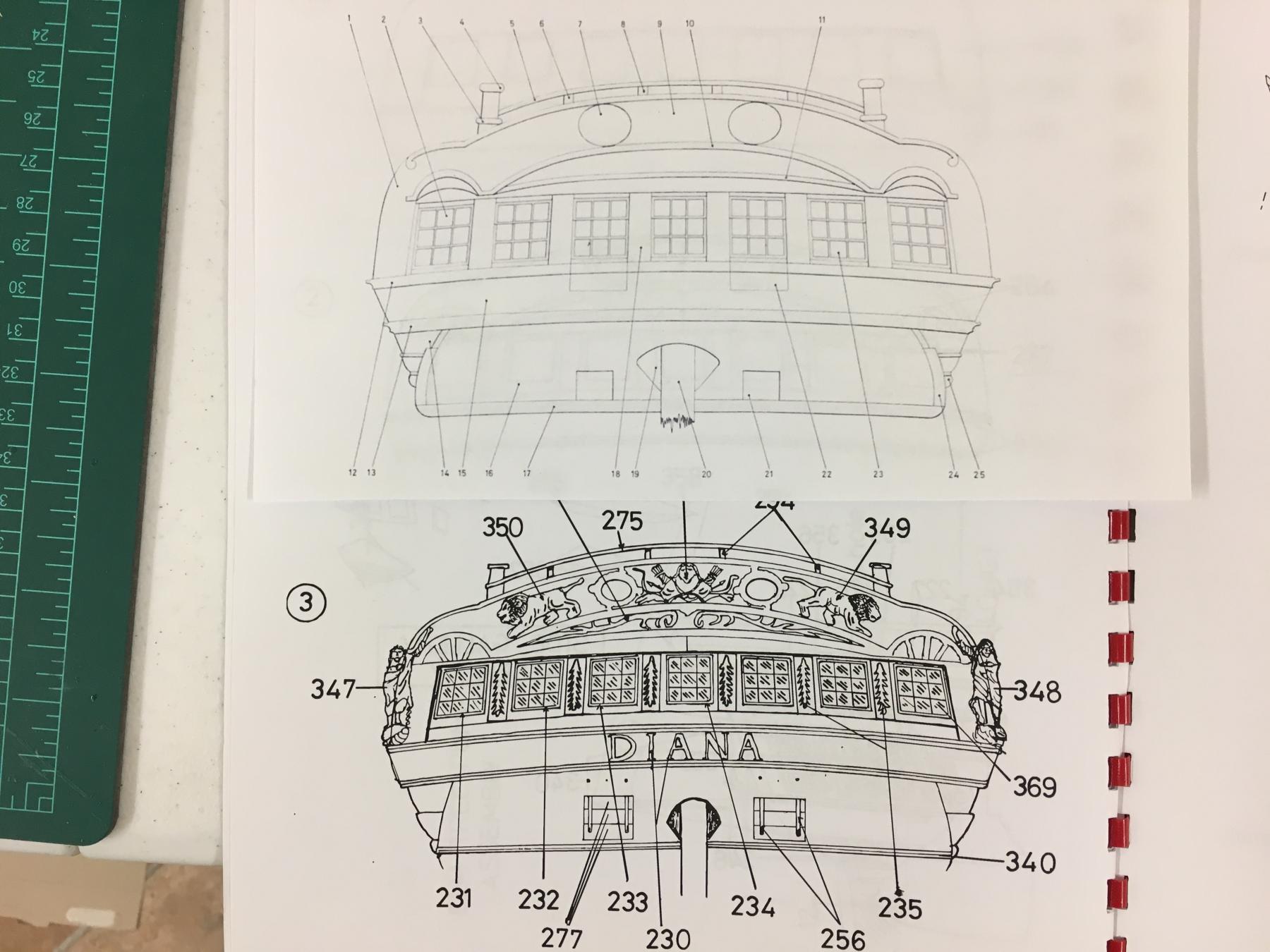
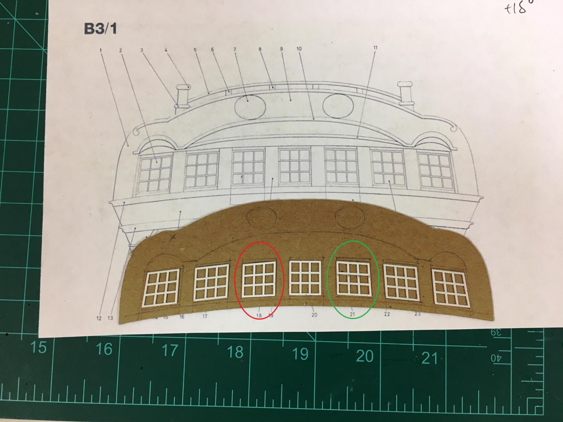
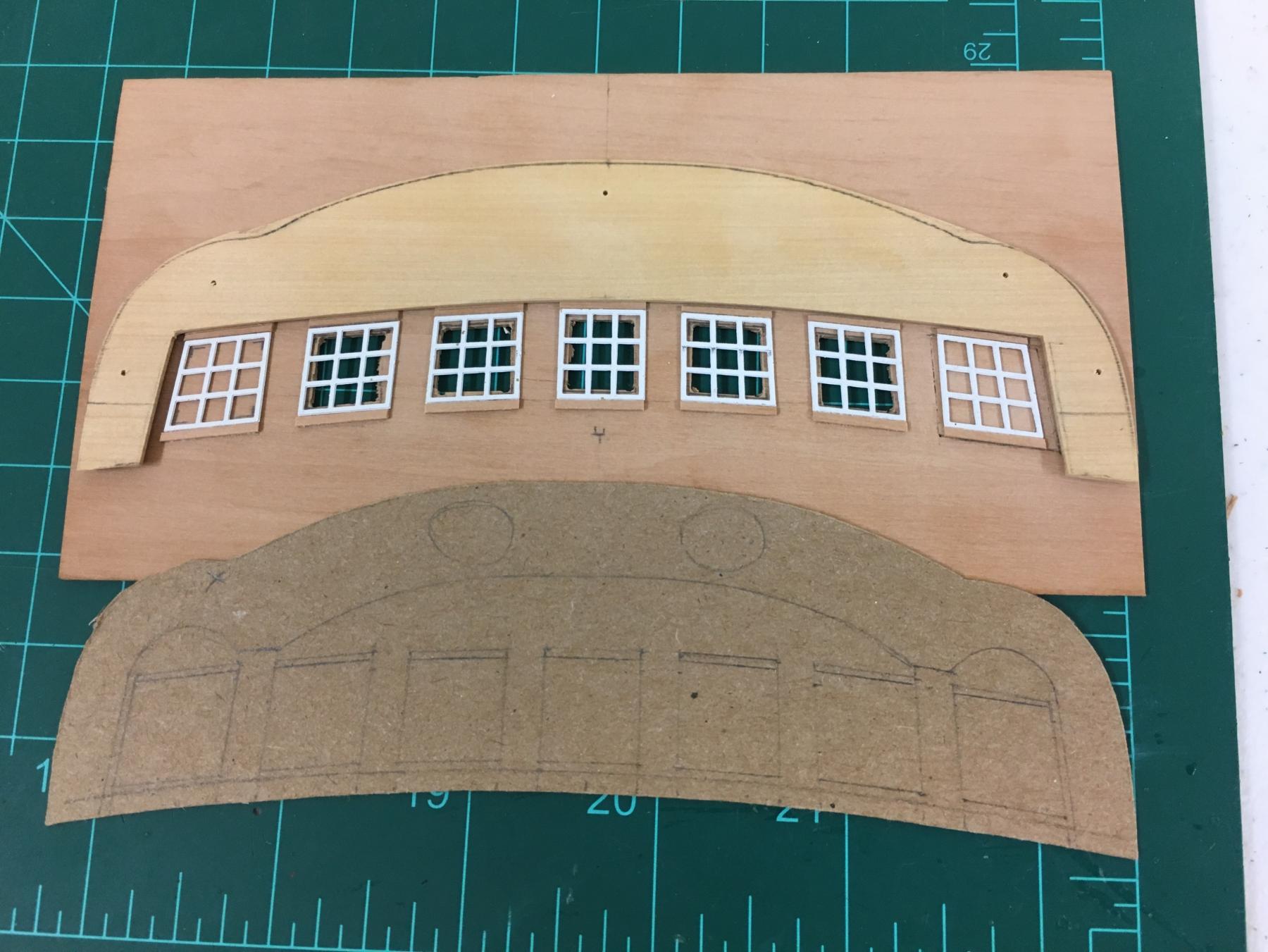
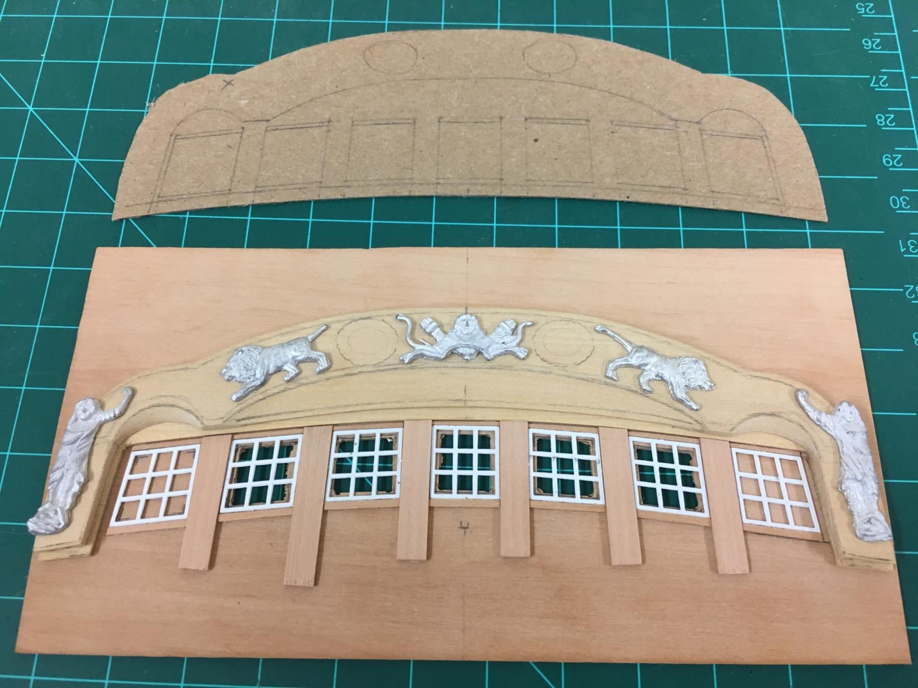
Nils - thank you for kind words, still going :-) The Stern I needed a bit of a distraction from coppering (which is still underway), and wanted to finally get cracking with the stern. This was something that I knew from the get go that would likely require some thought and tweaking. This is still work in progress and brings me up to where I am presently so I hope this works out OK. First off, a look at the plans/instructions and comparison to the AOTS series. Below is a comparison of the two, a scaled copy from the book, and the instructions, which are identified as being 1:1. There are quite a few differences between the two, and measuring the provided PE parts, the plans are not accurately drawn. Also looking at the photos on the kit box of the prototype, it just doesn't look right - too wide, lights proportionally too small, misaligned geometry etc. AOTS also identifies the outside lights as decorative false lights which I'll look to replicate. The look and feel of the AOTS version looks much better and authentic to me. I made a cardboard template that adjusts the projected profile to actual dimensions, this means increasing the height to account for the 15% slope of the fascia, and estimate changes needed to account for the horizontal curvature of the fascia. This lead me down the path of custom making the needed parts as I didn't the supplied parts would give me what I want. The downside of this approach is that I won't be able to use the supplied PE trim work, but thats a price I'm willing to pay as they PE parts don't even match the plans. A problem for another day. Next step was to determine how the windows/lights are aligned as the provided PE parts would save much time if they can be used. They differ slightly in size being a little smaller, but the biggest challenge is the difference in the profiles and shapes. I found that if the circled 2 lights either side of center are flipped and reversed through 90 degrees, it gives a more pleasing run of the profiles to my eye. The best placement of the PE parts was determined and tied as best as possible to the initial template. Places for these were then made at top and bottom with some cut 0.5mm sheet, and allowing for the columns (dry fitted only at present). Everything following was an exercise in compromise to get it looking 'right'. Once the placement of the lights was finalised, a fascia piece was roughed up to fit around the position of the lights to the required shape and everything trimmed to fit Fine tuning will be done later. The taffarel was cut out of 2mm sheet, and the various coves cut and shaped. Putting everything together together with the provided castings gave me the look and proportions I wanted which is enough for me to at least continue down this path. I do hope to try some of my own carvings but that's a decision for down the road... Next steps will be to pre-bend and laminate these parts, tidy everything up a bit and I'm sure identify some fresh challenges...