HOLIDAY DONATION DRIVE - SUPPORT MSW - DO YOUR PART TO KEEP THIS GREAT FORUM GOING! (89 donations so far out of 49,000 members - C'mon guys!)
×


Beef Wellington
-
Posts
2,249 -
Joined
-
Last visited
Content Type
Profiles
Forums
Gallery
Events
Everything posted by Beef Wellington
-
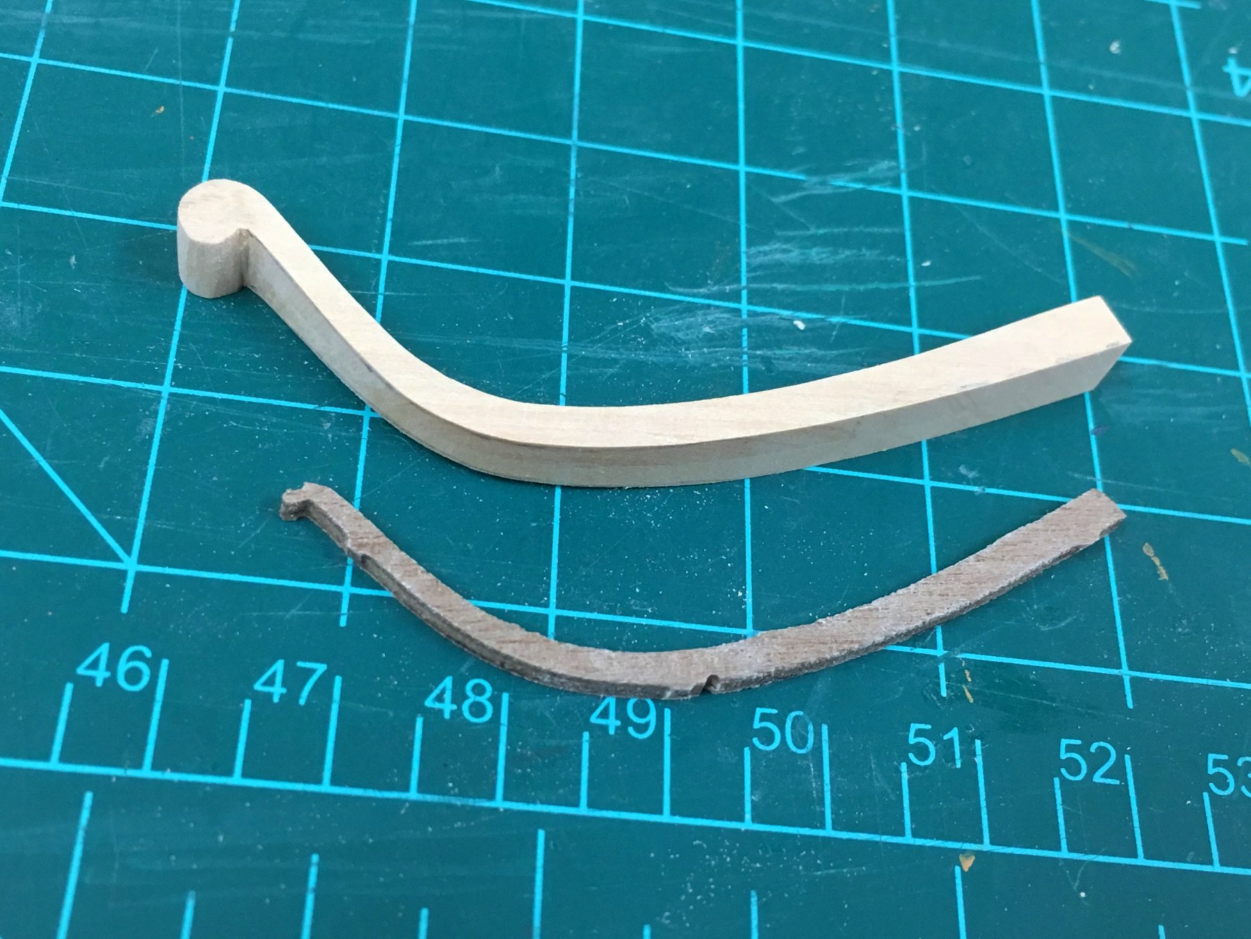
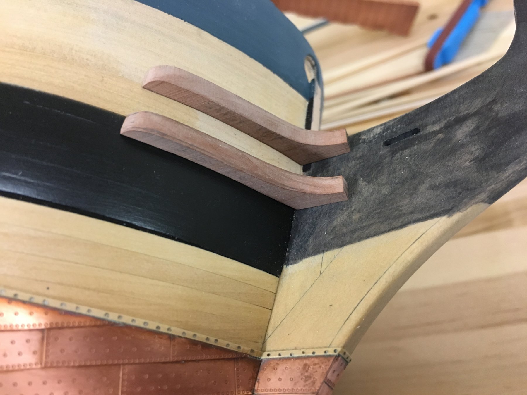
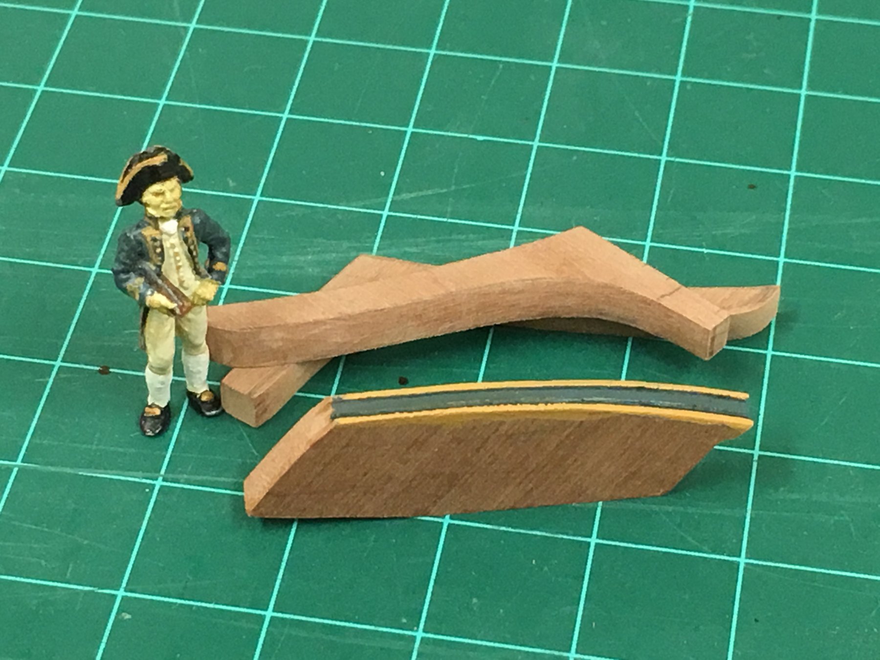
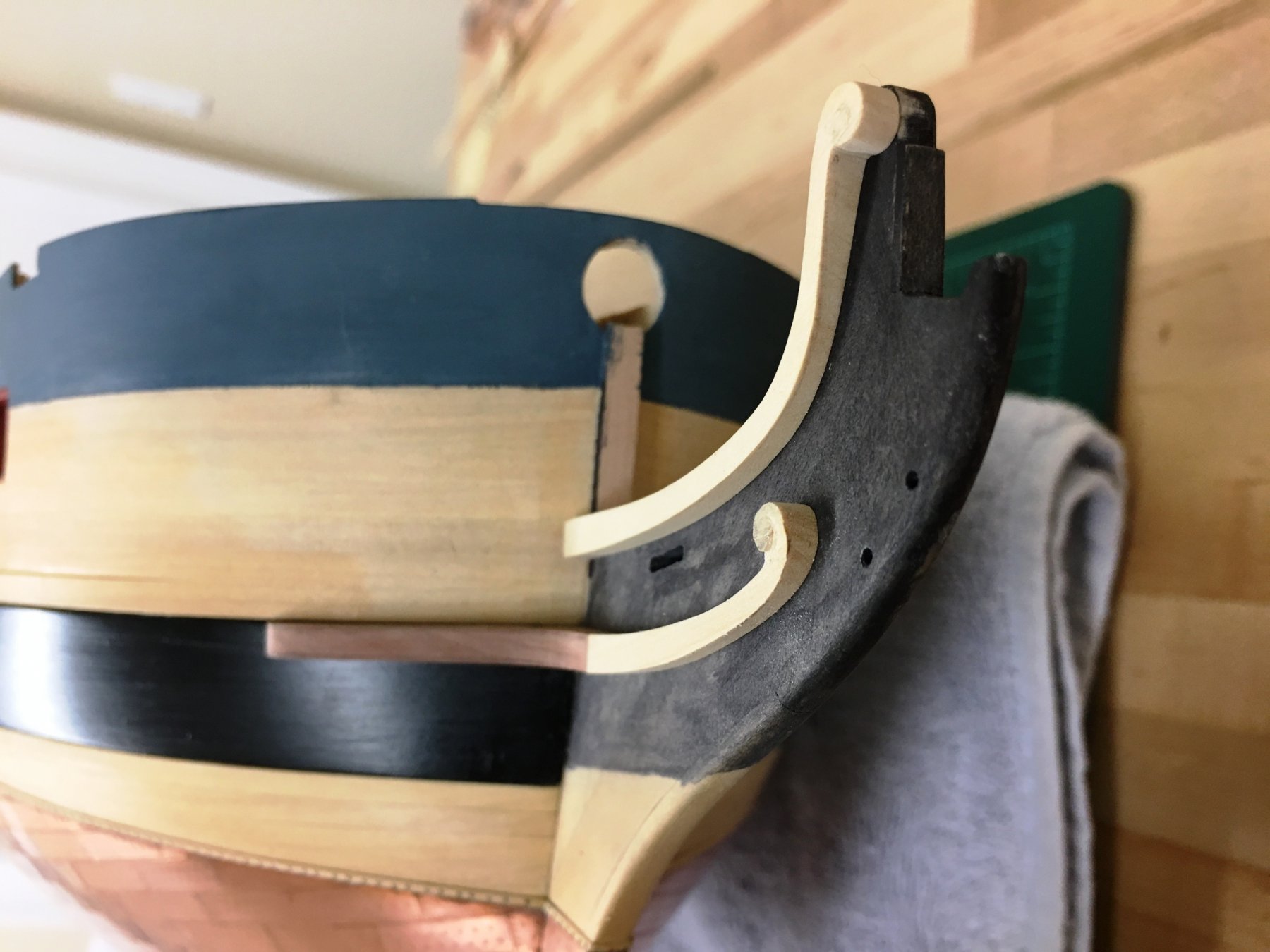
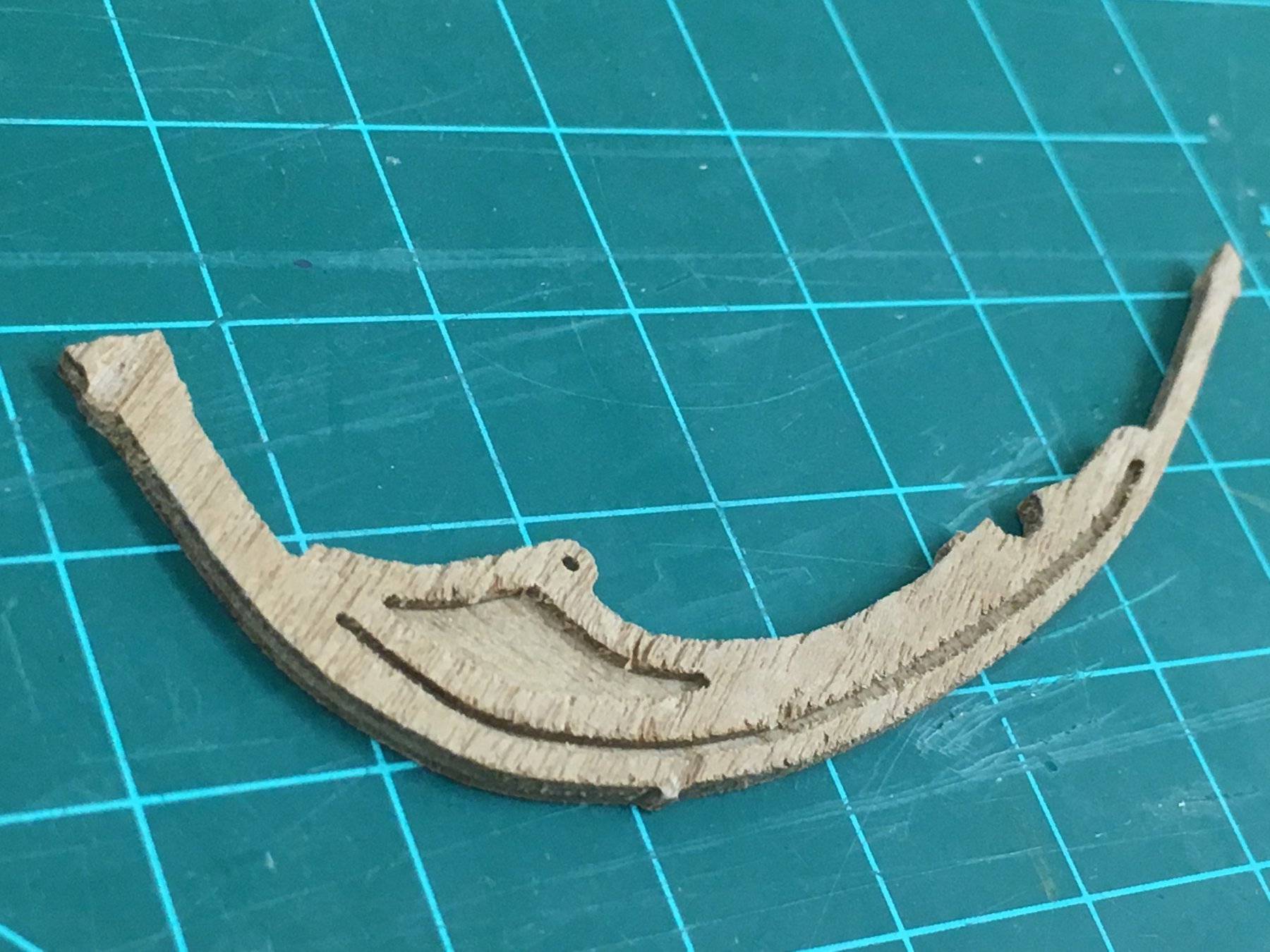
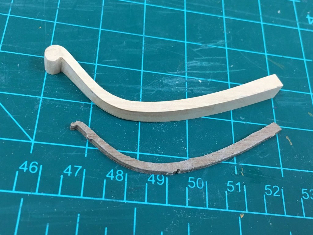
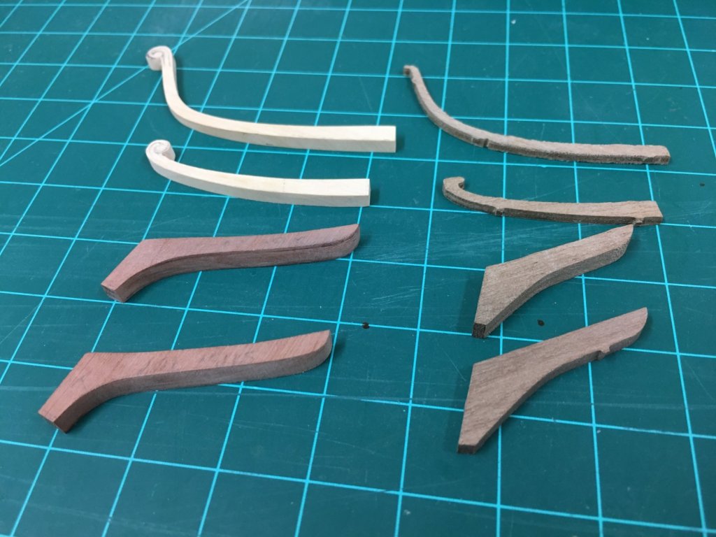
 Wow..Christian, Doug, Pat, Harvey, Carl, Tom, Wayne, VACorsair, Eamonn, and the likes, thanks guys for interest and the overly kind words. Narrative below will explain more, but think I've irrevocably stepped off the 'being happy with kit parts' ledge...this can only mean even slower progress...but perhaps more fun I know I'm bouncing around a bit so apologies for that, but continuing foundational aspects which seem easier with the ship careened over on a towel. Challenging Cheeks: The kit supplied cheeks are hair rail are not that great. The cheeks themselves come nowhere near to fitting the hull, and I'm pretty sure the hull form is correct. The only option was to scratch my own cheeks. Aside from the fit, they are also seem rather undersized. The next consideration was the hair rail and lower cheek, and decided to go whole hog and redo these as well. Given that there needs to be two of everything, I cheated and sparingly glued with PVA glue some 3mm sheet together and then cut to shape. The pieces were then separated using rubbing alcohol, and voila, 2 matching parts with the work of 1! These parts are still very slighty oversized to allow them to be fine tuned once other parts are made - necessary given I don't have any true plans to work from and that these pieces form quite a complex shape. Photos below show hair rail prior to separation. The difference in dimensions is quite evident to that appearing in AOTS which I used as a guide for the scratch piece. As a side note, the quality of the walnut parts are just not good, the main/false rail would need a lot a work to get presentable so suspect these will also be remade at some point. The cheeks themselves took a long time (days) to get right due to the angled concave curve and lack of plans. Pretty happy with the results, though the parts still need some fine tuning as the rails are a little thick still I think. I'm hoping to use a scraper to give a profile to the edges, and a quick test shows that this should work OK even for a quick test. This also commits me to what will probably be my first simple carvings on the scrolls, but that's for another day. Side by side comparison of scratch vs kit supplied pieces..
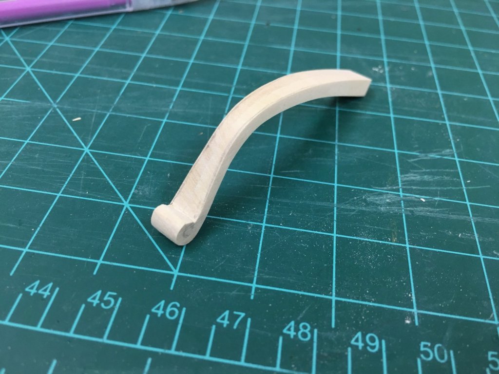


-
I love that Joe, really nice detail to add - its fun doing a little scratch work isn't it. It reminds me of the shortened school buses that my kids find so amusing....
- 136 replies
-
- 4
-

-
- caldercraft
- Cruiser
- (and 2 more)
-
I would assume they are bow thrusters, propellers within the hull to provide lateral steerage.
-
Bob, looking forward to learning more from you in this ship and especially the lumberyard kits, they look very nice indeed. Really nice clean start.
- 682 replies
-
- 2
-
-
- halifax
- lumberyard
- (and 1 more)
-
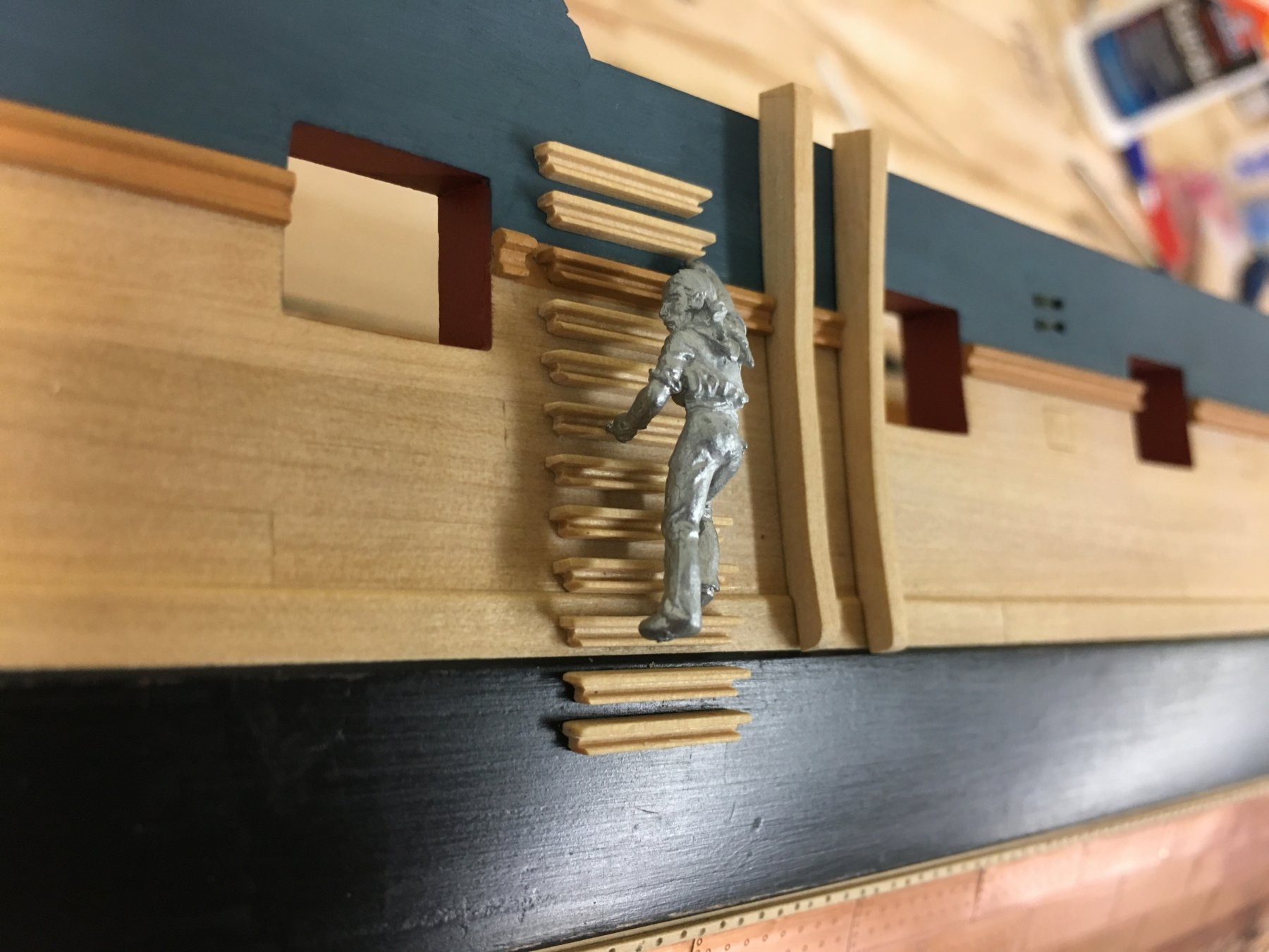
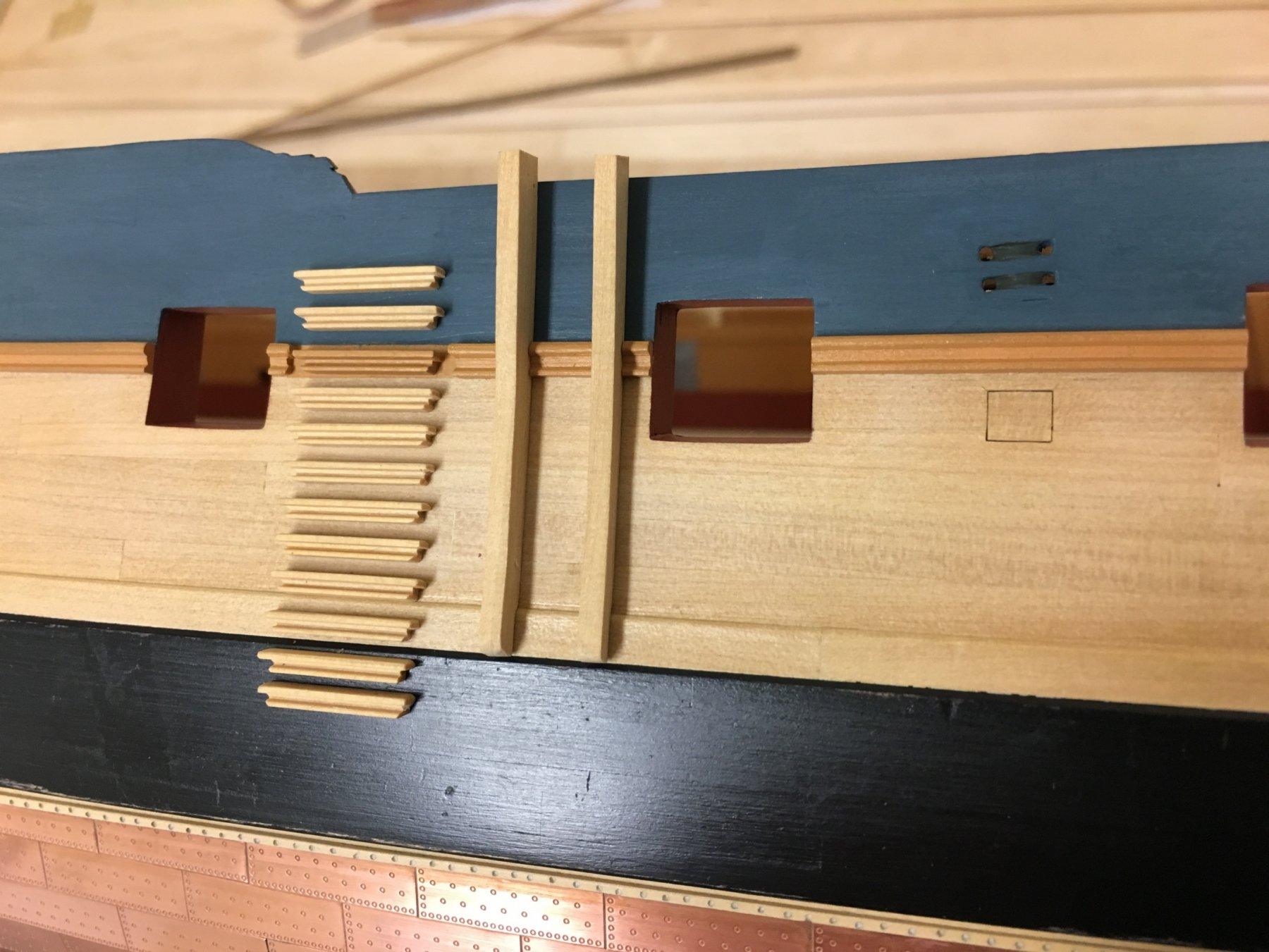
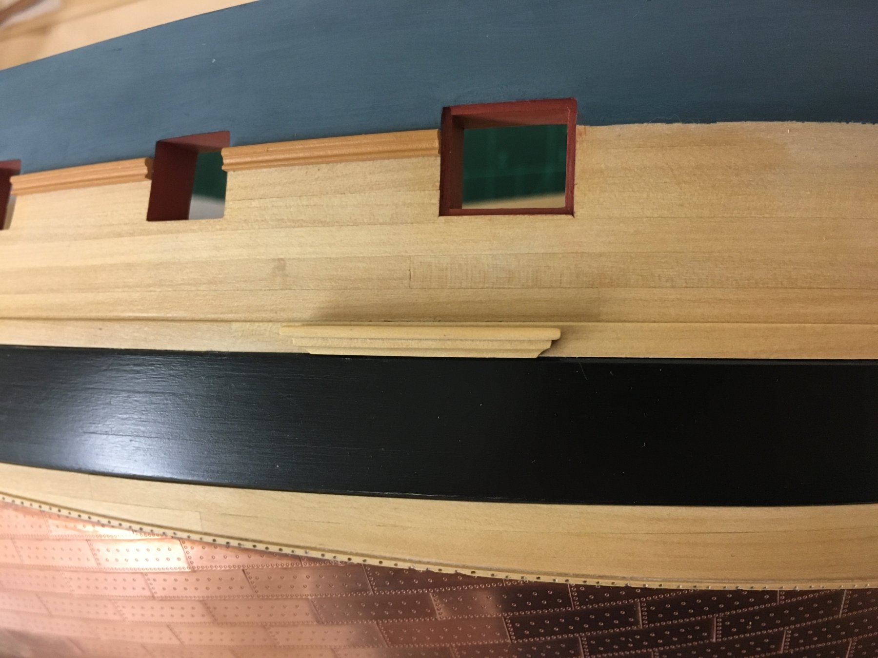
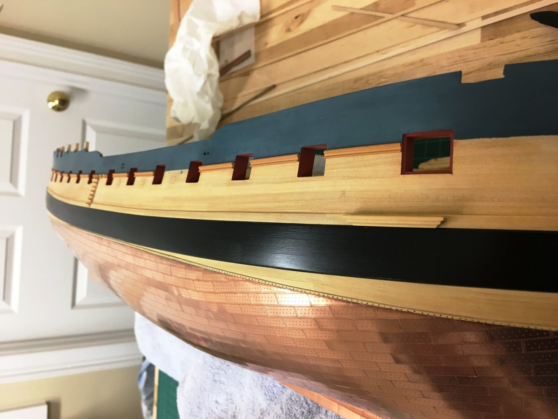
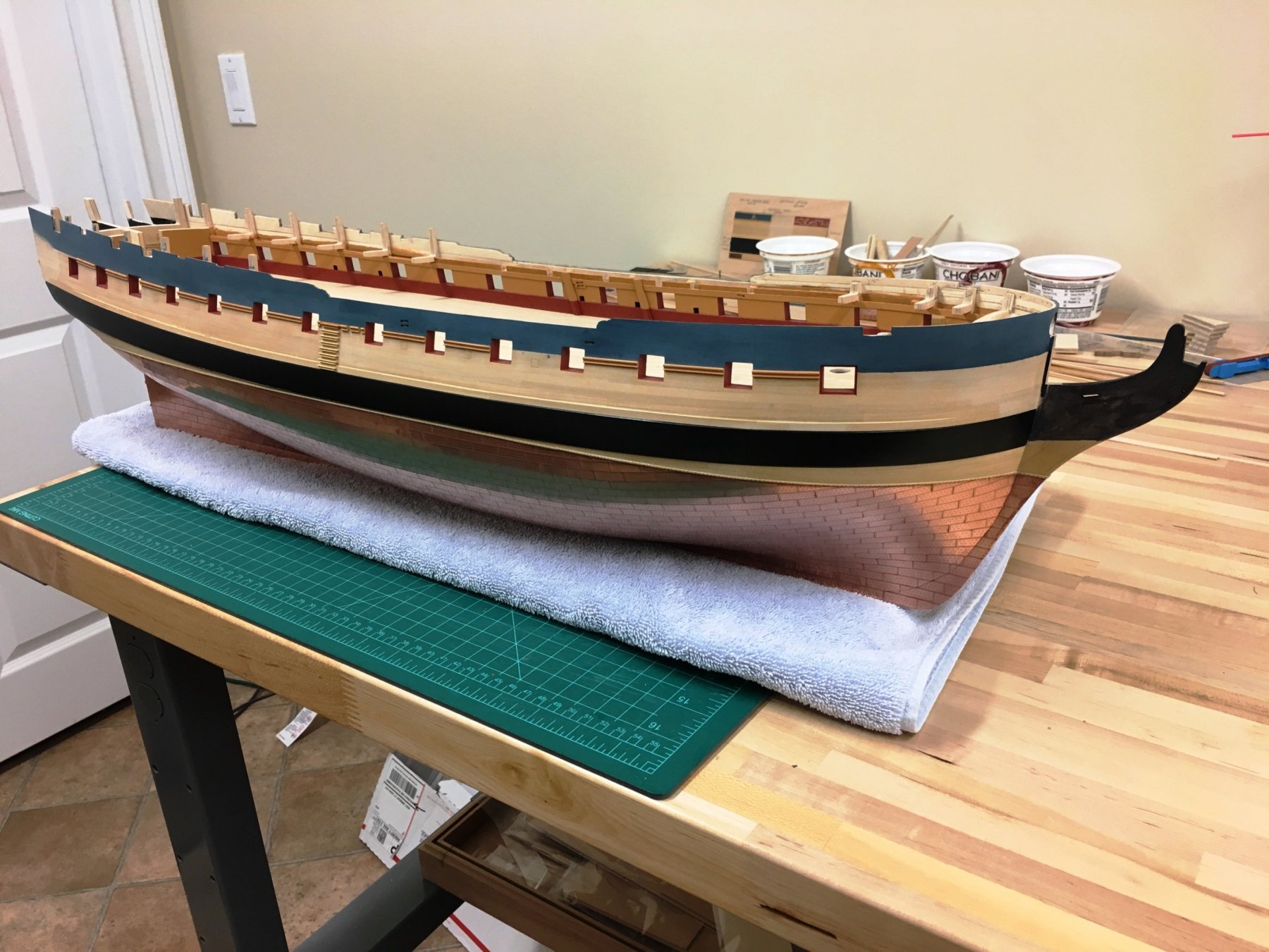
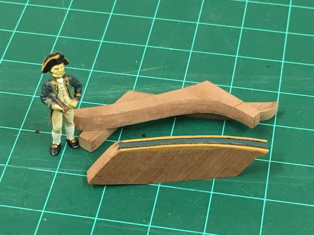
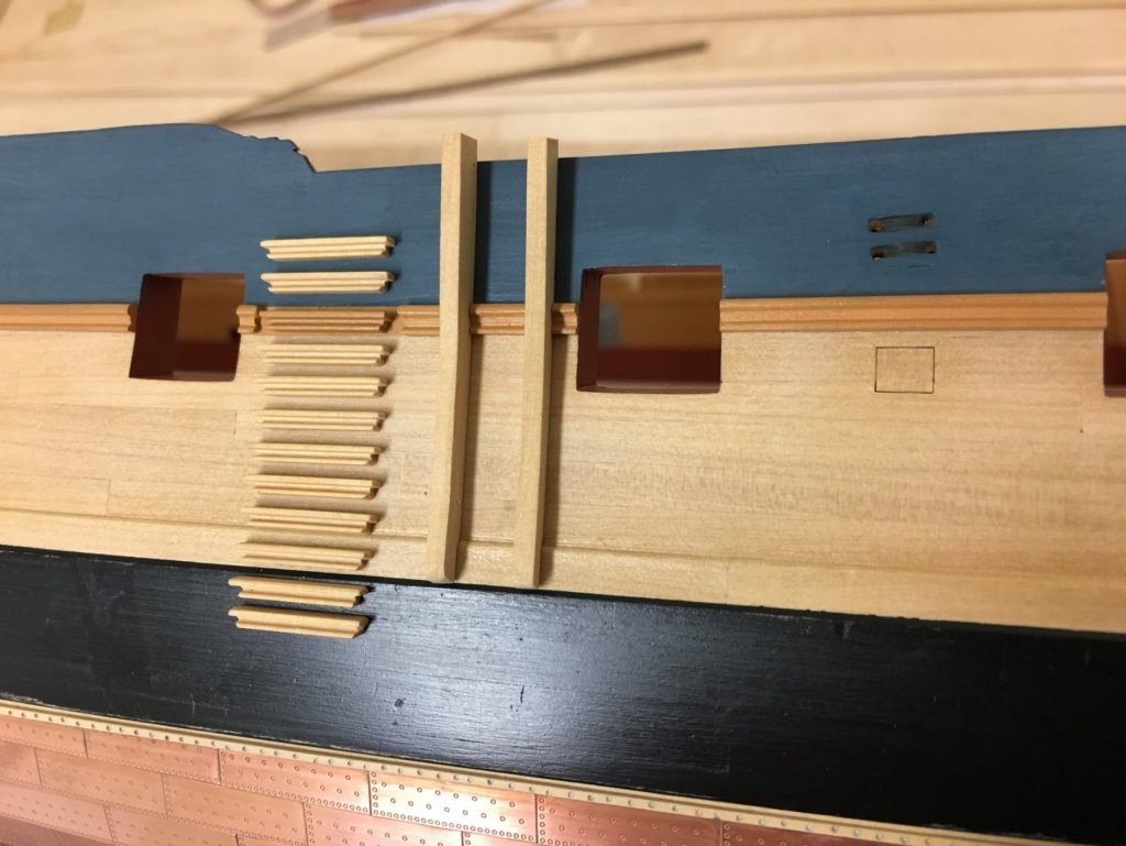
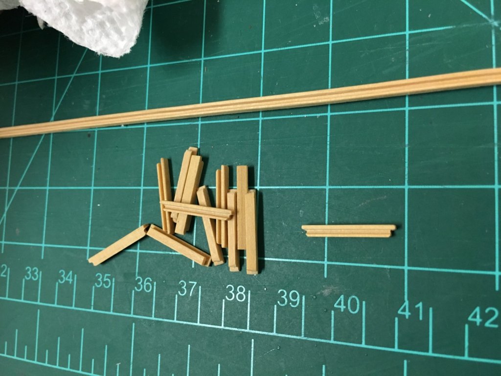
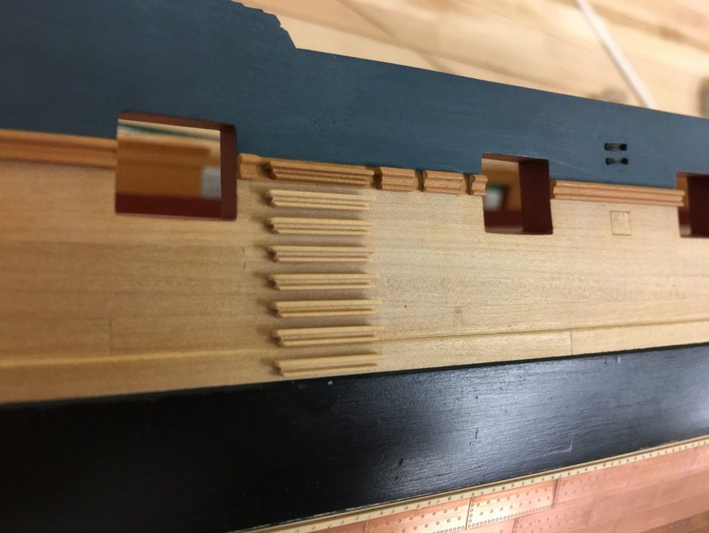
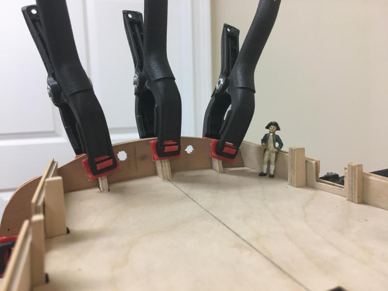
BE, Pat, Joe, Michael, Nils, Wayne, JPAM and the likes - thanks so much. Ron - I'm hoping to make it, would love to see your fantastic Diana in person, my challenge is always football/soccer as I coach my sons team and that takes a big bite out of weekends at this time of year. If I could just arrange a game in New London then I'd be set! Small update, I've been missing making posts but I have a little to share and hope pictures make up for it. Continuing to work on the more foundational aspects as I can. Paint has been applied to the upper hull - I used Tamiya matt XF-18 medium blue. I applied many layers of watered down paint and corrected larger imperfections, but left the slight imperfections from planking visible. I'm no painter and have limited experience with modern acrylics! Watering down the paint gives a nice smooth finish, but at the expense of surface uniformity - this should disappear completely once a clear sealer is applied so not concerned. I found that using a brush the undiluted paint dries so quickly that brush mark are inevitable. Lots of touchup to do which should be pretty easy, but I want to get a protective coat of poly onto the boxwood to reduce the risk of mishaps. The waist rail has been applied on one side and the side steps added. I left gaps for the fenders, after having already cut these roughly to shape - using boxwood of course adds the number of pieces that need to be fabricated to keep consistent. I wont attach these until later. Steps were made using 2x2mm boxwood strip and a different profile scraper to the side molding and then cut length and shaping the ends. These hopefully give more of an impression of the fine molding as keeping that to scale was just too much for me. The upper and lower 2 steps are not glued yet. I think they pass the scale test with the assistance of Able Seaman Lewis. I've also made up the anchor lining bolsters, not identified in the kit plans but approximated from AOTS and TFFM. And the usual 'all over' shot of where things stand..


-
Hi Christian, a very nice fix on the hole for the seats of ease. This seems to be a challenging area but sure it will look great. The other difference/deficiency I see with the kit is that it seems to completely ignore a seat of ease in the back corner of the false rail and the ships side, simply leaving a large triangular hole which looks odd. Are you thinking of adding those as well? Your styrene yards are a much better solution to the really clunky white metal parts and look so much better. Really nice work!
-
Out of breath reading the last installment, so much to consider, the only think missing from this rip roaring tale are a couple of gypsies thrown in for spice. I was devastated to see the issues with the log (seems to be every time that there is an upgrade) and want to say again how appreciative of your time and effort I, and I'm sure everyone, is to keep this jewel of a log alive and kicking. So much great information, tips and tricks...I love the shot of the great cabin deck, I'm assuming its not accessible at this point though?
- 366 replies
-
- 6
-
-
- pegasus
- victory models
- (and 2 more)
-
Awesome! Disappointed I couldn't 'really really like' the Priory beer photo
-
HMS Sophie
Beef Wellington replied to ivica70's topic in CAD and 3D Modelling/Drafting Plans with Software
Hi Ivi, really nice work. I'm curious about the stern cabins, do they appear at all on the plans or elsewhere. I know this set-up is usual in larger ships, but they seem so very small on this vessel that I question their utility and especially considering the space premium to accommodate the crew. -
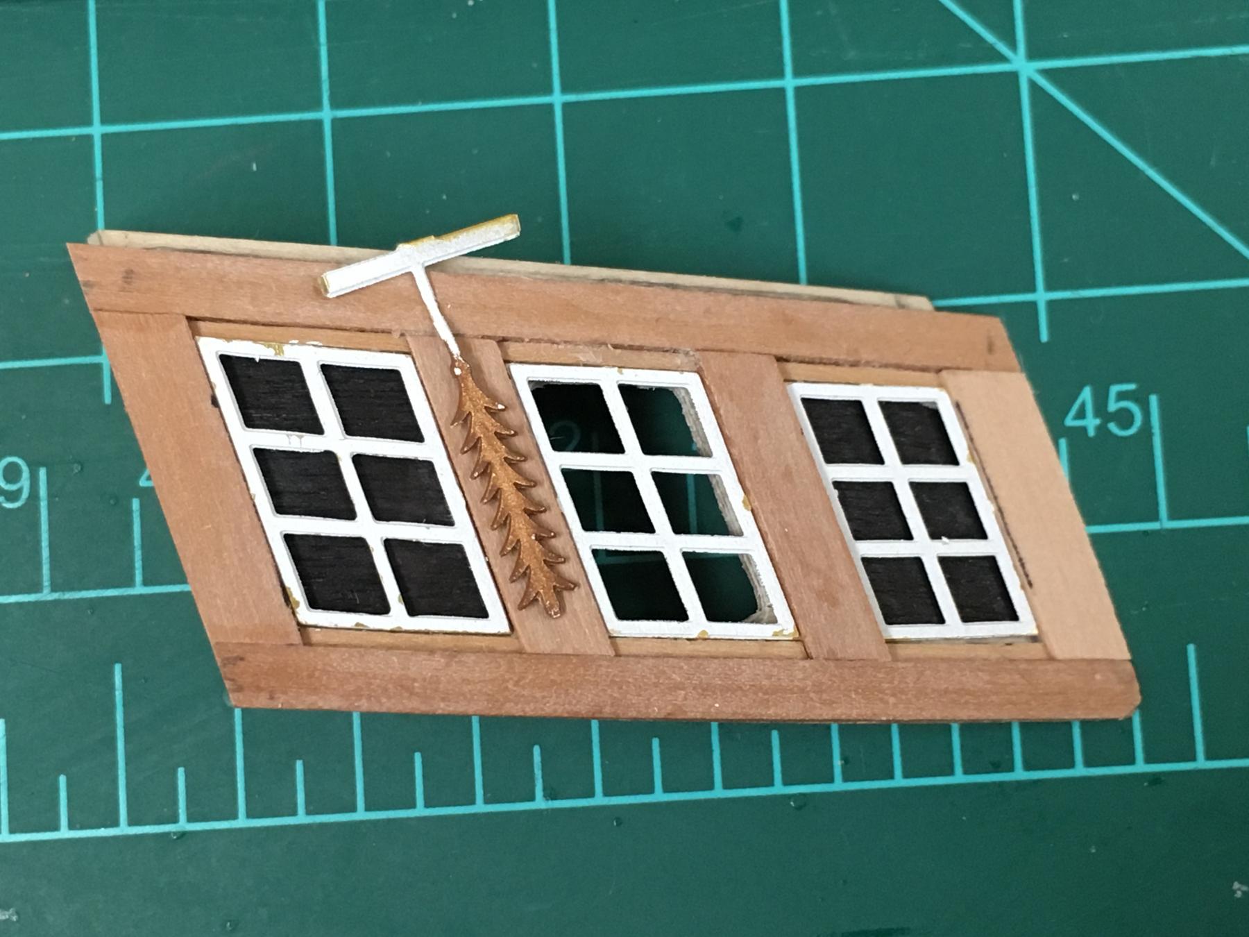
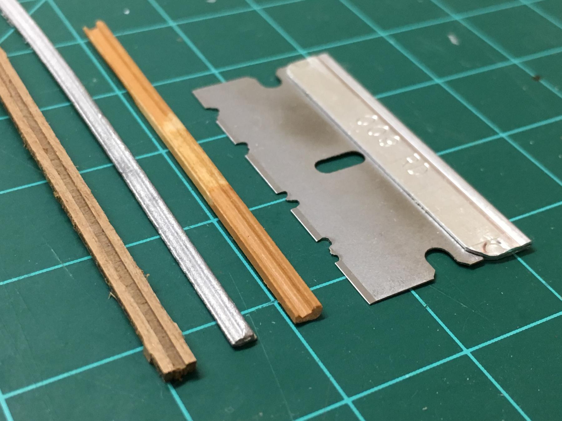
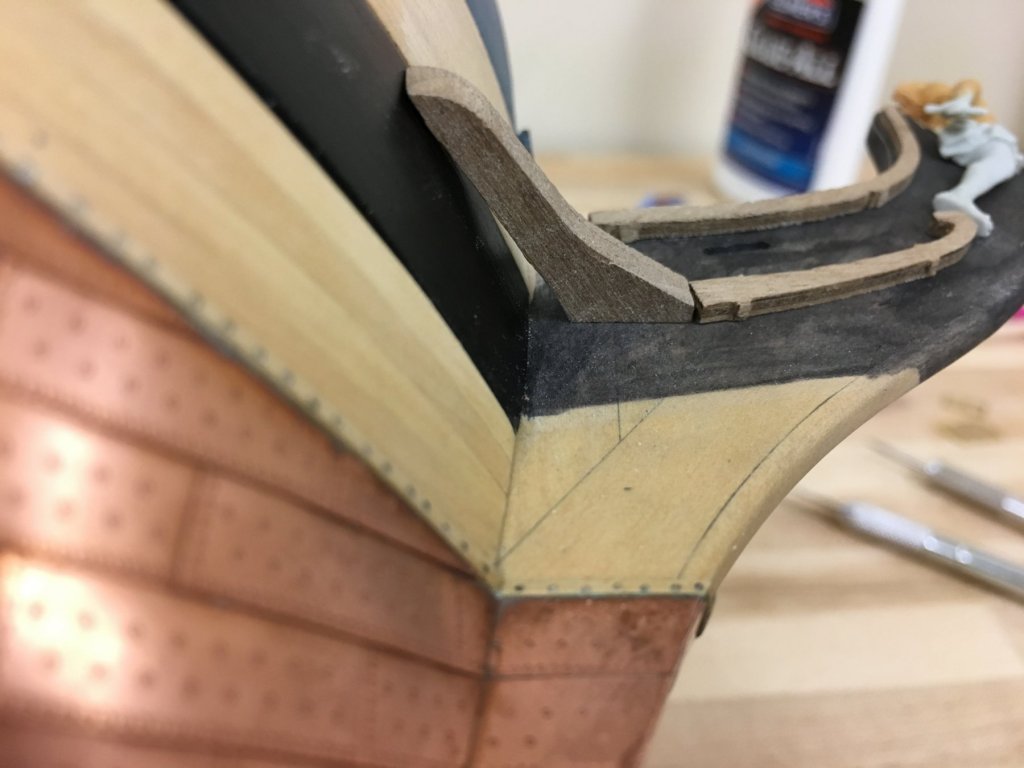
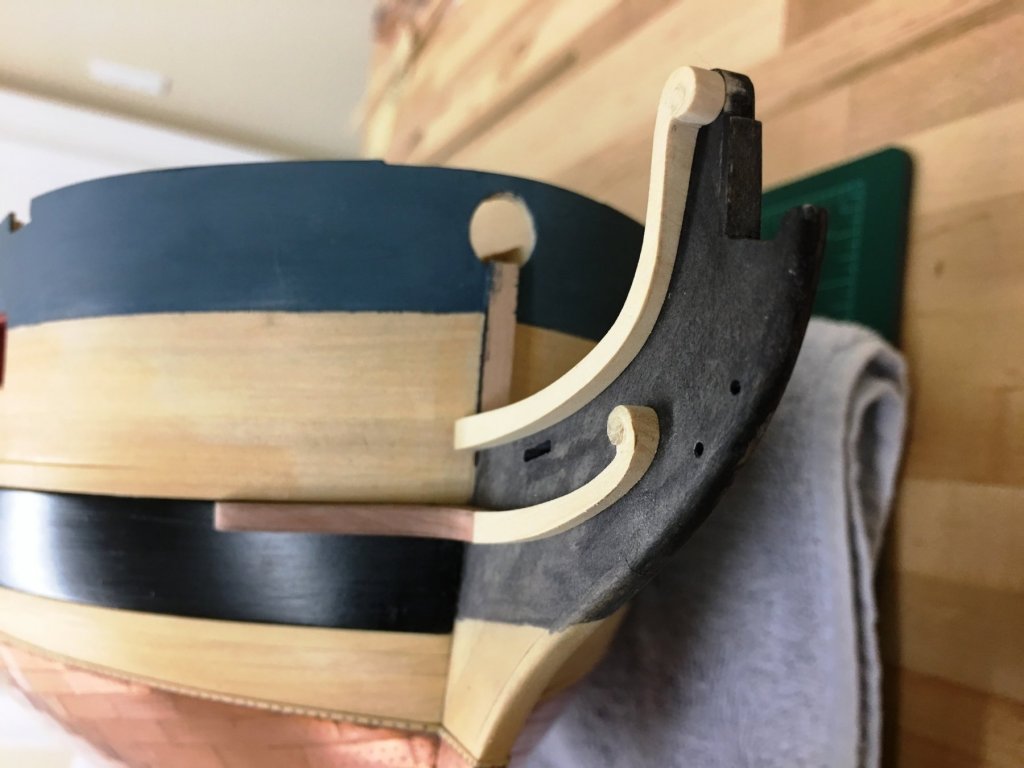
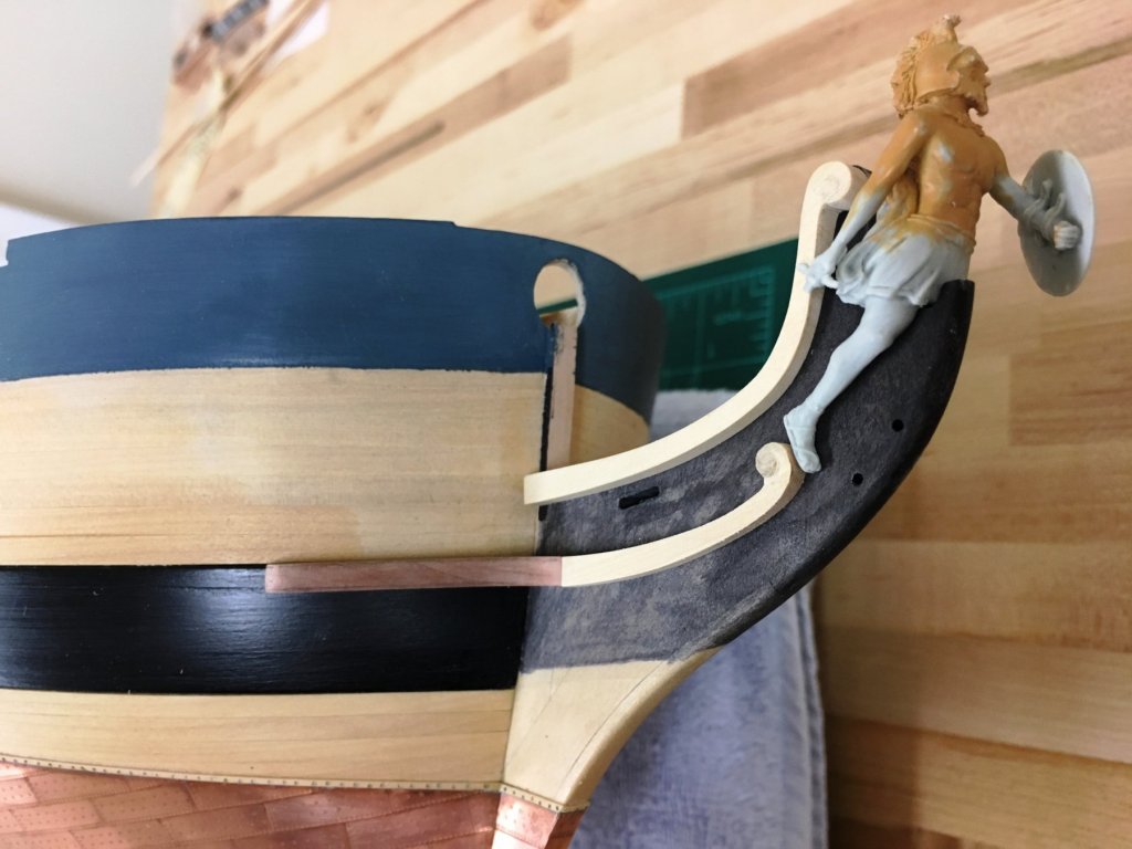
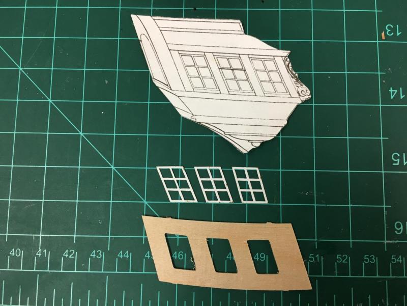
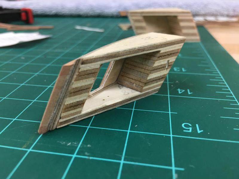
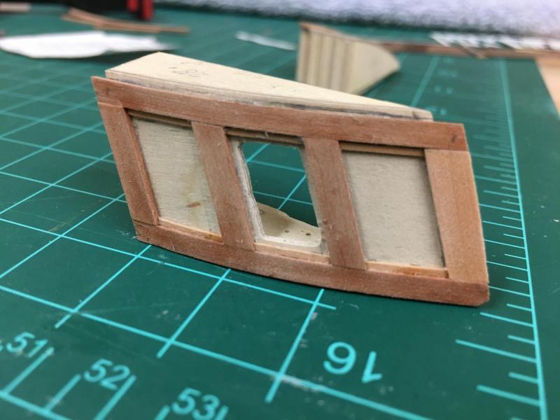
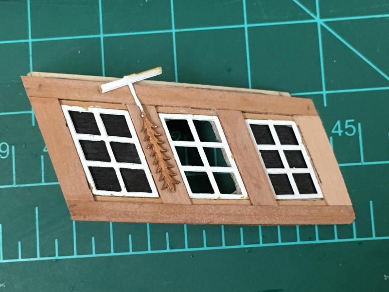
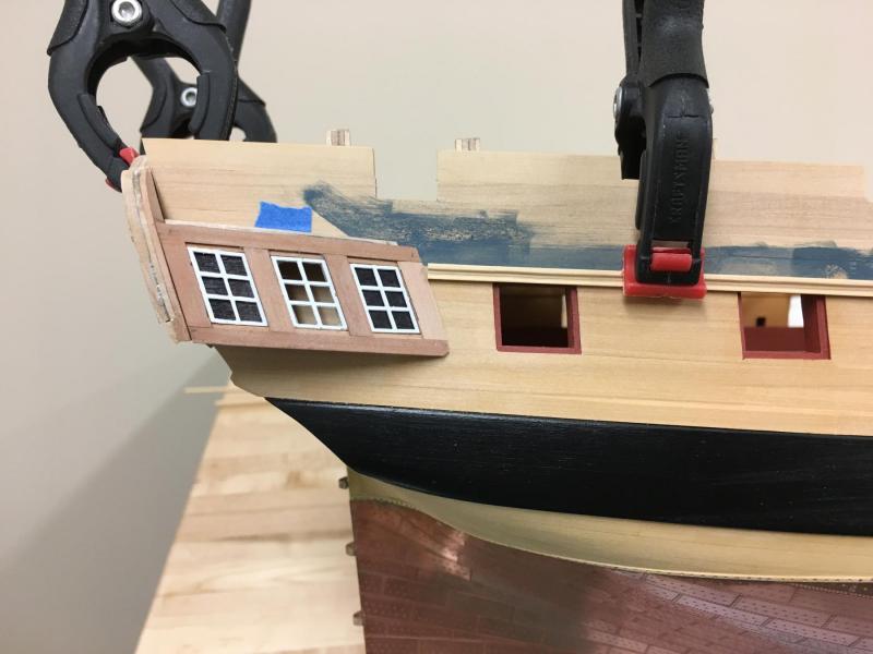
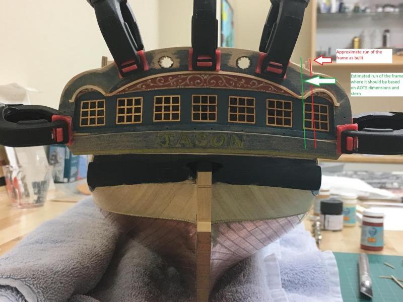
A quandry with the Quarter Galleries Thanks all for the continued interest. Slow progress continues, the usually slow pace has also been impacted by me losing my job late last year which theoretically meant I have a lot more time on my hands, but has unfortunately in practice sapped my enjoyment to some degree. This was coupled with some continuing challenges with the copper finish. I've forced myself to stand back and leave alone to later date so have moved on... The quarter galleries seem to once again present quite the challenge I think to look right. The kit instructions are very simple, attach the quarter gallery panel to an upper and lower former, then attach the lights - but do not identify which is which. Analysis of the provided PE lights show similar problems to the stern lights; they are slightly too short, and their geometry is not quite right but think these can be accommodated. Each light is a slight different height, but think CC went the wrong way the one that is tallest should be shortest and vice versa. Sure this could have worked, but wanted a little more control over the outcome to fine tune as I go. I decided to frame up the actually gallery to be more robust so built up the front and back with some spare ply. Shaping was done before attaching my own cut fascia piece cut from some extra 1.5mm ply - I did this so I could represent the fore and aft lights as false lights (as per AOTS) similar to the stern fascia as I've decided to stray away from the modelling ideal and represent as close as possible to actual practice. The geometry of this arrangement seemed to boil down to two key elements. The fore and aft planes of the gallery should be parallel when viewed side on, and the lie of the gallery should be parallel to the wale. Allowing for the slight tumblehome and compromising the above objectives together with the actual shape of the lights brought everything together by trial and error. The build up on the fascia was done in exactly the same way as on the stern fascia. I pre-bent the horizontal strips vertically first to ease attachment. These still require a little fine tuning. One note, I decided to used 4mm strip for the columns rather than 3mm which is probably closer to the plans and AOTS. The reason for this is that the PE decorations are approx. 3mm wide and I think would look awkward - don't think this minor change affects the overall look too much. As a diversion, I started to experiment with making a scraper to develop what will hopefully one day be moldings. The razor blade was simply cut with a dremel and the narrowest cutting blade I could find (AND PROTECTIVE EYEWEAR AND LOTS OF CARE). The result is far from perfect (lots of tries to find one that works) but its amazing how imperfections can be dealt with by simply taking your time and focusing on the end result - I was pleasantly surprised at my first attempt. I much prefer the look to the supplied white metal supplied for the stern, and the provided cut walnut for the sides. Putting everything in place allowed me to check alignment, and I was happy with the way things turned out. Aligning with the still dry fitted stern fascia and placing the side molding approximately where it should be showed that this appears to cut the quarter gallery mid way through the top pane - pretty much where it appears in the AOTS diagrams. To my eye, the compromises seem to disappear except upon close inspection and are less noticeable in person. Now the prototype is done, need to do the port side...

-
Looking spectacular Bob, rigging included.
-
Thats looking good Rob, especially like the beak and the adjustment you made. Curious if you've placed the bulkheads into the keel former, I know I and other had issues where there is not enough keel below the bulkheads. Options are to build up the keel former or reduce the bulkheads, the former option seems a much easier way to go. Great progress!
-
Actually its even worse, the volume increases by factor of 8 (2 to power of 3)...
-
Fascinated to see this one get going Gaetan, pictures please!
-
John - it would have gone sooner had I seen your post earlier Looks like one beautiful kit and they seem to be like gold dust now...
-
That deck looks great Mark. Its still a mystery to me the marking out of the curved planking but looks awesome. Are you going to place individual planks or are they 'one piece'? If individual, I wonder if its possible to alternate planks from stb and port sides so the grain of the wood differs so it doesn't look like its cut from one piece. Very jealous of that deck Mark
-
A very interesting project indeed, definitely want to follow your progress.
- 2,697 replies
-
- 3
-
-
- heller
- soleil royal
- (and 9 more)
-
Hi BE, I think I understand your conundrum....I wonder if this is one of those situations where what happened in practice vs what looks good on a model diverge? It seems logical to me that they would run outside of the other rigging in practice, but this may then cause them to foul when no sails are present which could look a little odd.
-
This is great thread, something I have done a lot of thought and analysis into as well. One correction to #9 above though, copper is naturally pinkish and it is this colour that is seen when newly shined or subject to repeated abrasion. Copper gradually 'browns' when weathered naturally but it can develop a greenish patina in certain environments especially when constantly wet in salt water environment betwixt wind and water. I think Dafi's first picture above is a perfect illustration of this. Other thought on this subject is that it is once again in the eye of the beholder. Scaling down seems to be as much an art as a science so its probably not worth while obsessing over the nails. Good example is paint colour, it seem back looks too 'black' when scaled , so people often use a very dark gray. Glossy paint is much more distracting at smaller scale so people tend us a matte or a satin when a semi-gloss may have been used in practice.
-
Looking really beautiful Mark, really coming together now. Can't imagine how heavy she must be now...
- 652 replies
-
- 1
-
-
- royal william
- euromodel
- (and 1 more)
-
HMS Victory by willz
Beef Wellington replied to willz's topic in - Build logs for subjects built 1751 - 1800
William, just found your log and your Victory, wow! I love the idea of the using the woods to show the Nelson chequer cirrectly, but your execution is just amazing. Definitely want to keep following your progress and your great ideas. -
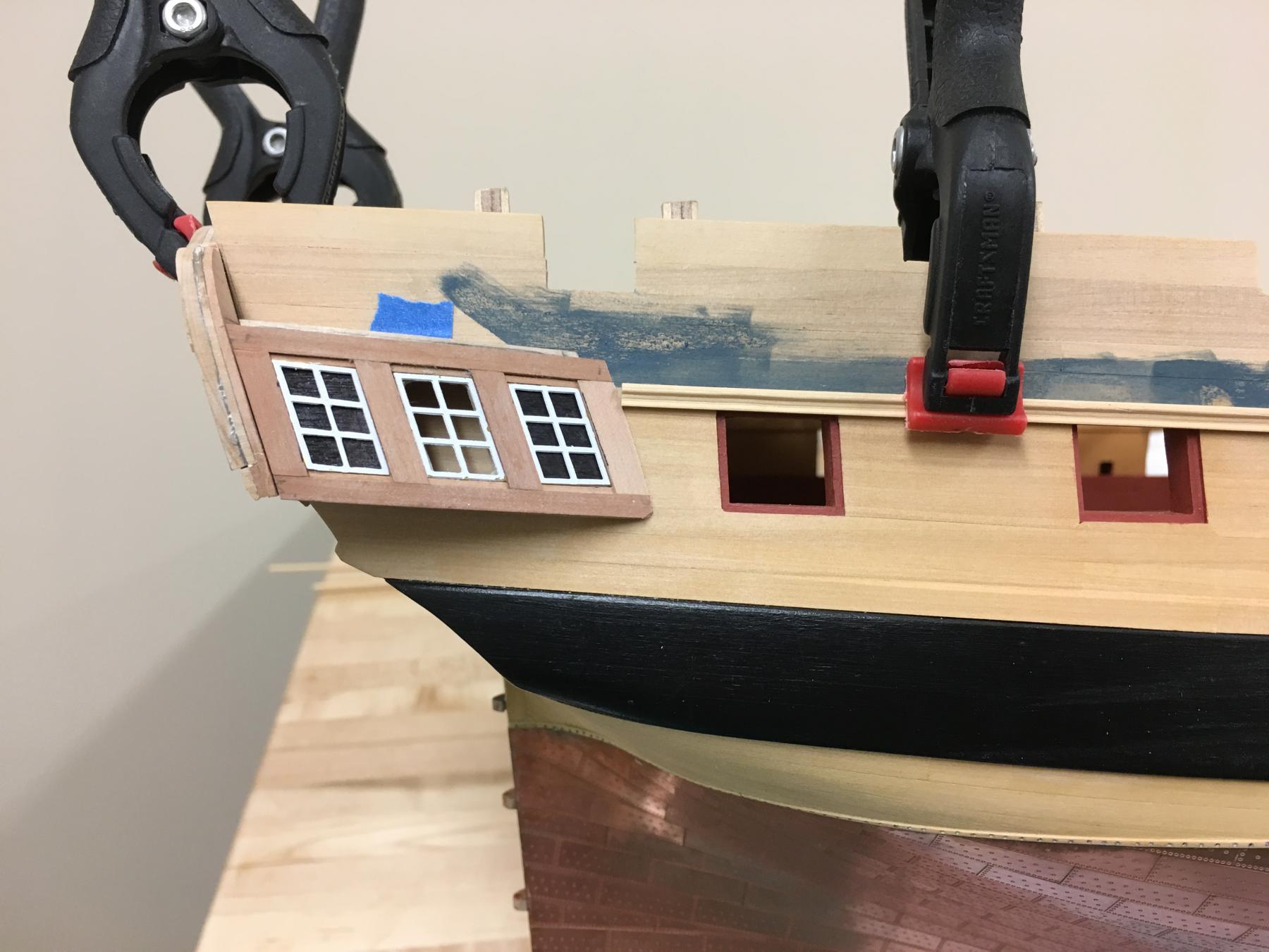
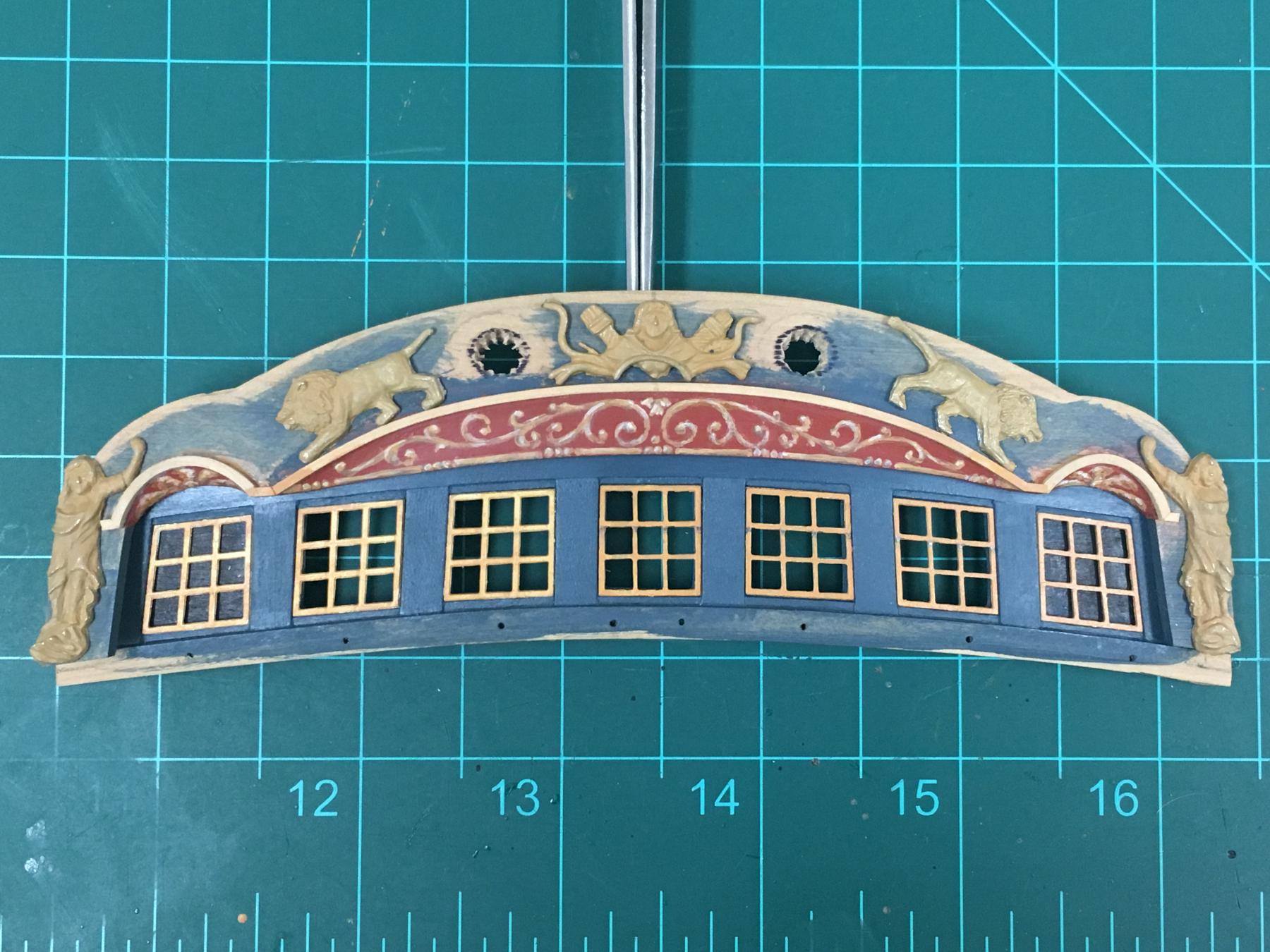
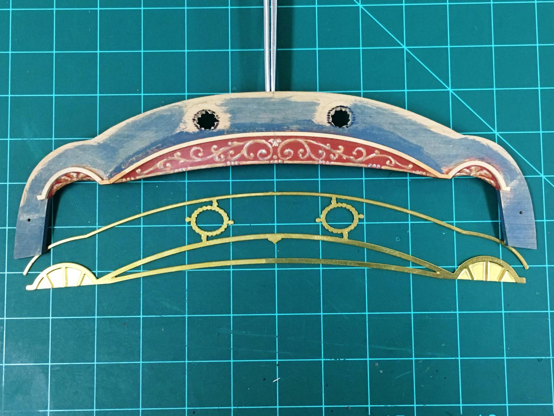
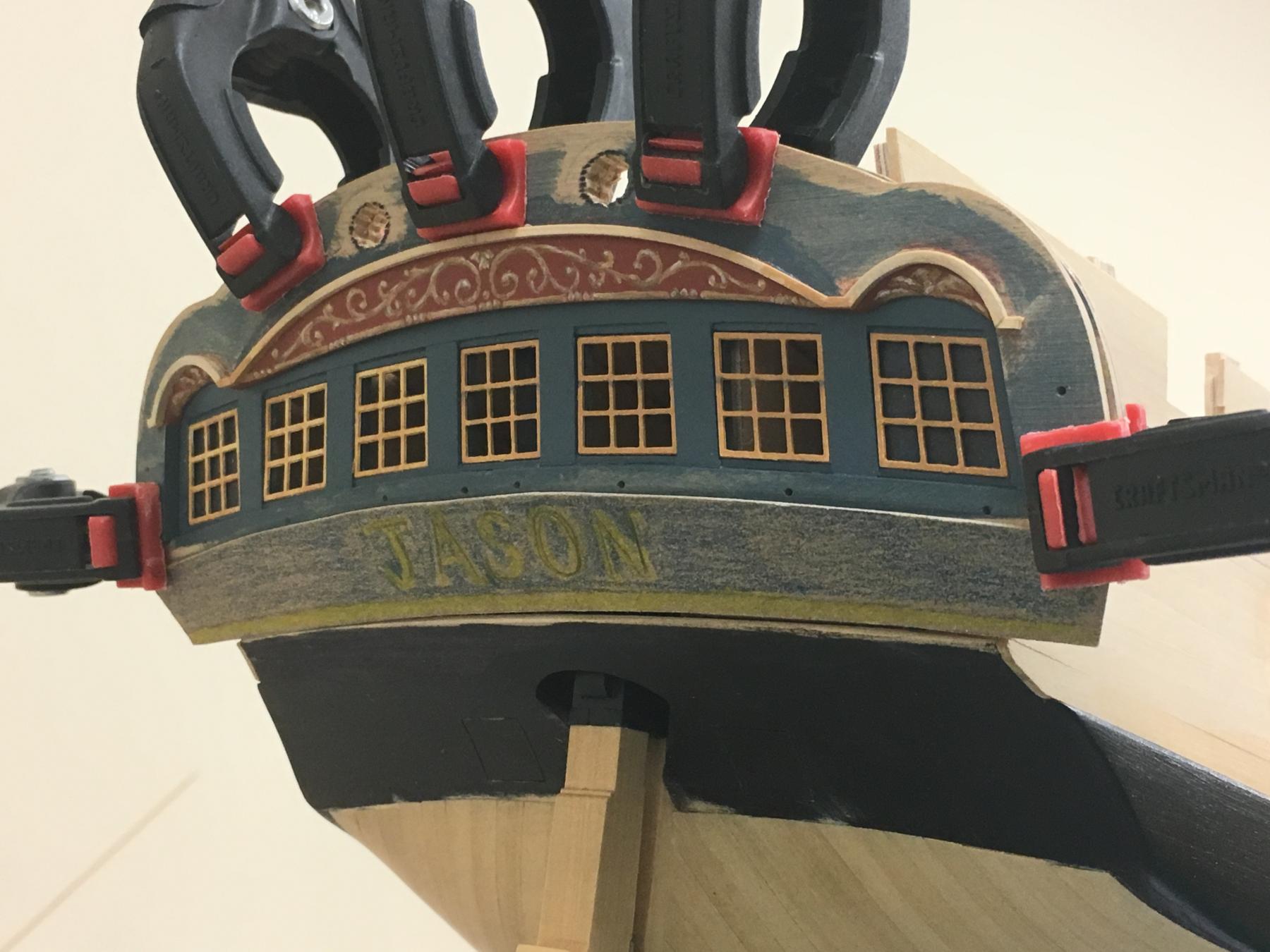
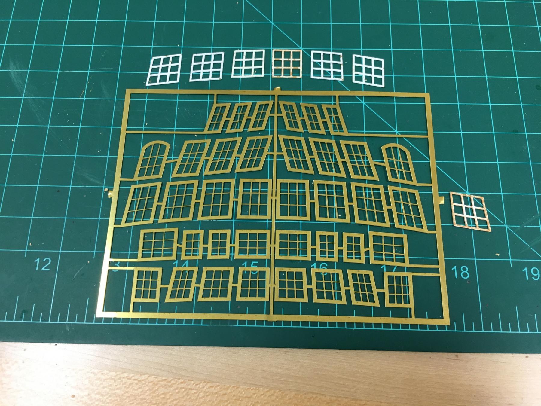
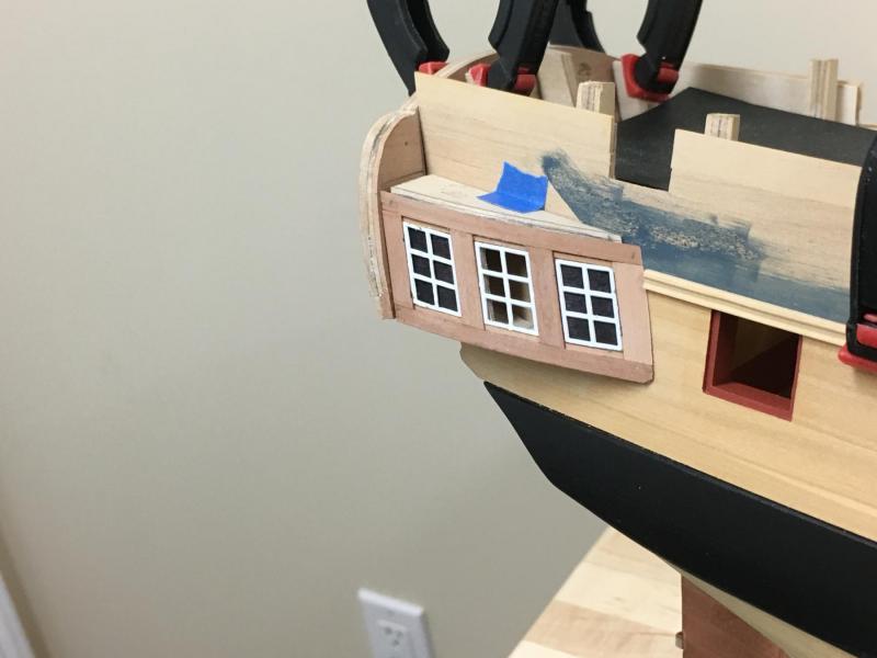
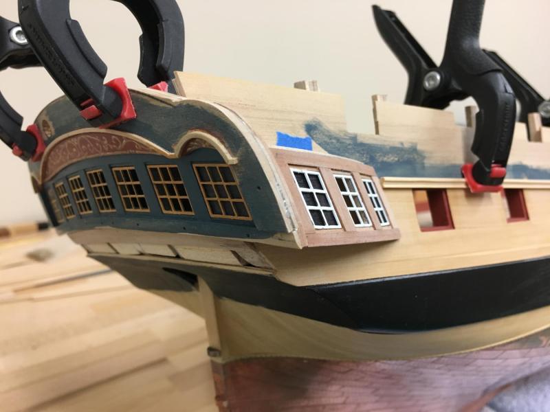
Here's an update just for you Sjors... Since finding out the Aggy lights are not an option been trying to figure out where I want to go with these. I realized that the thickness of the mullions of the supplied PE parts was a major reason why the lights just did sit well to my eye. Plucked up the courage to thin these down with the smallest file I had. The photo below shows the filed down ones at center and on the right, original on the left. I stopped here for now at the risk of taking too much off and ruining these pieces reserving the right to possibly thin a little more after I've looked at them for a bit. I deliberately left the top 'mullion' thicker to simulate the single sash. Definitely would appreciate others opinions and suggestions here.... I shaped some 1x1mm box for the cove moldings, the trickiest to get right were the outside coves as the curve is so tight. Left the strip to soak for a day and then steamed with an iron over a cardboard tube left over from some rigging line which was about the right shape. I'll try to shape this a little with a scraper at a later date. I placed the various cast ornaments for now to get a sense for alignment even though I would like to try and carve some replacements and was pleased with the way these sat together, my eye being very sensitive to proportions for some reason. I'm happy so far. Something else just hit me as I was reconciling various dimensions and it also explains discrepancies in the kit plans and supplied parts. I'm estimating that the width of the bulwarks at the stern is approx. 10mm larger (5mm each side) in the kit than is identified in the AOTS and possibly explains why the supplied stern fascia is so wide - for comparison below you can see the kit supplied PE versus my version.. I wanted the proportions shown in the AOTS and you can see the rough misalignment I don't think that this will be that noticeable so I'm not proposing to do anything else here. The angles look rather off in this view but to the eye it is much less jarring. Lastly, a slightly more forgiving angle showing the expected results of all the compromises, overall, I think this may just work. Obviously lots to do yet and a few more tricky problems to solve...including some carving.


-
Not an update as such, but the answer to a previous question. Had lots of dicussions on the stern lights, and one consideration was the use of PE lights from the Agamemnon kit. Sjors very kindly (thank you Sjors!) sent a spare set he had. Unfortunately, these don't look like they are an option. They are certainly more nicely crafted than the Diana ones, with the mullions being much thinner. Photo below shows the comparison (my PE frames are showing the signs of colour experimentation) There are 7 lights on the Artois frigates, 8 on the Agamemnon The sizes and proportions are not really close enough, being larger on the Aggy