Beef Wellington
-
Posts
2,249 -
Joined
-
Last visited
Content Type
Profiles
Forums
Gallery
Events
Everything posted by Beef Wellington
-
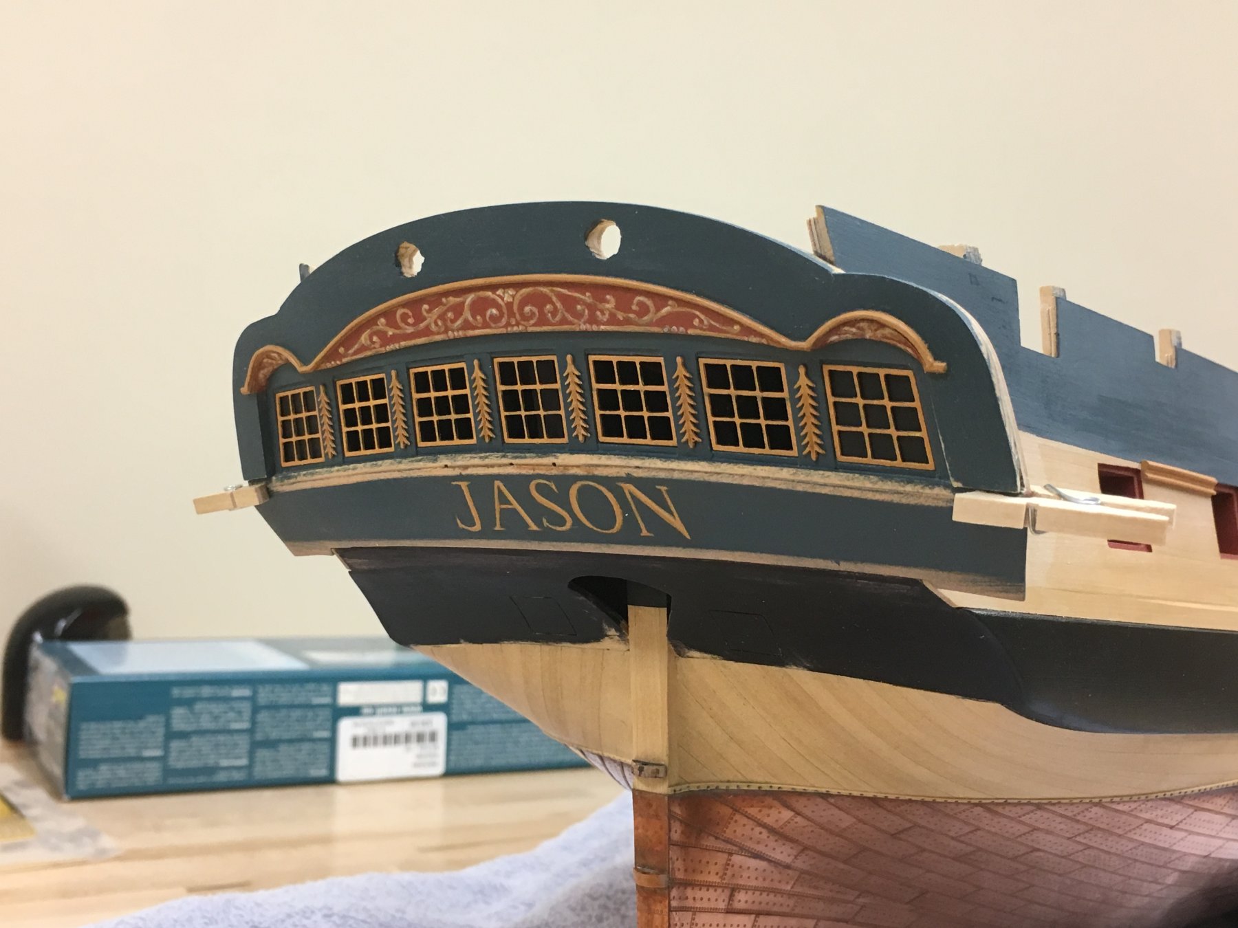
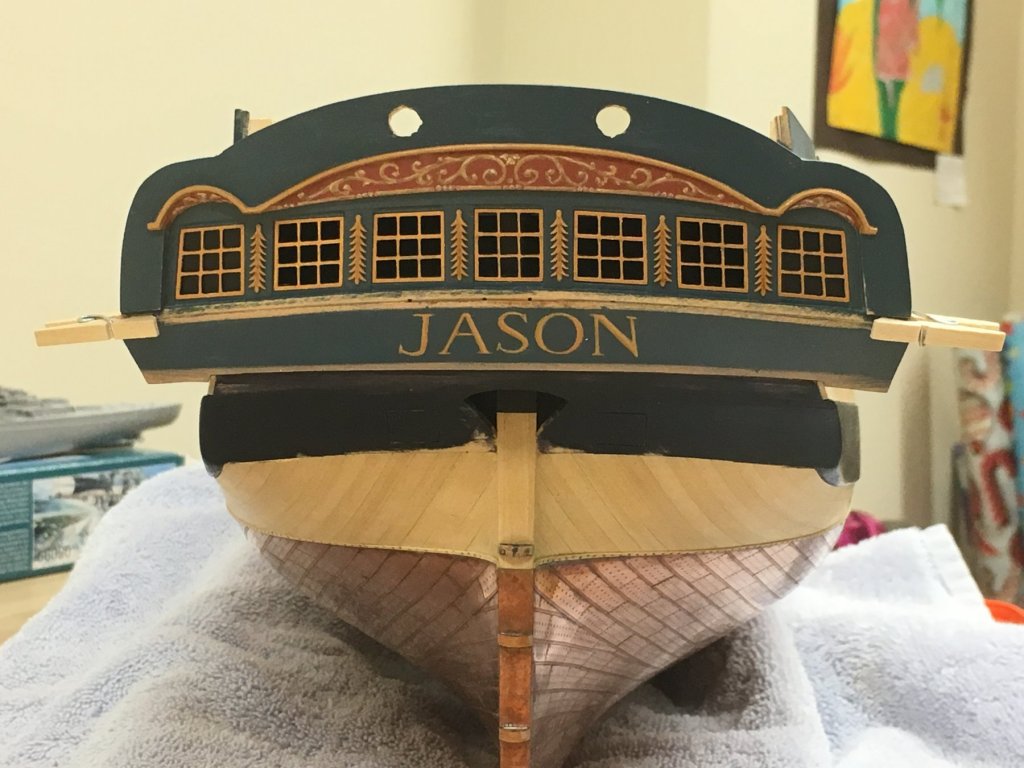
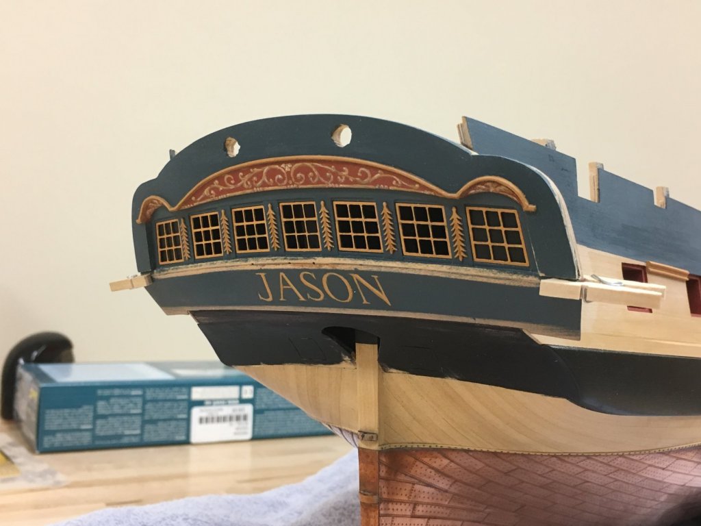
 So here's where I landed with the lettering. First the letters were painted in a darker brown and then overpainted with yellow ochre and few highlights. The goal here was not perfection as I new that was not going to remotely close, hopefully "impressionistic" describes it. Was very happy with the outcome, may touchup a little more but I'm forcing myself to stay away for now. The placement may look a little odd, but I had to estimate where the decorative rails will be so it should be correctly aligned when those are in place...something to potentially still go awry. I'm following the guidance that the letters should fill the upper counter leaving a little space between the rails. The photos are a little unkind and to my eye looks better in person. First picture is the obvious comparison to the kit supplied PE letters, and you can see the perspective narrowing of the font. I placed the lights in the stern while fine tuning the angle as it seemed that these need be complimentary somehow, although the angle varies from every viewing angle.
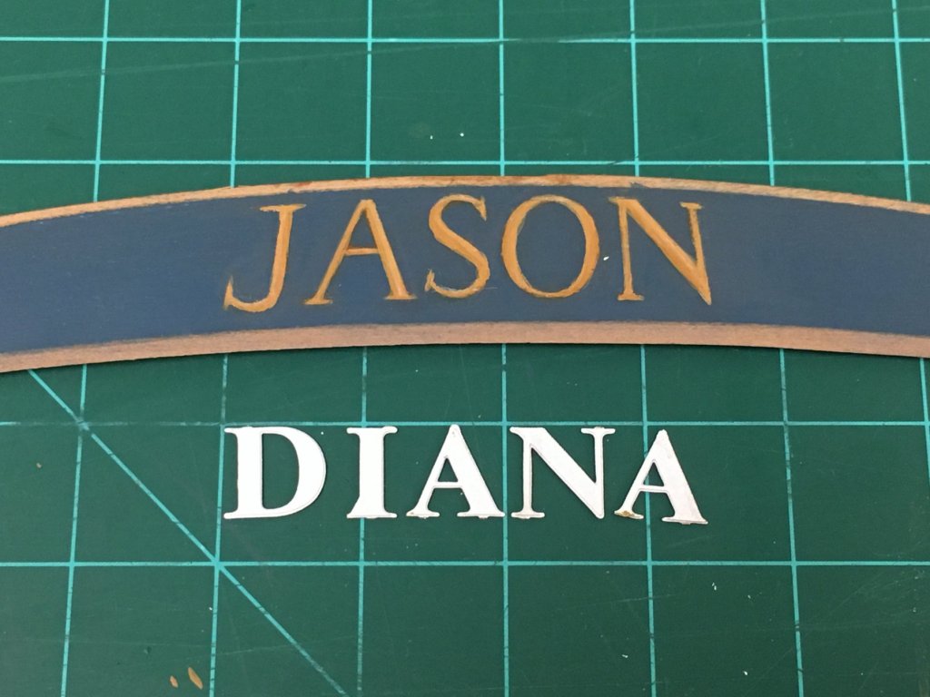
-
I think this is all perhaps a little misleading, and I cannot comment of the Fore and Aft volume. Peterssen's 'Rigging period ship models' clearly states as its premise the documentation and illustration of the rigging found on a contemporary model Melampus, and that alone - with no allusion to represent alternative rigging options or other ships or the models accuracy to reality. Faults present in that model will clearly be reflected in the book, and as such it never purports to be an authoritative source or provide scale illustration. Clarity of illustration, showing the key points and principles is a an important goal, and rigging dimensions are never mentioned or asserted, illustrations in the contemporary bible "Young Sea Officer's Sheet Anchor" by Lever could accused of the same fault and that was truly a professional reference book and not a guide to modelers. Is it really so inaccurate so as to avoid it?
-
Those lights look great, as does the whole planking, good to catch up on your progress Tom
-
Thanks everyone for the encouraging comments. @Carl - I looked at Baskerville, before you posted this I decided to follow Perpetua Titling as a guide as it is probably the closest to whats seen on Victory that I could find, Baskerville looks good as well. There is one problem with all these fonts, and that is the "J", in nearly all of these older fonts the J drops below the level of the other letters (it is invariably the only one to do that) which I don't think is how it would be done. I've decided to us the 'Castella' font as a guide for the J, as the other letters are similar stylistically but a little thicker. However, there is a big caveat here, given that I'm choosing to paint the letters so despite lofty ideas I still need to execute that somehow, and I doubt my skills are up to this level of accuracy or refinement and I'm keeping my expectations at an appropriate level. I think it would be a good game afterwards to play 'guess' the font because I know it will not be as pure as the printed examples.
-
Looking great Christian, love the crowsfeet!
-
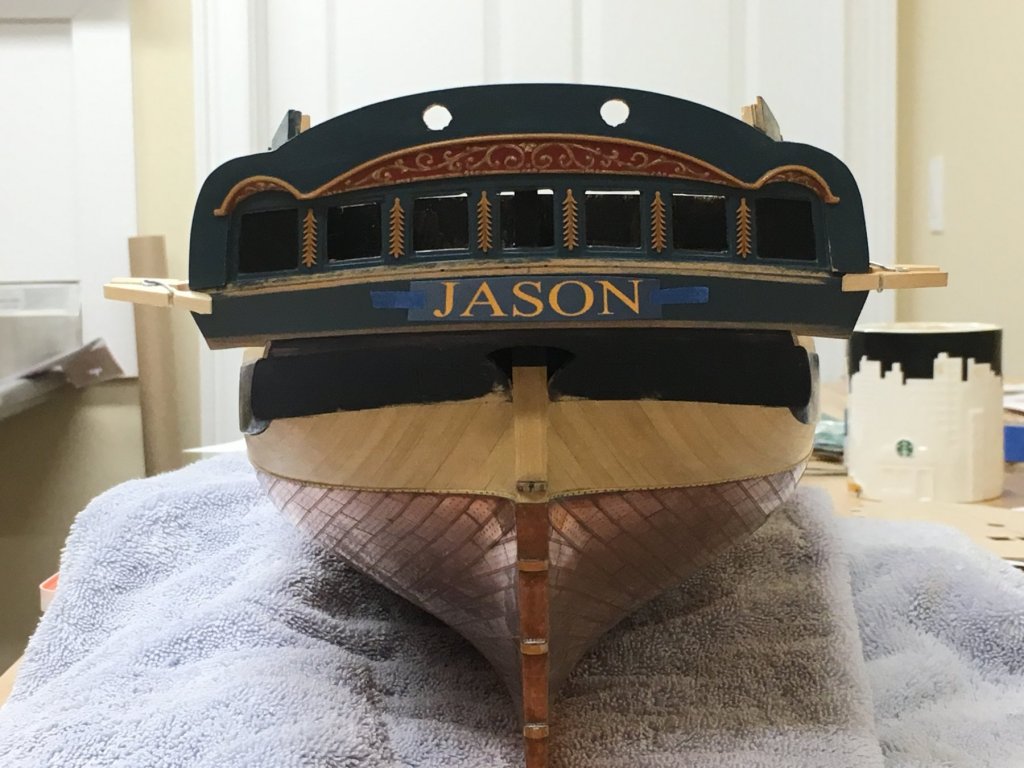
@ Carl - indeed I did Carl, thanks for the good wishes @ Sailor - Thanks for stopping by. I'm not going to go with a nameplate, simply ochre letters painted on the upper counter (what you see is simply some masking tape holding on some paper to get a sense for scale and proportions). The question of font is interesting, I think Times New Roman was invented sometime in the 1930s, but it seems a reasonable approximation for a serif font available in Microsoft products looking similar to fonts used in 1790s (looking at among other things the "Culloden" ship name on the MSW background). Of course, if my attempt at painting comes anything close to this I'll be happy.
-
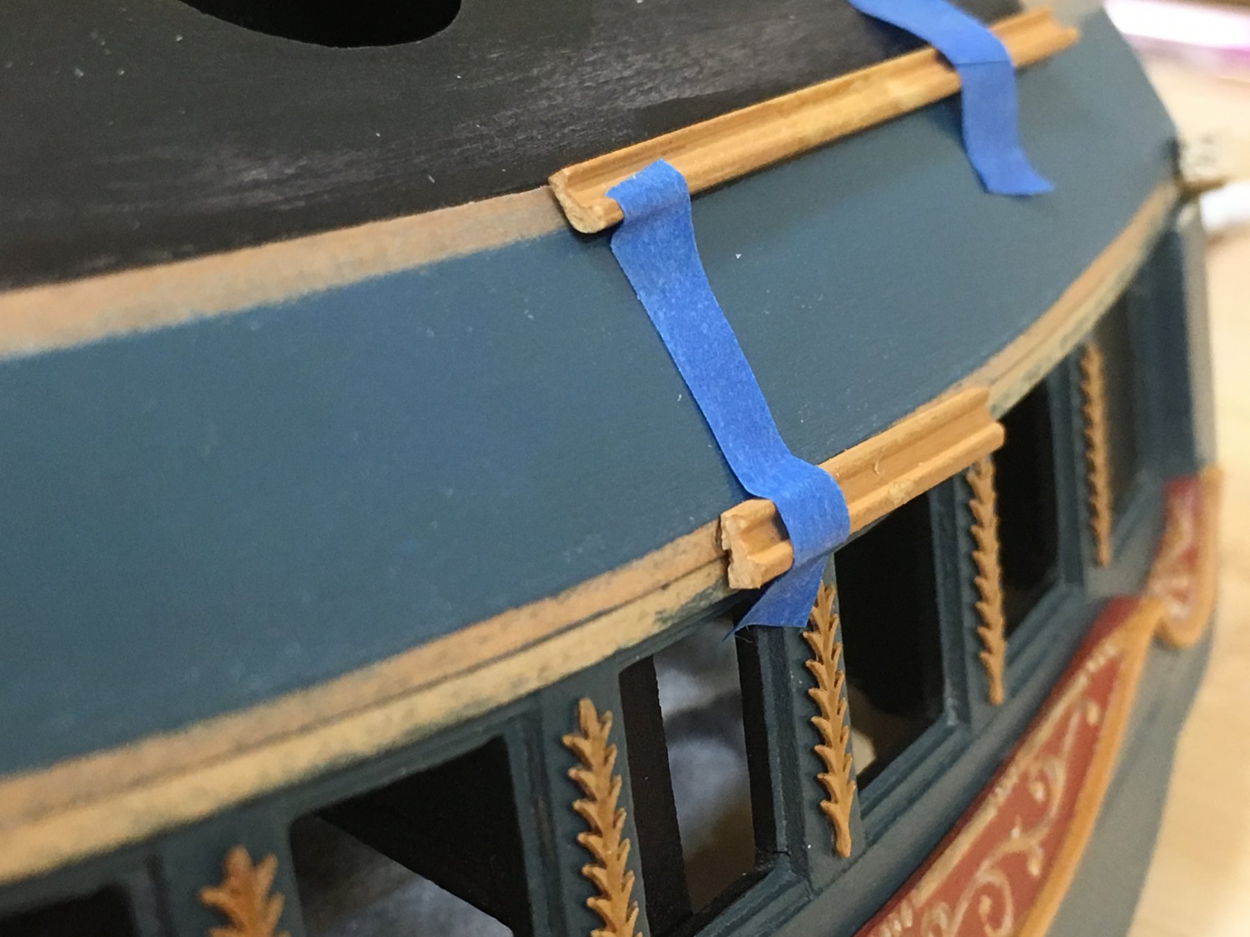
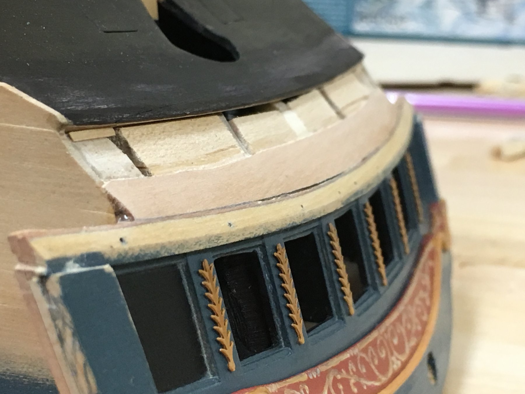
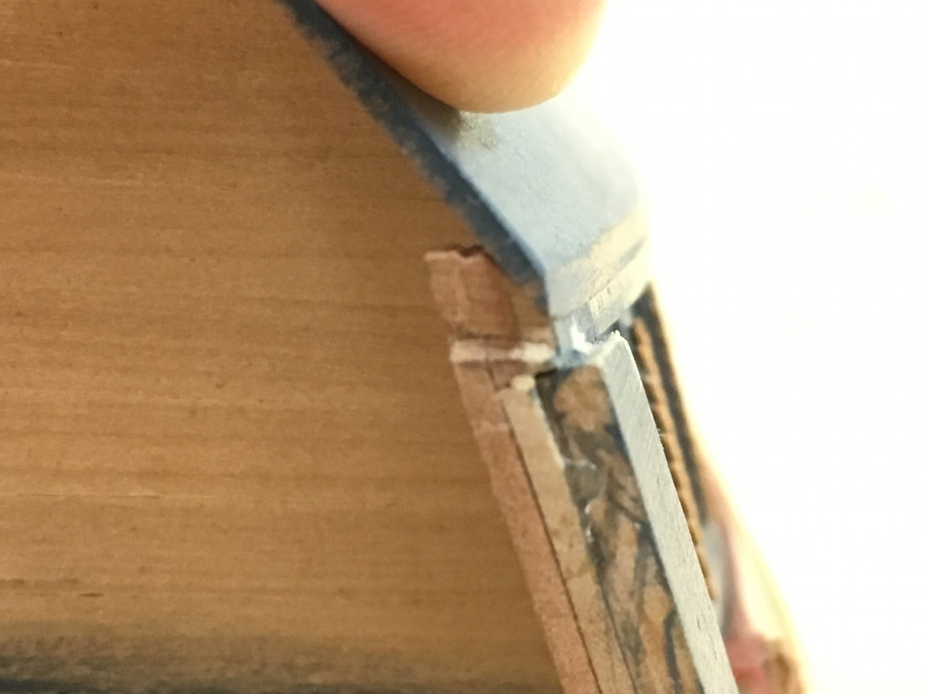
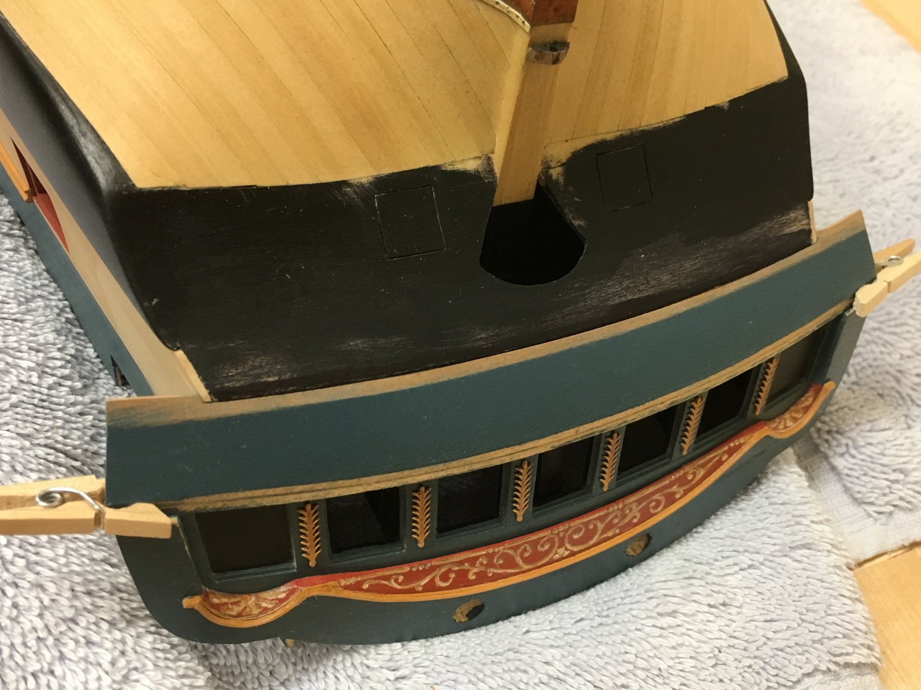
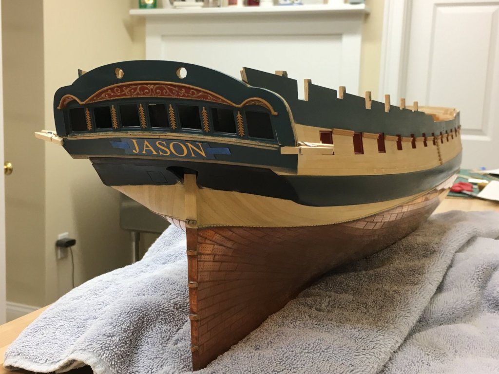
Thomas, Bob, Eamonn, Pat and Mark (nice to have you back!) - thanks for the comments guys and the likes, I very much appreciate your interest. The upper counter and the proof of the pudding... Finally plucked up the courage to attach the stern fascia, really have done about as much on this as I can before fitting, and any final adjustments should be done in place to get a proper feel for the various lines and angles and how this will fit with the side galleries (esp. out edge and gunports). Epoxy was used for maximum strength, so it better be right. It all went pretty painlessly as the placement had already been determined. Then comes the upper counter...this should simply fit between the edge of the upper counter and the stern fascia. I have been planning to use a single piece of 1mm pear for this (I think the kit instructions indicate for this to be planked) and I didn't relax for the whole weekend while I worked on this part. Philosophically, it is what it is at this point as I had done everything I could think of to ensure this fitted well. After making a template for the upper counter and leaving material to allow for fine tuning, the lower edge of the stern fascia (where the upper counter rail will go), was chamfered back to receive the upper counter and ensure the correct angle to the vertical along its length. The edge of the upper counter was then gradually chamfered to meet this angle. I found using a razor blade scraper a very effective way to do this as it kept a nice flat profile and allow the angle with the stern fascia to be followed easily. I had painted the upper counter prior to this process to give a better feel for the shape during this process. (The lower edge was simply masked so the lower counter rail can be glued more easily as I prefer to use PVA glue). The profile at the end shows how this fitted together. Only one potential problem remained. The face with the join needs to be the same width as the upper counter rail (3mm) which required many, small adjustments. See photo below for how the various rails will be positioned. This is not glued yet, but the overall I was very happy with the way this turned out, and 2 small pegs are all that's needed to keep it in position. Before this is attached I need to figure out how to apply the name, at this point I'm leaning toward painting this. I've been playing with some templates made in Powerpoint to just get a sense for size and alignment. This is Time New Roman, 50pt font with y-rotation of 340% and 100% perspective adjustment. I now feel I have proper ship under construction. As always, suggestions welcome!


-
Great work there BE. That gap looks awfully narrow to squeeze two planks into but it's very hard to tell with all the curves and the 2D photos. I'm sure you have it in hand, the planks really seem to distort the visual perception of the hull shape.
- 156 replies
-
- 1
-

-
- pinnace
- model shipways
- (and 1 more)
-
HMCSS Victoria 1855 by BANYAN - 1:72
Beef Wellington replied to BANYAN's topic in - Build logs for subjects built 1851 - 1900
What a great build Pat, she has lovely lines and the research is very interesting. Great to see you overcoming all the challenges.- 1,018 replies
-
- 3
-
-
- gun dispatch vessel
- victoria
- (and 2 more)
-
Jim, I think you've got this sorted and good input from others. Just for completeness though, Petersson also shows the double systems for the fore and main yard so there really is no conflict. As Rick points out, whether double and single comes down to yard size and basic engineering.
-
Royal Navy Ensigns 1750-1825
Beef Wellington replied to michaelpsutton2's topic in Masting, rigging and sails
I believe (but of course can't find a reference) that the red ensign would have been flown by any ships operating directly under Admiralty orders. That would not be typical, as most ships would be under the command of a flag officer even if they are operating "independently" from the main body of a fleet, and hence adopt the red, white or blue squadron designation of the commanding admiral. -
Help reading plan
Beef Wellington replied to Rick01's topic in Building, Framing, Planking and plating a ships hull and deck
Based on my reading of the plan pictures, the hawse hole sits quite squarely above the upper deck, sitting between the upper and lower cheeks. Looking at the first posted side profile where the cheeks would be (even though they are not shown) these does seem to reconcile to be being above (just) the upper deck level. The hole in the deck seems to then be logically placed to allow the hawse to be fed below after the windlass. The second side profile shows the cheeks and upper or hair bracket lower than I would have expected (the upper cheek is located where I would have thought the lower cheek would be) - that looks odd to me and seems to cause the discrepancy, but of course I am certainly not an expert. -
Hi Thomas, somehow I've missed your Syren build up to this point, wow, just wonderfully inspirational work.
-
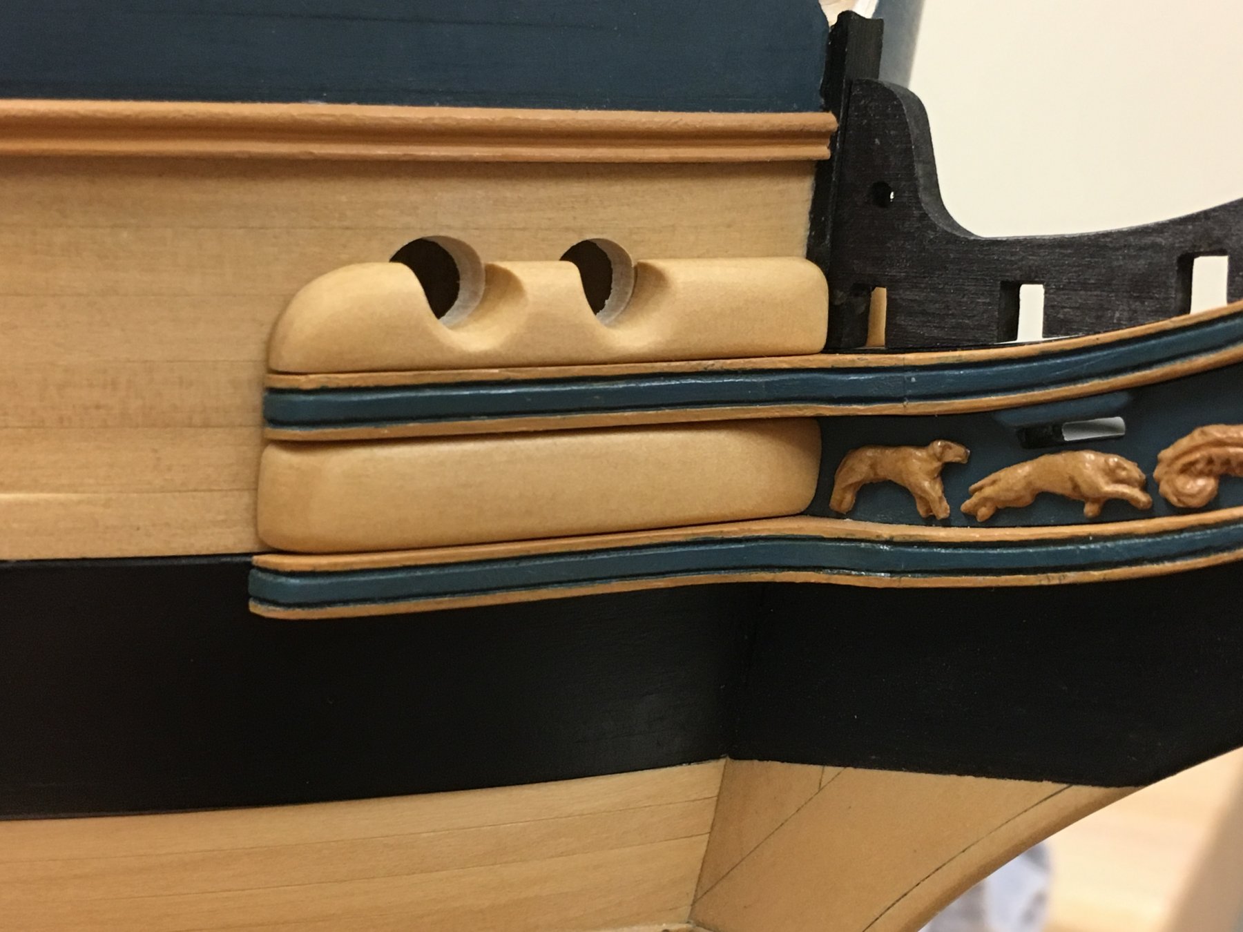
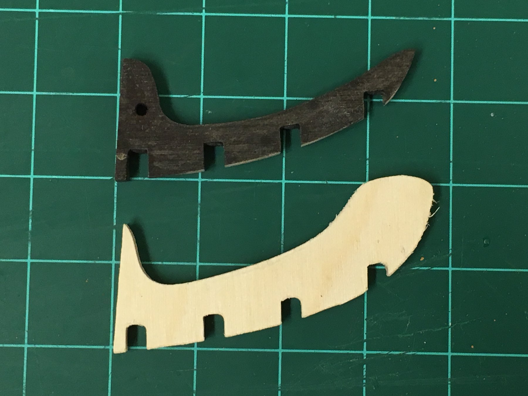
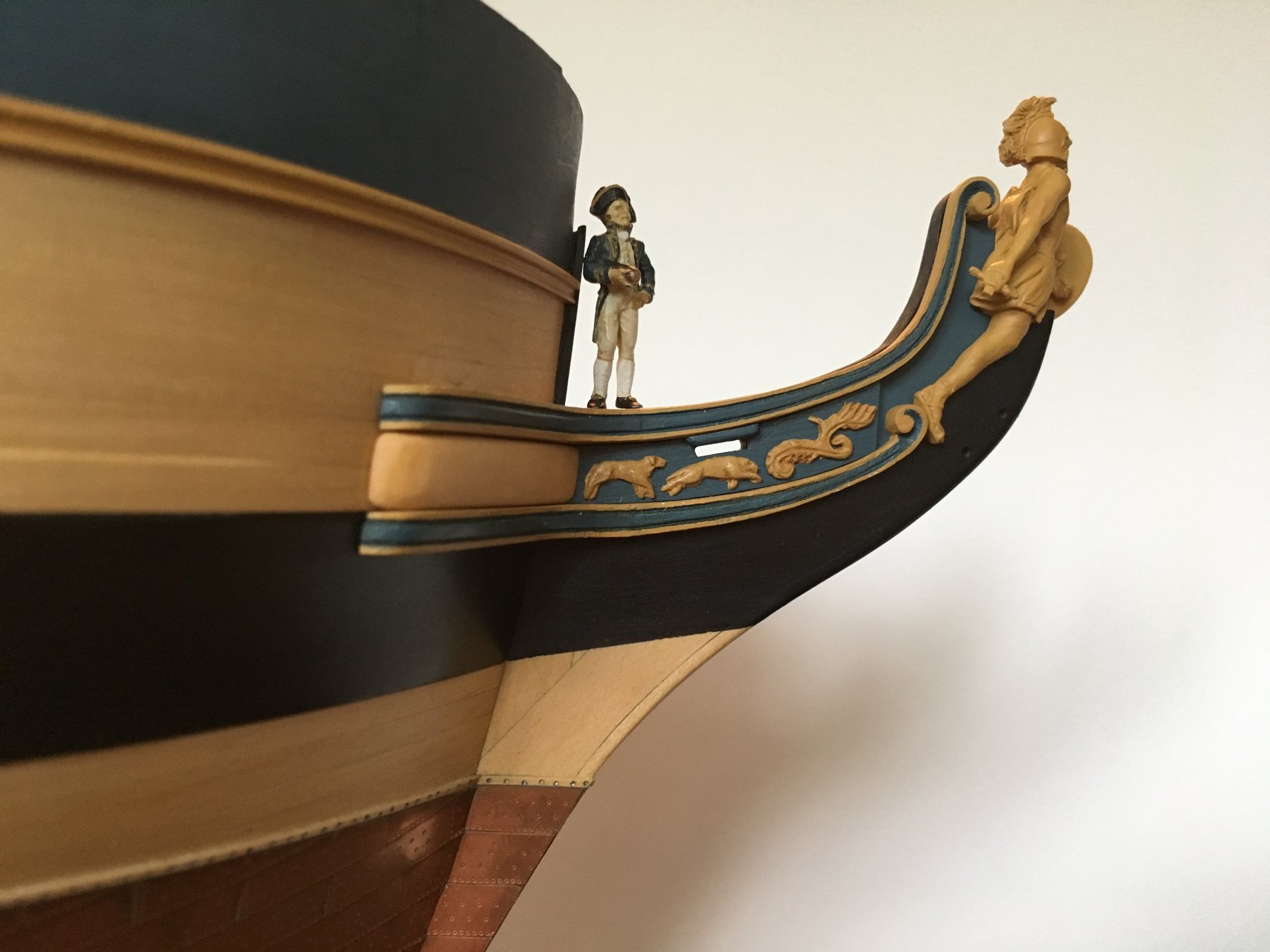
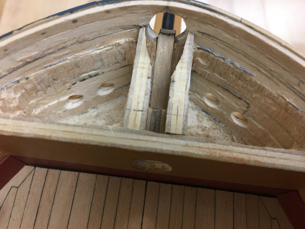
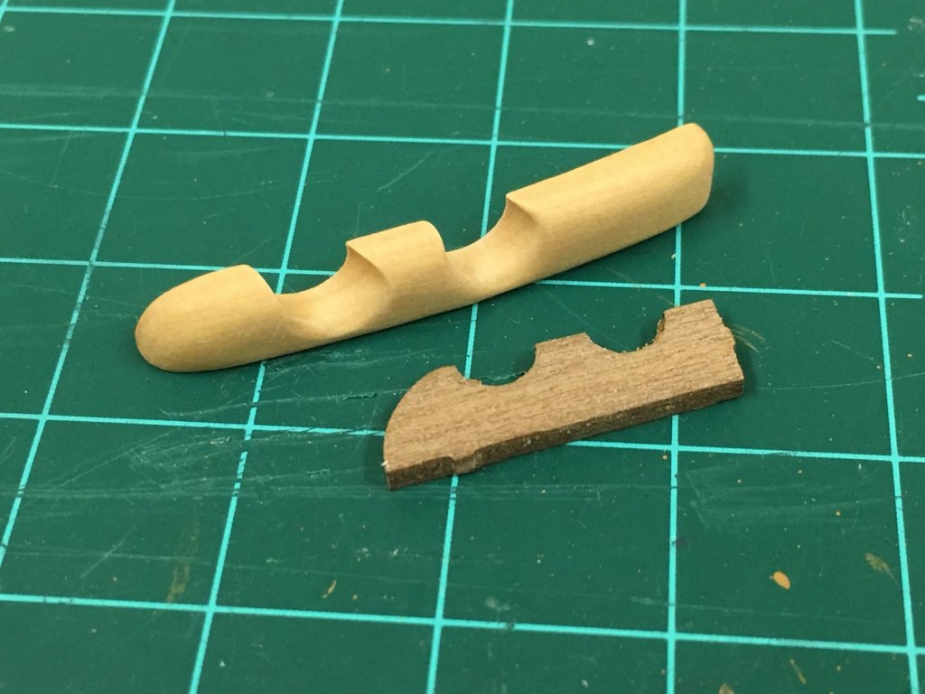
Carl, Rob, Christian, Niles and the likes - thanks for your kind words, encouragement and patience on this slow voyage... Jesse, Dave - Of course you are right, but no matter how many times I tell myself that it doesn't help...I probably have one of those personality disorders along the lines of "well he did it, so why can't I?" And yes, its gets me into trouble with those fixes around the house that I maybe shouldn't be tackling.. Anyway a little update as I really can do no more to the bow at this point, which means I need to get back to the stern...then I remembered that that was basically the reason for me taking a break and starting work on the bow...There are a couple of questions at the end. Once the cheeks and the rails were done, I needed to tackle hawse holes and the bolsters. These had me really thinking, but first step was once again to shape from some thick stock, only this time I had to take it even slower as pretty much the entire interior face needed to fit tightly against the hull because any errors would be really obvious once the holes were cut. The balsa filler blocks were also removed (Interestingly, you can see the outline of the recess that I had put in a long while ago to try to introduce a void behind the expected hole placement to look a little more authentic...seemed a good idea at the time but they would have been in slightly the wrong place) The holes themselves are ~6mm in diameter, and taking a drill bit of that size was clearly out of the question. The hole centers were estimated and I drilled with a 2mm bit in a hand drill. This was large enough to get a round microfile in to gradually enlarge and then use a larger round file. Once the holes were approx. 4-5mm and still quite rough, some tapered dowel was used with sandpaper around to again gradually enlarge until they were approximately the right size. All the time doing this, the bolsters were held in place with fingers so everything would align - I didn't want to commit to gluing in place just yet. Once again, I knew I'd be making my own out of castello, but continuing the trend I think the kit supplied parts are way undersized. One other item to take care of is the Gamming knee, the kit supplied part was generally oversized, but it was necessary to cut a new piece because the back of the knee was undersized. Not sure how much of this will be visible, but it fun to make. The hole is for the mainstay collar, some alteration will likely be needed on the head timbers but that is for another day. This is not attached yet. And the final results...these pieces seem to really bring out the face of the ship and to my eye really add some character. Some questions: The bulwark are considerably thinner than they would be in scale, and although the photo makes it more obvious, this is apparent if you look for it. Also, I know that the hawse holes were lined in lead, but I'm not seeing this as a feature standing out to me looking at models, in many it seems these were just painted ochre...would welcome other's thoughts and suggestions here. I'm leaning toward a 'lead like' grey just on the inside of the bulwark but not extending over the bolster. For fellow Diana kit builders. I placed the waste rail on the starboard bow side only as it seems to me that this could cause problems with the fitment of the bow grating against the hull - anyone have any experiences on this?

-
I keep coming back to admire the pictures and trying to get my head around those incredibly thick wales! I can only imagine how much time it took you to shape and fit these rather than a more typical planking process. Would be great to see how you did those when you get caught up, At the bow, I'm guessing you cut each from thicker sheets based on the hull profile? - just can't imagine how you could bend that thickness! Pictures look better each time I look.
- 346 replies
-
- 3
-
-
- terror
- polar exploration
- (and 2 more)
-
Treenails of course come down to personal opinion, but my opinion is I like your opinion 🙂 I hope one day to be able to admire your completed Terror in person!
- 346 replies
-
- 8
-
-
- terror
- polar exploration
- (and 2 more)
-
Nils, missed a lot of your recent progress but it is so great to see everything come together. Your KWdG really has a presence would look fantastic in any setting. I hope your admiral could be persuaded to let it in the house
- 2,625 replies
-
- 5
-
-
- kaiser wilhelm der grosse
- passenger steamer
- (and 1 more)
-
Hi Mike, really nice progress on the bulwarks, you've captured the shape very nicely. Looking forward to seeing the rest of the yellowheart and ebony go on.
-
I'm 'away' for a few months and I find you've started another model - the moss most certainly does not grow on you Sjors! (if the expression translates!) Looks like you're off to a great start despite the keel setback, should be beautiful when completed. How does she compare sizewise to the Aggy? - bigger ship but a smaller scale? I did not see the popcorn machine on the way in, is it gone already?
-
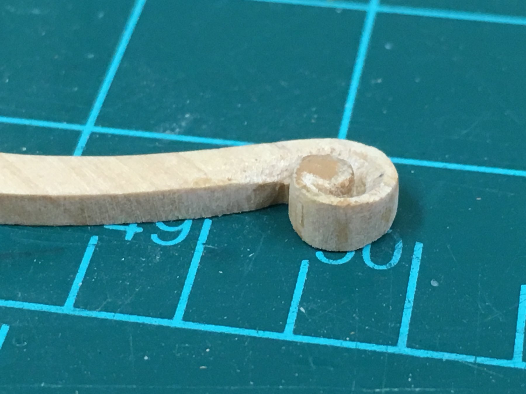
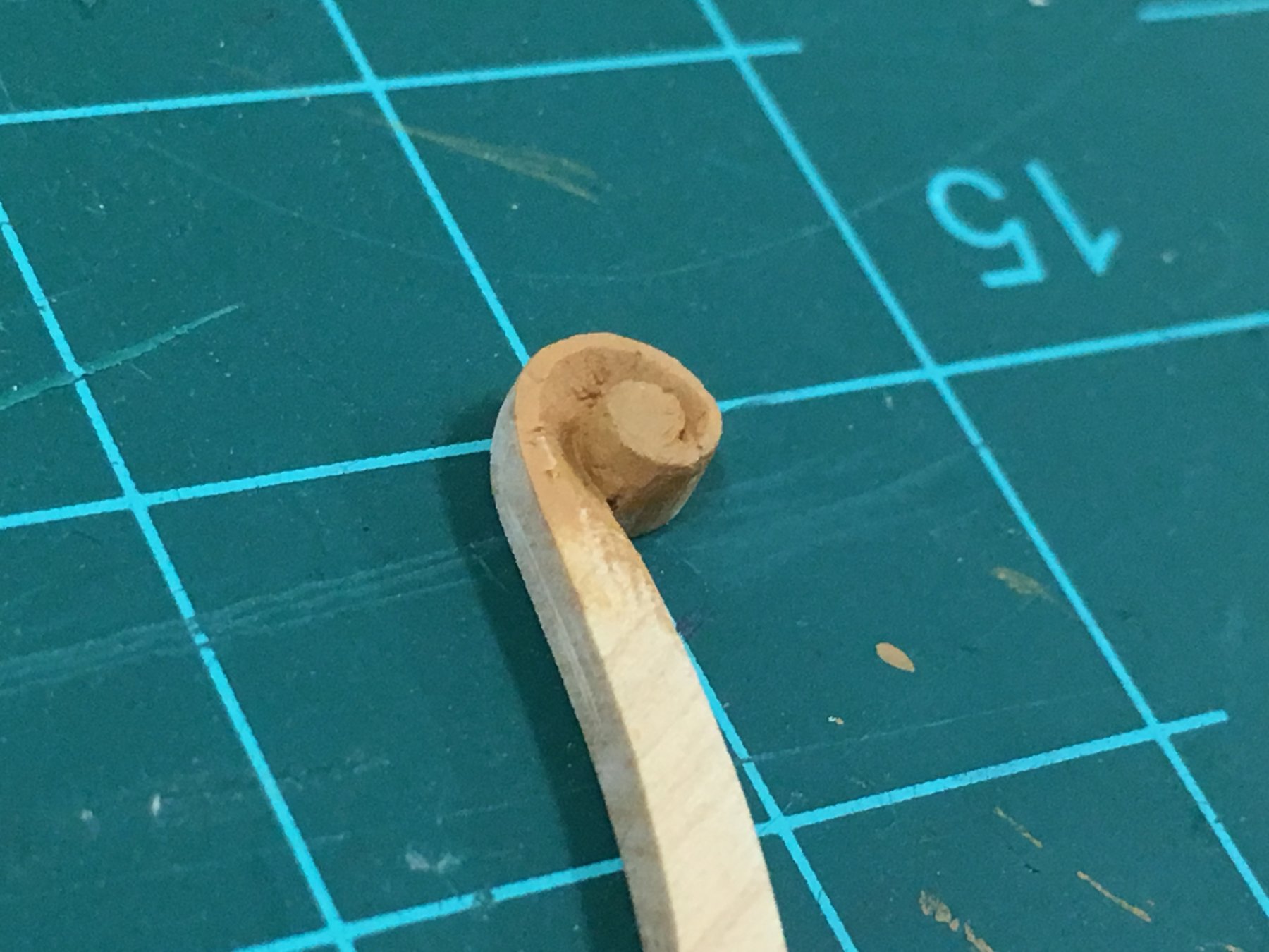
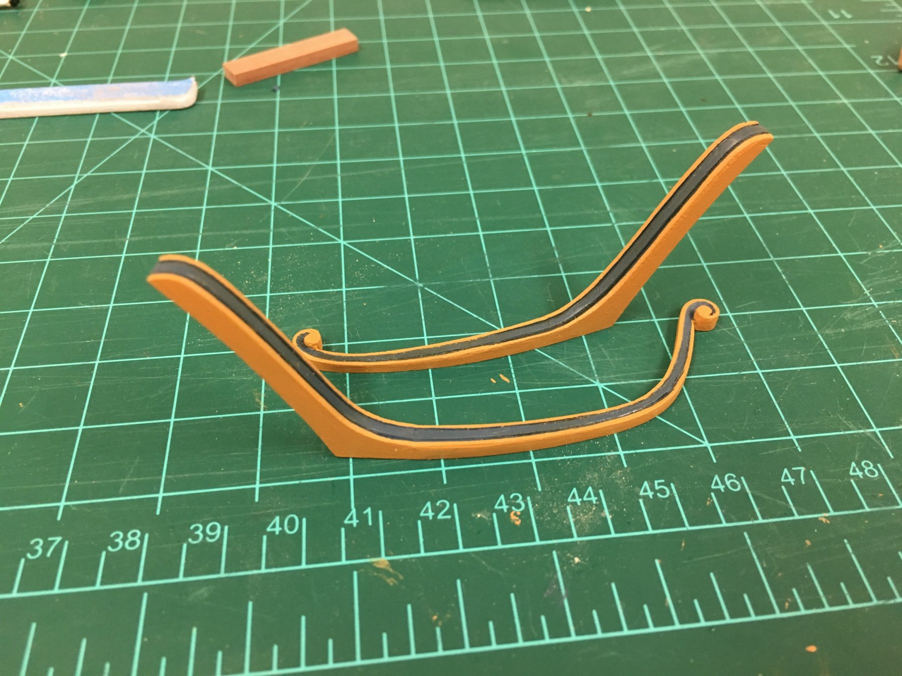
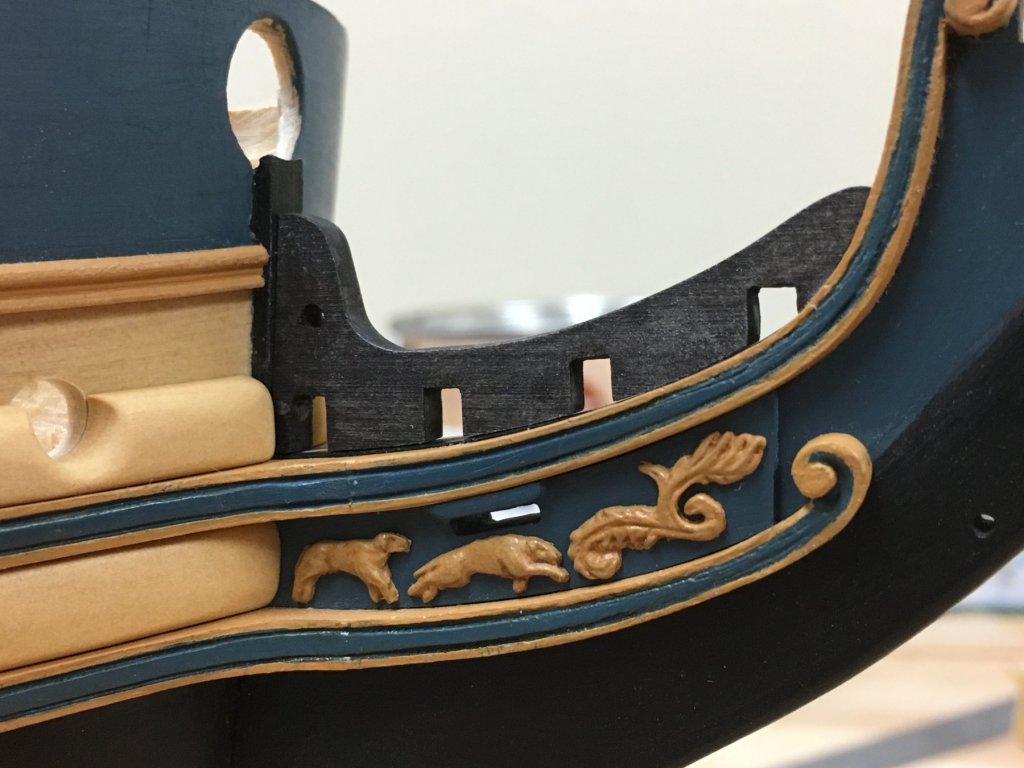
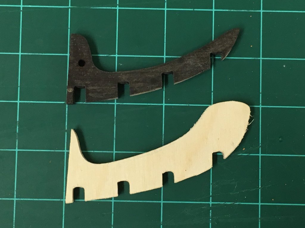
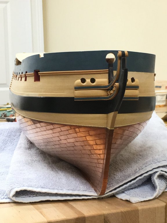
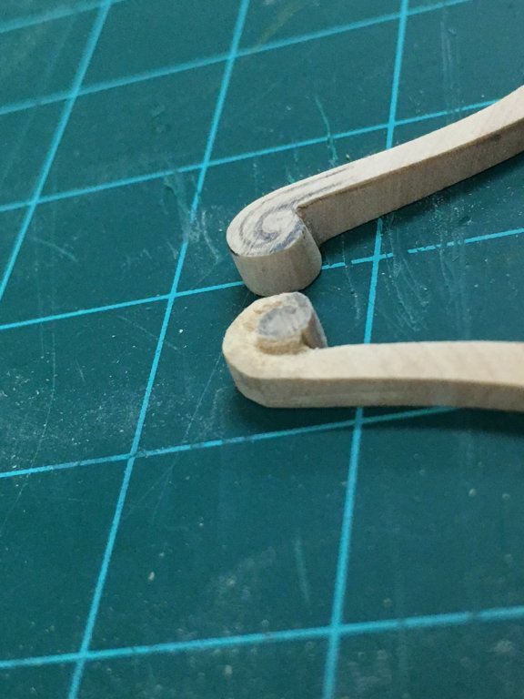
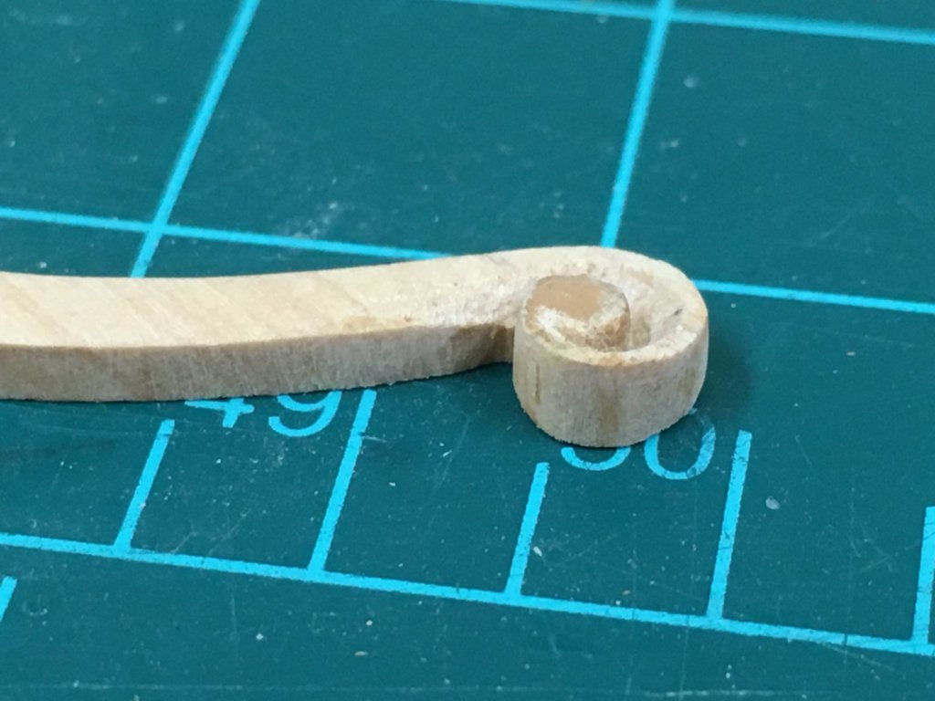
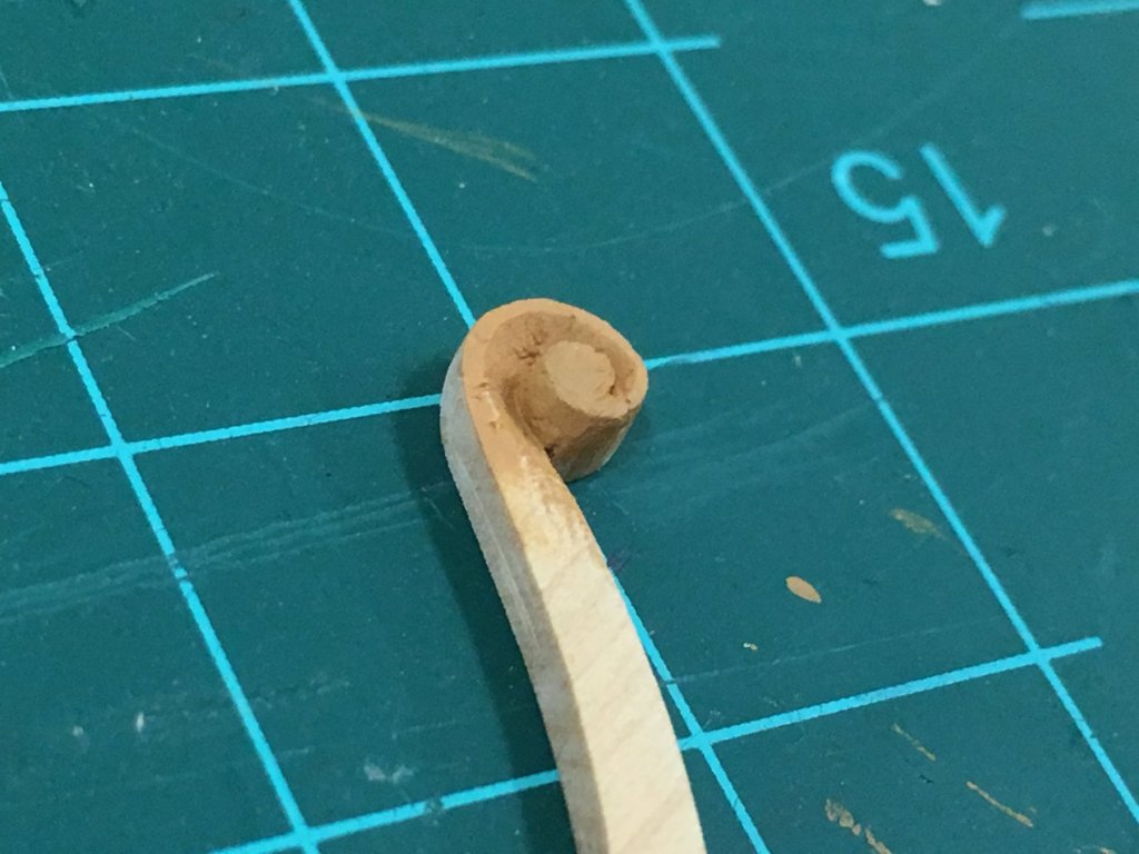
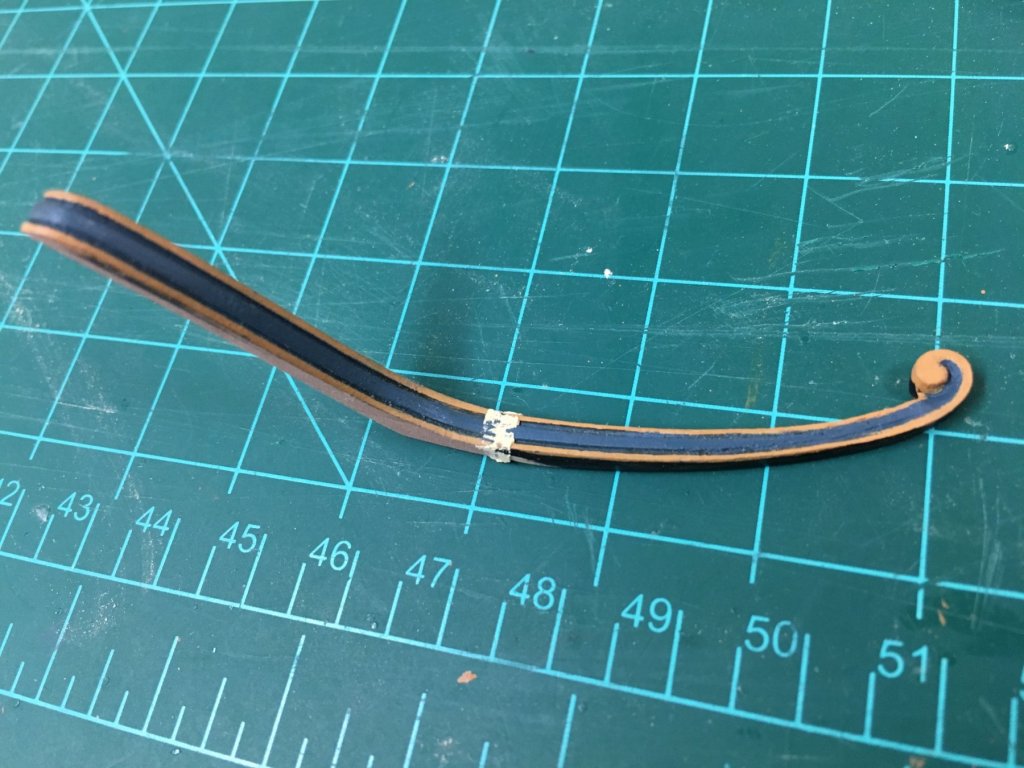
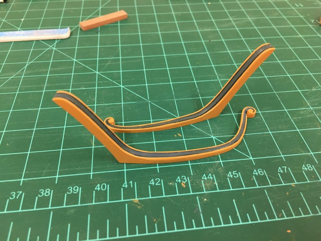
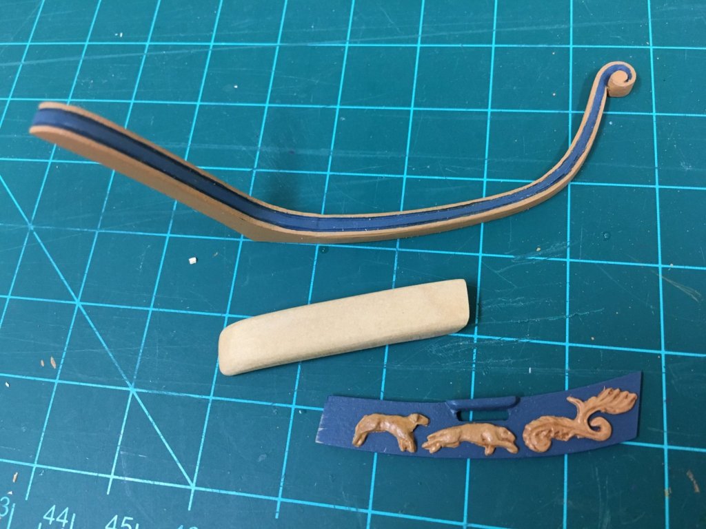
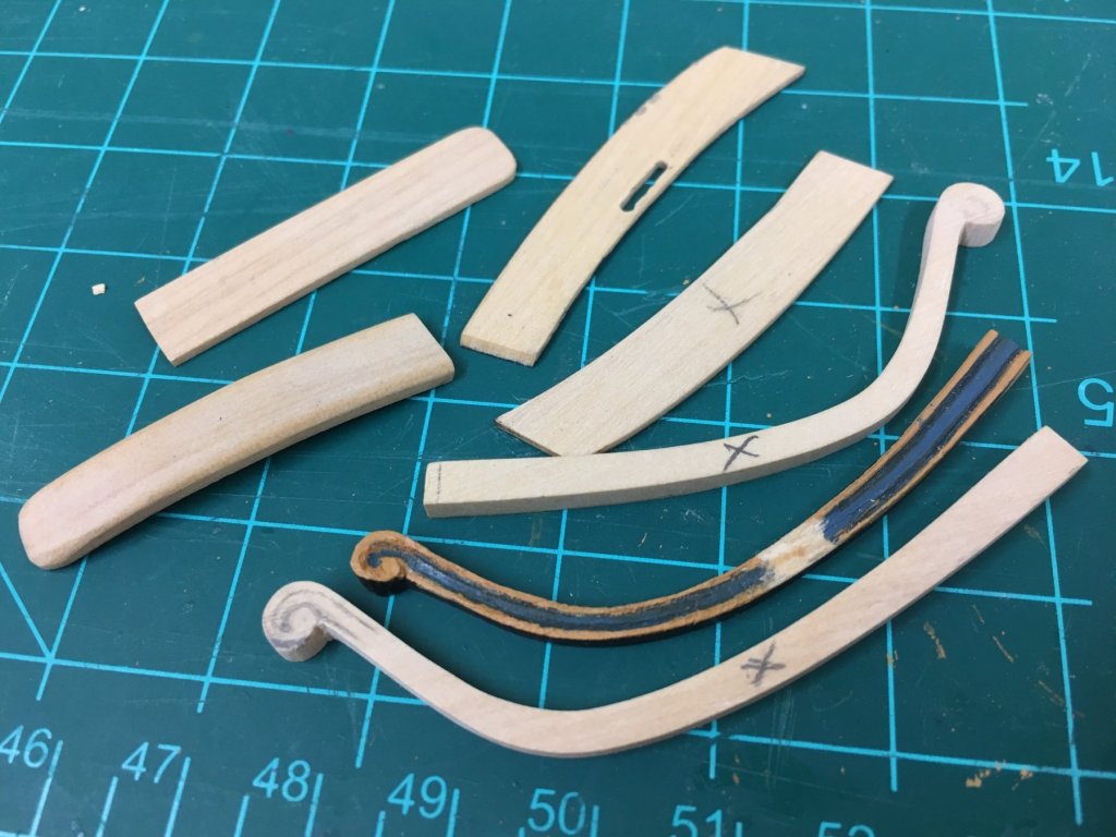
Hi Chaps, we'll I am back after a little hiatus. Ron, Mark, Pat, Bob and the likes - thanks for the kind words as always. Sjors - Its nice to have the option to use the kit part rather than nothing, its insurance I've landed a new job, which is some relief - even though I had time on my hands I couldn't enjoy building but did what I could when the mood took me. I'm not sure how the scratch builders feel, but these cheeks and rails had me thinking I'd never get them done and asking myself if I'd bitten off more than I could chew. First off, I had to decide how I wanted to terminate the rails. This period seems to be a bit of a mix in styles, mixing more elaborate decoration with a hint of future frugality. I decided to err on the side of ornamentation after studying some NMM models, which basically just meant a larger scroll on the hair bracket and lower cheek I tried to follow guidance in TFFM as much as I could, and I've shown the progress pics below. This wasn't as hard as I thought and for a first effort I was pretty happy, but I'll leave final judgement to others. I knew I'd be painting these, so I found myself occasionally putting a think coat of paint on to get a better sense for the contours which is difficult with the pale castello. Once the scrolls were done, I made a scraper for the contour and tried to add the profile. I found this very tricky and found myself battling the curve, the changes in width and the slight grain, especially in the thinner sections. First approach was to shape the cheek piece and the rail and then glue together (I did these off the model painting would be next to impossible once mounted). This didn't work as well as hoped, the profiles didn't match and the edges had rounded, but some filler and rework did the job. For the others, I glued the cheek piece and the bracket before profiling which seemed to work fine. I used a touch of sepia wash to highlight the profile. Near the scroll, there is barely a profile so paint is needed to give the effect. Overall, I give myself a "C" on the profiling: hopefully could do better next time but needed to move on or forever be stuck in hairbracket purgatory. Next time () I think I'd try using pear rather than castello but didn't have any of the right dimension to hand to try. Lastly, couldn't resist adding a little more detail than the kit offers and wanted to add both a Filling piece and Trailboard. Looking at contemporary Artois models, the filling piece is quite substantial and adds a distinctive look. First off, I tried making a 1mm thick version bent to the hull shape - too thin. I next tried a 2mm think version, but again felt it was too thin. Tried 3mm, but it was impossible to bend, so went with a 5mm castello sheet and shaped as needed. This was quite a bit of work as none of the sides are at 90deg, and the hull curvature needs to be accounted for, luckily this doesn't need to be perfect as the interior faces will be hidden by the cheeks. The trailboard was relatively simple but again took a while to get the appropriate shape. Once complete these should go together like a jigsaw puzzle..... And the finished result. These will not be glued until I have the port side pieces finalized, but they fit together just fine. Overall, I found this tricky and time consuming, but educational. Without detailed plans there was a lot to consider to get the alignment looking right to my eye, for example, the lower cheek scroll terminating at the foot of the figurehead, the hair bracket scroll aligning with the rounded top of the lacing piece. Finally, recognition for all those failures forever consigned to the wastebasket of progress....

-
Hi BE, sorry to have missed the start of your new build but nice to see so much progress in one sitting. Looking very sharp and neat as to be expected, lovely work.
- 156 replies
-
- 5
-
-
- pinnace
- model shipways
- (and 1 more)
-
Hi Rob, really nice progress on the planking, love the tapered sternpost - think your solution is a little more elegant Hopefully I'll have an update soon as the bug has bitten me again, you look to be really having some fun with this kit. All the best.
-
Nice fix Christian, looks great. I think I'm going to go and put the seats of ease in, but of course I'm no-where near as far advanced as you.
-
Hi Christian, that looks great. I'm still stumbling through a solution to the upper and lower cheek/head rails and would love your opinions on those when I get comfortable posting. You really did an amazing job with the kit parts to get them looking as good as you did. I've been tearing my hair out with placement and I was interested to see you placed the lower cheek at the top of the wale, that's were I believe it should be to get it looks proportionally correct to my eye - but it seems that on the models and AOTS the placement seems to sit slightly below the top of the wale. I think you've given me the courage to go with that so I appreciate the photos of the completed headworks. Really beautiful work!