HOLIDAY DONATION DRIVE - SUPPORT MSW - DO YOUR PART TO KEEP THIS GREAT FORUM GOING! (89 donations so far out of 49,000 members - C'mon guys!)
×


Beef Wellington
-
Posts
2,249 -
Joined
-
Last visited
Content Type
Profiles
Forums
Gallery
Events
Everything posted by Beef Wellington
-
 Very interesting Vitaly, will follow your progress.
 -
Dziadecek - in which reference did you see that coppering was done from waterline down, and for which time period? Many thanks
-
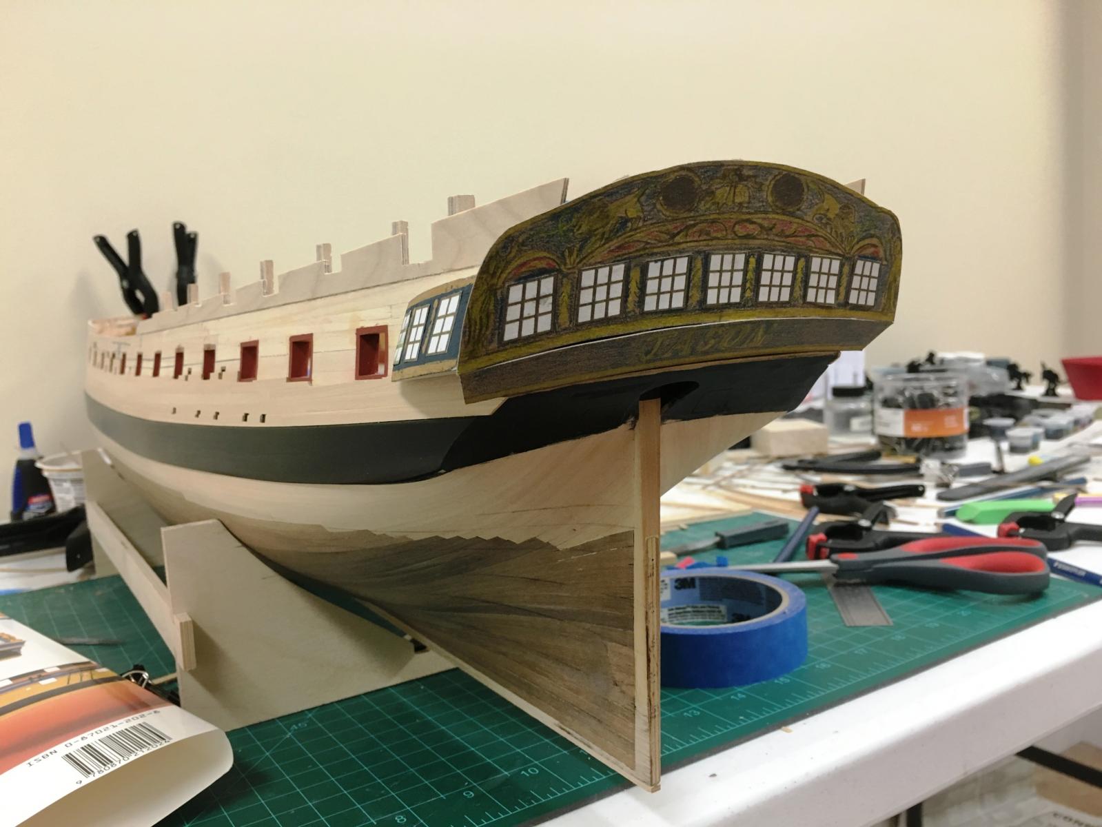
Carl - what you see is my cardboard mock-up/template And no, I don't like the white windows...they're just cutouts from a photocopy of the kit PE to see exactly how they would look.
-
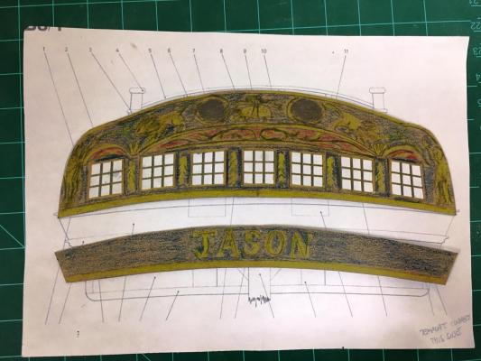
Hi Mike - well...I suspect that that is where this is going , the kit provided castings are definitely OK, but I have been considering doing my own carvings based on 'Jason' mythology - you can see my badly drawn impressionistic golden fleece in the center of the fascia . As it stands, the kit supplied PE is pretty flat, not the '3D' look I'd like to achieve. I'll think more about that once the stern fascia is done, more than enough on my plate right now.
-
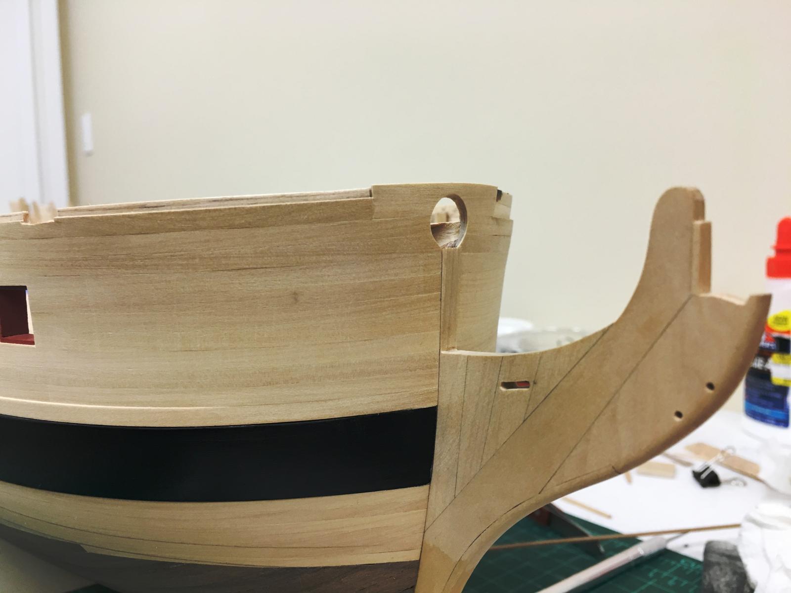
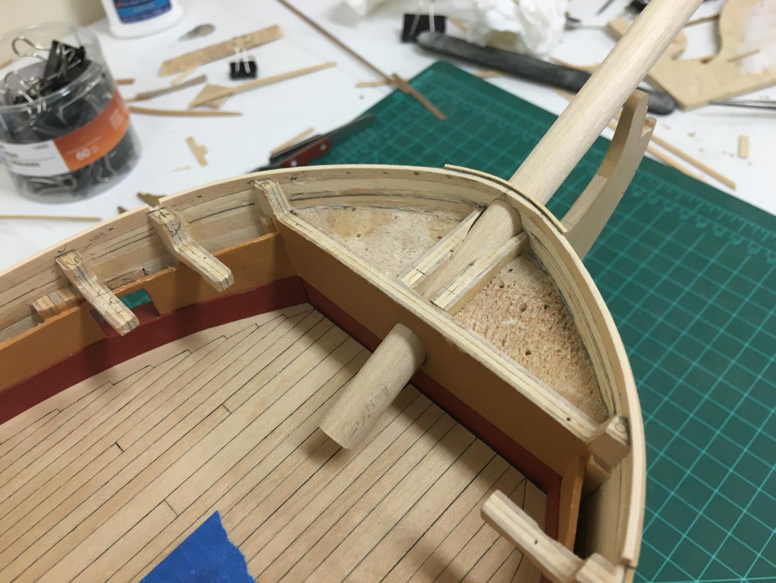
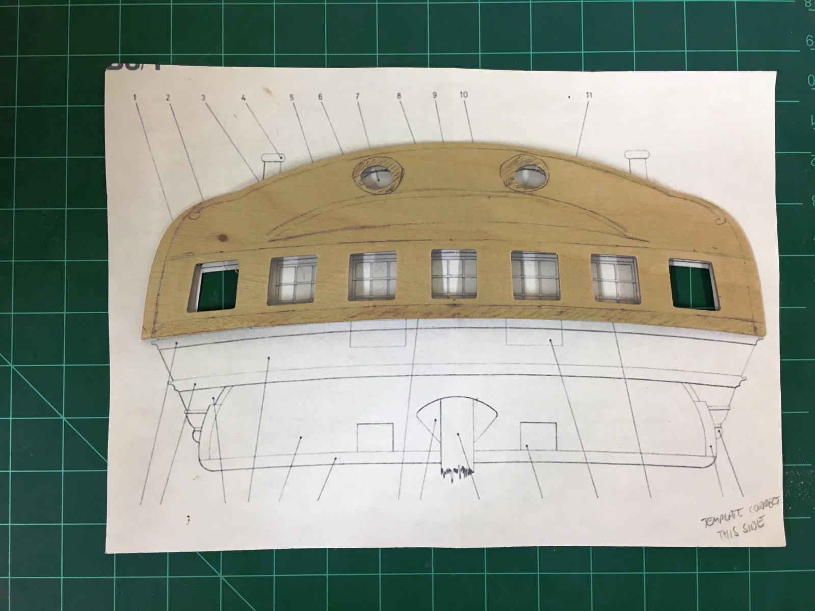
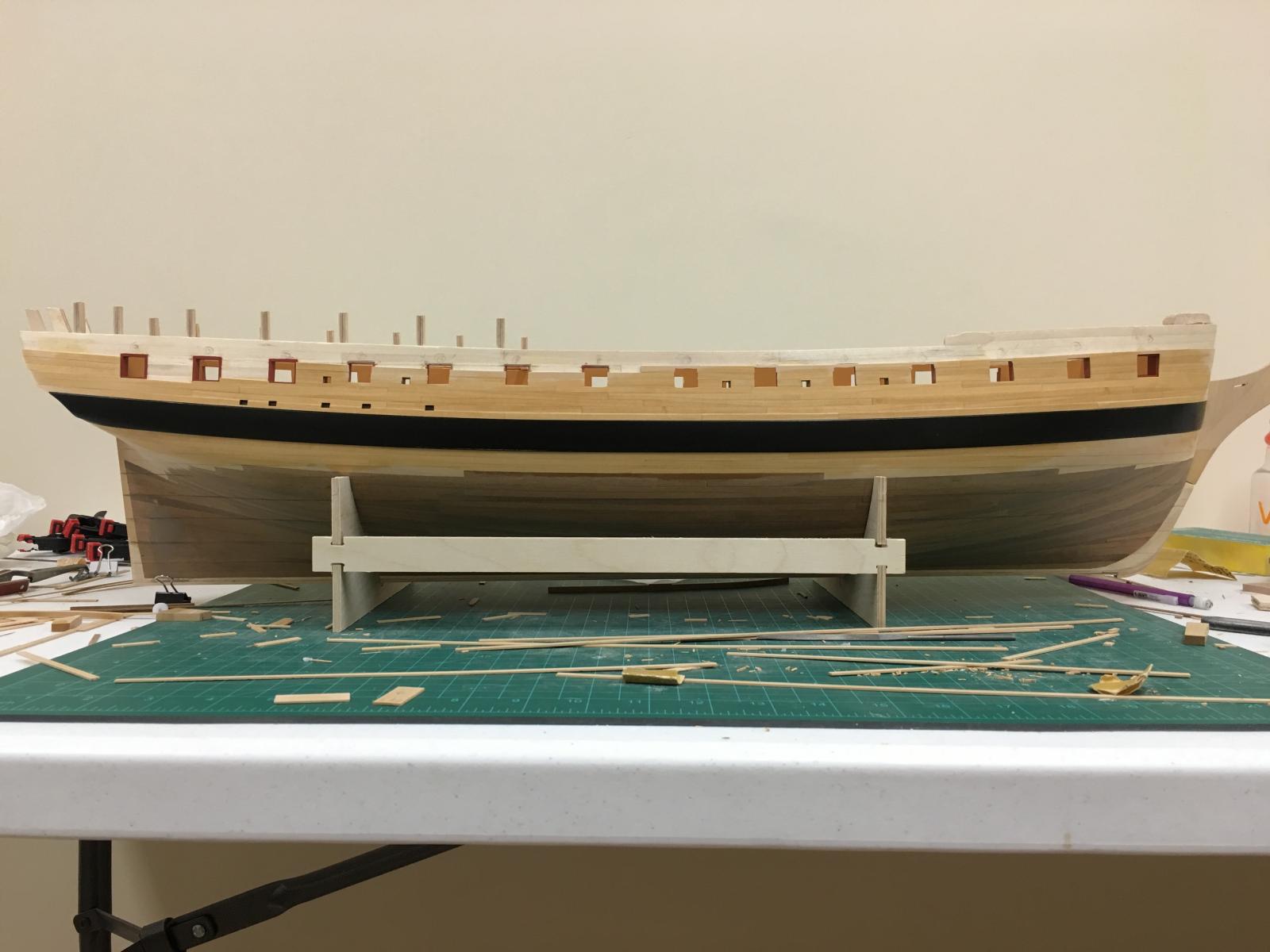
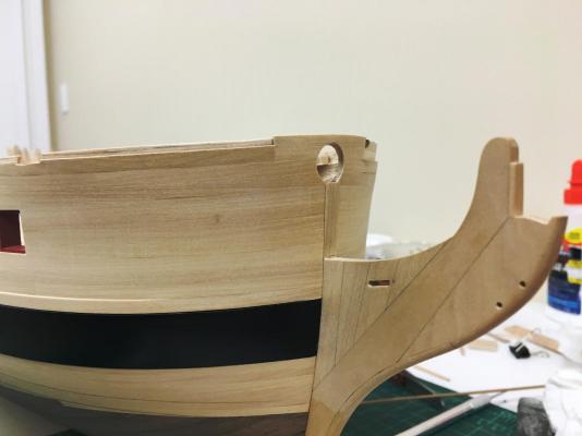
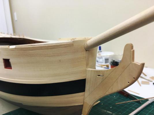
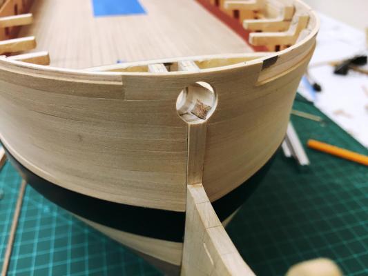
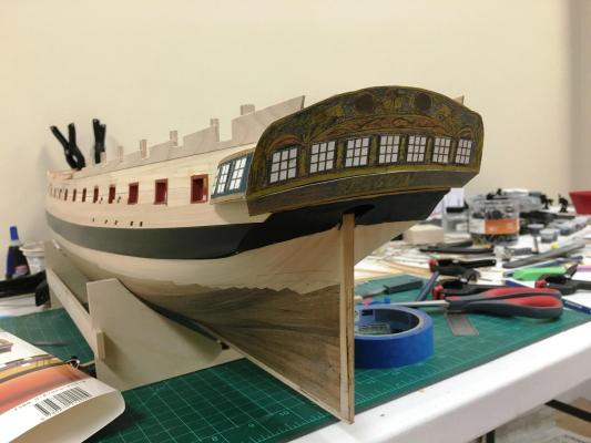
Thanks Pat and likes for the interest. Jesse - hope you're feeling better, your Syren is looking fantastic. BE - glad to see you back in your new work area, jealous how clean and tidy it is Stem and Stern: Planking seems to be never ending with all of the various ports, it seems there isn't one plank that can simply be cut to length and glued in place, but at least I've been managing to get at least a couple done each day. I've been spending quite a bit of time trying to figure out two key elements... The bow is coming together, and thankfully it seems my modifications to replace the cutwater and have a properly fitted bowsprit to haven't ended in disaster. I needed to remove the filler block to allow the bow planking to be clamped in place and this was a delicate time, it strengthens quite nicely with the laminated layers, again I'm using PVA glue. The bowsprit hole has been fine tuned and quite happy with the result. Overall the modification added a lot of extra work, but I'm glad I did it. The uppermost shape of the bow is more rounded which seems more intuitive and consistent with the AOTS diagrams, but differs from the kit which seems to be more 'pointy'. Ray had identified that the bow cap rails in the kit ones are undersized means that these would need to be redone anyway. I still finalizing the exact shape of the bow bulwark following the sheer, but this also seems to consider the angle of the foc's'le deck - will be leaving a little extra here to be cut back later based on what looks right. The stern has had my head in swirls for some time. There has always been something that bothered me with the kit pictures but I couldn't figure out why - the kits stern fascia seems too wide, too 'flat' and the stern lights too small and far apart. After enlarging the diagram in the AOTS book I figured out what was up. It seems that Caldercraft used the stern projection to shape the stern fascia without accounting for the vertical angle and lateral curve. Estimating what this would be I cut out a card template to confirm the needed shape on the lower fascia and the upper counter. This now seems much more in keeping with the needed curves. A problem to deal with down the road at the PE lights, I think these made undersized vertically, again because they do reflect vertical foreshortening. Glueing photocopies of the lights in place has made me wonder whether I'll be happy with these, because in addition the panes do no match the desired curve of the fascia or the vertical alignment of the hypothetical stern timbers....something to ponder some more. Kit supplied fascia compared to AOTS diagram, the lower curves match perfectly even though they shouldn't... Card template compensating for lateral curvature and vertical slope... What these look like in place, much nicer in my opinion.


-
Caldercraft HMS Mars plans and instructions
Beef Wellington replied to sharkscanner's topic in Wood ship model kits
I'm sure Jotika/Caldercraft would be happy to replace them if you were to contact them. -
Terry, check out the planking tutorial here, link in first post, very helpful indeed. http://modelshipworld.com/index.php/topic/439-planking-tutorials/#entry4719
-
Great stuff Jim, any pics you can share?
-
Bulkhead 1 looks to be sitting too high, maybe that's the problem you are describing - suspect the top should be flush with the top edge of the keel former. Are you going to try cutting rabbet for the planking? It does make things easier, and would likely be easy to do before you attach the bow by shaping the edge of the keel former. Good to be underway!
-
Terry - look forward to your build log. I used balsa fillers on my current 'Jason' build, it is easy to work with. Remember that the fillers aren't really there to provide any additional strength but rather to help get a better lie of the planks, especially at the bow/stern to help ensure that there are no flat spots which is tendency without them. I did glue the strips to the balsa just to be sure with PVA without any mishap.
-
Gary, I'm in awe, lovely work doesn't begin to describe it.
-
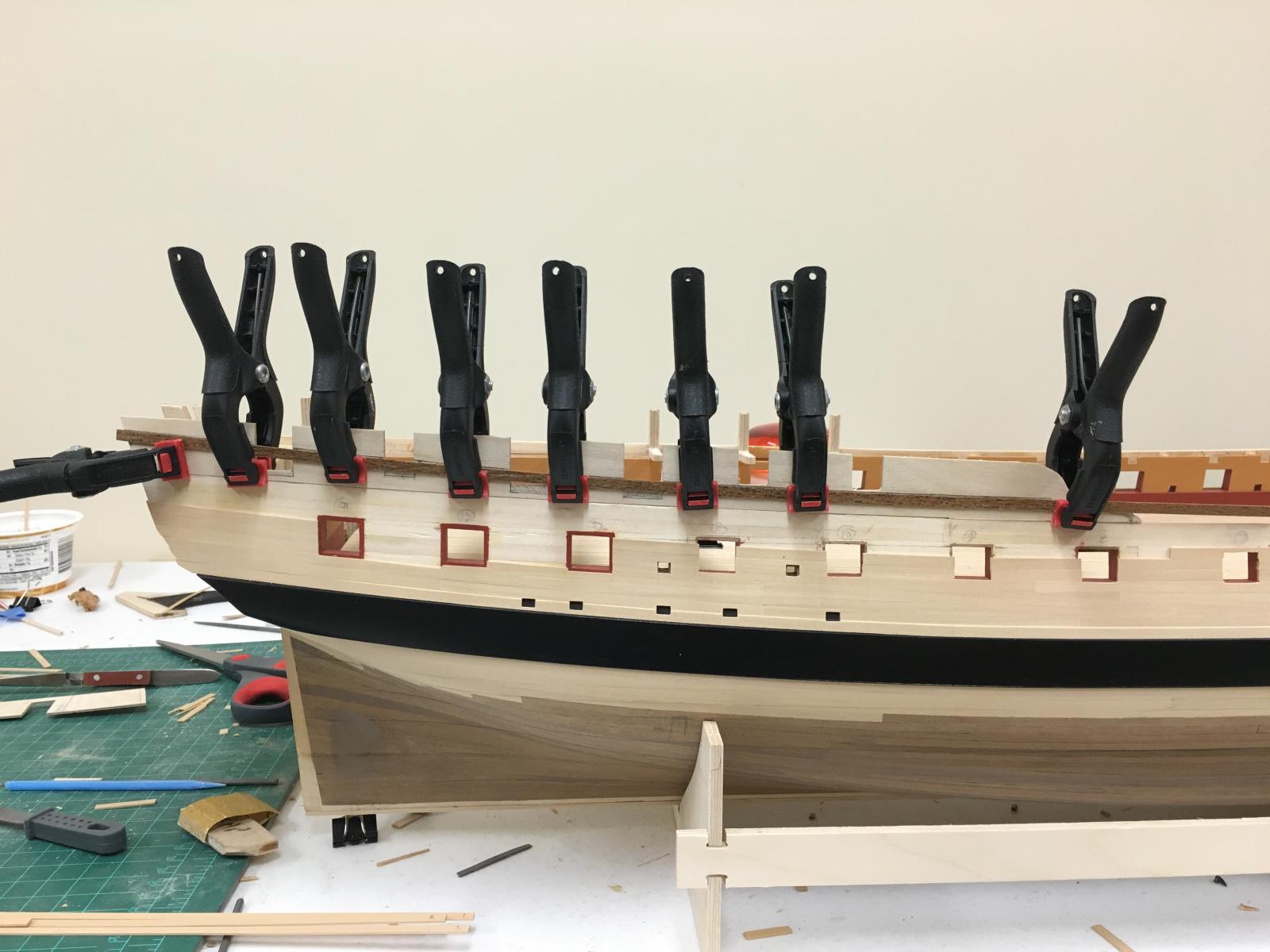
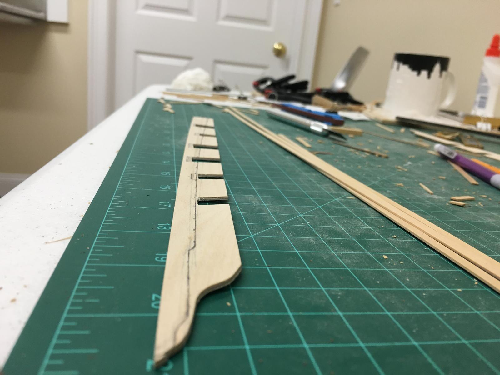
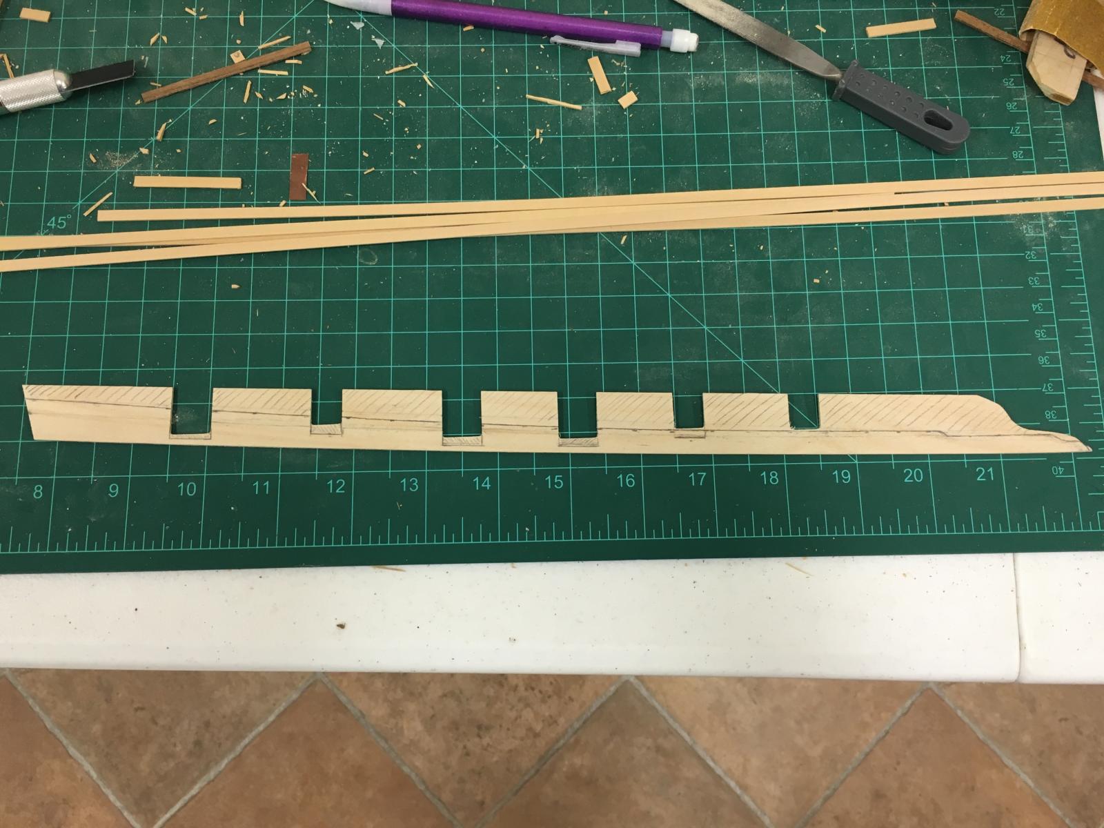
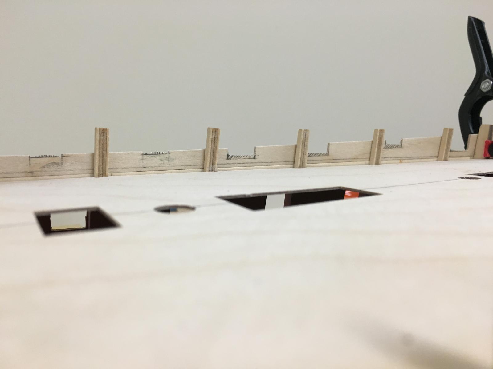
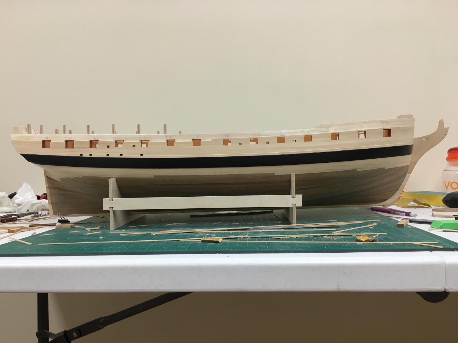
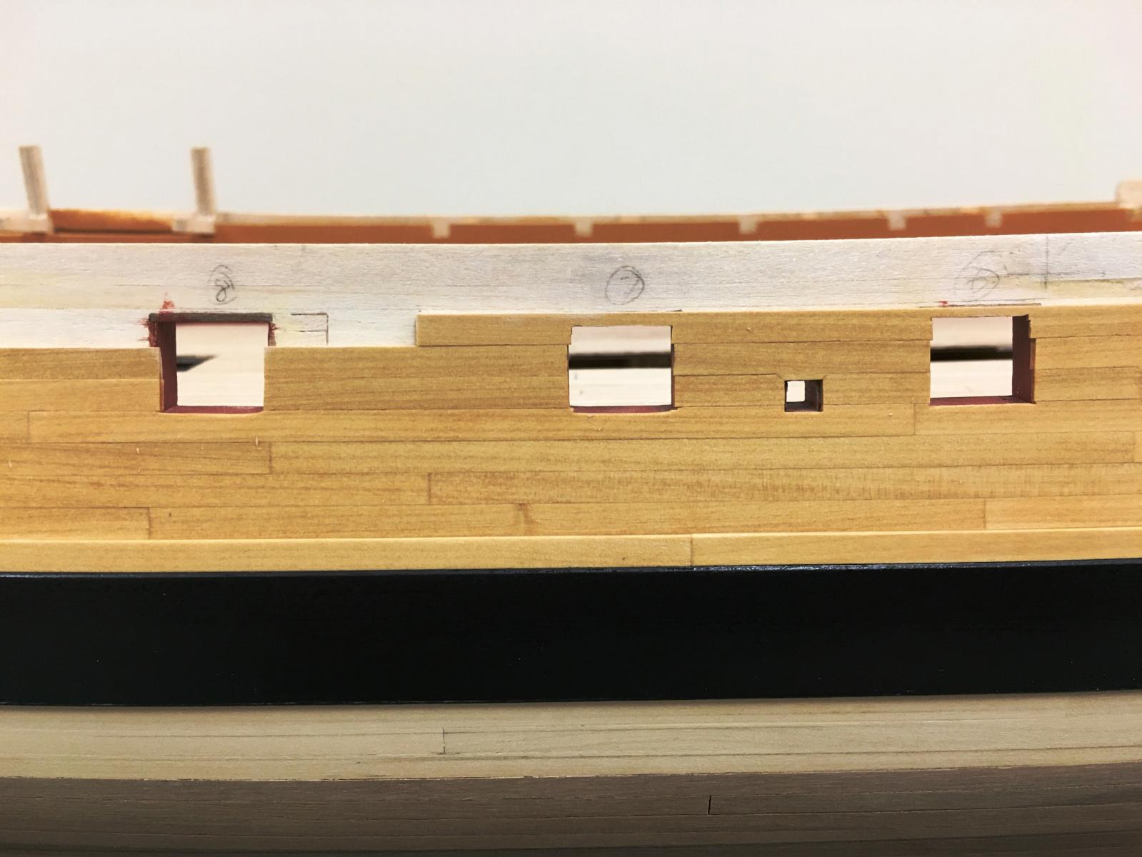
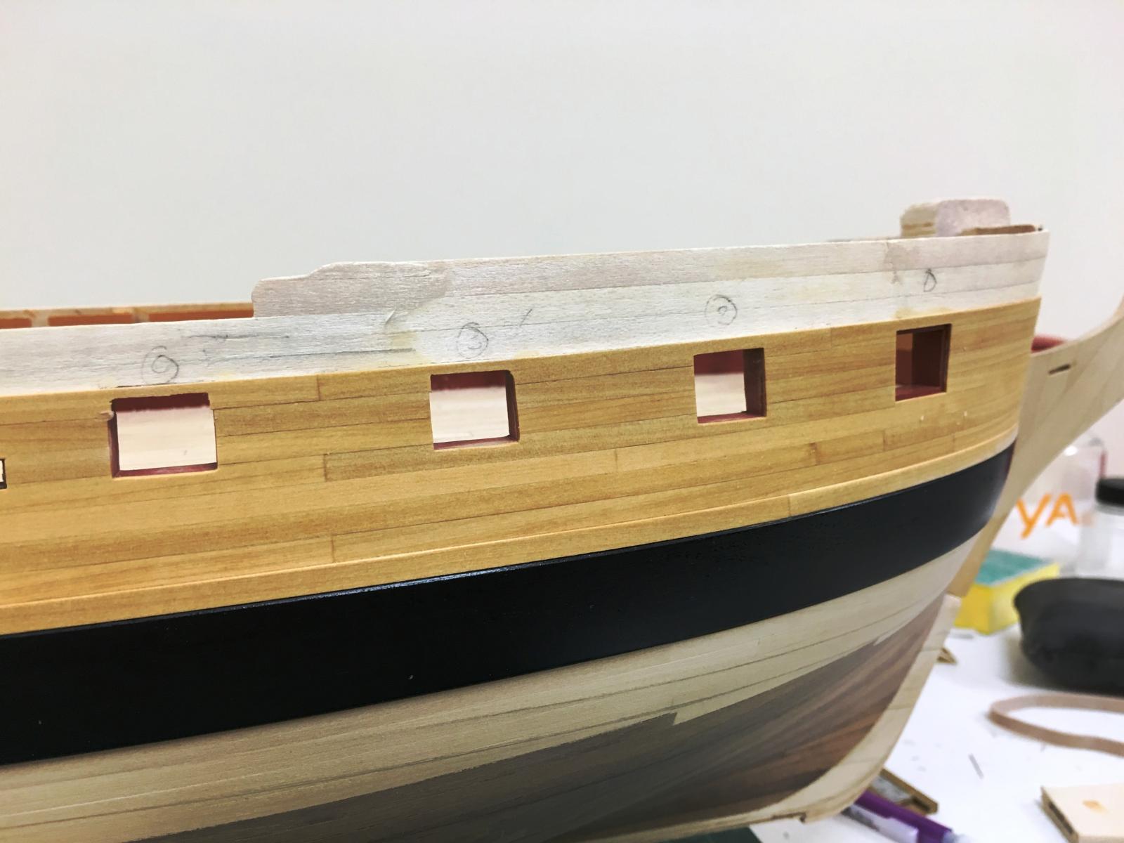
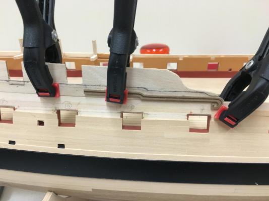
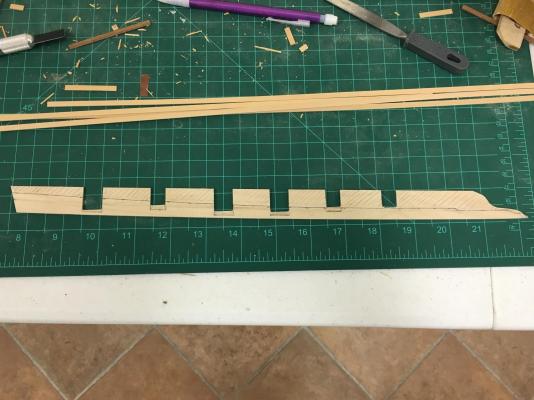
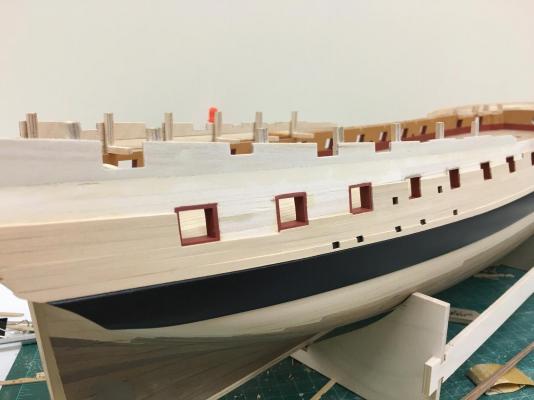
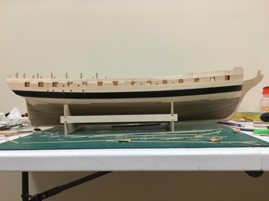
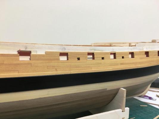
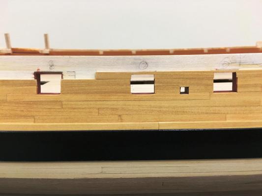
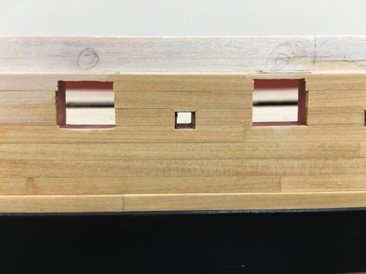
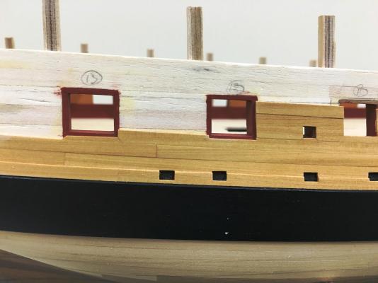
Reached the point where I need to decide what I want to do with the rear bulwarks, built up or open. After reading various sources, it seems that Jason would have been built with the built up barricades at launch which were back in fashion by the time of construction, even though various plans of the Artois class show open bulwarks. I've decided to go with the open bulwarks like many who have built this kit as this more in keeping with the look of the NMM models which I'm going for. Armament seems also to cause a little confusion due to changes at the time, with slightly varying numbers quoted. Seems there is no reason to deviate from what is suggested by the kit, and I'll stick to having a few carronades for visual interest rather than replace with cannons. So what does this mean? I decided to keep the ply bulwarks and reshape them, I'd already planned the other planking around using these so this was no issue. The required shape however had me scratching my head for a while, but then it suddenly dawned on me that the top of the bulwark would simply follow the sheer. To get a nice smooth curve some strip was used to a consistent height from the whale (in this case ~50mm, leaving just a tad for some potential future fine tuning). I estimated the position from various pictures which all seem to vary slightly - this seems good enough The front portion is brings in a few additional challenges, so I cut out the stb main drift to help with shaping The curve of the top of the bulwark is quite apparent...shading beneath the ports is not correct at this point, which needed to be tackled next... Once cut, the next thing was to adjust the port sills as these seemed too high. To do this the deck was fitted and then measured up approximately how far the port sills should be for the cannon and carronade ports followed the line of the deck allowing for the final deck planking. The lateral position was not changed. The shading indicates material to be removed. And finally glued in place....planking can continue.


-
Mike - I just ordered this kit, and you build log will I'm sure be invaluable. You did a really magnificent job, well done, the planking especially came out really well and certainly good to see what is possible. Very nice indeed.
- 109 replies
-
- 4
-

-
- 18th century longboat
- model shipways
- (and 1 more)
-
Tom, just caught up on your log, what a great looking model, well done. Love the look of the sails, really brings it to life. Looking forward to whats coming next...if you can spill the beans.
- 212 replies
-
- 2
-
-
- constellation
- artesania latina
- (and 2 more)
-
Really nice work on the mouse(s) Kevin, serving looks great.
- 1,319 replies
-
- 4
-
-
- caldercraft
- Victory
- (and 1 more)
-
Just found your log Peteri, always good to see a new Snake build, even though you are clearly well into it. Looking good!
-
Dave, good to see a new HMS Snake build, will follow your progress, you look to be off to a solid start.
- 25 replies
-
- 4
-
-
- snake
- caldercraft
- (and 1 more)
-
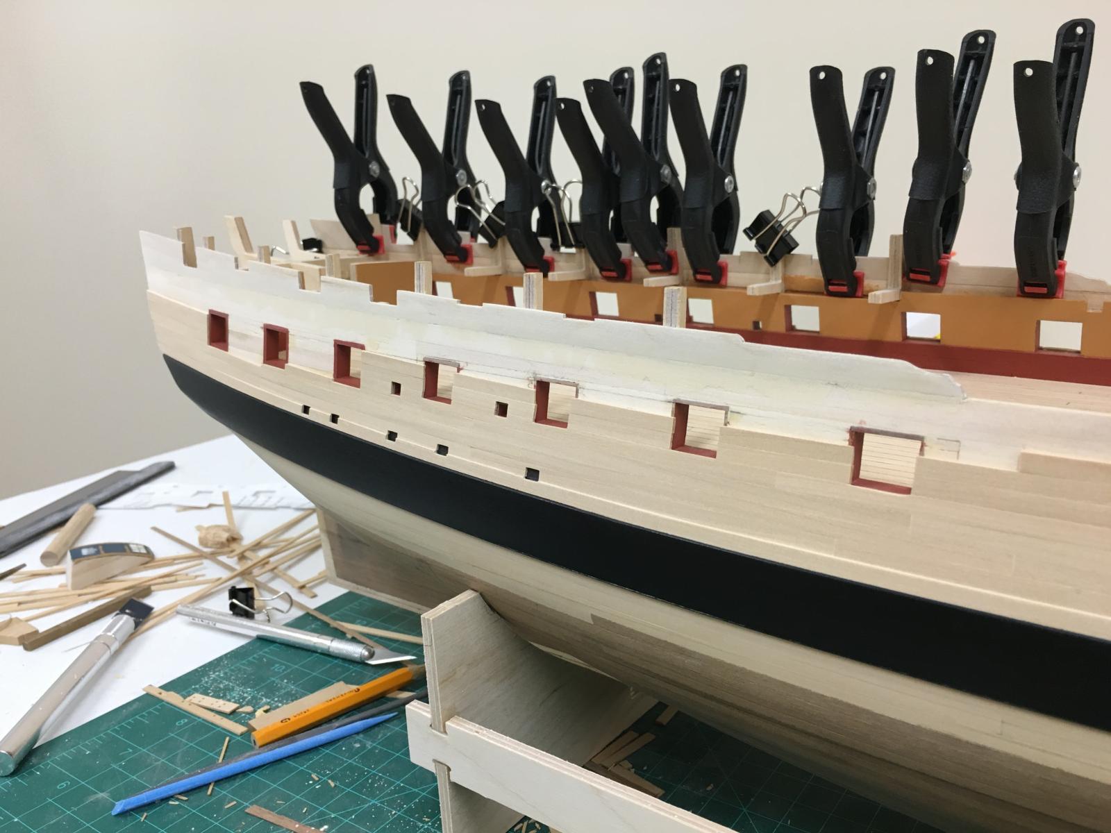
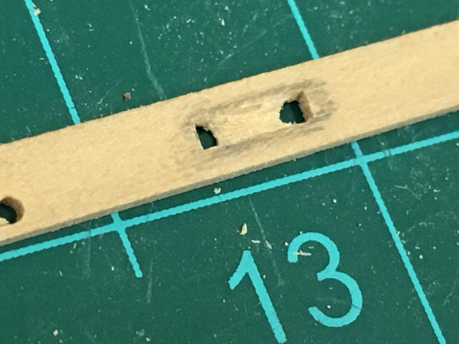
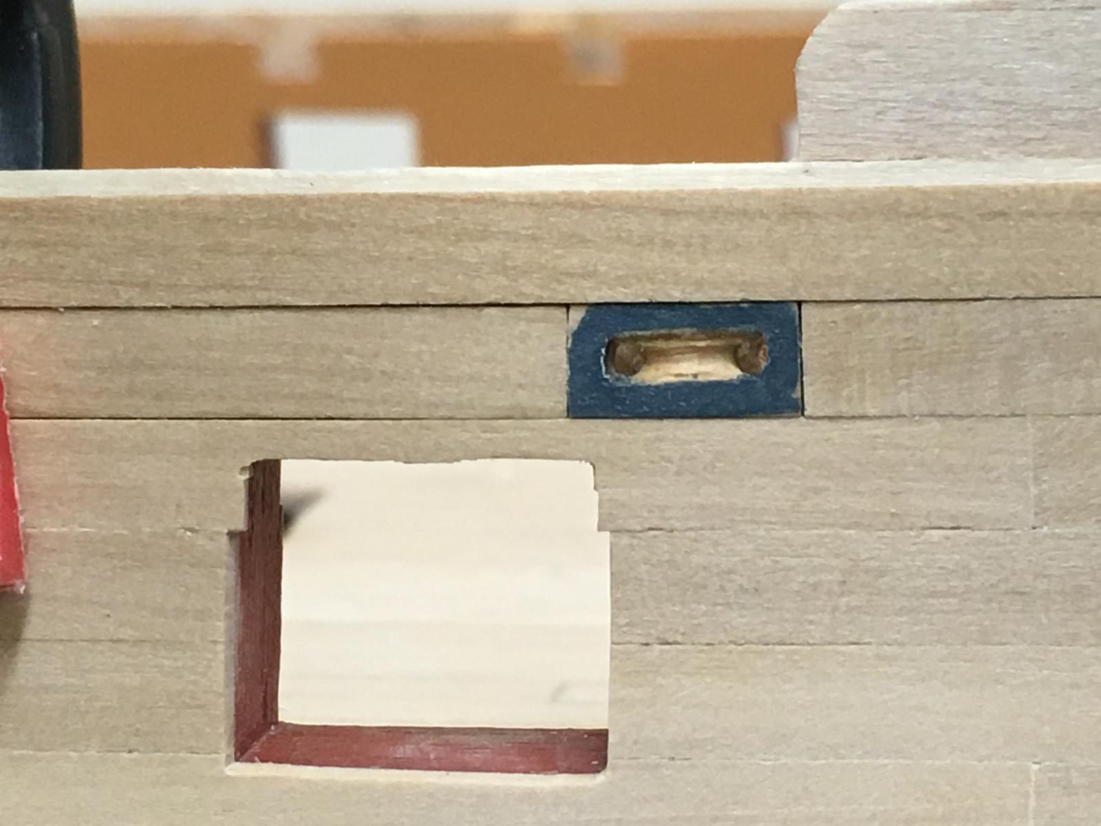
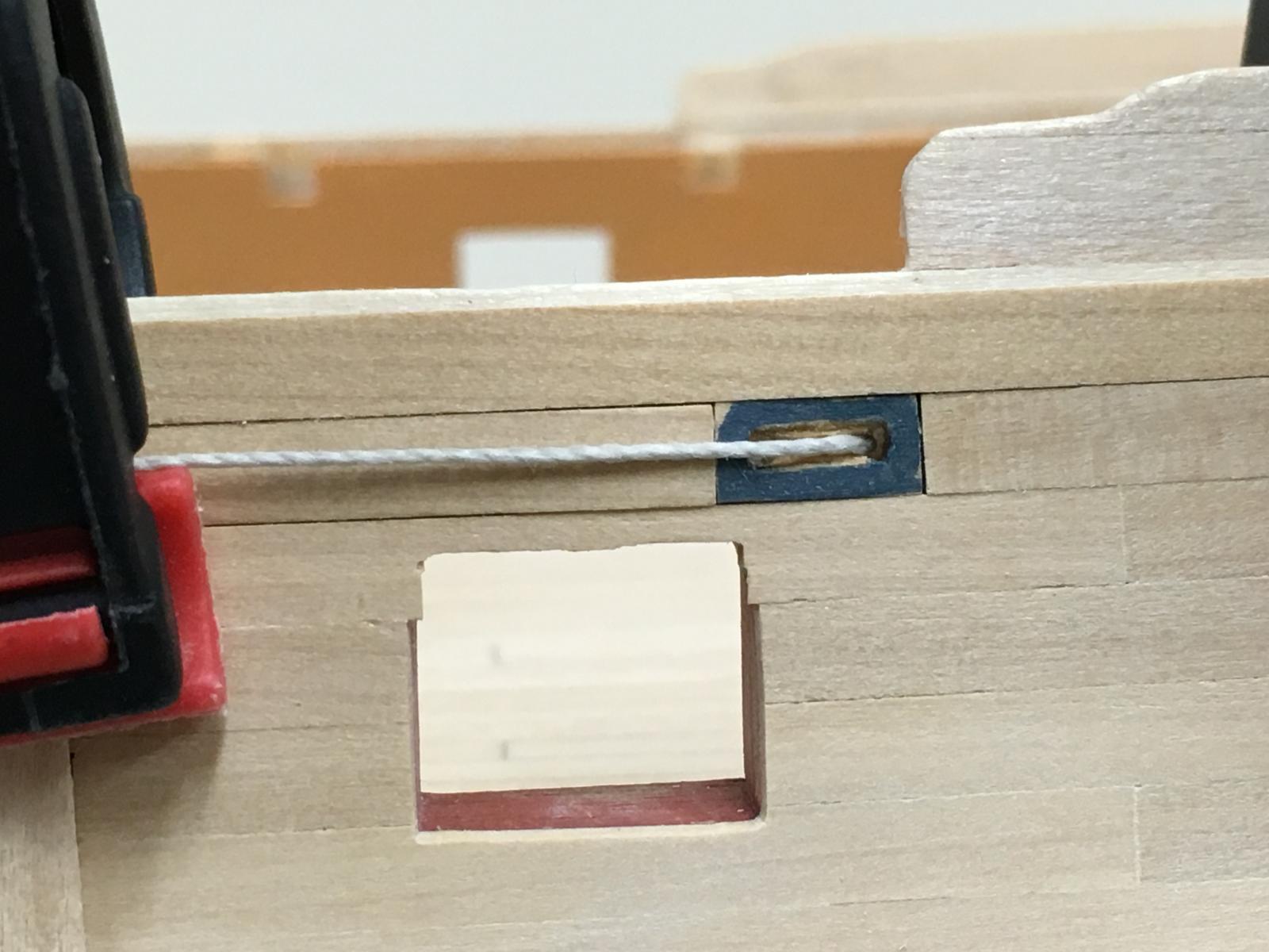
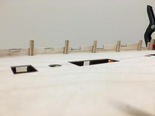
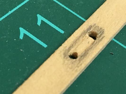
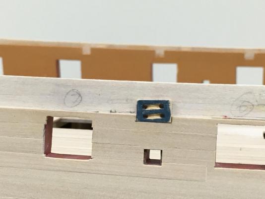
Cheers all and the likes... Carl - Yup, US suppliers call it Castello Boxwood which is similar but not the same, and I suspect it does have a bit more grain Joe - yes, very enjoyable compared to working with walnut Nigel - Great suggestion, although I still have plenty of sanding ahead of me so a little raised grain at this point shouldn't be too much of a problem. Mobbsie - couple of thousand miles help with that Knew I'd forgotten something, the sheaves for the sheets and tacks - wanted to do more than the kit suggest holes. I had originally thought about trying to build the actual blocks but quickly realized very little would be seen even if I did. So took the approach taken by others to simply drill a couple of holes and then shaped a pseudo sheave into some strip. Photos are not great, the super magnification does no favours... Drilled the holes (the pencil is simply to provide a little contrast while working) Used X-acto knife to shape a 'slot' between them A rounded file then provided the profile of the sheave X-acto knife to square the outer edge of the slot Main tack sheave in position. I put on some paint just to get confirm it would look OK once in position (the area of the hull here will be blue). With a temporary simulated tack, demonstrates that even less will be seen... The fore and spritsail sheet block required me to cutout a section from a previously attached plank, wasn't too problematic.


-
Wasn't one of the roles of the Marines to 'protect' certain areas of the ship (esp. lower tiers) to prevent those 'in need' from finding a place to 'do their business' if the 'main office' is fully occupied....not sure I can think of too many other euphemisms. The lower parts of the ship were in any event a pretty putrid place...
-
Appreciate you sharing these details Charlie, the solid hulls seem definitely seem to need a different plan of attack. All looks very neat, tidy and methodical, you've worked up a really nice hull shape.
-
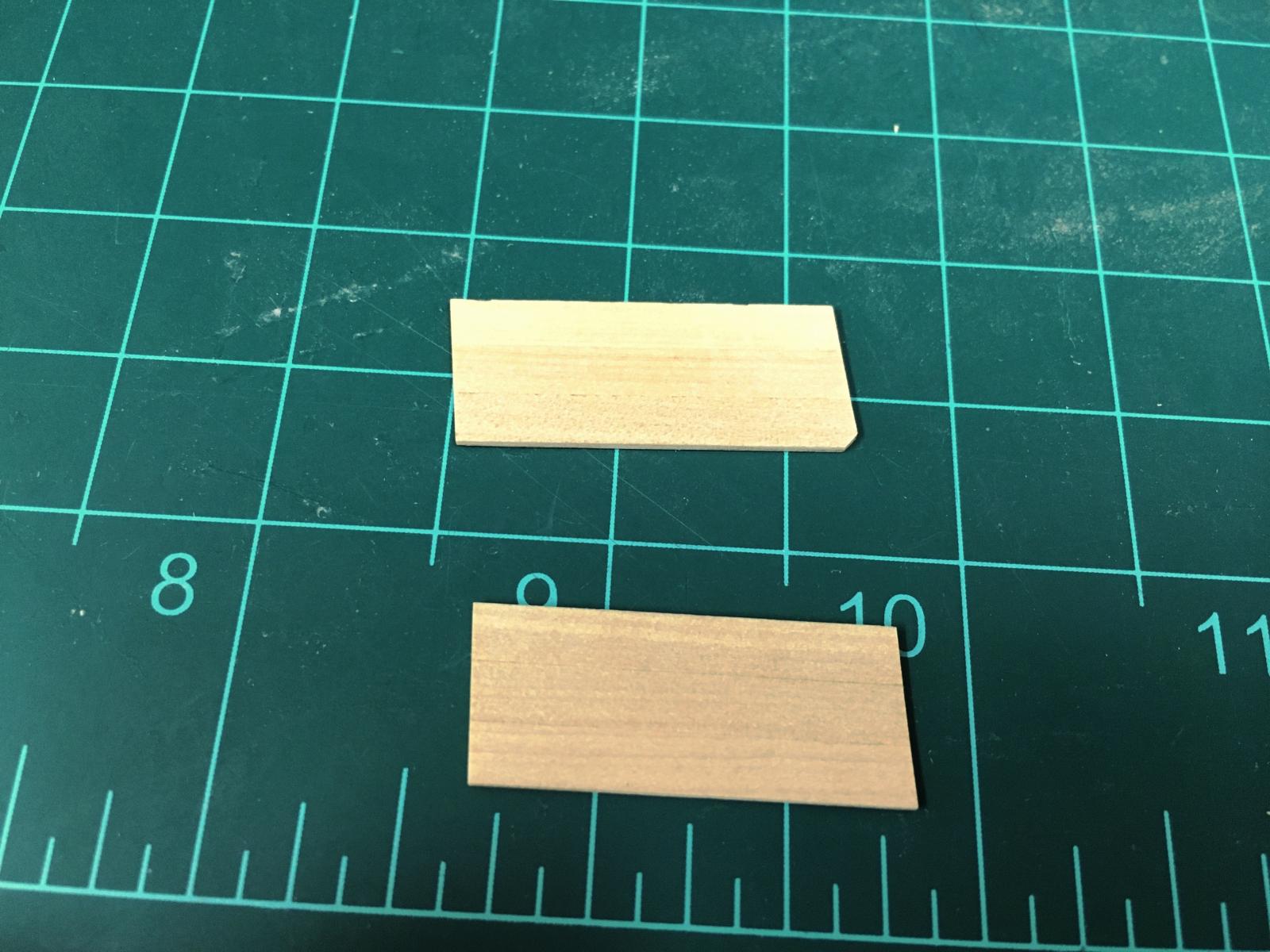
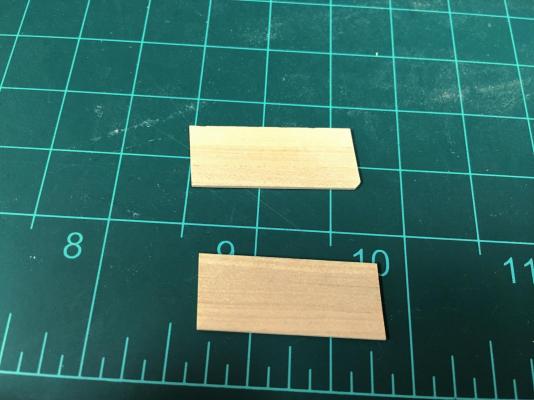
Thanks for the interest and encouragement Pat, Eamonn, Mobbsie, Tom and the likes. Still here slowly cracking away at things. Overall shot, with the unfinished boxwood and dampened to bring out the colour a bit... One thing that becomes very apparent with a finish is the grain in the boxwood. I've been trying to keep this 'harmonious' but its amazing how much the colour and grain can vary in a way I hadn't really noticed on other models. Not sure if my boxwood is just more grainy than average. Anyway, think the finish I'll use will probably not highlight quite as much as dampening with water. Even though I'm not following the exact planking pattern, I'm trying to apply the principles to get some practice. I'm not darkening the plank edges, so they're hard to see.... . This also explains why this is going so slowly. Even around the sweep ports they have need to be built up and keyed in. (Don't know what this type of planking is called...anyone?) One trick I found handy to get as straight an edge as possible on the recessed ports is to edge glue some strip together and shape off the model. Seems to work nicely.


-
Ouch...I have given up following the order that instructions indicate unless I'm convinced its the right way to go, Caldercraft for example don't suggest doing coppering until the upper deck fittings are pretty much in place which doesn't make sense (to me). You seem to be past the ringbolt conundrum, I similarly failed trying to blacken. In the end, I simply stuck hundreds of the eyebolts into a polystyrene sheet and used a dull black primer/topcoat mix from a spray can.
- 1,306 replies
-
- 8
-
-
- syren
- model shipways
- (and 1 more)
-
Ahh, another Agamemnon build to give Sjors some competition. Beautiful build Hennie.
- 214 replies
-
- 5
-
-
- agamemnon
- caldercraft
- (and 1 more)
-
Really nice work and interesting subject matter Mark, definitely want to see how you move forward. It must be nice to have the actual ship to get inspiration from.