


Beef Wellington
-
Posts
2,243 -
Joined
-
Last visited
Content Type
Profiles
Forums
Gallery
Events
Posts posted by Beef Wellington
-
-
As has been said, a 1:64 seventy-four is huge market gap....and so many great subjects. And of course the historic Leda class with 2 living examples...
- chris watton, Canute, thibaultron and 2 others
-
 5
5
-
Nice update David, sharing the challenges of the plansheer myself so appreciate the struggles. Your timberheads turned out very nicely indeed with some very crisp detail, ingenious to use 3D printed jigs. I will undoubtedly be going down the freehand road, but hoping it will be viable to make some less engineered jigs to get the angling correct. The headshots show shes coming together very nicely indeed, well done.
-
-
-
Well done indeed with rounding that 1mm square stock, are you going to try and curve the blade? Big improvement on the kit offering.
-
I can now see it Chris.
-
-
Did you consider painting the details onto the bulkhead rather than using the stickers? Might be worth a try with nothing to lose and could give a much more pleasing result, I suspect that these should really be yellow ochre rather than black, with some light/dark highlights to give some depth.
-
-
-
This model seems to sum up the concept of "less is more". You've done a fantastic job of her, the painting and weathering is very convincing.
- AJohnson, Old Collingwood, mtaylor and 1 other
-
4
-
This looks fantastic Chuck, what is your trick for removing laser char so thoroughly? Everything is so clean.
- mtaylor, Saburo and FrankWouts
-
3
-
Glad you are 'happier' B.E., well justified in my humble opinion. Your tweaks have made all the difference.
- Blue Ensign, Knocklouder and mtaylor
-
3
-
You can view many models on the NMM site which I would definitely recommend. Books are an investment, but some I have invested in are the Rogers Collection Volumes 1&2 and 'The Sailing Frigate' by Gardiner, and 'The Ship of the Line' by Lavery. Both of the latter titles walk you through chronologically the evolution of ships interpreted through existing models. Absorbing all of the wonderful images of original models is something I will never tire of. It quickky becomes clear that there are many variations as has been pointed out. It is also clear that models do not always represent what is probably actual practice on ships - this leads to the first question to think through which is do you want to build a 'model of a model', or a model of the ship as it likely existed - there is bountiful evidence of the former, but not the latter. There are many examples, some of the most noteworthy being that models often appear highly decorated with friezes on blue backgrounds - likely not practical on a real ship, but very appealing to model makers when it seemed to be in fashion. The other consideration would be availability of paint colours - during the period in question, many colours existed but would have proved prohibitively expensive to all but the richest captains - so its most likely that red and yellow ochre predominated given its availability and low(er) cost. This does seem to be reflected on most contemporary models, which do not typically show multi-coloured stern decorations (or gold which seems to be some people's preference). Moving into early 19th century, white and green paint became more fashionable, and affordable and these started to replace the 'ochres'.
These, and many more considerations suggest, as has been pointed out above, that there is not really a 'correct' answer, the best you are likely to achieve is 'directionally correct' 🙂
For what its worth, I am shamelessly taking the 'model of a model' approach for 'Jason', it is highly unlikely that any of the Artois class would have been so beautifully decorated. Indeed the only print I can find of 'Jason' shows her with the ubiquitous black hull with a stripe between gunports.
-
Congratulations Mike, you should be very proud of the excellent result!
- AJohnson and hollowneck
-
2
-
-
Thats a very nice treatise on rigging Mike! I think your efforts to show this for future Snake builders will be very valuable. Shes looking fantastic, very well done.
- hollowneck and AJohnson
-
2
-
-
@Wayne - I miss seeing progress on your Enterprise, hopefully soon (?) That will be a beauty!
@Mark - I aspire to be able to do what your are achieving on your excellent Le Rochefort build, would love to do a POF one one day and I need to bone up on basic woodworking techniques first.
Quarterdeck plansheer (capping rail?):
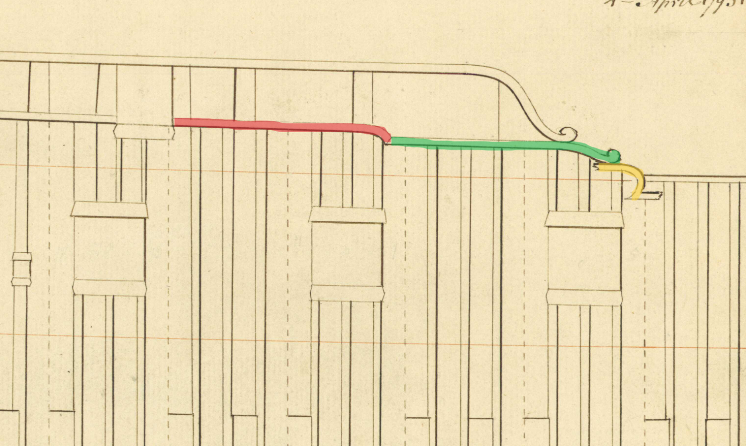
Work can now commence on the quarterdeck plansheer given that the upper hull profile is finalised. This will be a rather long process given the many breaks in the smooth run of the plansheer. Starting with the quarterdeck, a 'lego' type approach was taken to build items individually and then combine on the hull. While more time consuming (what does that matter!), my feeling was that it would give more control over the outcome. 3 pieces will be needed, and will be referred to rather unimaginatively as pieces 1,2 and 3 becuase I have no idea how better to refer to them. (Given that 2D plans don't seem to translate 3D, I have attempted to study as many pictures of contemporary models, plans and the many high quality builds here - all I could really glean was that there are many ways to approach this, and this approach is probably a compromise.). This is the area I'm talking about:
- Piece #1: from the gunwale, around the main drift volute to the terminaton of the scroll decoration (yellow)
- Piece #2: middle section with a scroll type detail on one end (green)
-
Piece #3: section following the profile caused by the break of the quarterdeck drift rail to the main rail (red)

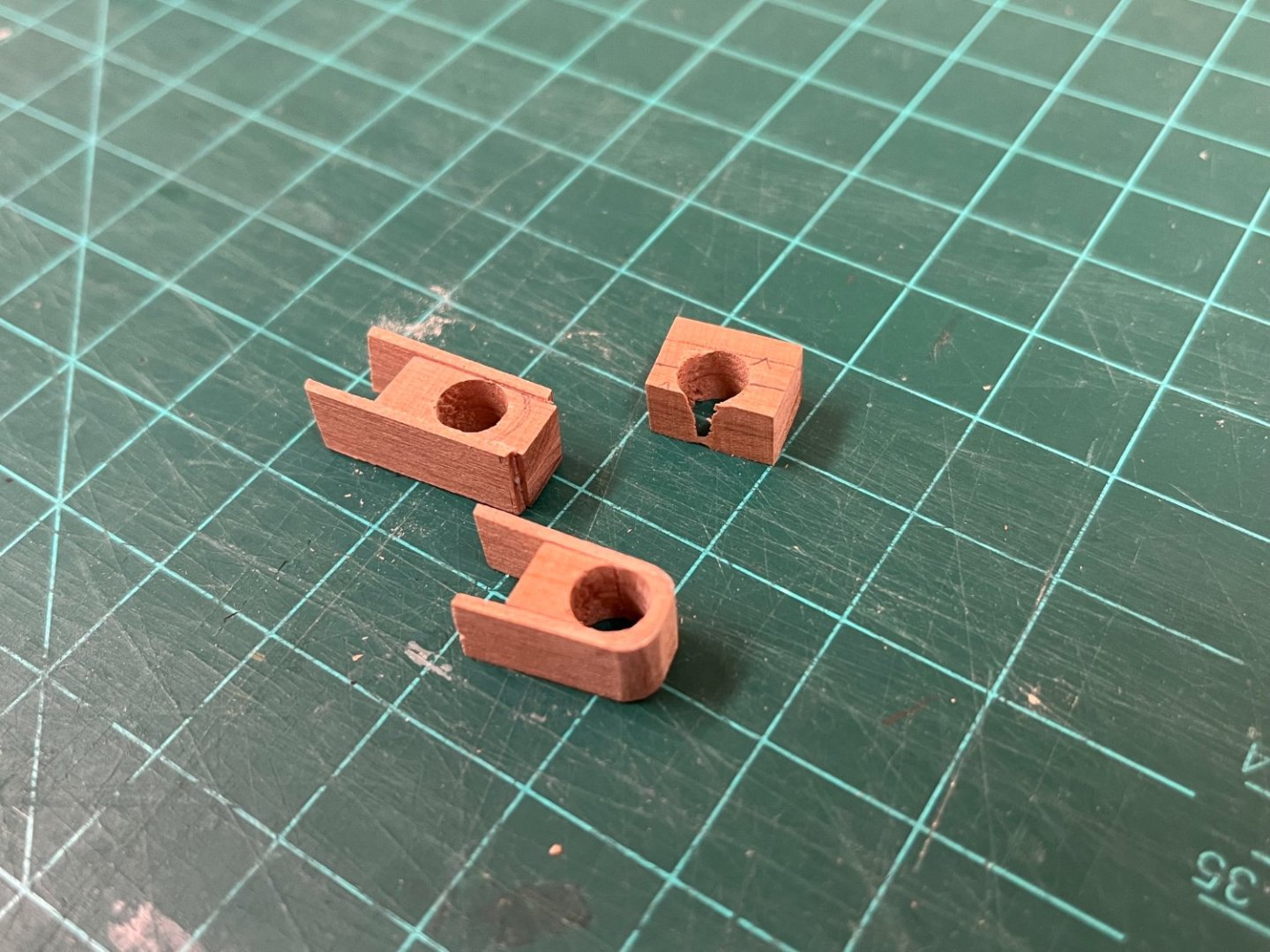
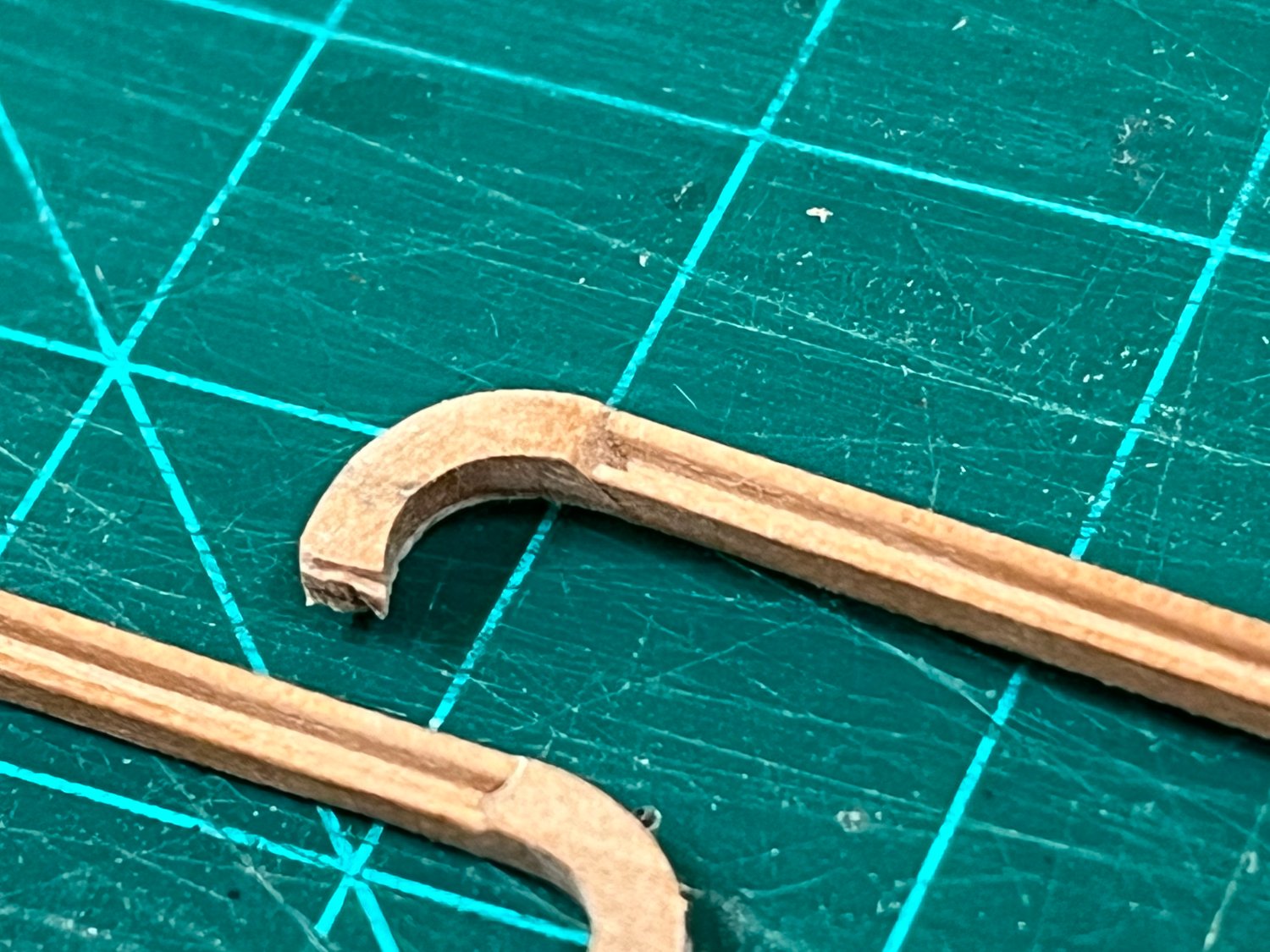
Construction of Piece #1:
Without anythig sufficient thick to hand, 4mm pear sheet wood was laminated together and ever increasing holes drilled until 6mm had been achieved (curvature of volute top). A hand drill had to be used for this as I don't have a drill press. Care was taken to ensure that the grain was running perpendicular to the hole which I suspect will give the strongest final result. The hole was then very carefully reduced on the circular sander until just before the hole was opened up. (I managed to do this on both sides which allowed 2 sections to be made from one hole). 1mm thick strips were then attached on each side, with PVA glue only being used on one side and clamped. Once thoroughly dry, the piece was roughly shaped toward its final form of a 1mm thick curve. The part was cut in half, releasing each curved section for final finishing using sanding sticks. (Note: the downside of only having a hand drill means it is very difficult to get perpendicular holes, and the top block shows a failure to allow for this).
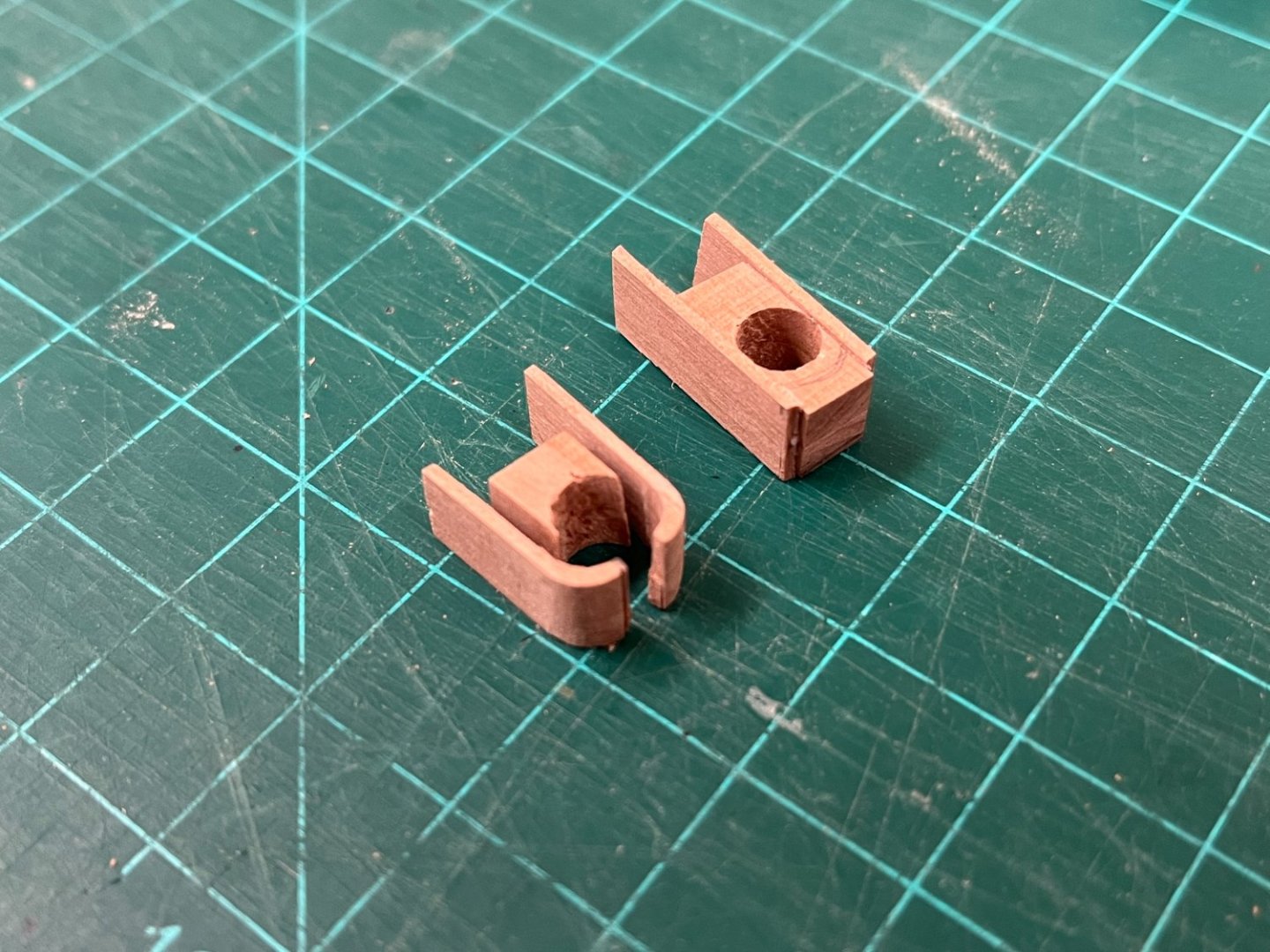
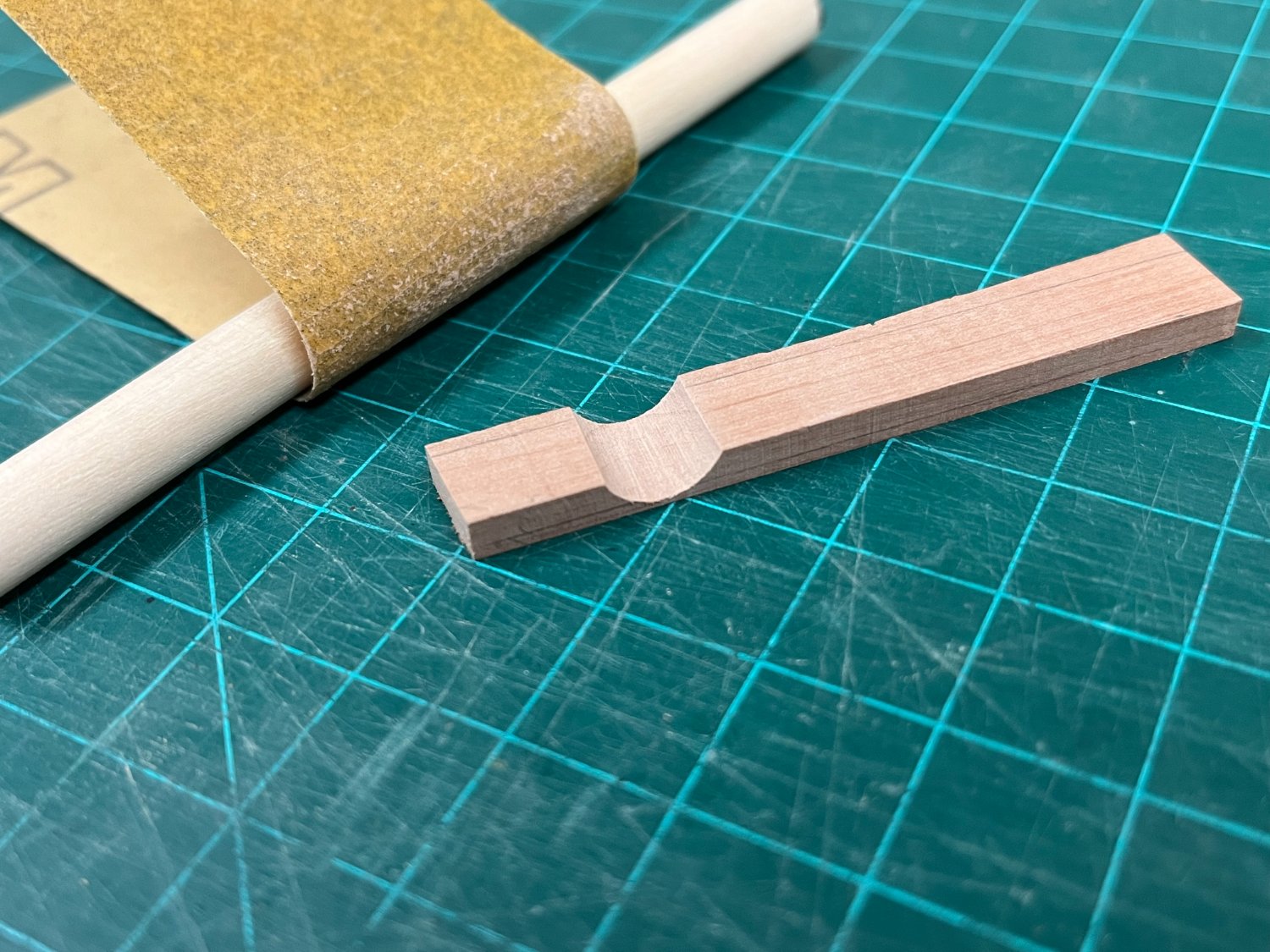
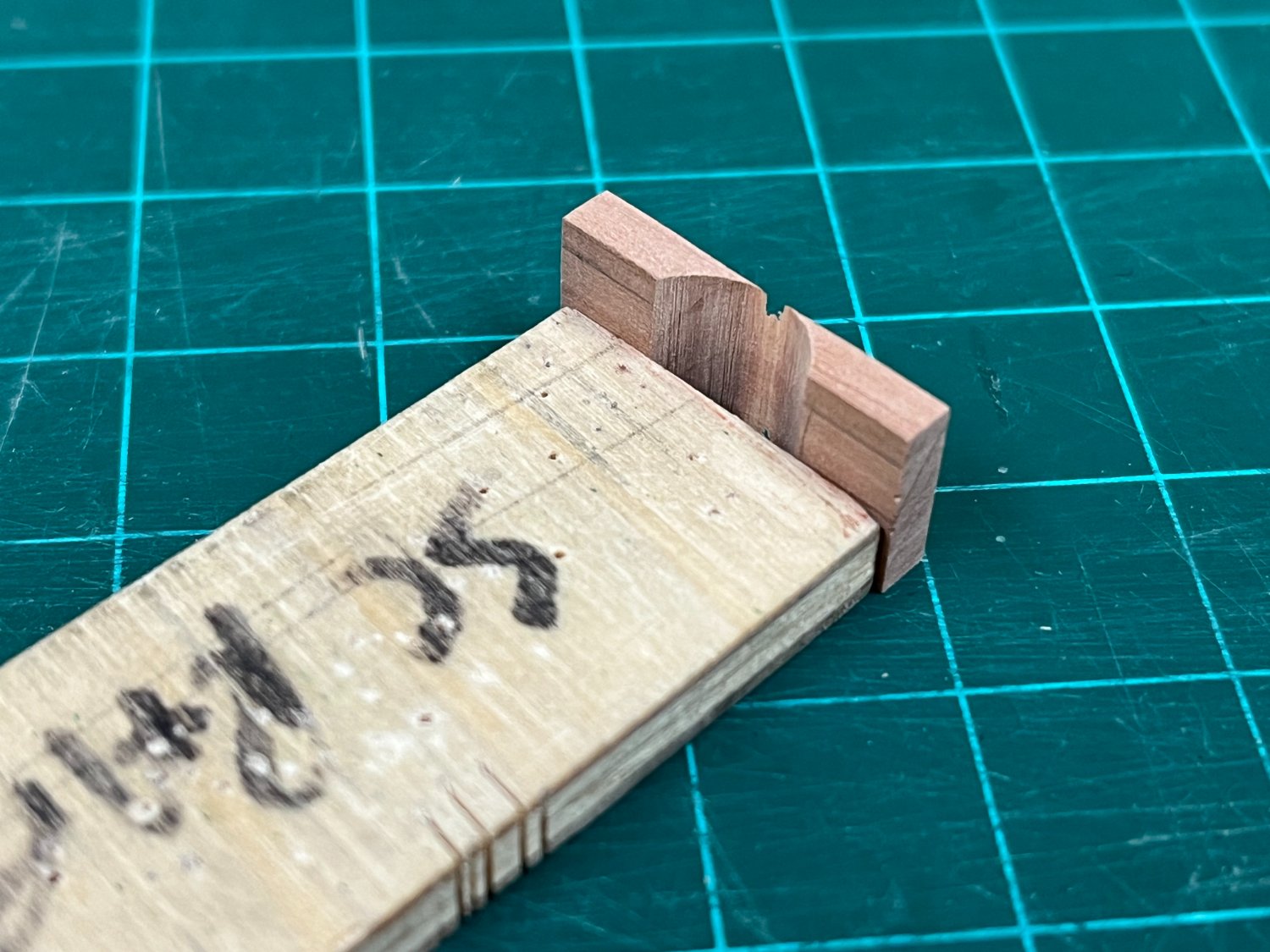
Construction of Piece #2:
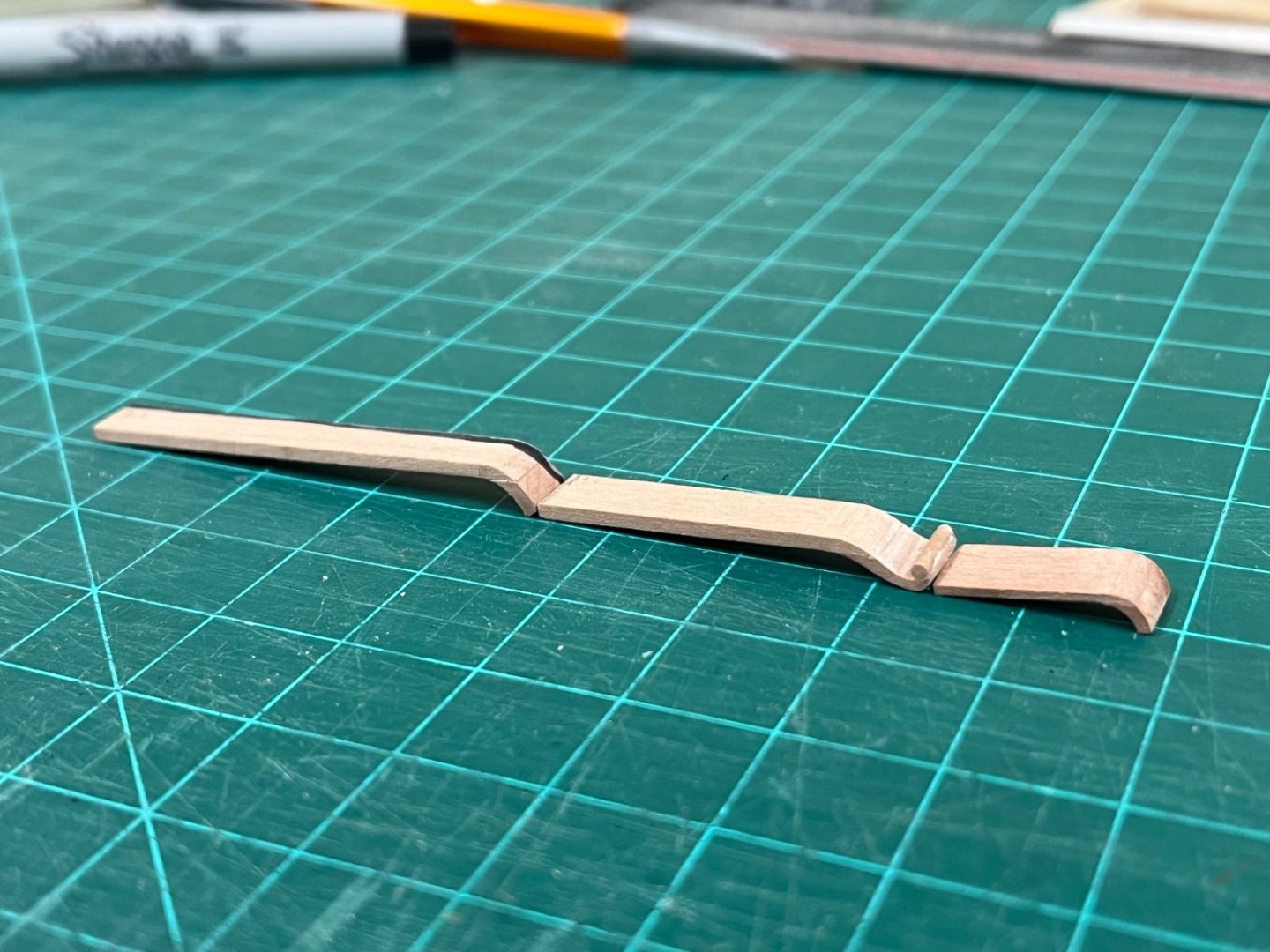
The scroll detail is probably the most complicated item to deal with. To start, sandpaper wrapped around a section of 6mm dowel and a curved profile introduced into some 4mm cherry sheet. The section was then temporarily glued to some scrap to allow the excess material to be carefully removed on the circular sander, (a technique that is becoming very familiar!). The two halves were detatched, and glued to a pre-shaped section of 1.5mm thick pear because the curve of the hull is a factor. The first photo below shows this starting point from which the final form was shaped. The second photo shows progress mid way through shaping. To account for the scroll detail, a circular needle file was used to introduce a profile into which some pre-made 1.5mm pear dowel could be glued.


Construction of Piece #3:
This was constructed in exactly the same way as piece #1, only difference being that 1.5mm was used for the plansheer.
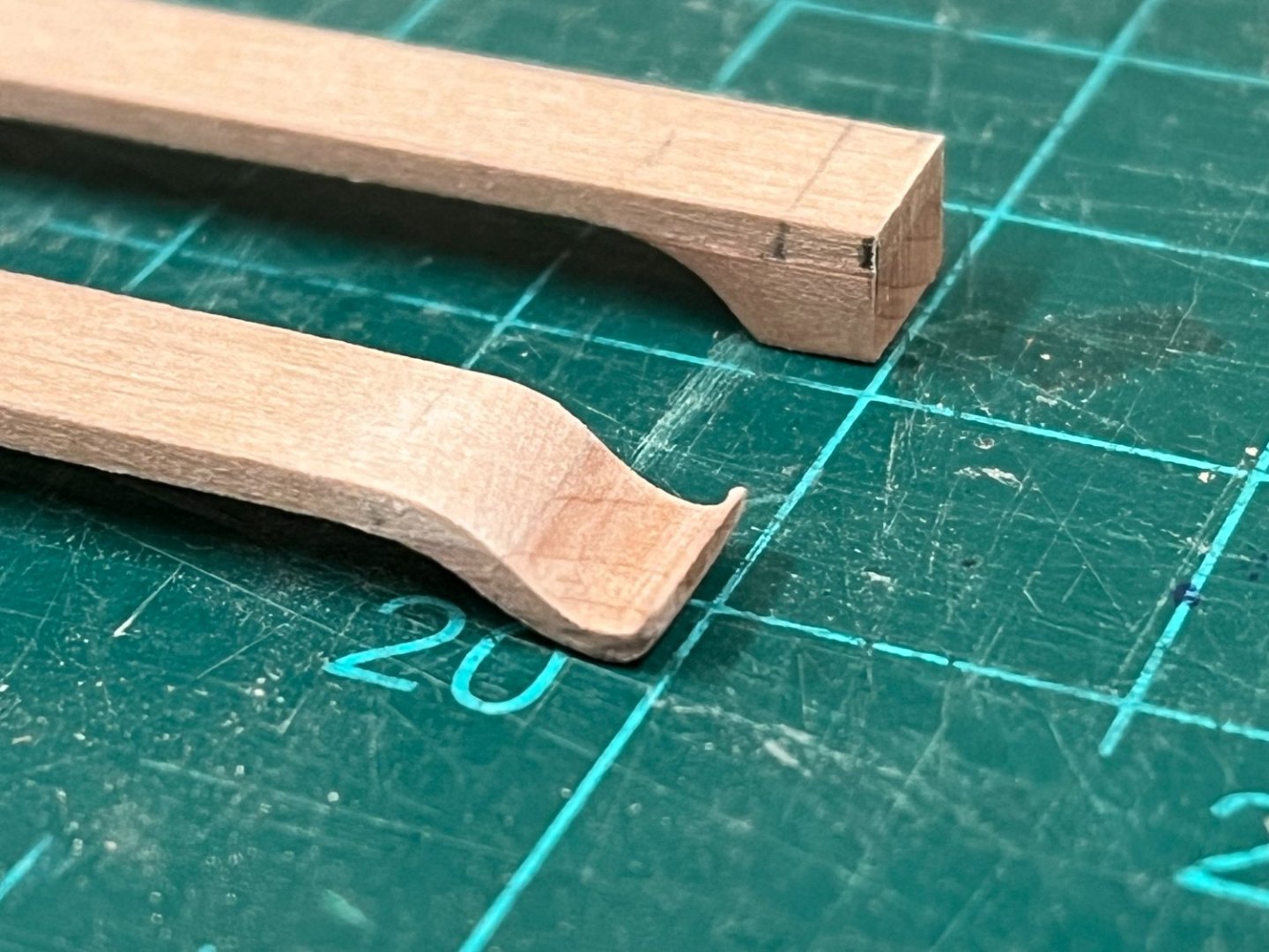
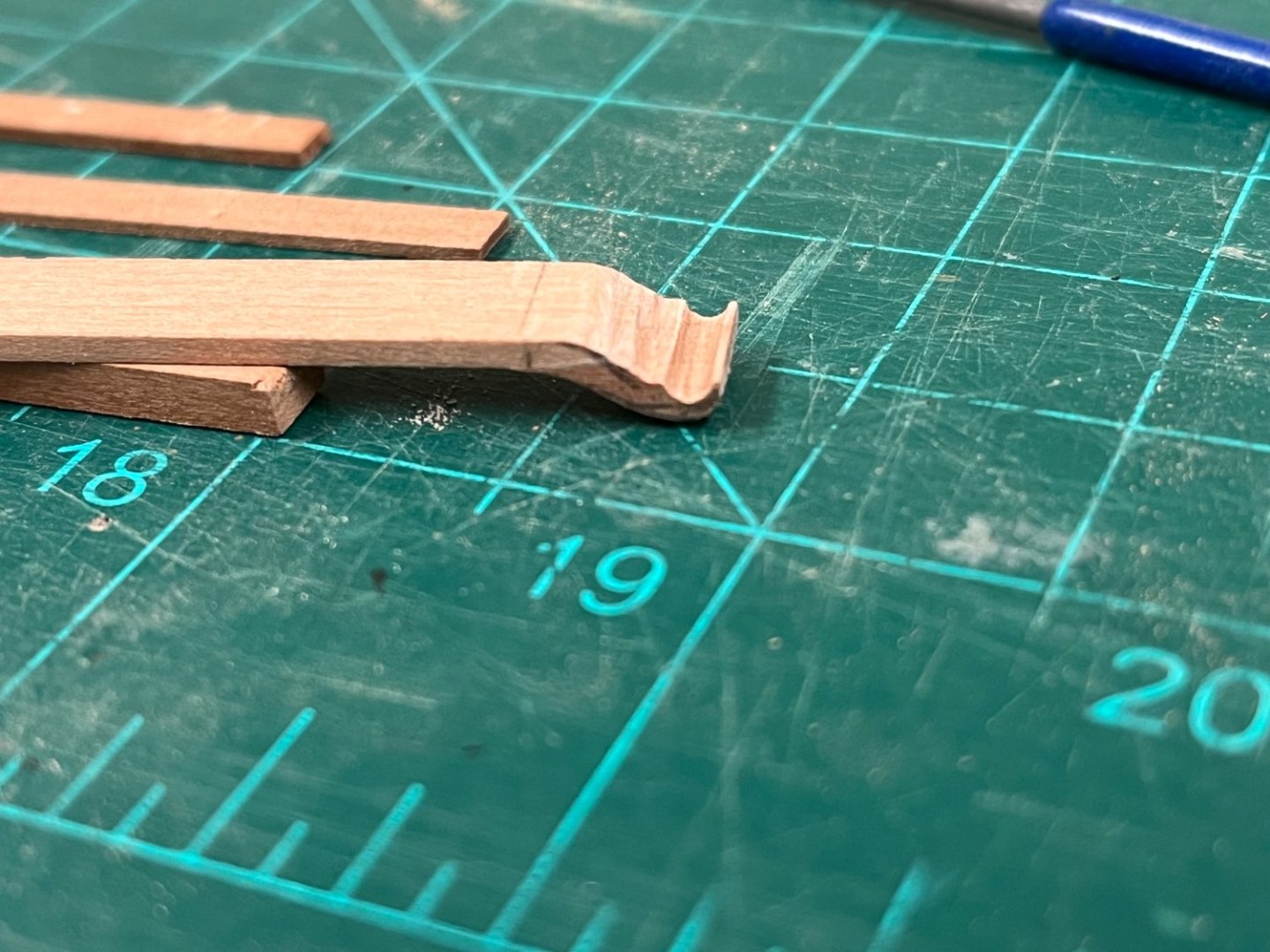
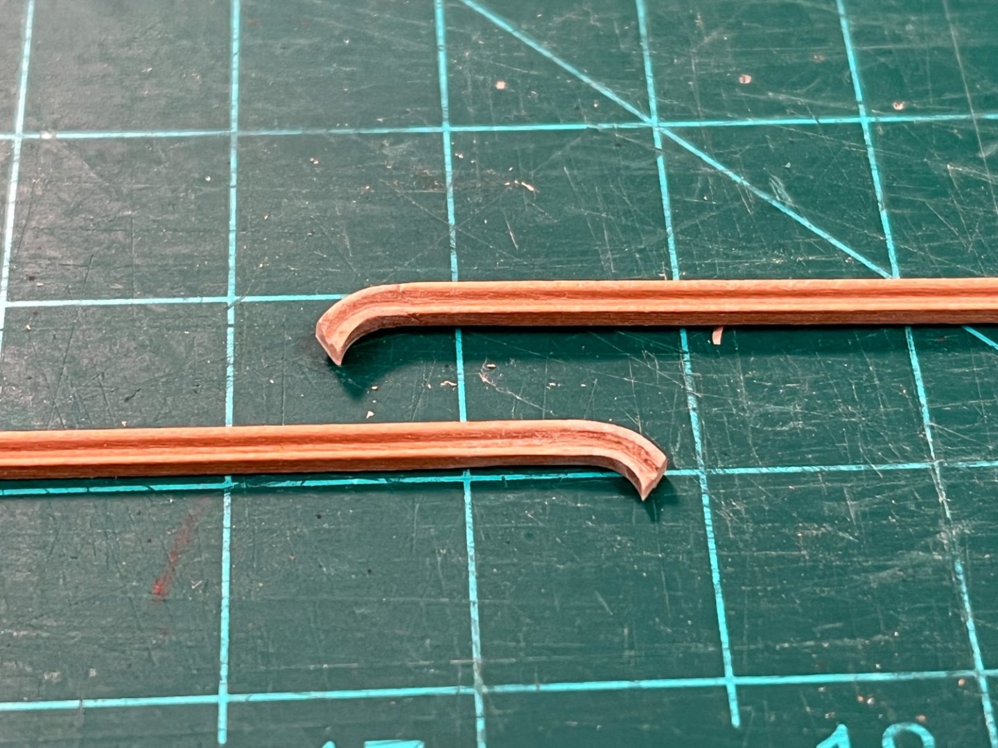
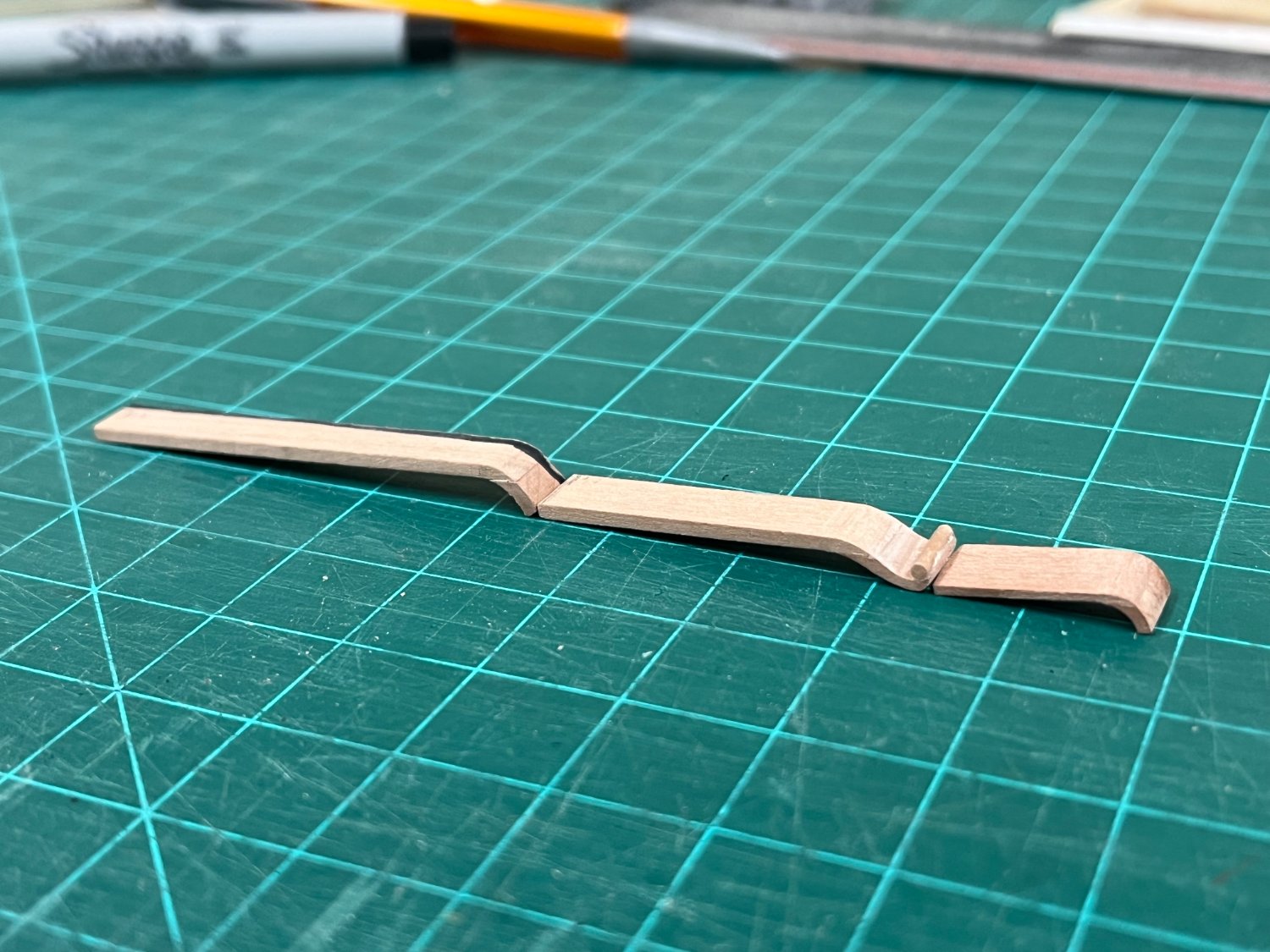
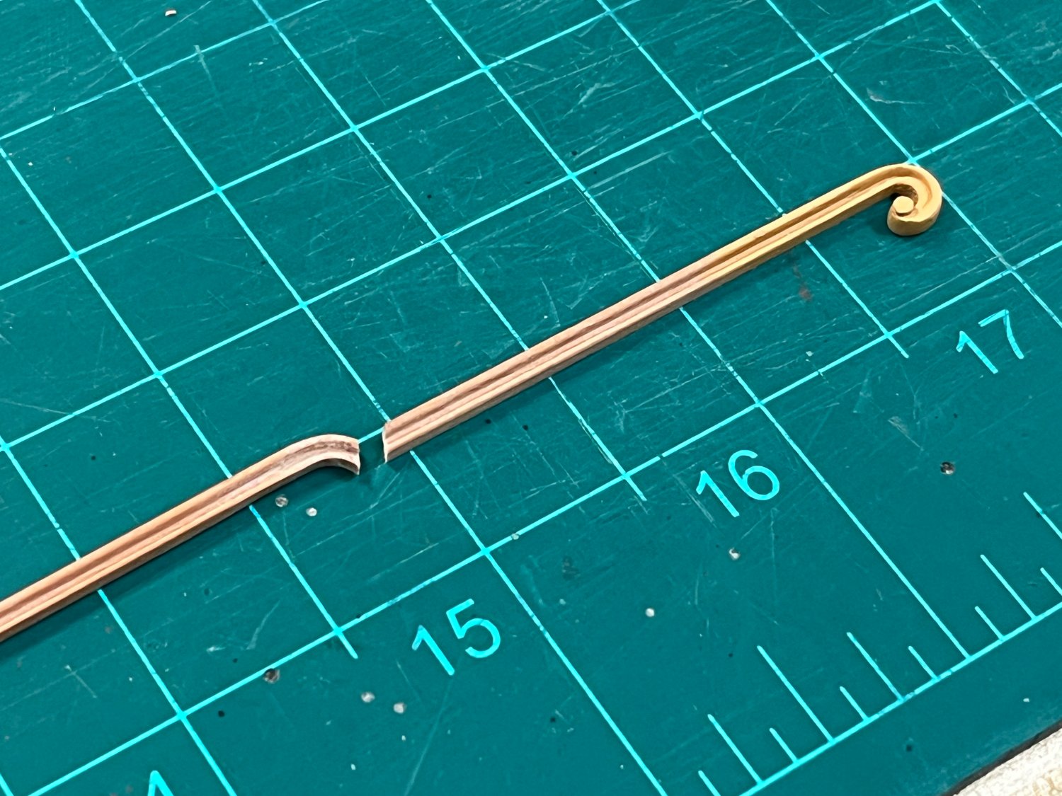
Once each step was completed, the pieces can the be individually fine tuned prior to installation, each having deliberately been made a little long. A profile was introduced in the usual fashion using a profile cut into a safety razor blade (see final pics below):
The curved sections proved not unexpectedly to be the most challenging to fine tune. The aft end of piece #3 terminates in a gun port which would be relatively easy to finish when the time comes, so this was fitted fitted first. The most worrying thing here was coping the angle of the curved portion to tie into the aft end of piece #2 to avoid a time intensive redo (65deg was found to be the solution). Piece #2 was then very carefully shortened until it sat correctly. Before piece #1 could be finalized, the gunwale was made up to ensure correct positioning and shaping as piece #1 will butt up against both.
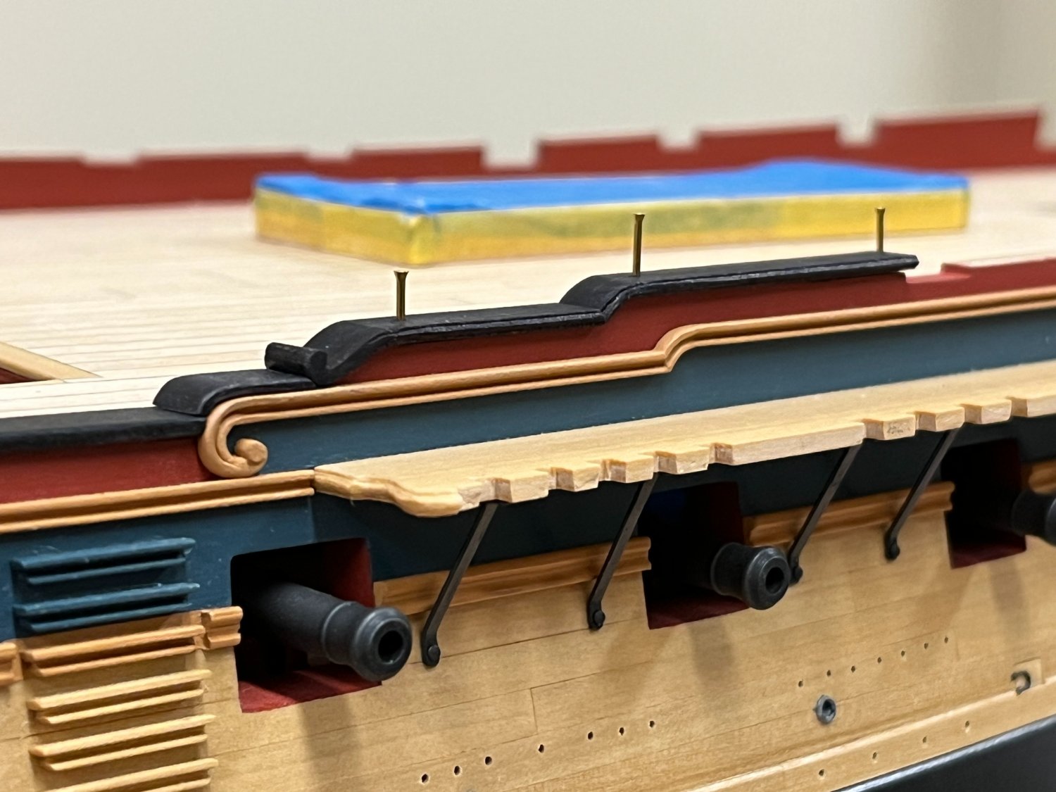
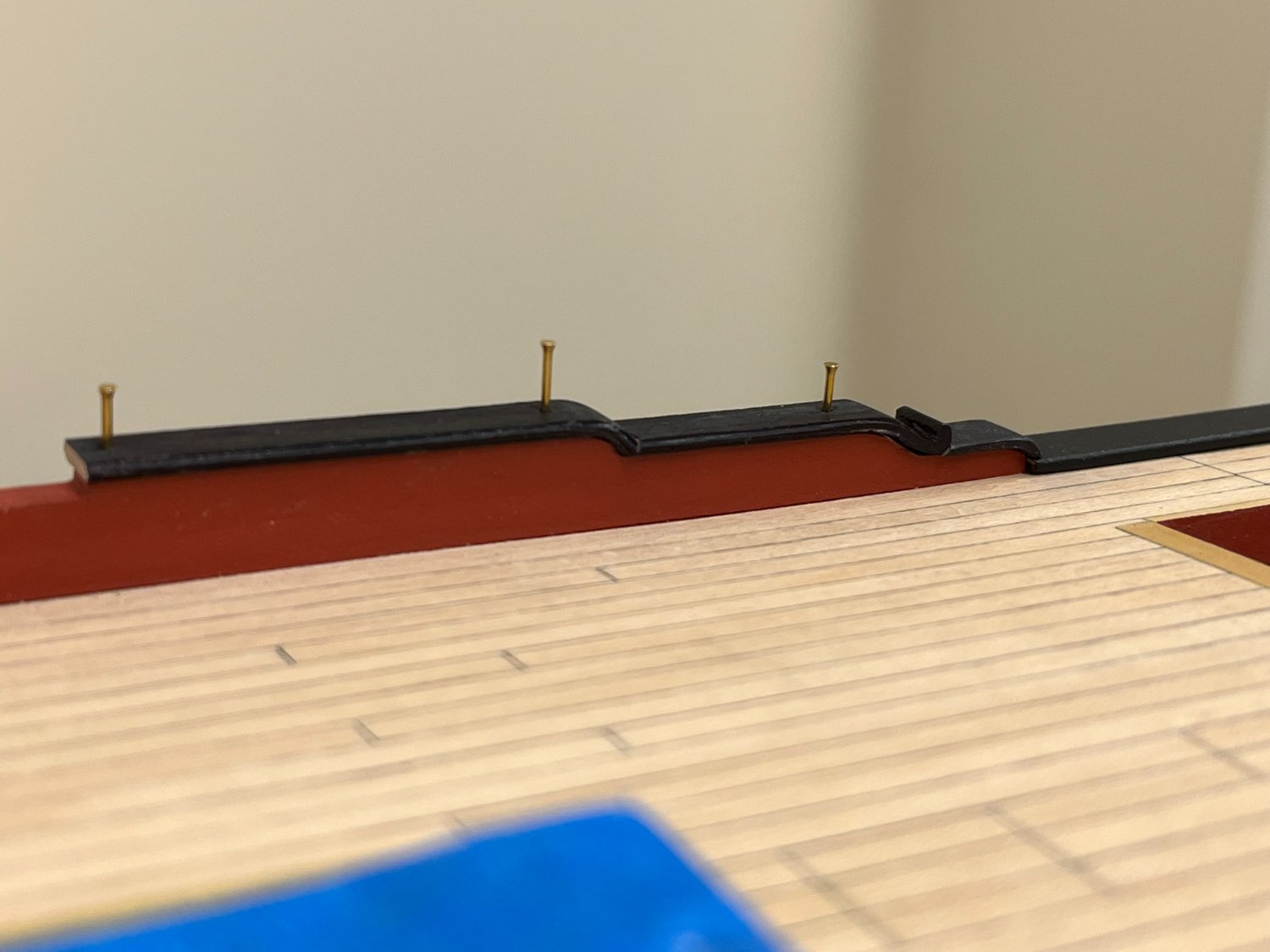
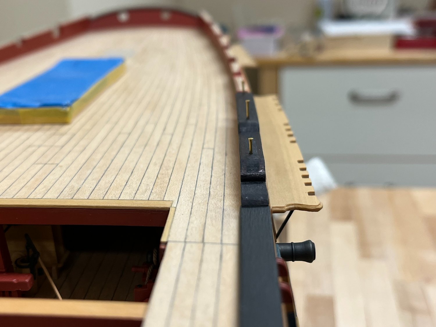
And the results...
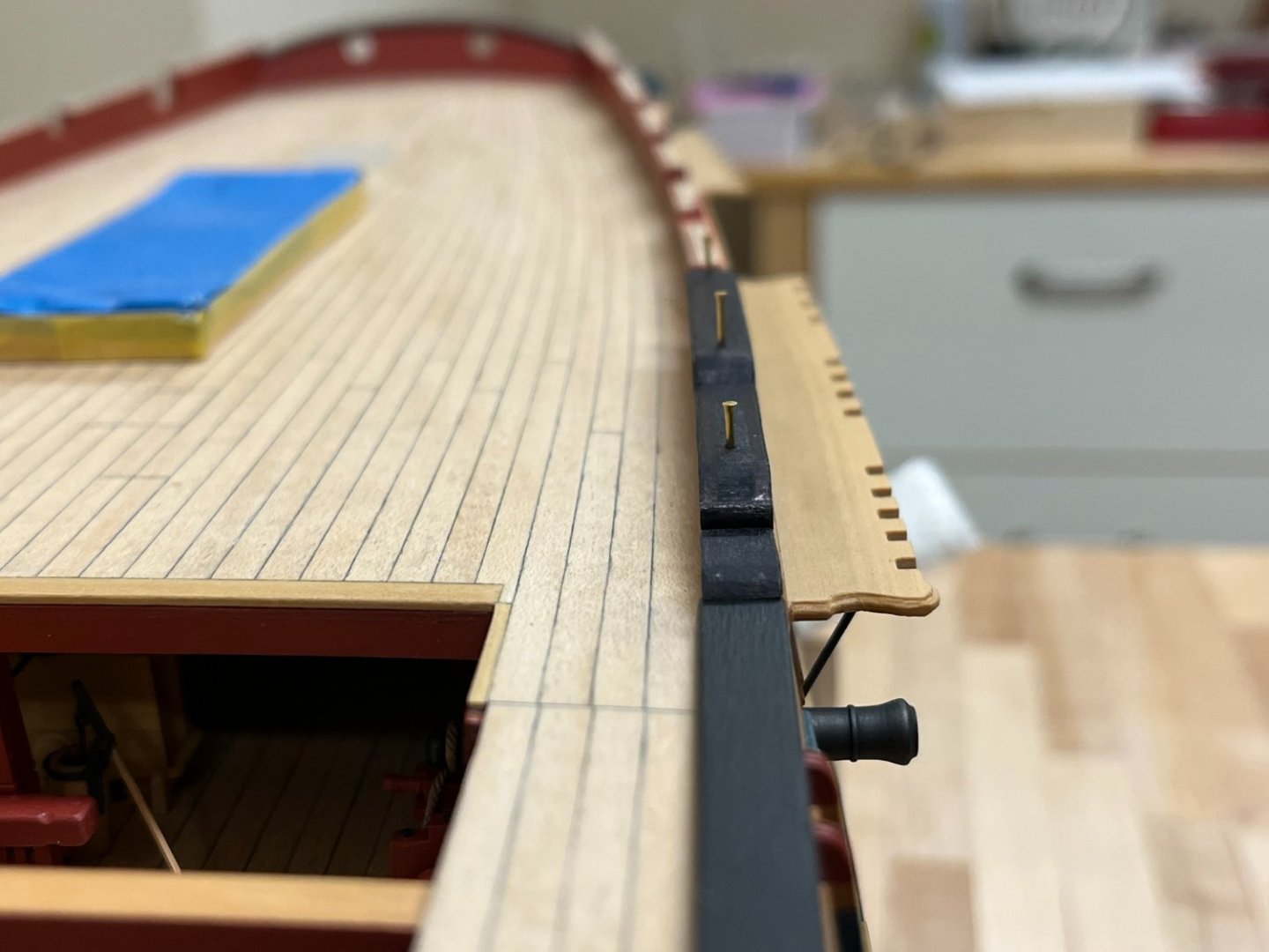
Everything is dryfit only for now. Pins were used to temporarily hold the various sections in place, these can be easily filled, although efforts were made to place these where the timber heads will cover them. With the exception of the gunwale, the plansheer sections have not yet been painted but have been coloured with artist pens to help my eye determine final proportions. The final shot below shows how even the relatively minor curve of the hull at this point needs to be accounted for. I have a lot of work ahead of me to finish off the other areas so will likely be a while before another update, but must confess to be being very pleased with the way this turned out.


-
Thanks everyone for the continued interest. Catching up on a couple of items before moving onto the more complex task of the sheer rail (plansheer?, capping rail?) which will be the focus of the next update. The profile of the hull has been fine tuned, all of the gunports have been cut, fettled, and the upper hull painted. The only remaining task with the rails is to create the transition from the quarterdeck drift rail and the main rail. A similar approach was taken to that used for the volutes to introduce the curve, but a 45deg joint was used to try and leverage the pre-scraped profile as much as possible. The profile was then introduced into the curved section as described above for the volutes. Once complete, this section was joined with the volute section before gluing in place.


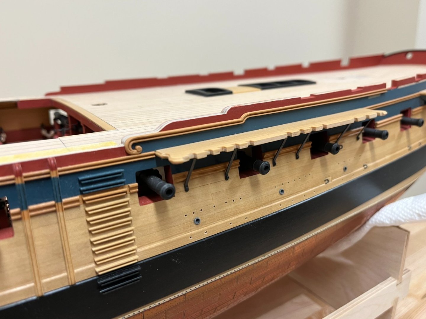
And the rails finally attached the hull. The curve of the forward end of the bulwark follows that of the volute. Visually its important (to my eye anyway!) to ensure that all of the rails and top of the hull are parallel, and follow the sweep of the main wale. Placement of the rail also helps determine the appropriate final profile of the upper hull.
-
-
Just found you again BE, thankfully before you're finished. The small boats are fascinating and this is definitely one that has tempted me. I'm amazed that the flying transom only became detatched once, and have no doubt that the silk purse is not far away...definitely agree on the replacement of the transom panel.
- Wintergreen, mtaylor and Blue Ensign
-
3
-
-
Looks great, definitely intriguing to see how this beauty develops!
- FrankWouts and mtaylor
-
2


HMS Jason by Beef Wellington - Caldercraft - 1:64 - Artois-class frigate modified from HMS Diana 1794
in - Kit build logs for subjects built from 1751 - 1800
Posted · Edited by Beef Wellington
Work continues slowly, but not really anything that would be noticeable in a photo update. In a shameless attempt to cover this up, sharing some contemporary print images that I've been trying to get my hands on for quite some time now. (The 3rd print below first appeared in my second post in this log back in 2014...ahem...I'm including here for completeness). Three of the four are by Robert Dodd, and the other is by John Fairburn, and correlating with NMM records, were contemporaneously created between 1798 and 1801. Its hard to corroborate the details between artists because the Robert Dodd prints are of a much higher quality - a comment on Dodd reflects that he is likely a reasonably reliable source "Although technically accurate and meticulous, his artistic talents were somewhat eclipsed by the greatest of his peers, and it is his contribution to the historical record that is his greatest legacy". Considering that the representations were 'inscribed to' the ship's captains, one might think that they would be accurate on key points.
Full details below, but a couple of things jump out, nothing here will change the approach being taken on this build, but may be of value to others. I'm really hoping I can get my hands on building contracts now.
Sequel to the action between L'Hercule and Mars (April 21, 1798): Artist: Robert Dodd ca.1798
Inscription “Sequel to the Action of L’HERCULE and MARS, on the Night of April 24th 1798. Representing the MARS bringing her PRIZE out of the Passage Du Raz, the JASON FRIGATE having come up some time after the ENEMY had STRUCK, assisting in shifting the Prisoners.”
Capture of La Seine: Artist: Robert Dodd
Inscription “CAPTURE of LA SEINE most respectfully Inscribed to the Captains STERLING & MILNE. This Action commenced in a running fight between LA PIQUE and LA SEINE the former was disabled by the loss of her Main Topmast and the JASON coming up between & received the fire of the Enemy Her Action continued when the [unreadable] Ships grounded on the French Coast near Midnight LA SEINE still making a most exemplary defense, and did not surrender until totally dismasted with the loss of 170 Men killed & 100 badly wounded”
A REPRESENTATION of the JASON 38 guns capturing LA SEINE: Artist: John Fairburn, 1 Oct 1798
Inscription “A REPRESENTATION of the JASON 38 guns capturing LA SEINE, a FRENCH FRIGATE of 42 Guns near PENMARK ROCK, June 30th 1798 The La Pique Frigate had engaged the La Seine for a considerable time, before the Jason came up, but did unfortunately run aground in the action & bilged & was afterwards burn'd by her own crew"
Situation of Jason and La Pique the morning after the engagement: Artist: Robert Dodd
Description taken from NMM: A depiction of the British frigates Jason and La Pique on moderate seas, flying the British ensign, with their prize, La Seine, on 29 June 1798; troops can be seen on land in the distance. The Jason is shown in the foreground in port-broadside view, behind her is La Seine with her masts cut off; La Pique (port quarter view) is on the right in the process of sinking, shown with her crew climbing down on to a rowing boat. Several other rowing boats can be seen in the foreground. The sails of the Jason and La Pique show extensive damage from cannon fire.
Inscription “SITUATION of the JASON and LA PIQUE with their Prize on the Morning after the Action. Representing the Jason as just having hove off the ground. La Pique being unfortunately bilged was cleared of her Stores and destroyed by her own Crew, the wounded Men of the Enemy were put on Shore and given in charge to a division of their [unreadable] ARMY of ENGLAND who appeared in numbers on the Beach unable to molest(?) the British Ships or prevent their captured Frigate from being brought off.”