


Beef Wellington
-
Posts
2,243 -
Joined
-
Last visited
Content Type
Profiles
Forums
Gallery
Events
Posts posted by Beef Wellington
-
-
I think 'raised wooden welcome mat' is probably the best answer, it is a nice detail. I wonder if its practical application would be to reduce tripping hazzard when entering/exiting as it is at the same level as the floor of the entryport and step. I just can't think of a sensible drainage explanation.
-
-
Mark - your work is outstanding and inspirational, such clean woodworking. One question if I may, how do you shape the underside of your beams? The concave profiles must me challenging than the convex upper side.
- Keith Black, mtaylor and No Idea
-
 2
2
-
 1
1
-
-
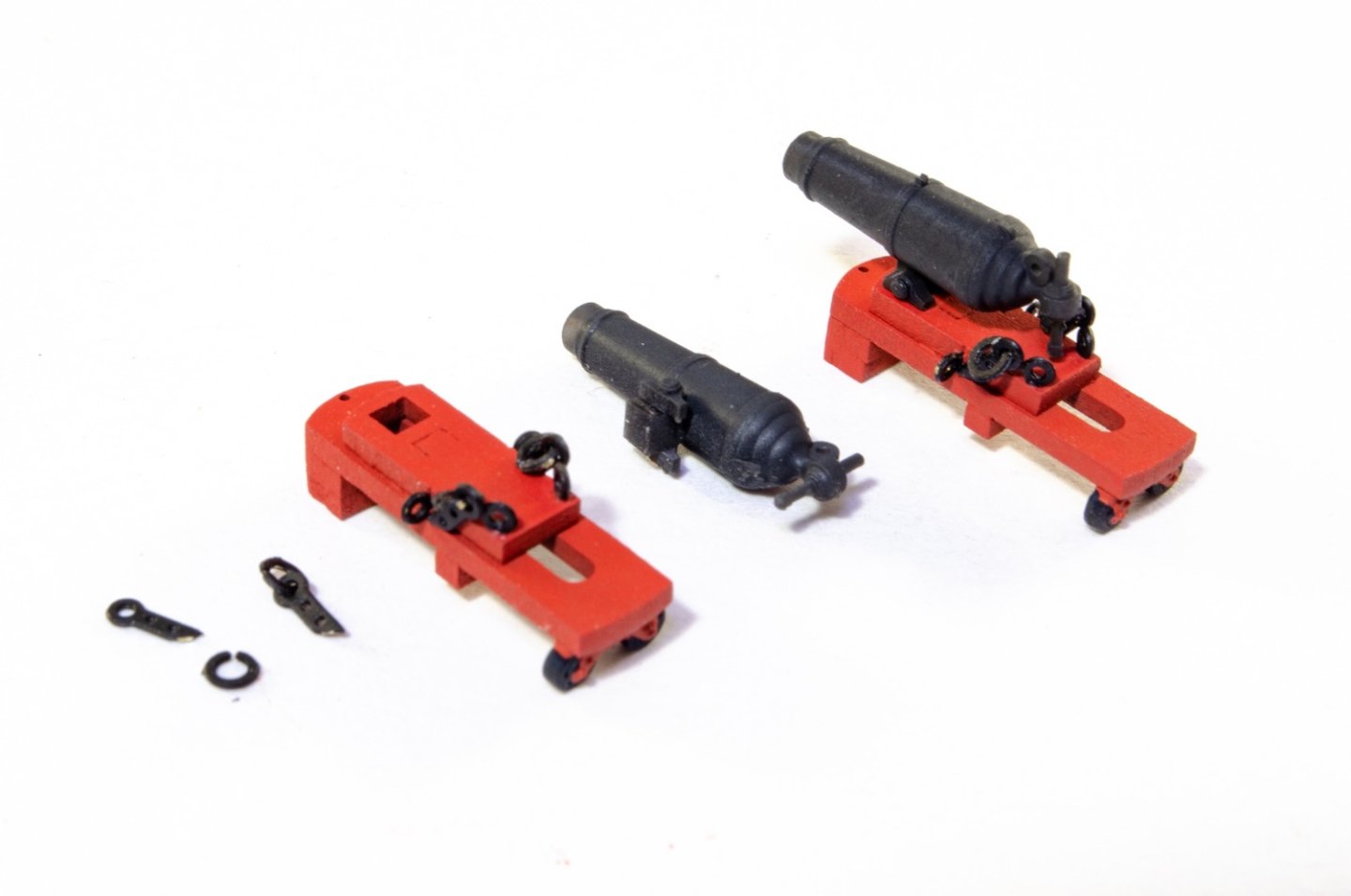
This looks like a great kit coming together! Question maybe for Chris, I see the carronade beds that will be provided look to have a molded wheel arrangement vs the flat PE wheel arrangement that is currently available. Will these be available to buy separate from the kit? They look so much better.
- yvesvidal, thibaultron, BobG and 4 others
-
7
-
-
Headworks (Part 2):
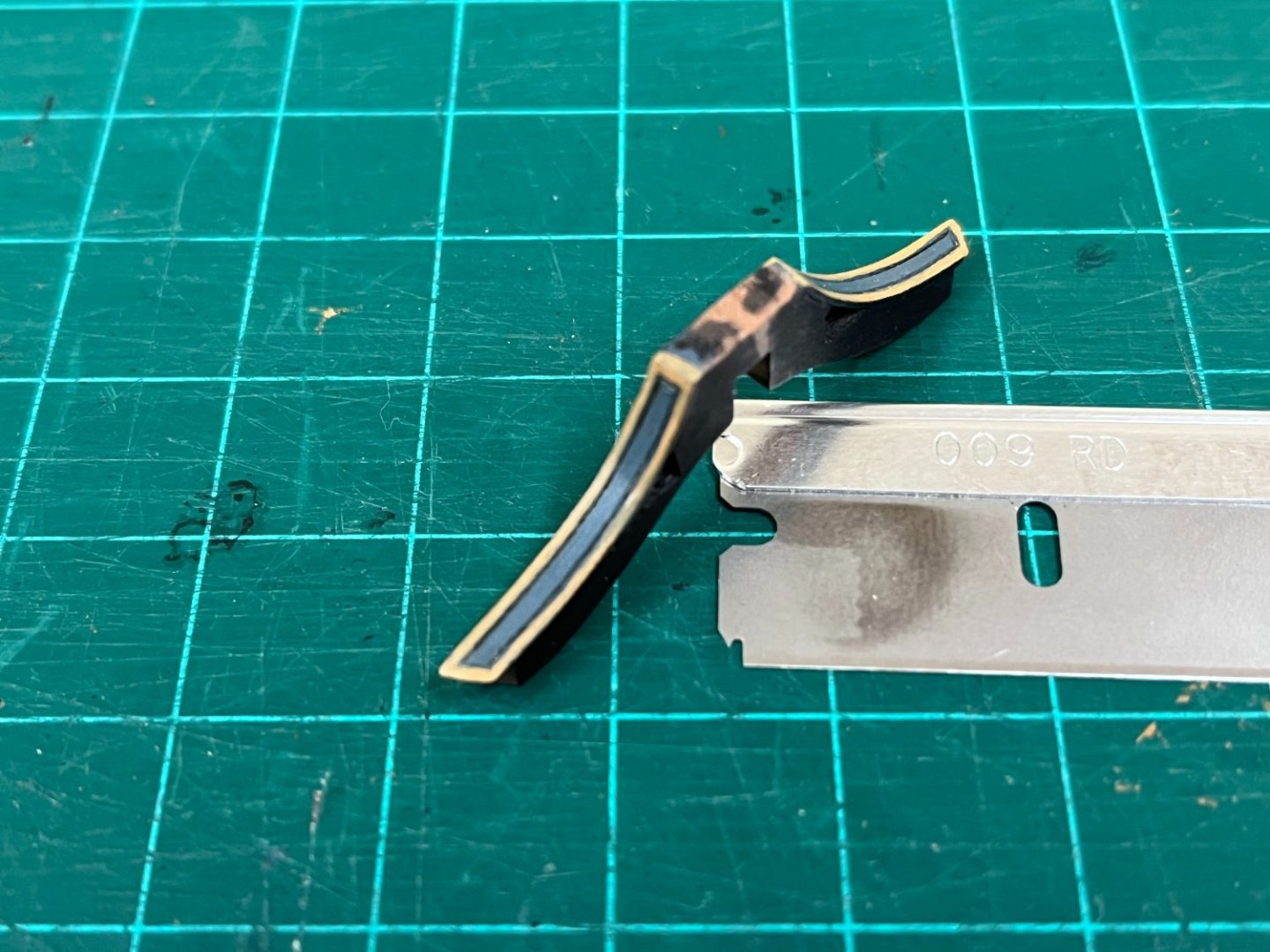
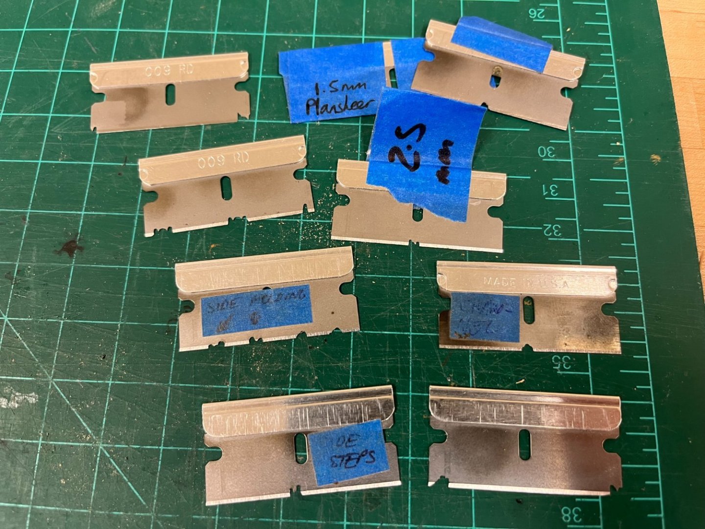
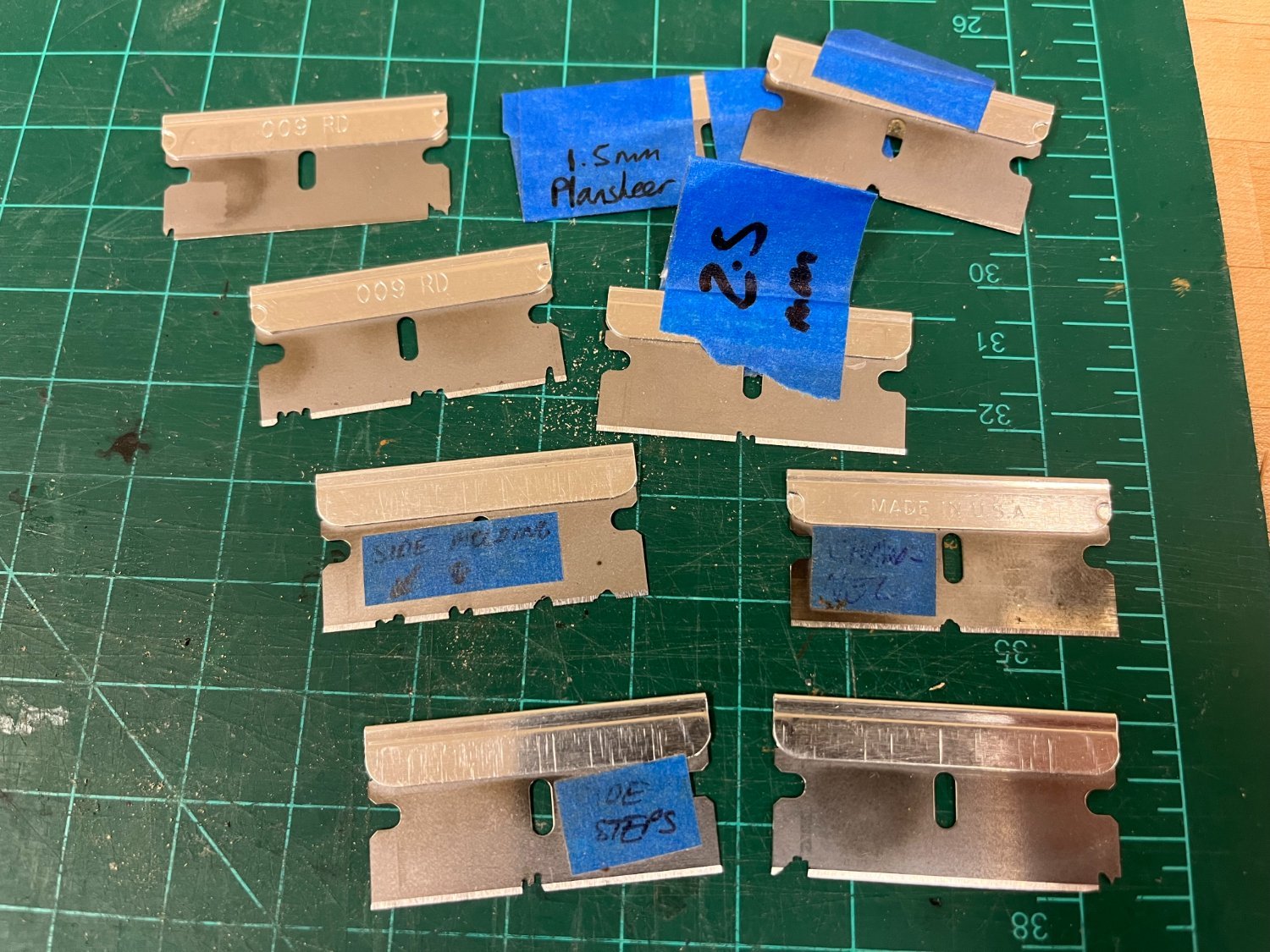
@DaveBaxt - the diamond cutting wheel is similar to this, easily cuts into the razor blades (545 Dremel | Tools | DigiKey ) with suitable eye protection! Sure there are many other similar items and prices from other retailers. The razor blades were bought in bulk...similar to these Multi Purpose Razor Blades (Pack of 100) (double-glazing-parts-spares.co.uk). Also, have provided a little more detail in update below...The wood used is either pear or castello box depending on what I have on hand, these woods are great for this. I would suggest you have nothing to lose, and much to gain by giving it a go....think you'll be pleasantly surprised at how simple it is with a little practice.
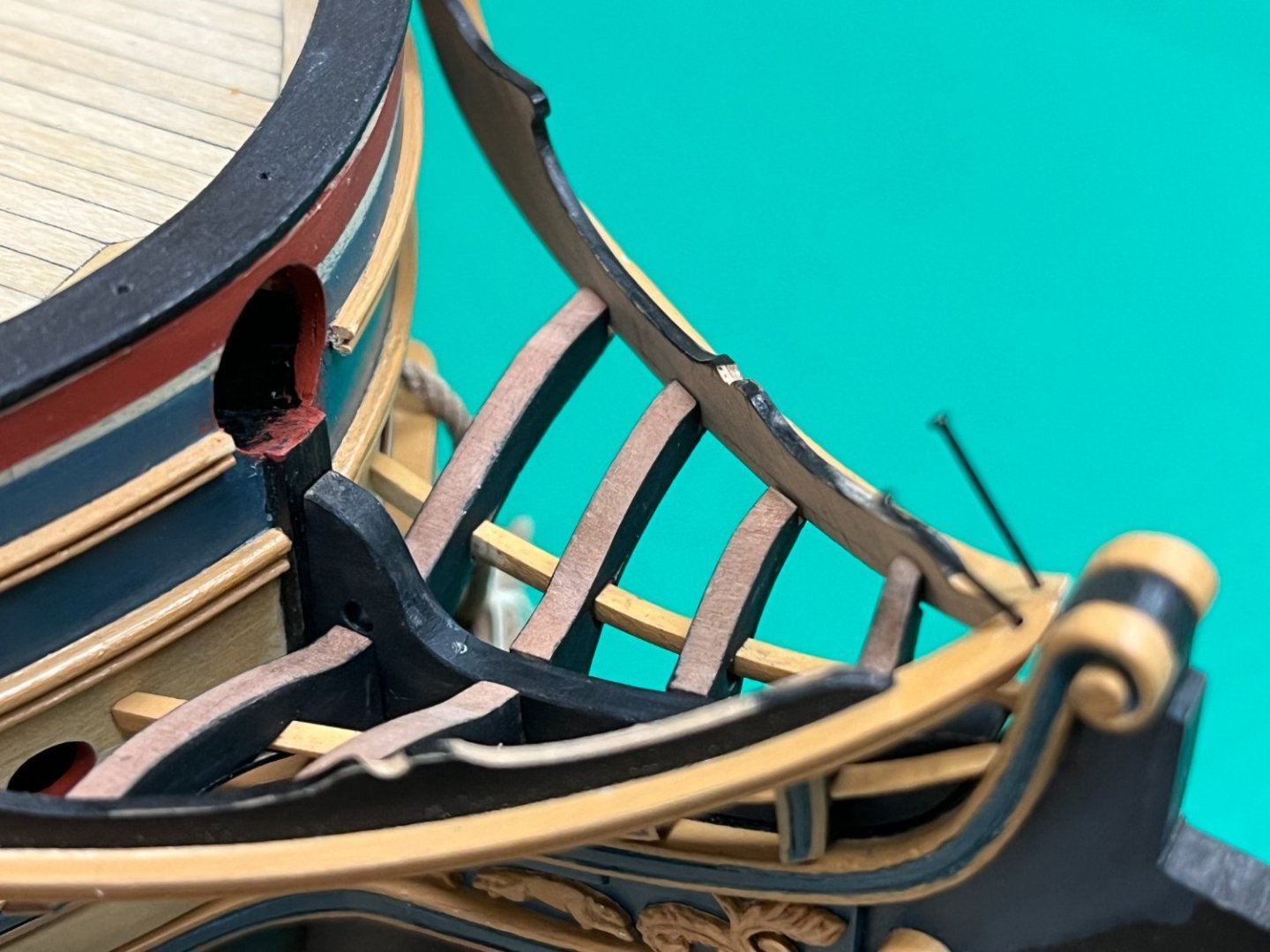
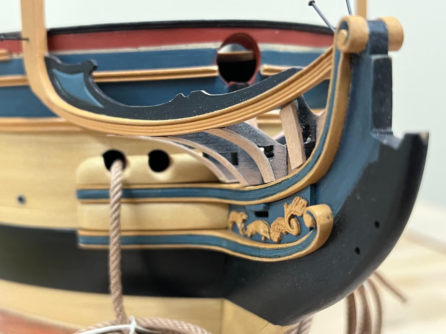
Much fiddling, fettling and fine tuning has been going on with the headworks, but this should bring me up to date. Think the back of this challenging task has been broken as I will likely be needing to spend much of any available time on unrelated projects.
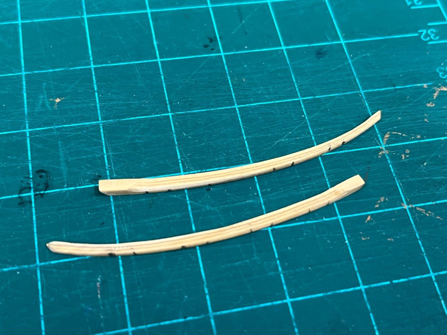
Once the shape of the head timbers had been finalized, the covering boards could be added. These are identified as being 1" in TFFM, so these were cut from 0.5mm pear sheet to approximately the correct dimension. TFFM suggests shaping these and attaching once the lower rail is in place, but am going to try and simplify because I'm not sure how successfully I'd be able to do this. Photos below show work very much in progress.


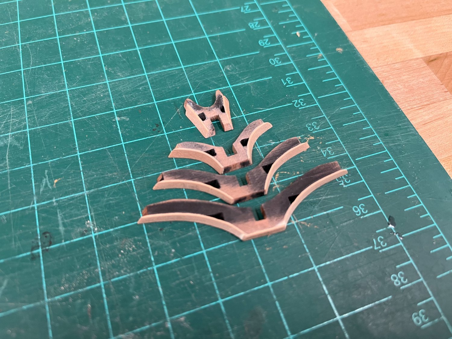
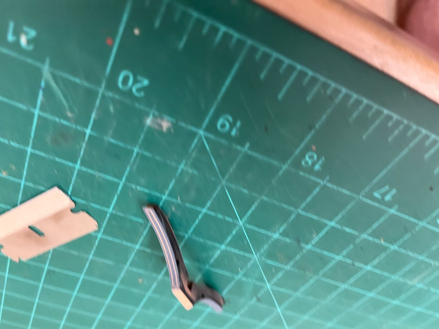
Once finalized, the time head timbers can be finished. A scraper was made specifically for the purpose to scribe the profile, with a long inner face than usual to act as a guide on both the fore and aft sides, and to account for the very different angle the face presents. A light coat of blue paint was applied to the outer face of the covering board to aid the eye in seeing the results of introducing the profile. Unfortunately, the only photo I had of this was of horrible quality, so apologies in advance but you get the idea. The scraper detail and a more final version is also shown below with paint applied.

The lower rail was profiled by temporarily attaching to some spare sheet and again a custom scraper. Finding one that followed approximately the desired profile and looked acceptable took quite a few attempts.
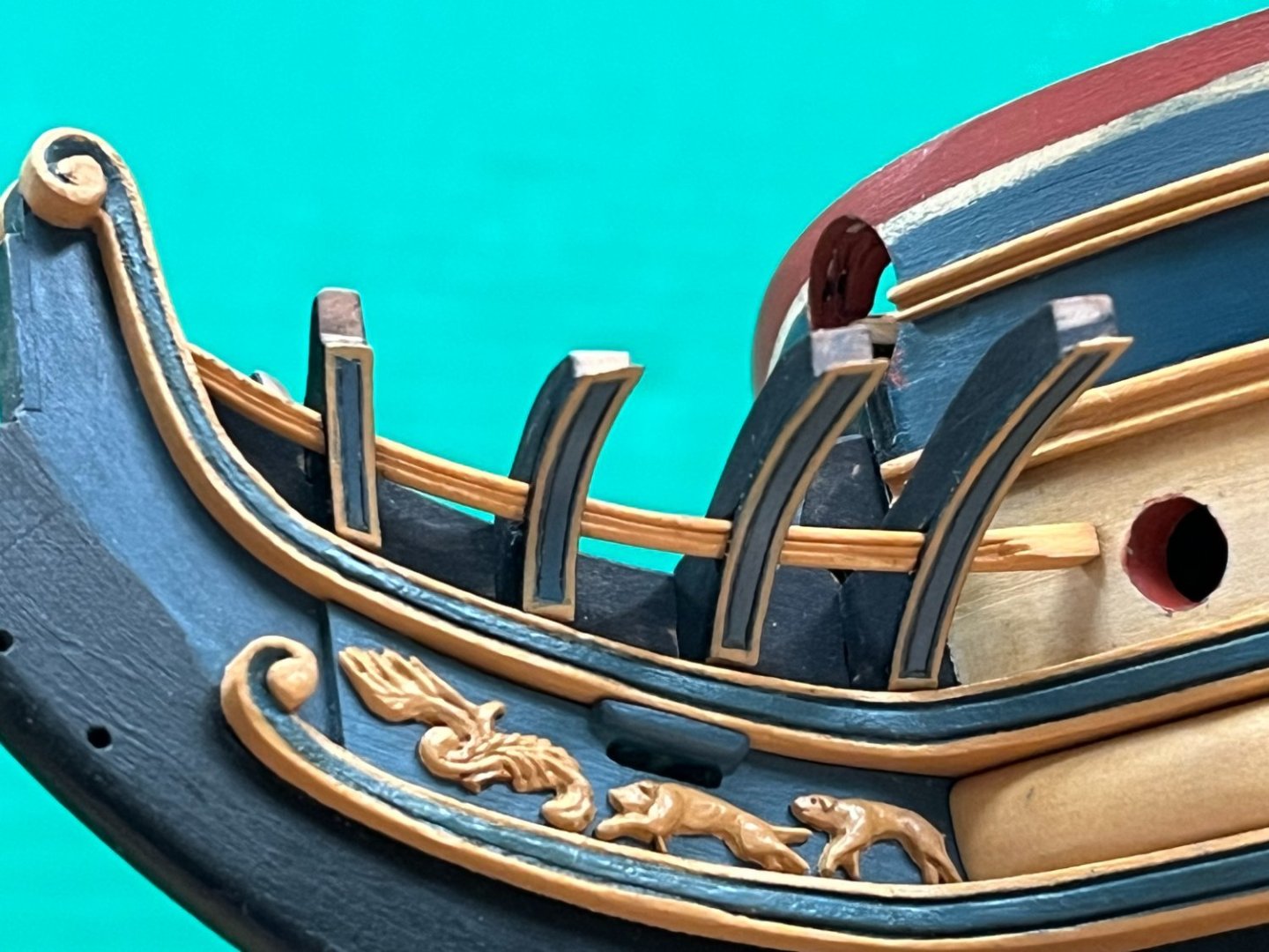
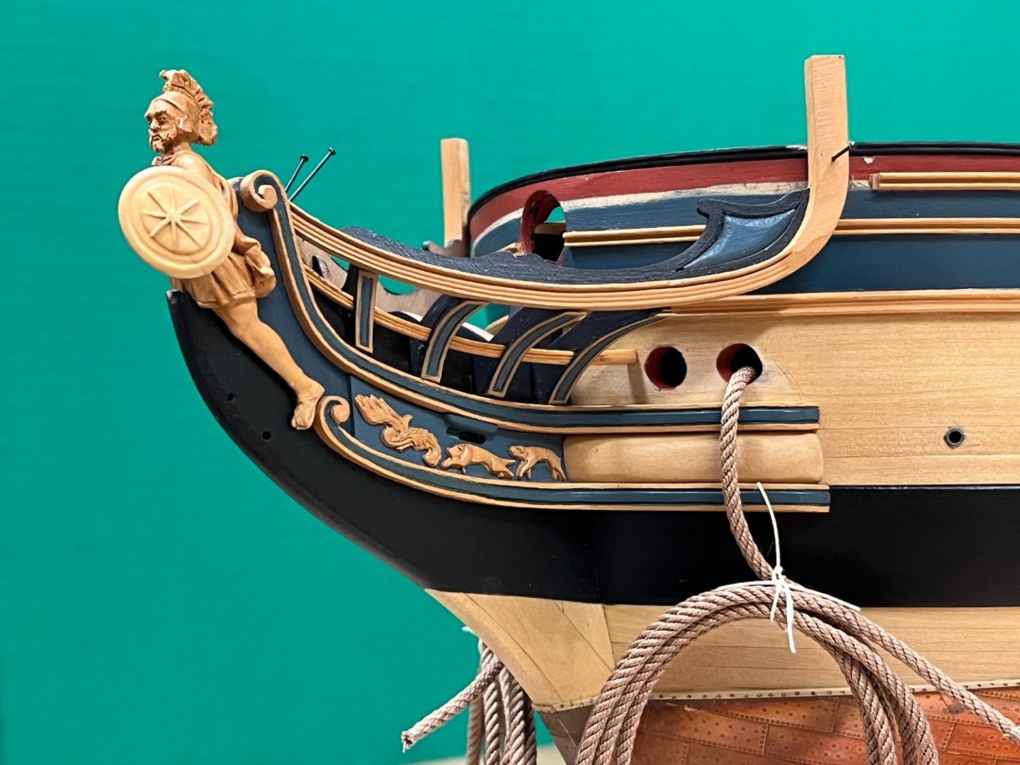
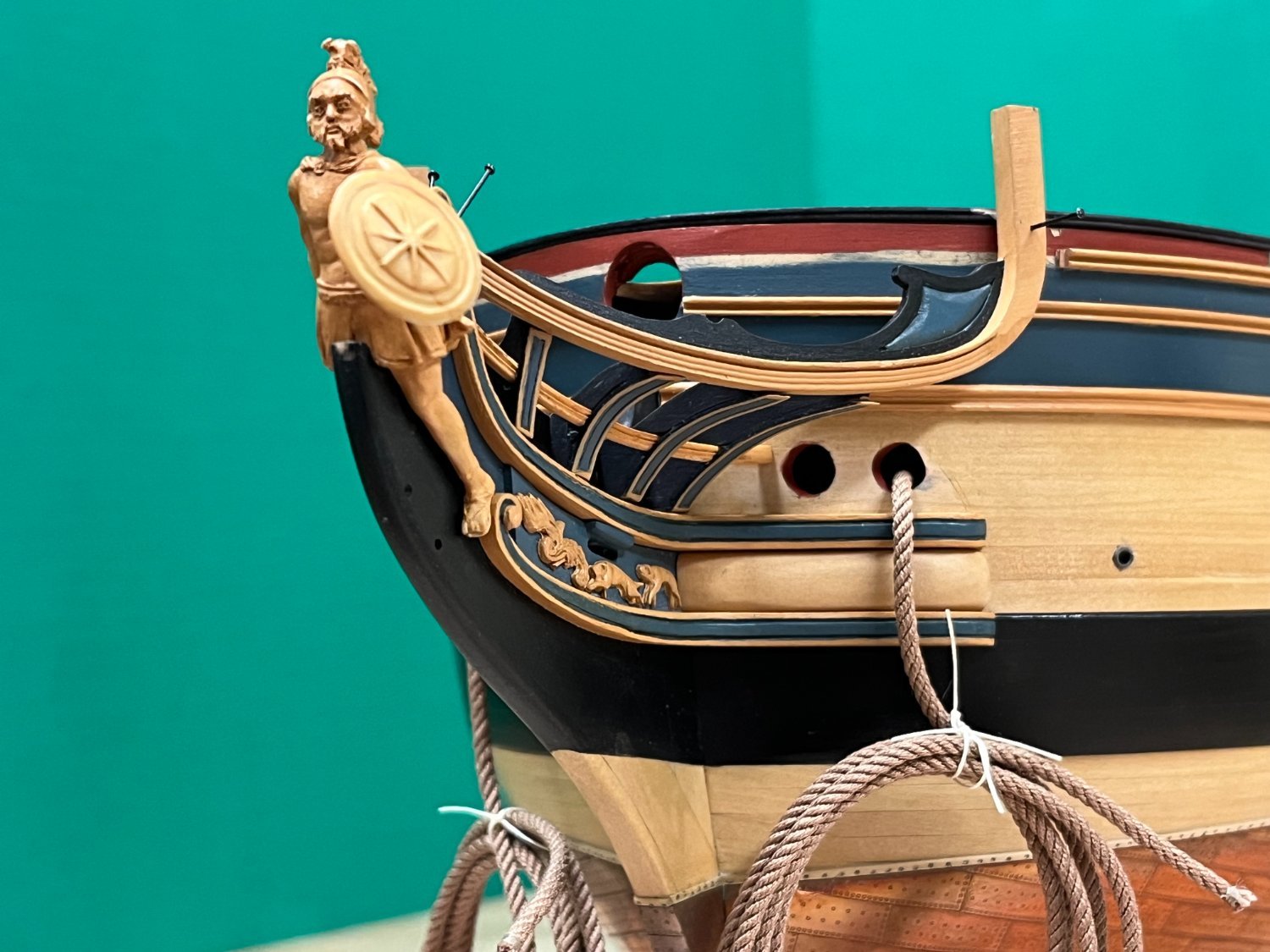
With all the key components really only requiring the some final finishing, it was time to cross fingers for another dry-fit - it gives confidence knowing that any additional tweaks can be easily addressed before glued to applied. The covering boards introduce a 'ledge' for the main rail to sit on, something that the simplified approach to shaping the head timbers did not include but seems prototypical. Some slight alignment issues apparent in the photos below should disappear when finally secured in place with glue. Next up is clearly some touch up after seeing these pictures on the PC!

-
Kevin, Hamilton, Mort - thanks for overly kind words and the likes. Hopefully have another progress update soon.
Dave - all the moldings are made from wood strip of various dimensions. I had ordered a long time ago some of the brass strips you reference but never used them, the brass just seemed very hard to work with, so I made the decision to make my own because it was a technique I wanted to get to grips with given the large number of molded profiles that may be needed. There are more professional techniques involving heating and cooling to harden, soften and harden again which probably allow a little more control, but I unashamedly just use razor blades and a cutting disc on my dremel. For me its a bit more art than science, and many reworks are sometimes needed because until you see the profile cut onto the wood, you don't know if it looks right or not. Getting comfortable with the result on a spare or offcut first is recommended!
-
-
-
Very well done Mort. she looks fantastic!
-
-
Siggi - the comments made above by others are all appropriate. The state of readiness of a ship could change in a very short time period, either bringing up cannons and makign up carriages stored in the hold, or moving a cannon lashed to the side to bring to bear in the gunport. The same for breaking down bulkheads. The "state of readiness" would be consistent with the threat situation....which is still true for warships today. There are many examples of models not necessarily reflecting a snapshot in time of contemporary practice, so none of that should get in your way.
-
Looking very nice Vane!
- Vane and HardeeHarHar
-
1
-
1
-
1 hour ago, DaveBaxt said:
I have just realized that the internal planking stops at bulhead 5 and 16, so they won,t need shaping. Phew
Hi Dave, think it is true that it will be very hard to see the interior bulwark when the foc's'l is in place so its definitely an 'optional extra' to plank further forward....however be aware you will need to build up the forward gunports if you don't plank there. I seem to recall that Ray went down that route on his Diana build if you have found his log.
-
25 minutes ago, Blue Ensign said:
Joining all planks at the central bulkhead is a practical approach, but the look of it offends my eye even tho’ this is only the first layer. We all have our foibles, I guess.
Not just you BE! Looking good.
- hollowneck, Blue Ensign and mtaylor
-
3
-
-
Have you tried looking at second hand book marketplaces? While not ideal, Abebooks for one does have one available as part of the set. You could always sell your duplicate volume 1.
- Keith Black and mtaylor
-
2
-
-
-
-
-
-
Looking great David!
- AJohnson, dunnock and SIDEWAYS SAM
-
3


HMS PEGASUS by giampieroricci - Scale 1:36 - Swan-Class Sloop from plans by David Antscherl & Greg Herbert
in - Build logs for subjects built 1751 - 1800
Posted
A really beautiful model, will definitely follow your progress Giampeiro.