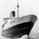
Jump to content

Recommended Posts

Hi Everybody

This is my first time posting on this site although I am not new to model building.

Several years ago while I was working nights I started a build of an RC model on a rather large scale of 1/35.

Earlier this year I came back to it to finish it and found several major structural problems had developed due to the heat and humidity in my country, I could hve tried to fix what I had done but opted to start again and this time instead of Plank on frame I have gone with bread and butter for lower hull and plywood for the rest.

Another reason for the redo is I recently purchased Stepcraft 840 CNC so will be able to translate the design into the model with much much greater accuracy.

This model was initially on a build blog on another site but this has stopped being fruitful and after all the whole purpose to build blogs is to give and receive help and tips .

I am nearly 50 years old and been modelling ships all my life though not this big, my father before me also built models on commission to shipping companies on 1/8 scale

My background is in both furniture building for 16 years nand 20 years of 3d modelling and ship design, my main software being Rhino ,Modo and Maya.

Over the recent weeks I have been building the framing and shell structure in 3d and nesting ,the parts on sheets ready to be cut on the CNC.

The approach of this structure is 6.5mm 5 ply framework with a 2mm 5 ply covering to box it all out, this has all the openings cut in etc 1.5mm oversize and then the whole is plated properly with .5mm ply which also has all openings and doors etc cut into it as well as curtain plates etc, this models disp in water is 193kg and runs 2 24 volt, 450w motors powering 2 custom made 100mm props from Simon Higgins in the UK, he is also currently building 2 working lateral thrusters as they are beyond my metalwork ability.

This ship was one of the most beautiful vessels built on the Clyde in the 60's.

I have many links to this ship in my past and have a massive collection of plans of this ship 200 original plans and hundreds of photos.

No part of ship is not photographed and plans for all of it are accounted for.

I will give a few images of the first attempt so people can see the size and work that went into the model first time and will follow up with the hull as it is now and some shots of the cad model

623234.jpg


641087.jpg


651680.jpg


623235.jpg

650562.jpg

651038.jpg

651037.jpg

622813.jpg

640451.jpg

640453.jpg

682251.jpg

665864.jpg

676288.jpg

Edited by Richard Dunn
Link to comment
Share on other sites

So that was the first go at the hull which I was forced to abandon due to structural issues in the glassing of the hull.
Below is the new   hull and shots showing how it was planned and broken into shorter sections per layer with stepped bulkhead to keep alignment accurate athwartships.

The tug is an empire class tug (Tapuhi) as a service model to the main

894491.jpg

894492.jpg

894493.jpg

894651.jpg

894652.jpg

894795.jpg

895128.jpg

894653.jpg

894657.jpg

894654.jpg

Link to comment
Share on other sites

You will notice above the substantial Aluminium beams on the building board.

Here are some images of the cad model a few hours away from being ready to cut the parts.

Assembly should be fairly quick as it all  slots together, yes I have done fit tests and yes it does go together.

The first image shows the main longitudinal girders that help tie it all together and the first 3 images are with the superstructure lid off, the 4th shows it on.

profile main girder.jpg

main frames.jpg

2.1mm covering.jpg

Lid in place.jpg

stern plating.jpg

bow_plates.jpg

Cutting files.jpg

Link to comment
Share on other sites

This part of the process has taken many weeks to accomplish, so that the model is built in a way that locates every part accurately into others with tabs or half joints, also to ensure that parts go together so that they don't interfere with access to hull interior, I also had to be very careful not to build in problems where parts could not be assembled as they had to be slid or forced into 2 directions at once so assembly order became VERY important.

There are 4 interior spaces that need to be fitted out as well and these had to be designed so they could be done but still have access to hull.

Edited by Richard Dunn
Link to comment
Share on other sites

If I remember correctly, wasn't this ship caught in some hurricane like around Fiji and either ran aground or strike a reef? Don't remember the full story, but she was listing pretty badly after the hurricane. She was talked about in a book that my dad has about a number of ships in nautical history.


Brian :)

Link to comment
Share on other sites

Hi Brian
Sort of correct, she was caught in a double Cyclone in Wellington New Zealand and foundered with loss of 51 lives.
Here is an archived website about it here.

https://ndhadeliver.natlib.govt.nz/webarchive/wayback/20160417074849/http:/www.thewahine.co.nz/Time.html

Link to comment
Share on other sites

Looks to be a fascinating project, Richard.   And a big one.   If you would, open an intro in our new member introduction area.  It's basically a "meet and greet" area.  https://modelshipworld.com/forum/3-new-member-introductions/

Mark
"The shipwright is slow, but the wood is patient." - me

Current Build:                                                                                             
Past Builds:
 La Belle Poule 1765 - French Frigate from ANCRE plans - ON HOLD           Triton Cross-Section   

 NRG Hallf Hull Planking Kit                                                                            HMS Sphinx 1775 - Vanguard Models - 1:64               


Non-Ship Model:                                                                                         On hold, maybe forever:           

CH-53 Sikorsky - 1:48 - Revell - Completed                                                   Licorne - 1755 from Hahn Plans (Scratch) Version 2.0 (Abandoned)         


Link to comment
Share on other sites

Hello Richard, and a warm welcome to the forum from down in Sydney.


A beautiful and a tragic ship!  That looks a very fine model you're building of her.


A mate of mine was master of the Lytellton ocean rescue tug at the time of the Wahine disaster and they were on standby to sail up to Wellington to assist if required.  I remember him telling me that his wife was begging him not to go because of the severity of the weather and he saying that he told her that they were a rescue tug and their reason for existence was to rescue ships and people.  He also said that they were actually very relieved when they were told they weren't needed - he said, "I'm not sure we would have got as far as Wellington in those seas."


John


John

Link to comment
Share on other sites

Hi Richard,

An interesting build!!


The only other models of the Wahine that I can remember, are in the Maritime Museum in Wellington.


Your post has bought back memories of that day, I was eight and lived in the coastal suburb of Eastbourne, Wellington.

So, there was no warning of the impending cyclone, (Giselle), I guess forecasting has progressed....


My father had driven to work, (In the city), on the morning and by the time for school, the wind had really ramped up.

By the time we had got to school, we were informed it was closed due to blown-out windows.

Got a lift home from one of my friends mother.  On the drive home, (About a mile.), I remember seeing huge waves breaking over the sea wall.


News reports came in regarding Wahine and other damage around.


Remembering hunkering down at home and 4WD vehicles heading out towards the Pencarrow Coast to assist in rescues.

(From memory, most loss of life was around the eastern coast, fairly rugged with unforgiving rocks.) 


To cut a long story short, the ship had founded on Barrets Reef at the entrance to the harbor, it was there for many months, on its side, while the salvage crews cut her up.


A day after the storm, I was lucky enough to find a five dollar note stuck in the hedge outside my parents house, five dollars bought a kings ransom in stuff back then!! (I did think some years later that this might have come from some poor soul on the ship.)


Wahine was replaced on the Lyttelton to Wellington run by the Rangatira for a few years after the tragedy.

(Wahinie - Beautiful Woman)


I shall follow you build with interest!!


Cheers....HOF. (Harry)


Edited by hof00

Completed Builds:


A/L Bluenose II

A/L Mare Nostrum

Sergal/Mantua Cutty Sark

A/L Pen Duick

A/L Fulgaro

Amati/Partworks 1/200 Bismarck

A/L Sanson

Link to comment
Share on other sites

Hi John and Harry
Yes it is certainly one of those "where was I when" moments, I was only born in 71 so not even alive although I am from Wellington, but half my family worked for the Union Steamship company and the Naval Architect who designed her was a friend of the family so it all became too much to ignore, I fell in love with the ship because of her looks, not because of her fate although in saying that a good deal of the reference I have is from the wreck including 4 hours of video documenting her scrapping as well as just her short  2 year  life. John I never knew that was planned, luckily it blew out as fast as it hit, by 11.00am it was just a regular Wellington Storm but yes it was a very significant moment for design to, many Ro Ro rules and standards were changed because of her sinking and ways of stopping free surface water effect.
Harry you are correct, not one person died on the ship, they died sadly on the rocks in the monstrous sea breaking on the shore or a couple of exhaustion after floating around for so long waiting to be rescued.
her looks continue to inspire artists and modellers, I frequently get requests  for sets of plans and photos for things ranging from paintings to models, even from people with no ties to NZ, quite amazing really.


Wahine Aerial.jpg

Edited by Richard Dunn
Link to comment
Share on other sites

It is a real pleasure to see another member that takes  time doing research and paying close attention to details.    Your scale is quite large so a fun build log to follow.  Thank you for sharing your first go around as well as your new B&B build.

Allan

PLEASE take 30 SECONDS and sign up for the epic Nelson/Trafalgar project if you would like to see it made into a TV series.   Click on http://trafalgar.tv   There is no cost other than the 30 seconds of your time.  THANK YOU


Link to comment
Share on other sites

Thanks Yves
Yes I suppose I am using all techniques , to be honest once the CnC is all cut sanded and removed from sheet it should take very little time to assemble and look like a ship again, the hardest part for me will be deciding when to paint each section, have had automotive acrylic paints made to the BS381c standard and will be airbrushing, though the decks which have a lot of oxidisation and touchups will have to be done with Tamiya and done by hand along with weathering techniques, the green decks always look grubby.

The hull plates will be laid in .5mm 3 ply  with grain vertical and the edge very lightly arissed or bevelled, the weld bead then gets glued into the slight depression left and the bead rolled with a serrated roller to give effect of weld, the tin canning effect I want to get but understate will be sanded into the high build primer by sanding between frames with finger taking advantage of the un uniform nature it will give, at least that's the theory at this stage, I have not actually tried it yet, the other is to make a rubber screed with the tin canning shaped cut in and hard filler applied to each plate once on hull though this will take a lot longer, but hull an ship will be fully tin canned as this ship had it a lot and was noticeable.

I am wondering if making a scale paint roller would yield good results for deck paint to get the pattern you get with uneven coverage.

The deck is a colour called forest green, its a dark almost Brunswick green but quickly goes chalky and a pale verdigris colour so was always being touched up. decks were done in a compound called Semprene which was rubber system about 1 1/2 inch thick applied to steel decks, I will be making this from 1mm ply prefinished off ship and glued into place after other paint is done on waterways and deck bars etc.

Below you can see the effect, both those colours are the same paint but the bridge top is faded version, image has a cast, yes I know it looks blue but its not.
the second image has no cast and is correct colours as far as photos can be

Deck from Funnel.jpg

deck.jpg

Edited by Richard Dunn
Link to comment
Share on other sites

I have a question and would like to know suggestions on ways to make a very delicate and troublesome fitting.
Grills
The big metal finely spaced grills used into engine spaces.
I need to make a lot of these with an average size of about 55mm high by anything from 12mm to 60mm wide, they are all fitted into  a frame which has radiused corners, does anybody have suggestions other than brass shim and solder?

I suspect the blades are bent at a 90 degree angle which would make jigging harder, or easier depending how you look at it.

Image below of typical fitting

Measurement from deck to deck is 69.6mm to give idea of size
 

Grills.JPG

Grill.jpg

Edited by Richard Dunn
grammer
Link to comment
Share on other sites

Yeah had a look but i need these to be 6mm deep ish and .5mm apart looks like a jig is in order and soldering it out of brass shim, ,I will make the part from photo etch and then solder, that way...oh I just had an epiphany, frame bent from one strip and blades have 2 little tabs each end that fit into holes in frame at an angle, then jig to hold it all square and solder.

CNC sheets count is now at 12 sheets, another 4 done today

Edited by Richard Dunn
Link to comment
Share on other sites

This image shows the Smoke room, one of the passenger areas that needs to be fitted out due to large windows, note the green area which is removable floor to access the spaces under, the join in the floor falls between tables and chairs.
The engine casing will support the ceiling which is also part of the removable assembly that lifts out. I have added a photo of the space so you can get a feel for it.

Smoke Room removable.jpg

2006;15_6_325_8.jpg

2006;15_6_325_3.jpg

Edited by Richard Dunn
Link to comment
Share on other sites

Here is a couple of parts to show the accuracy of the joints and how it was prepared in 3d to be transferred to 2d and on to CNC

parts.JPG.def022f1a5df91c0cb0e6b9a8eceb669.JPG

I then cut on the CNC

433885931_DSCN8649copy.thumb.jpg.4eb2f48d8c0d7fe142a4d8116eb7bc13.jpg

And after sanding the sheet and cleaning up tabs we get parts that fit like this.

1740569020_DSCN8645copy.thumb.jpg.7f56e538d8d416a88d2e40082ebdef89.jpg117137620_DSCN8646copy.thumb.jpg.bd390fca4d69aef67b64ffb340682d21.jpg386643333_DSCN8647copy.thumb.jpg.a3cc49adbd18d5870e91d5f791ed020a.jpg

Notice the corners are "dogboned" to clear the radius from the corners of the holes, the pen work is also done on CNC with a pen attachment so frame lines are perfect

Link to comment
Share on other sites

Just going to post my "instruction manual" pages here in case its of interest while I get into my head the assembly order 
Step 1 - foundation plates assembled and glued to top of bread and butter lower hull.


Step_01_Foundation_Plates.jpg

Edited by Richard Dunn
Link to comment
Share on other sites

Join the conversation

You can post now and register later. If you have an account, sign in now to post with your account.

Guest
Reply to this topic...

×   Pasted as rich text.   Paste as plain text instead

  Only 75 emoji are allowed.

×   Your link has been automatically embedded.   Display as a link instead

×   Your previous content has been restored.   Clear editor

×   You cannot paste images directly. Upload or insert images from URL.

  • Recently Browsing   0 members

    • No registered users viewing this page.
×
×
  • Create New...