


James H
-
Posts
5,963 -
Joined
-
Last visited
Content Type
Profiles
Forums
Gallery
Events
Posts posted by James H
-
-
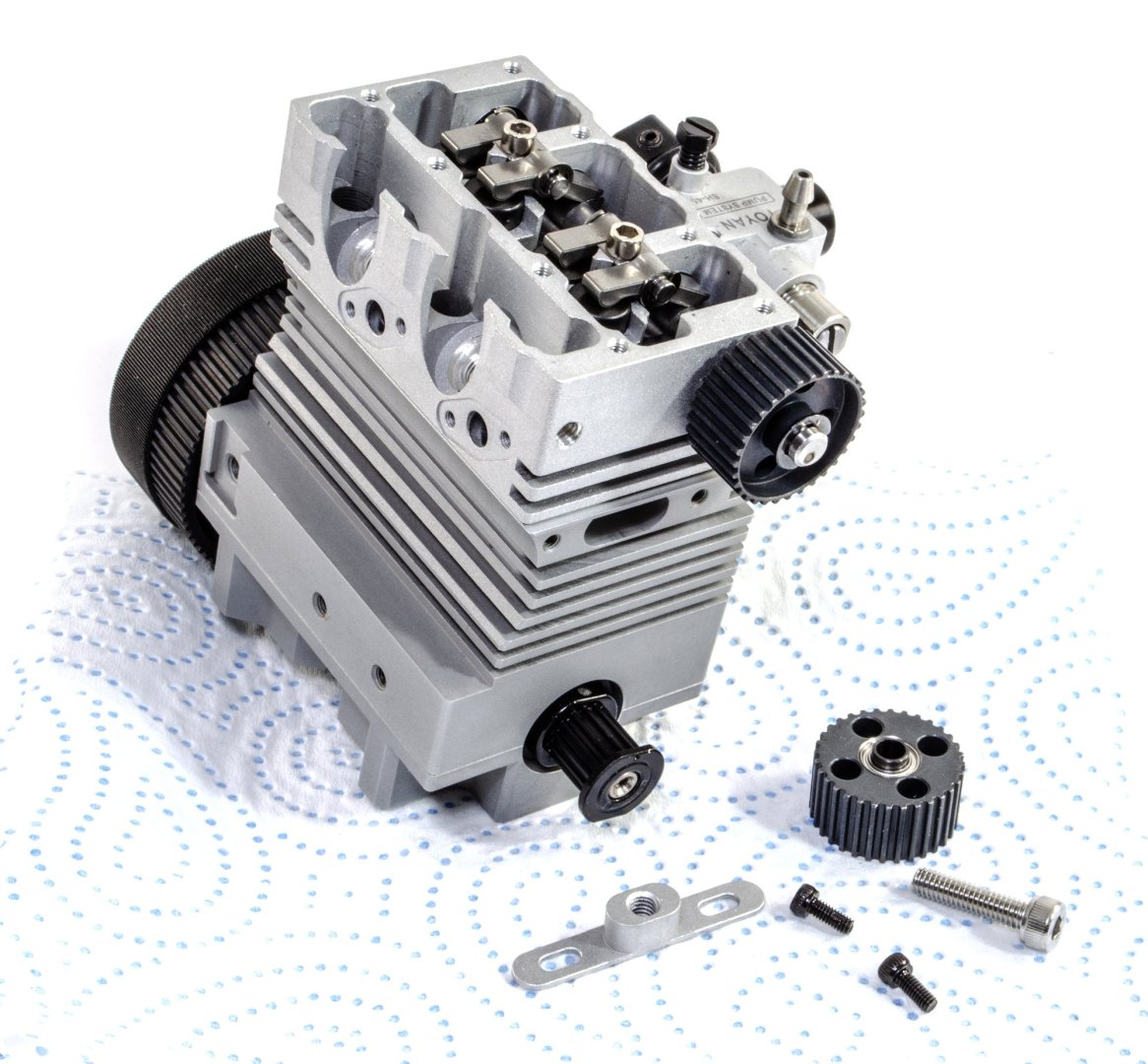
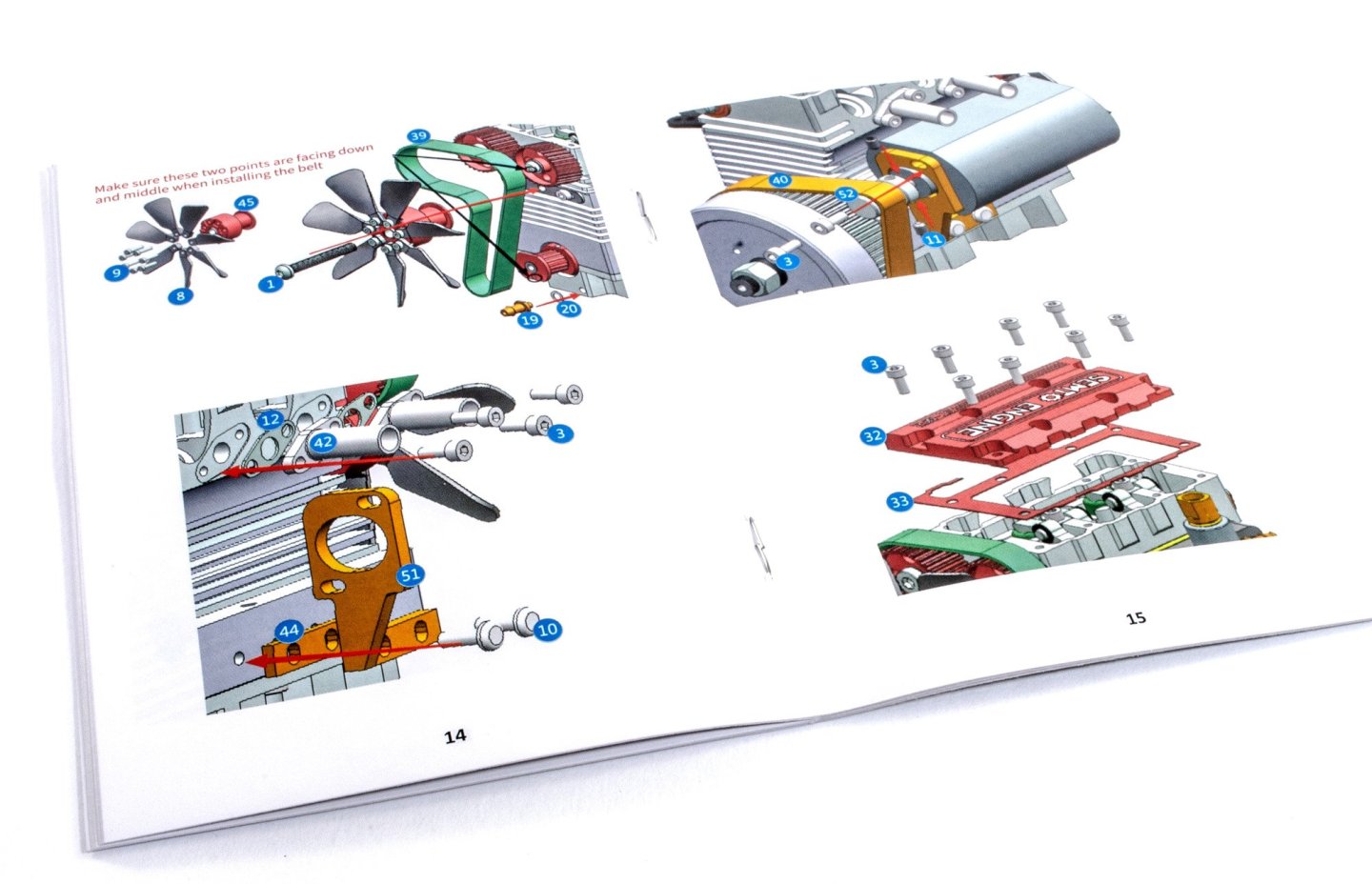
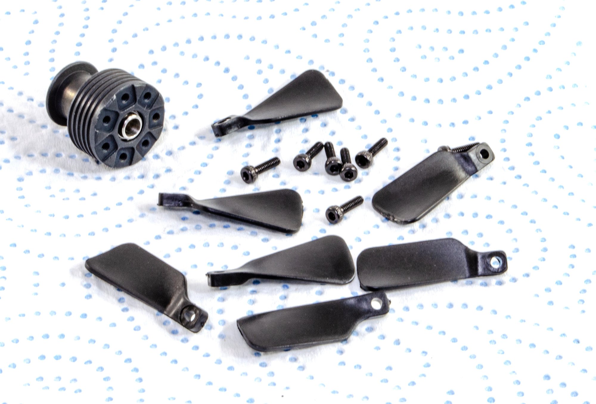
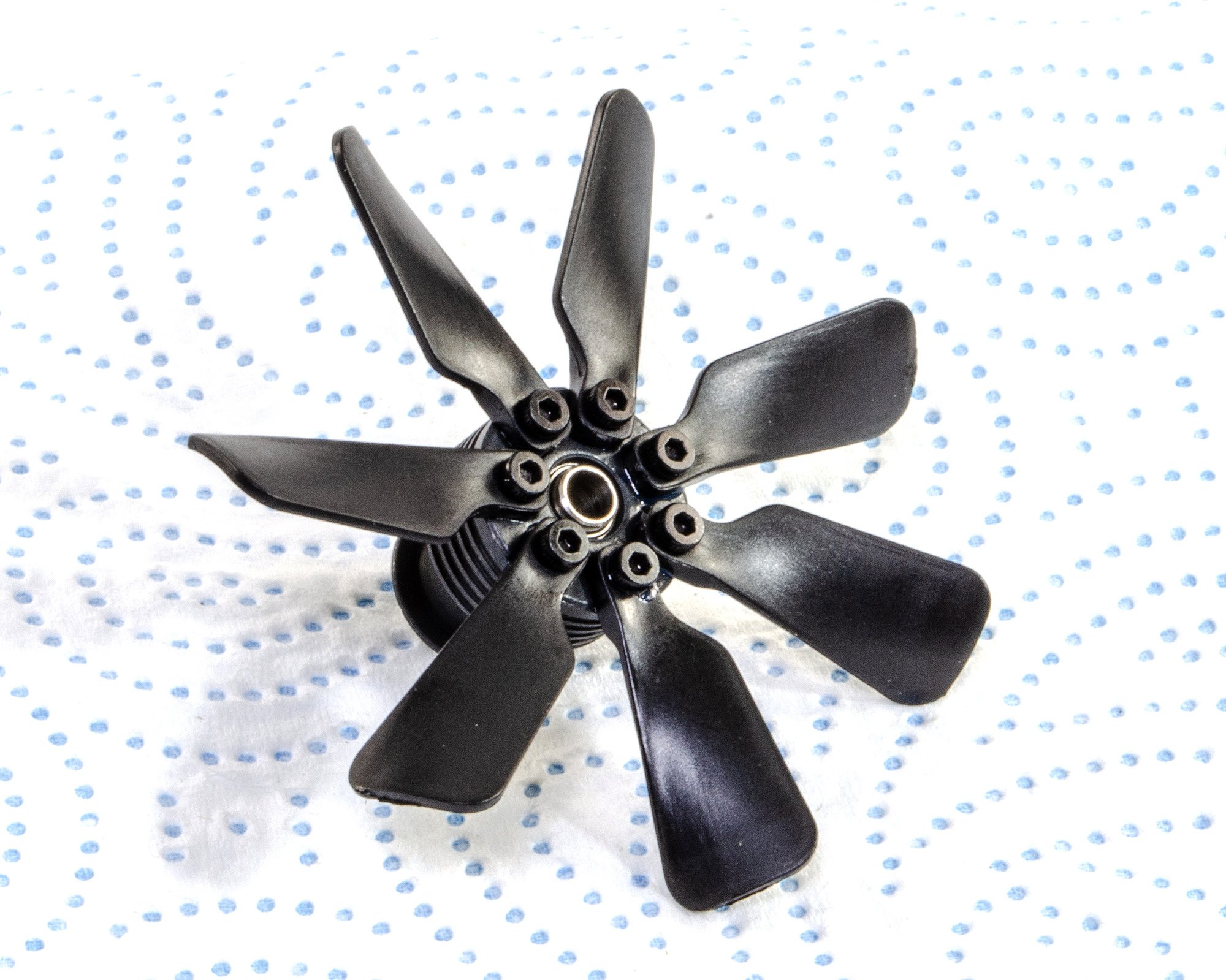
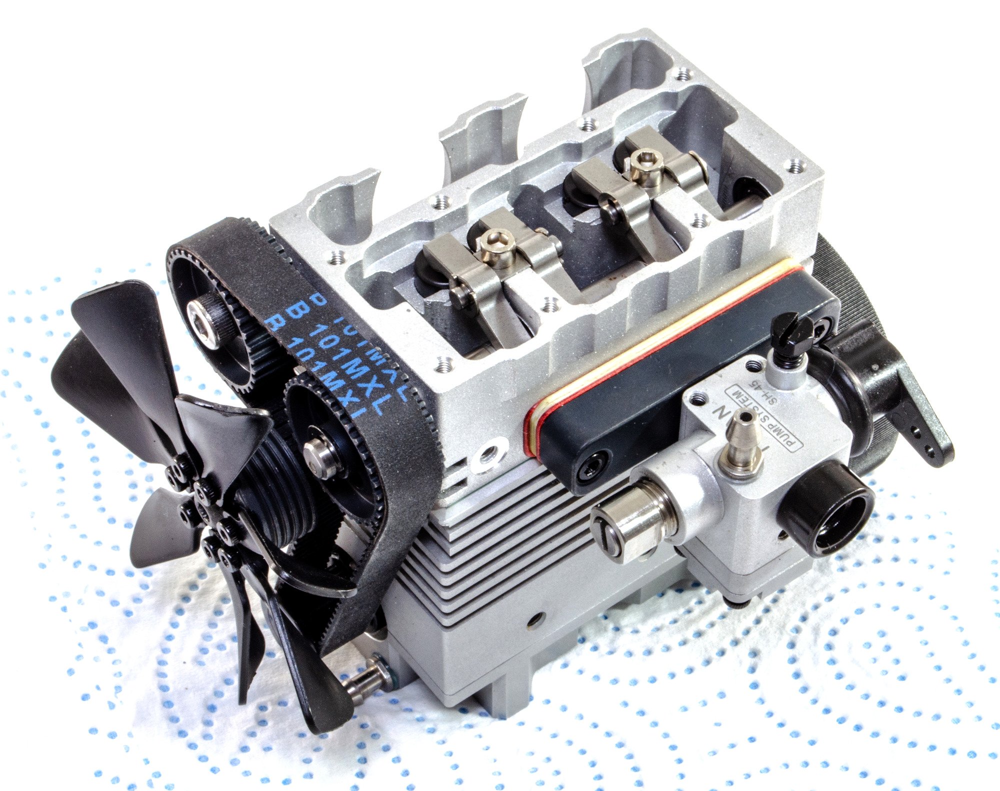
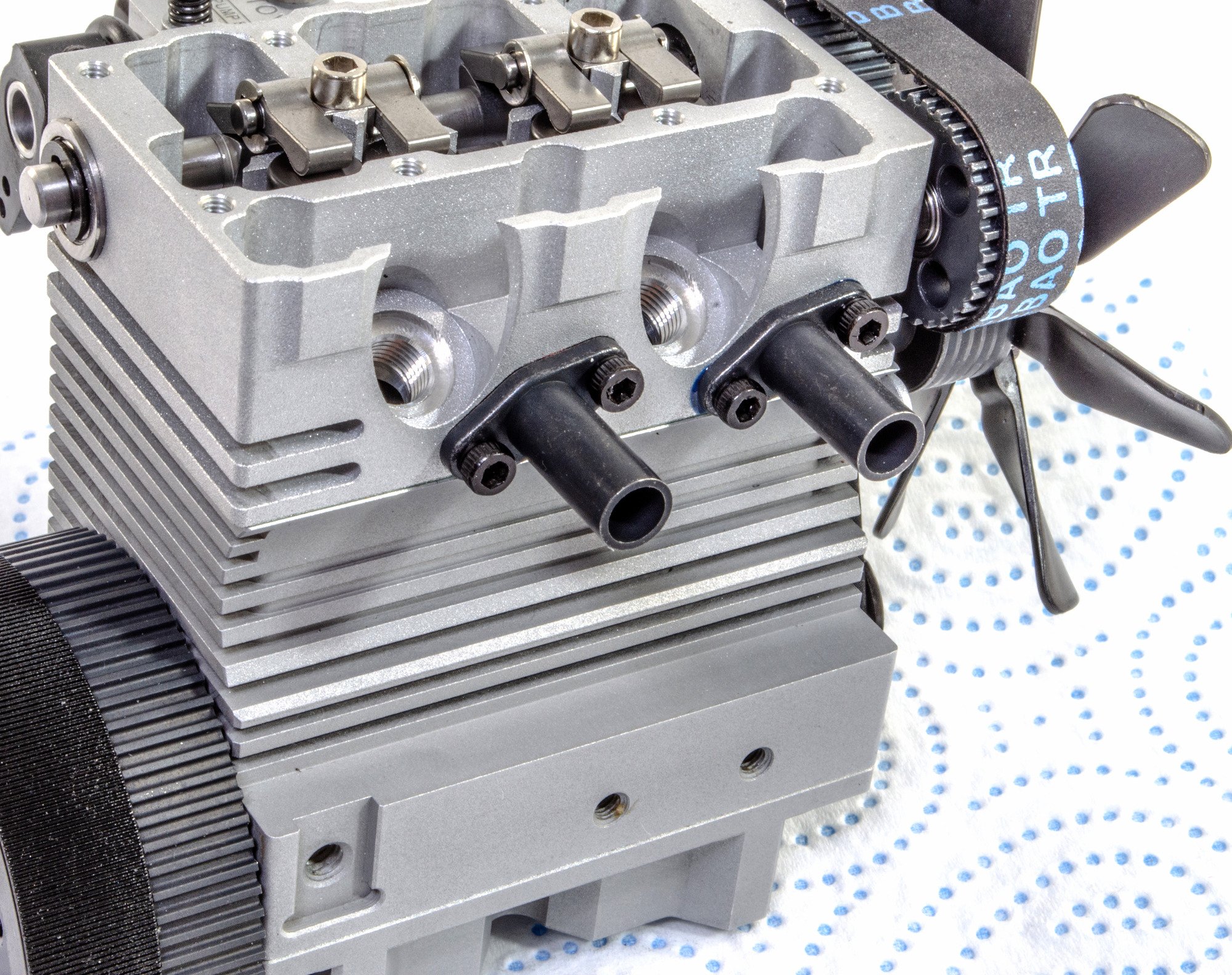
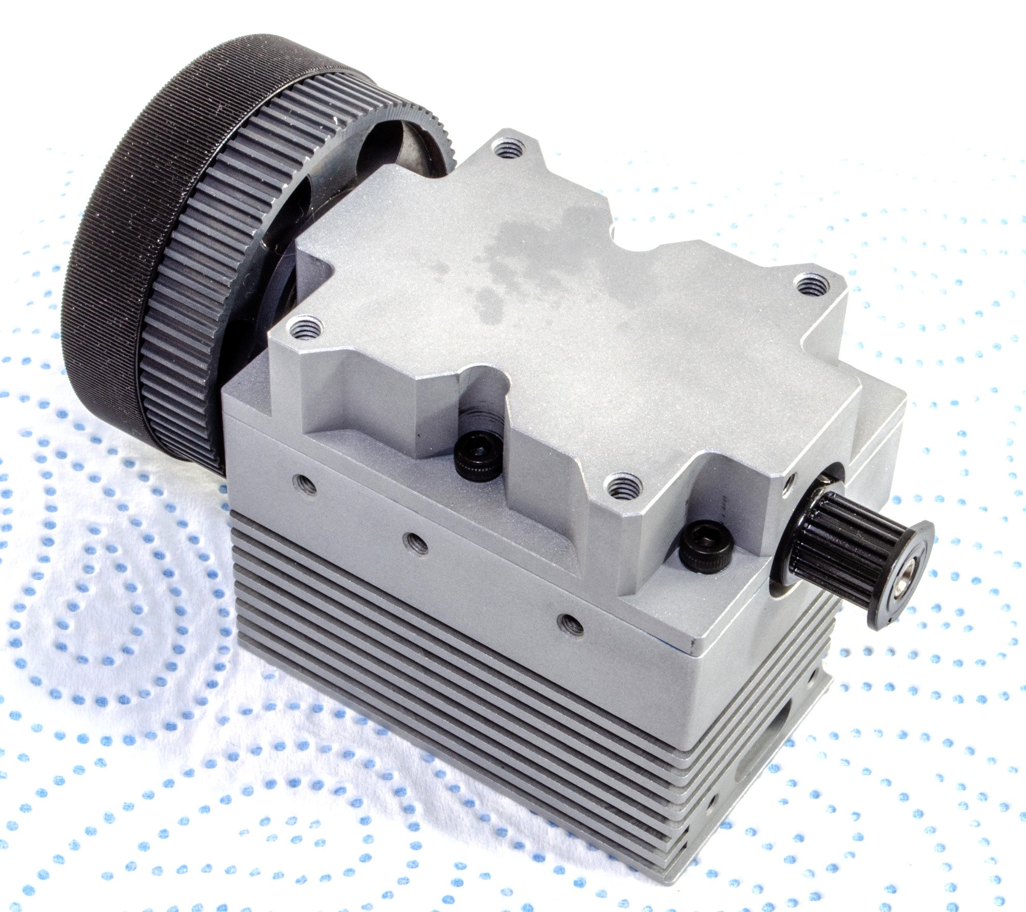
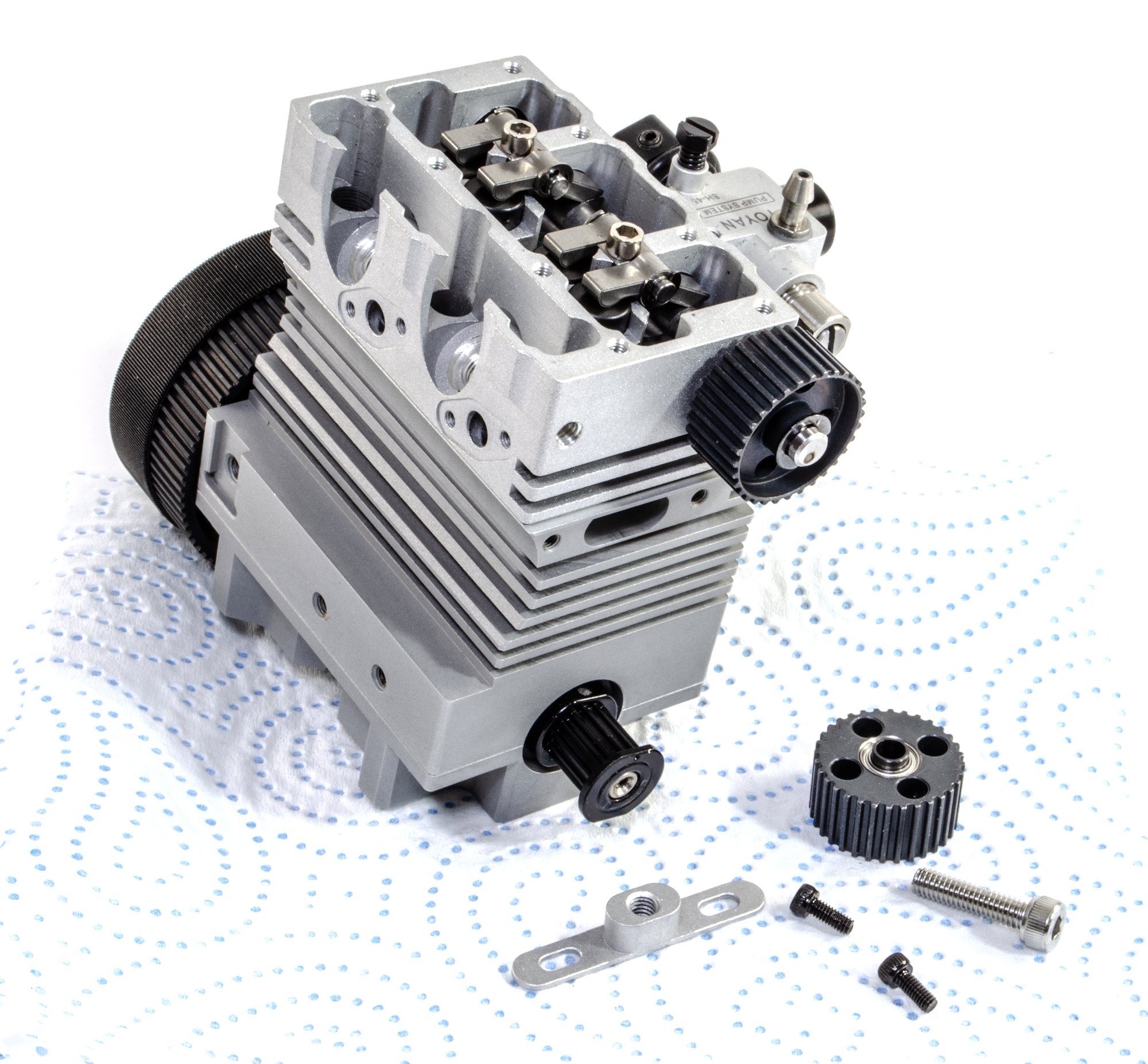
This engine is air cooled, and watching some videos, this is actually quite effective. Before the fan can be installed, it needs to be assembled. This is nice and simple, and like all bolts on this kit, I use some thread-lock to ensure nothing shakes to pieces when it eventually runs.
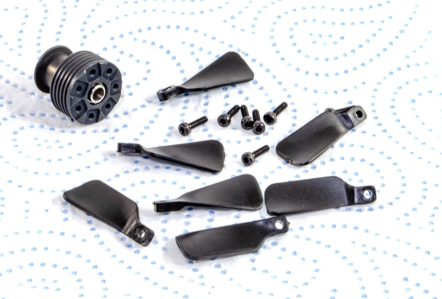

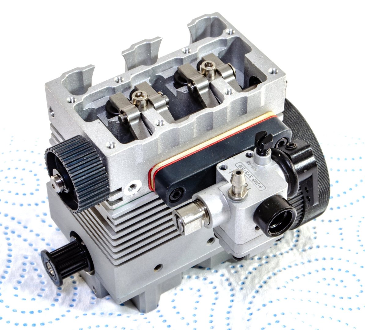
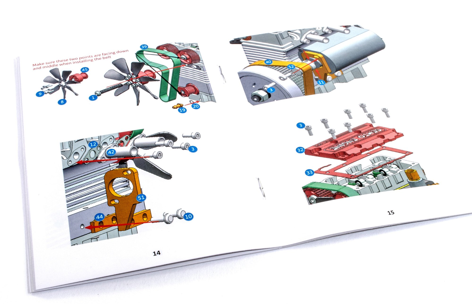
The fan is now fitted, along with the drive belt. With the belt installed, the adjuster is then tensioned fully and tightened.
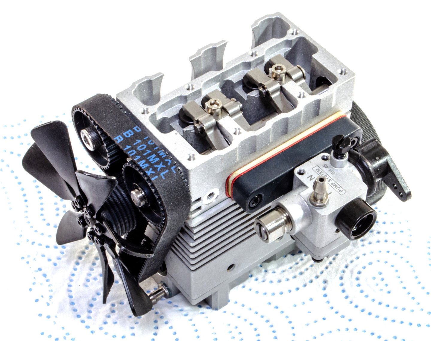
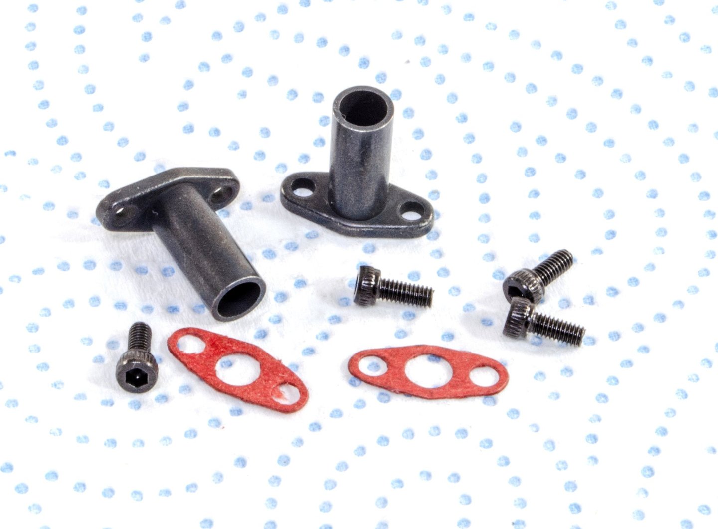
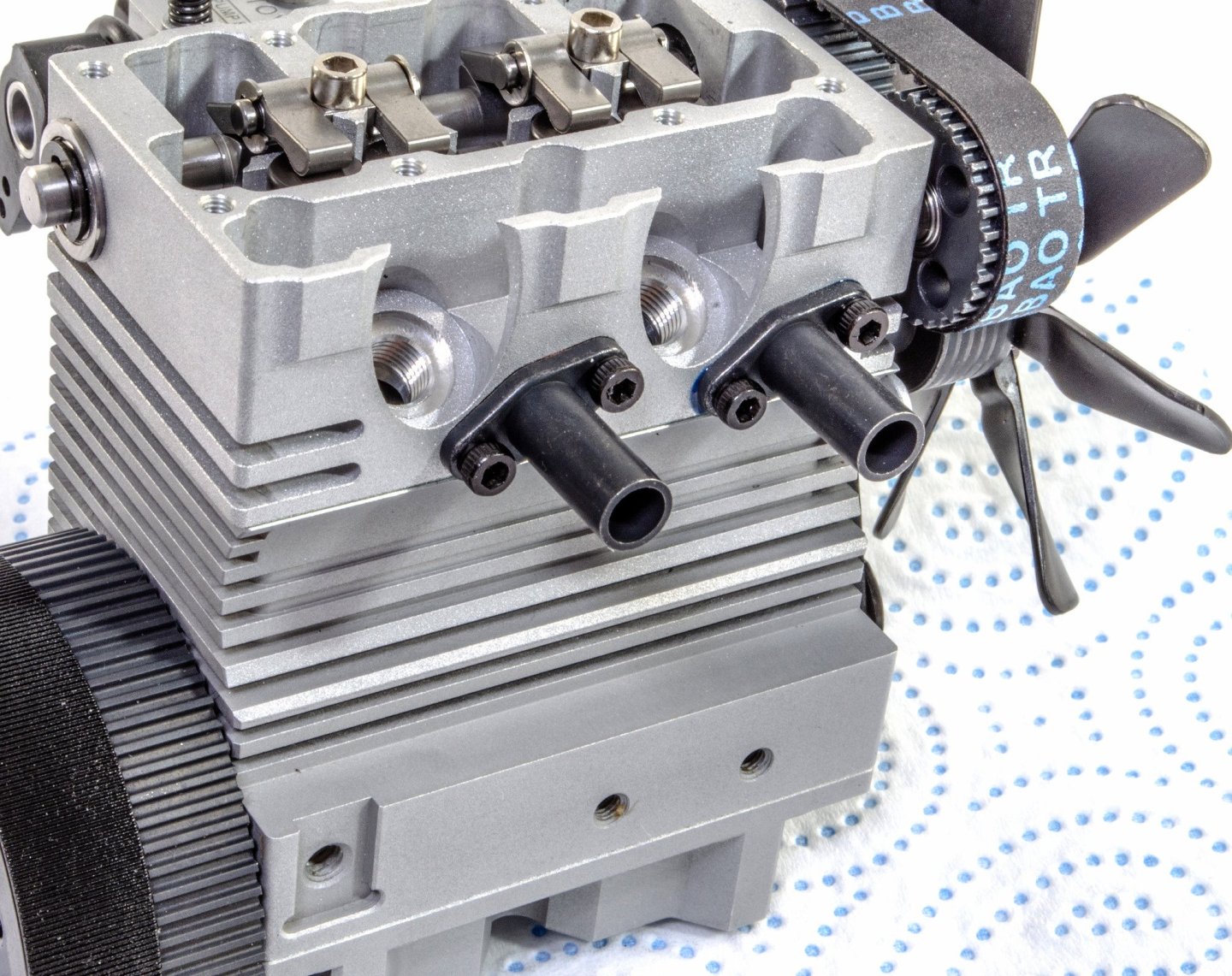
The exhaust ports are now fitted to the cylinder head, with gaskets to seal them.
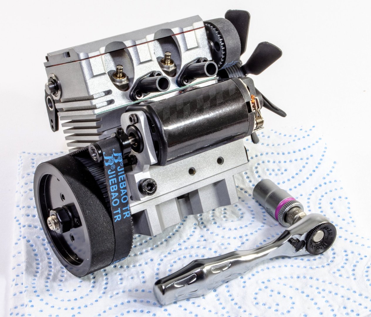
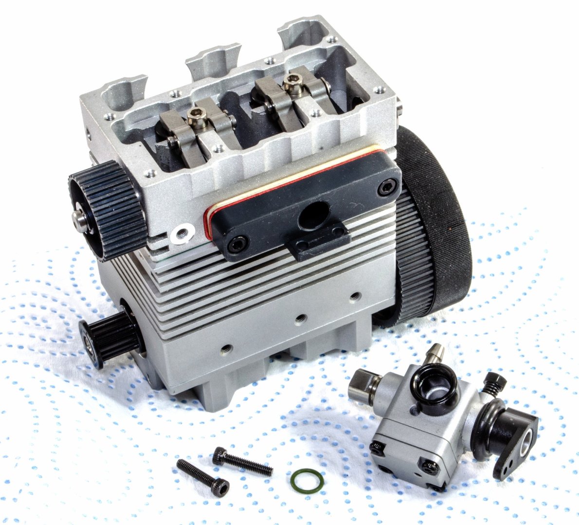
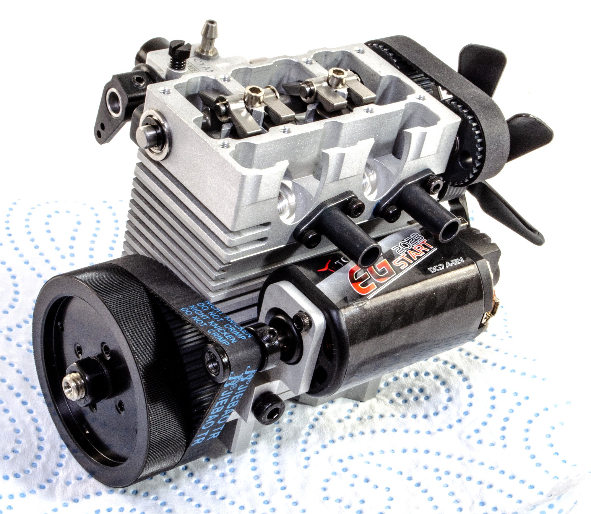
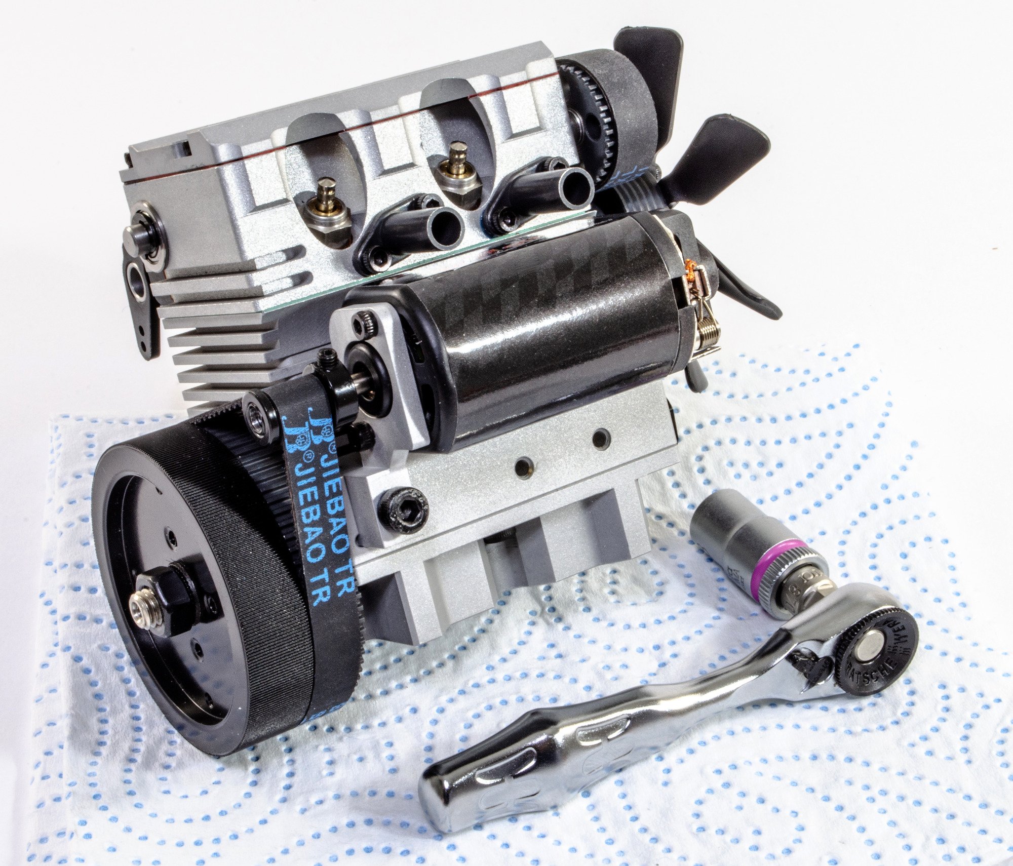
As you will have seen from the engine description, this engine is electrically started, and therefore needs a starter motor. This racy-looking unit is not assembled to the crankcase. The mounting for this is different from the one in the manual, but looks far easier to fit, and is very obvious. With the starter motor fitted, the second drive belt is slipped over the flywheel and onto a drive wheel on the starter motor. The latter is then tightened to it's shaft and the starter motor tightened to the mounting, ensuring the belt is tight.

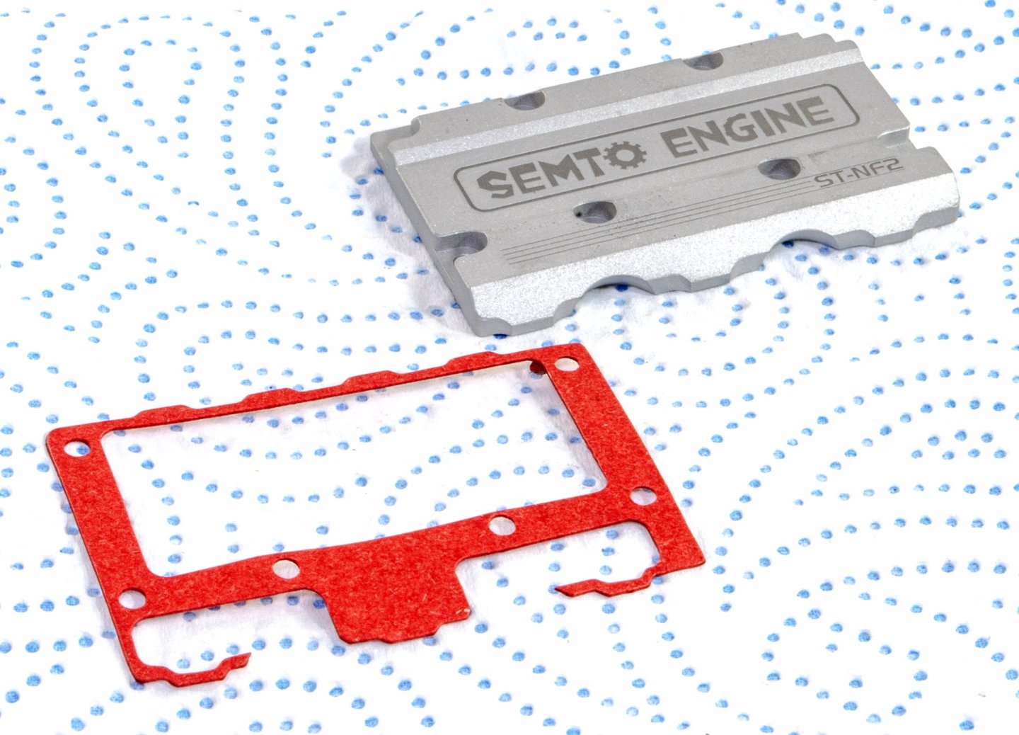
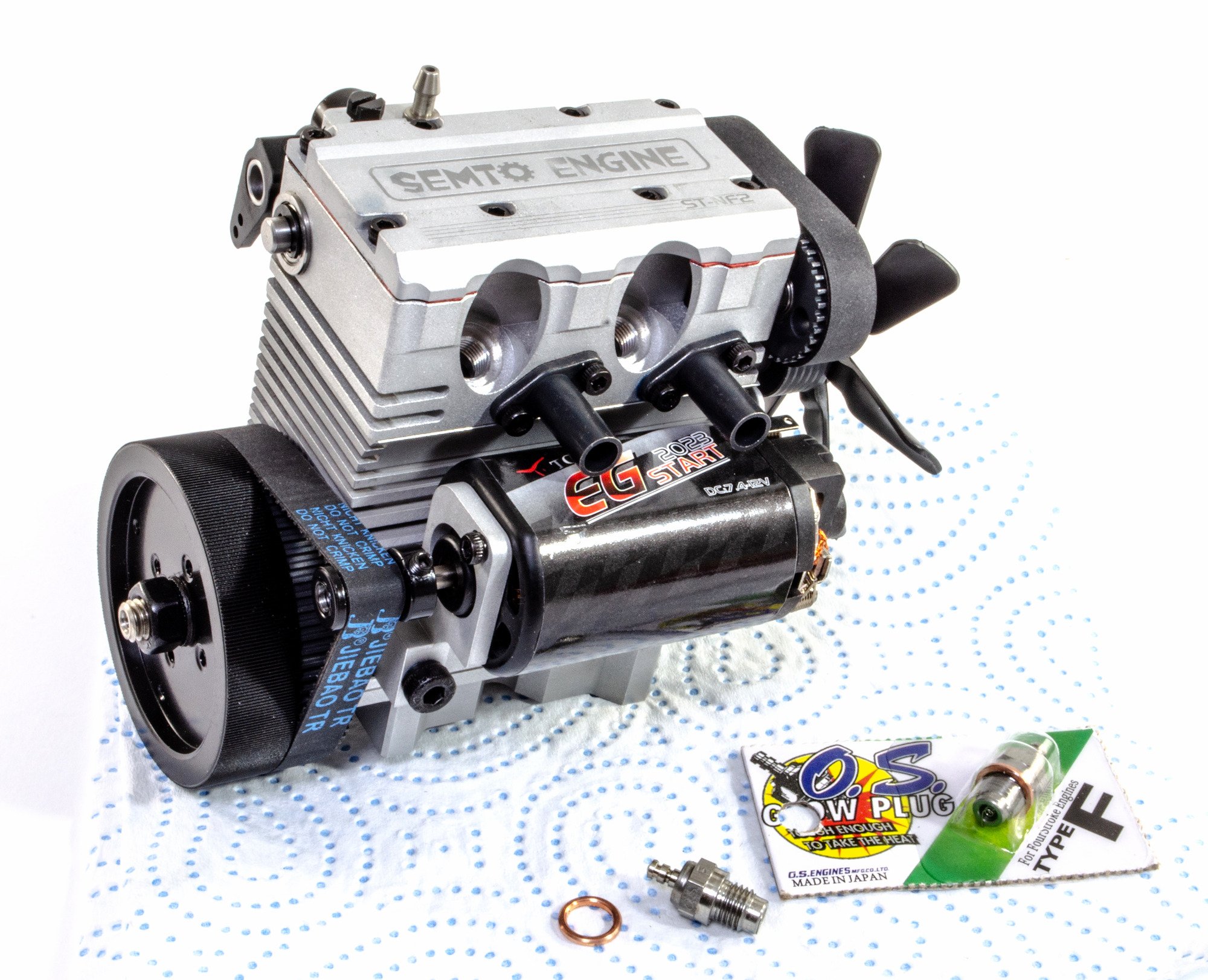
The last part of assembly is the cylinder head lid. Another gasket is used to seal this to the cylinder head.
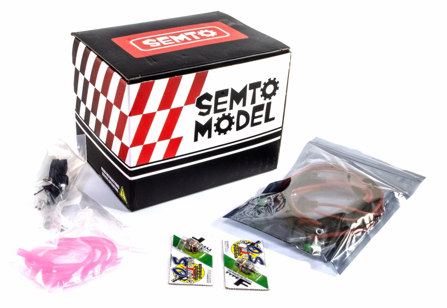
This engine needs to glow plugs which aren't supplied with the standalone engine. EngineDIY sent me the starter kit too, which supplies these plus, so these were now fitted to the engine. To secure these, you need a glow plug spanner, or a tool like I used here. The spanner in the base engine kit isn't suitable for this.

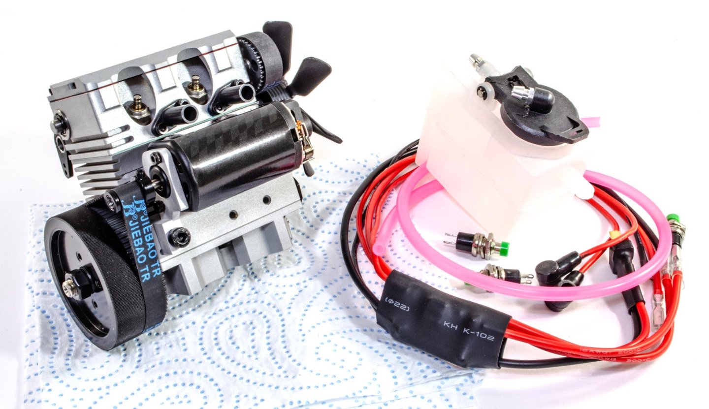
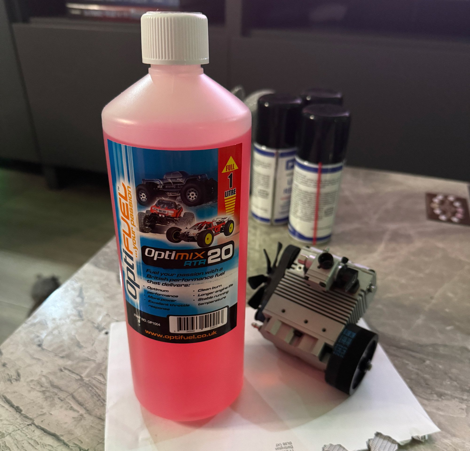
At this point, the engine is 'almost' ready to operate. What I need to do now is to find something that the engine can be securely fastened to whilst running. I am in the process of sorting this out. The sump does have threaded holes for the builder to utilise, so there's no problems there. In this photo, you can see the pink fuel tubing, the 100ml nitro fuel tank, and also the ignition set. You will of course need a battery to kickstart this too, and I need to source one of these. The engine also operates on 20 - 25% nitro fuel. I opted to buy the 20% fuel, simply for some engine longevity, plus I've not fired up a glow engine for almost 40yrs at this point!

As soon as I'm in a position to, I'll create a video to show my attempts at setting up this sweet little engine.
Conclusion
Pending running this engine, I have to say that the few hours I've spent in my workshop have been very enjoyable and this kit has fit together without any issue whatsoever. I would recommend using some thread-lock for the various bolts, making sure you don't get it anywhere you shouldn't. The instructions did pose a couple of questions for me, but those were resolved. In all, a wonderful little kit and for a working internal combustion engine, not too expensive either. the starter kit is most definitely recommended if you've never built an IC model kit before. In fact, this particular kit would be an ideal introduction into this genre.
My sincere thanks to EngineDIY for sending this kit out for review on Model Ship World. To buy this gorgeous little kit directly, click the link at the top of this article. For a discount, you can use the code JAMESHATCH.

- chris watton, GrandpaPhil, mtaylor and 3 others
-
 6
6
-
The sump is now securely fitted to the crankcase.

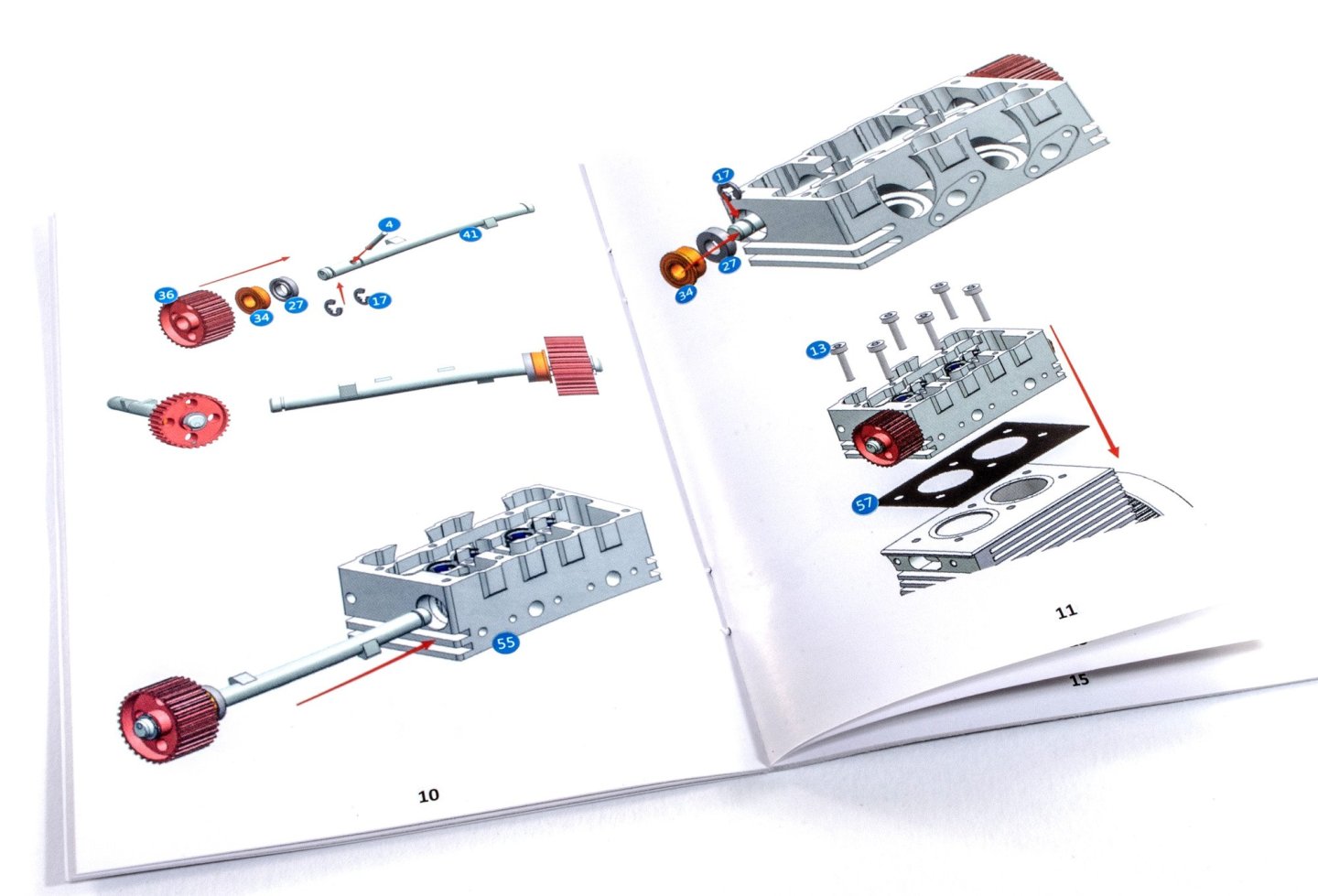
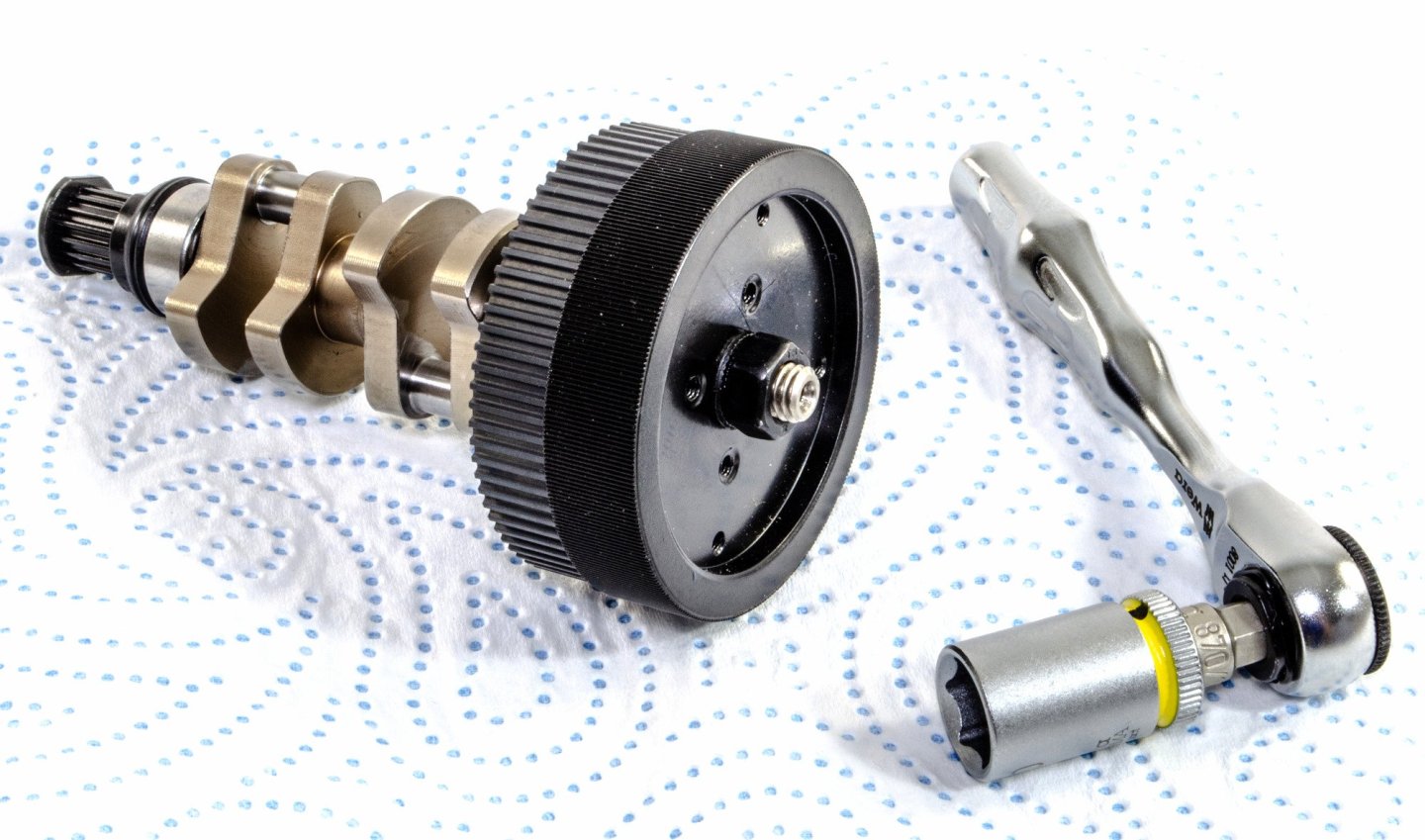
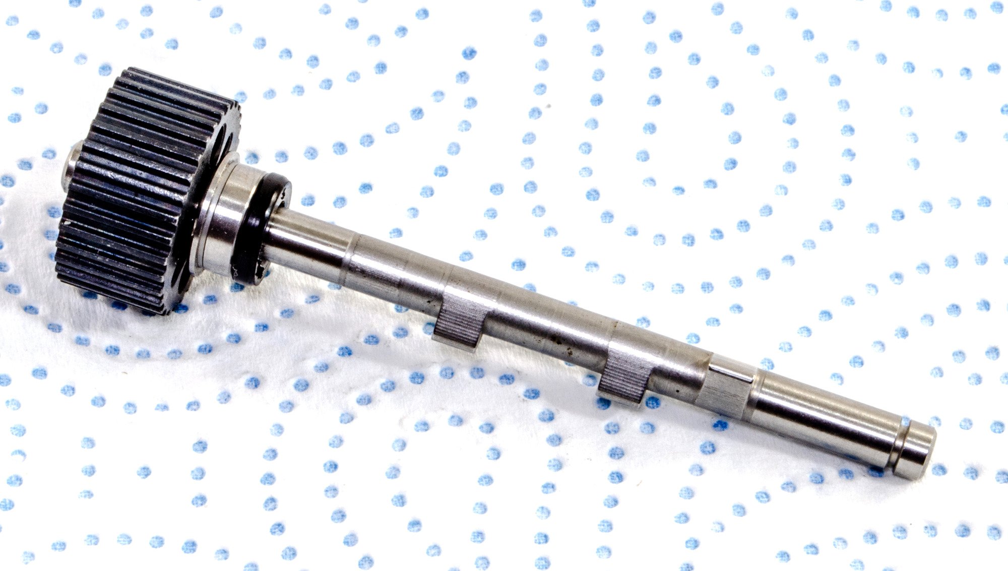
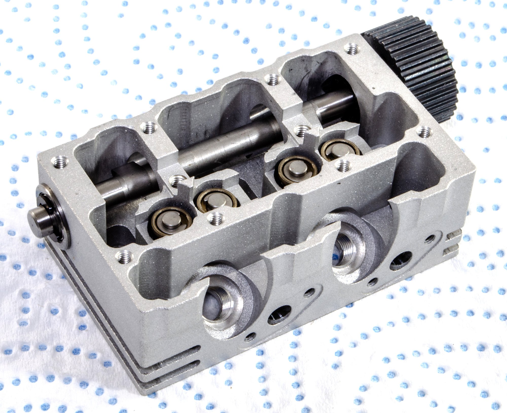
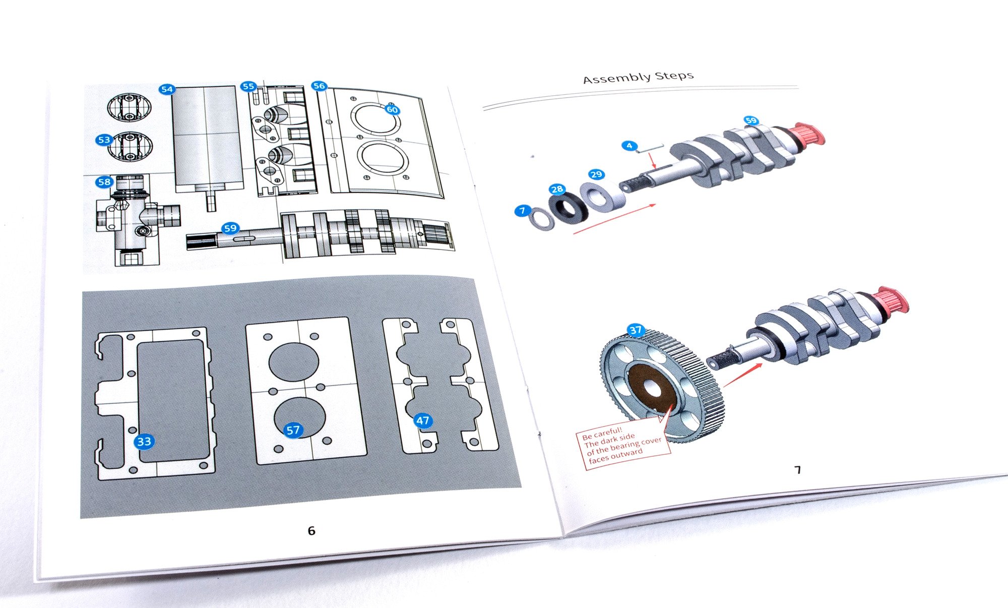
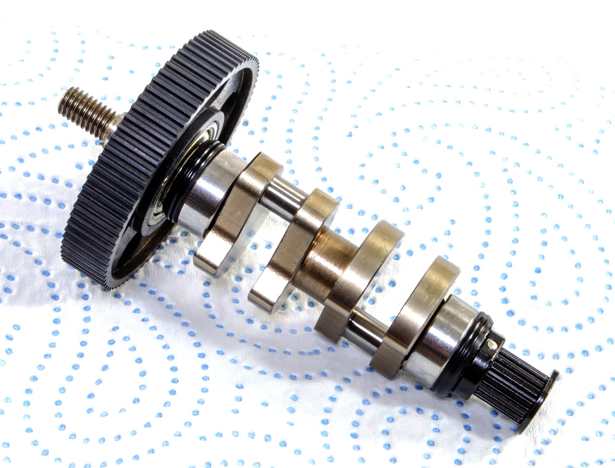
The next task is to assemble the camshaft. This model kit has a single unit. The assembly for this weren't too clear in the manual, so I resorted to watching the videos on the kit website, and it did appear to fit together the way I thought it should.
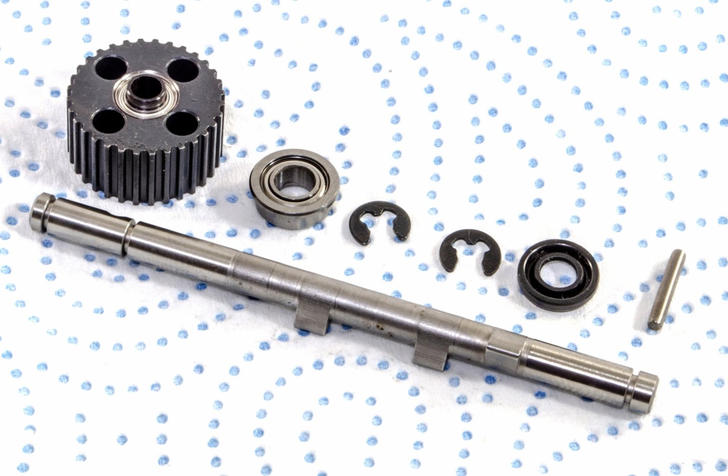

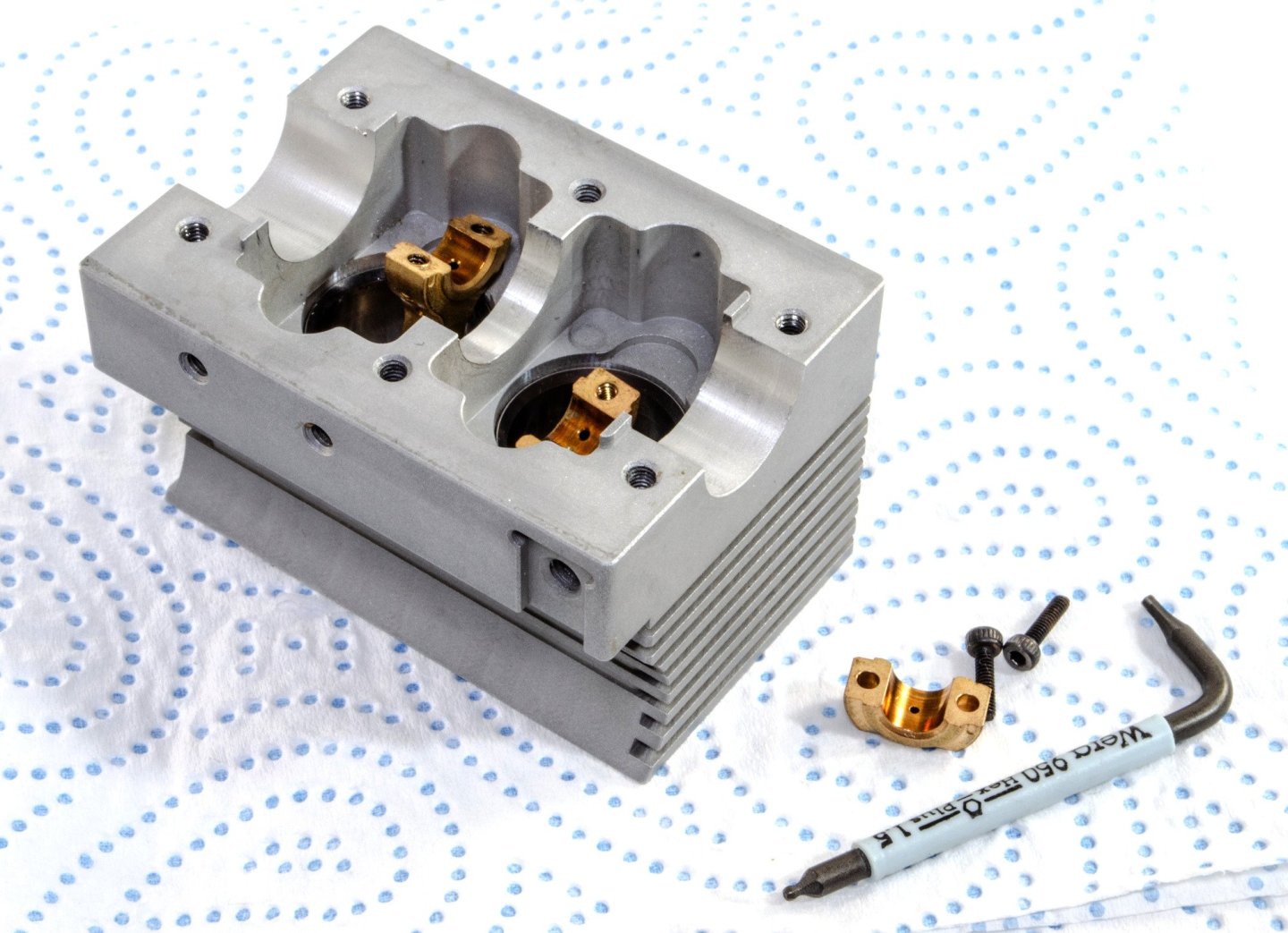
This is now inserted into the cylinder head block. Again, this is beautifully machined and comes with the four valves pre-installed. Some care was taken here to make sure the seals were properly seated at either side of the camshaft. A metal tube is supplied so you can tap the bearings fully home without damaging the bearings and camshaft.

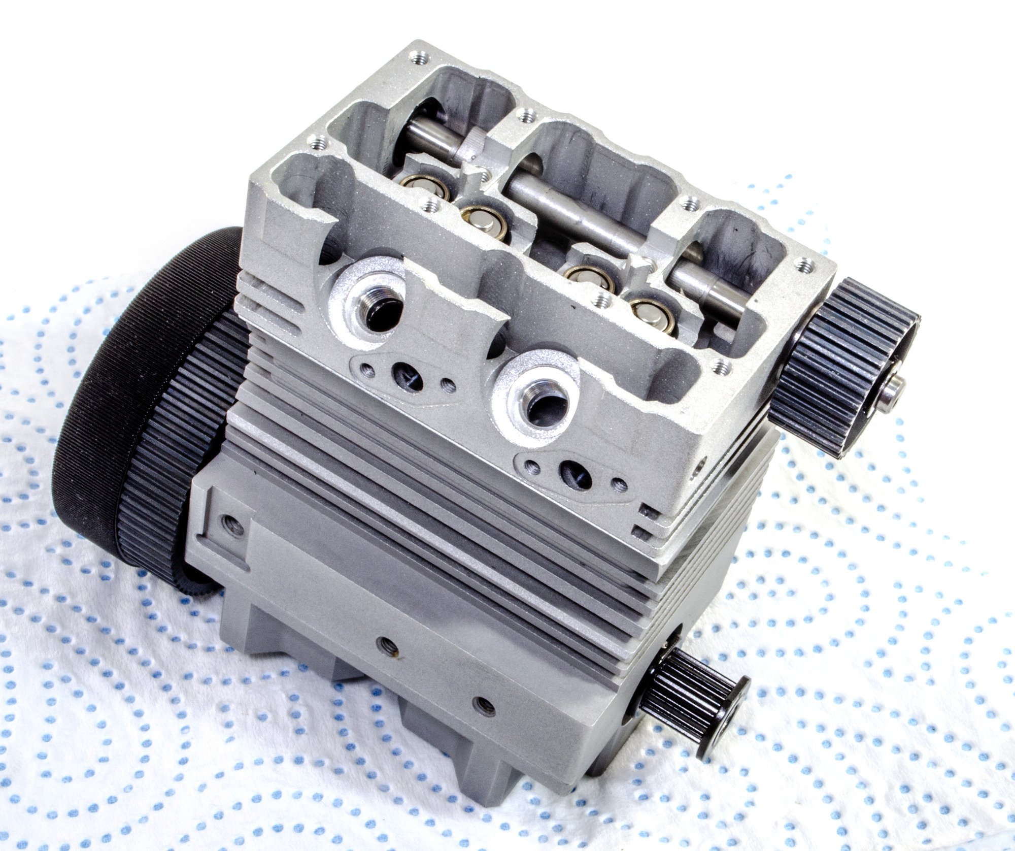
Using a gasket, the cylinder head block is attached to the crankcase.
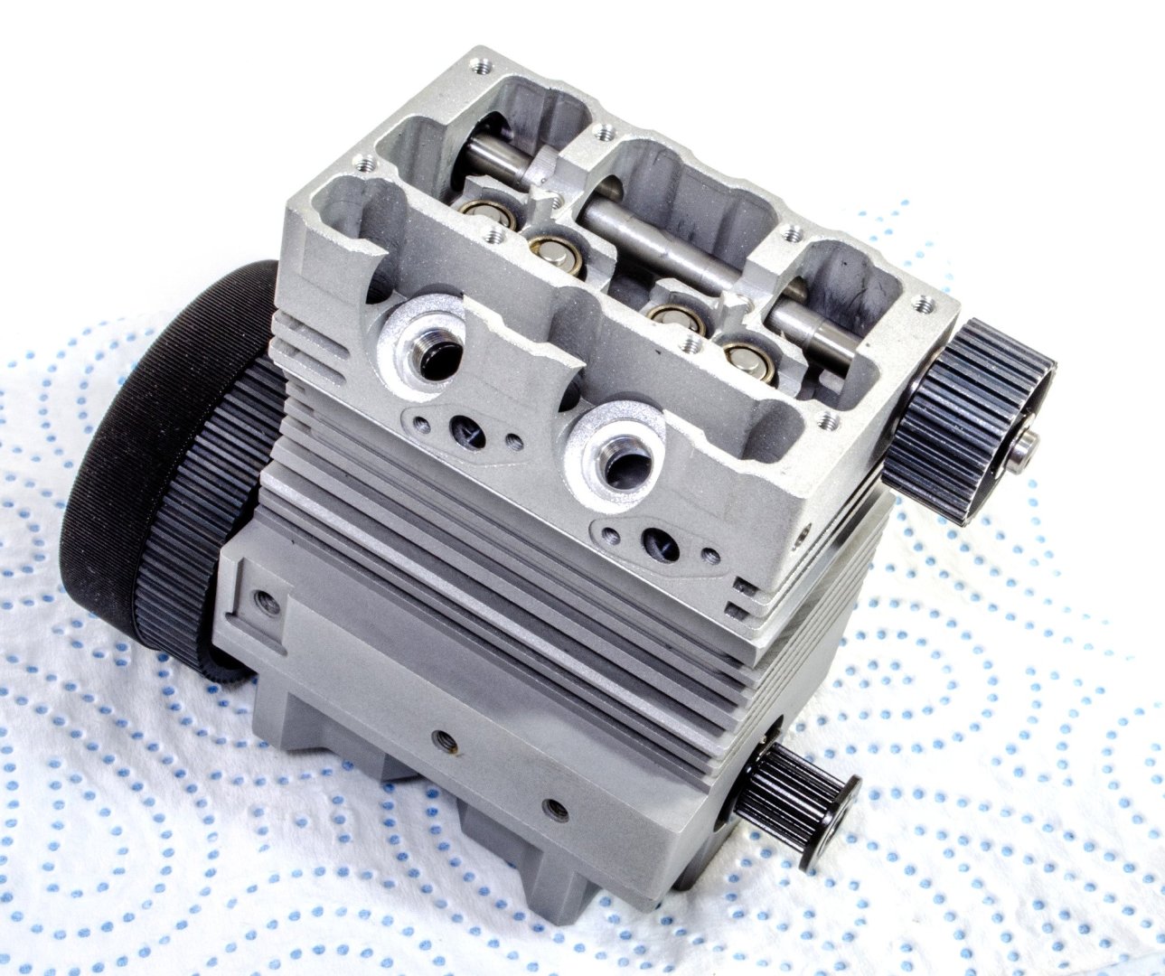
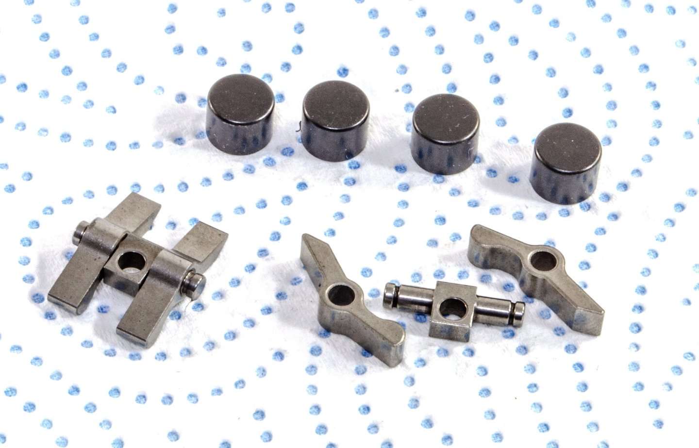
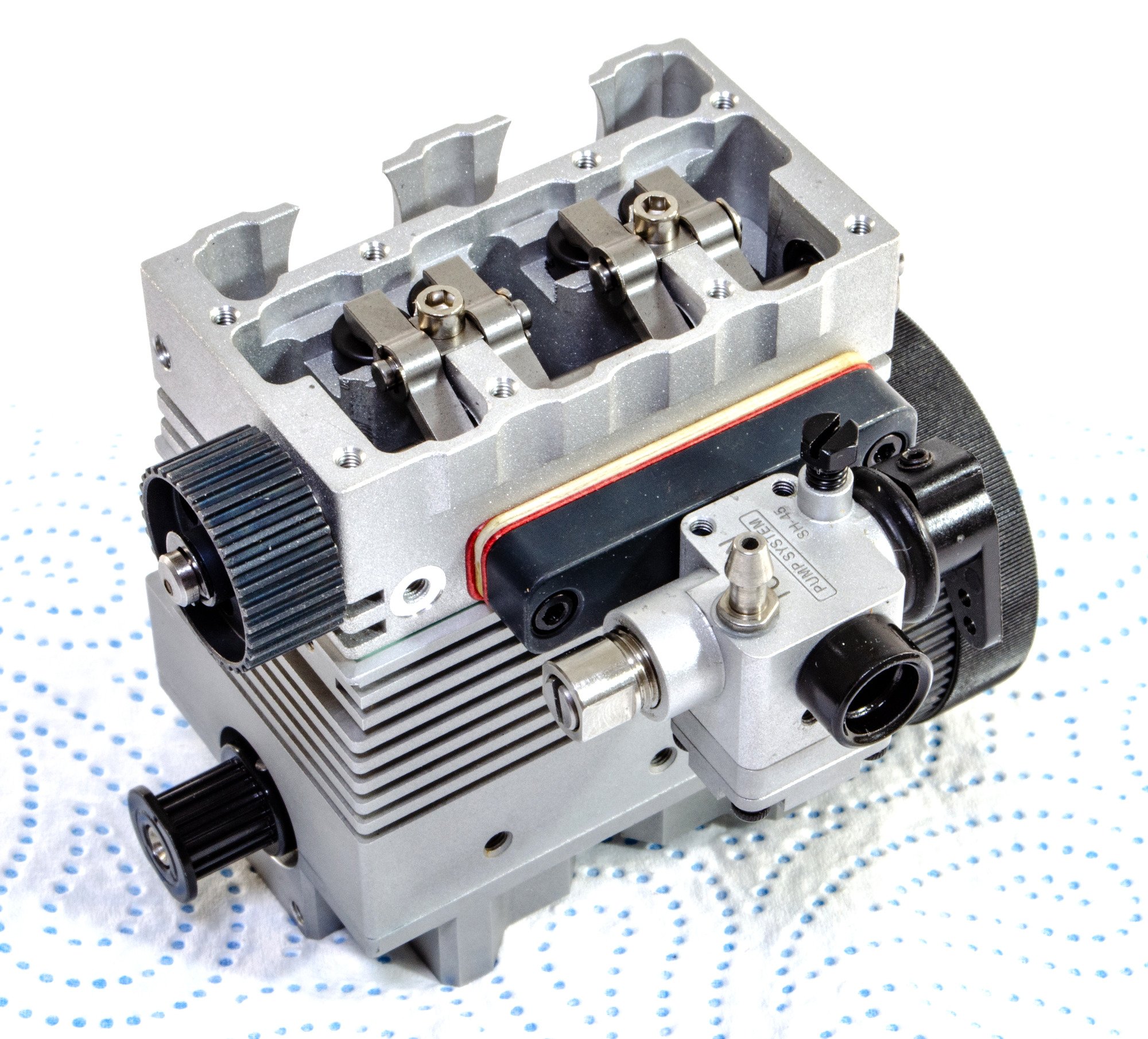
The rocker arms are now assembled, and along with the valve heads, fitted to the cylinder head.
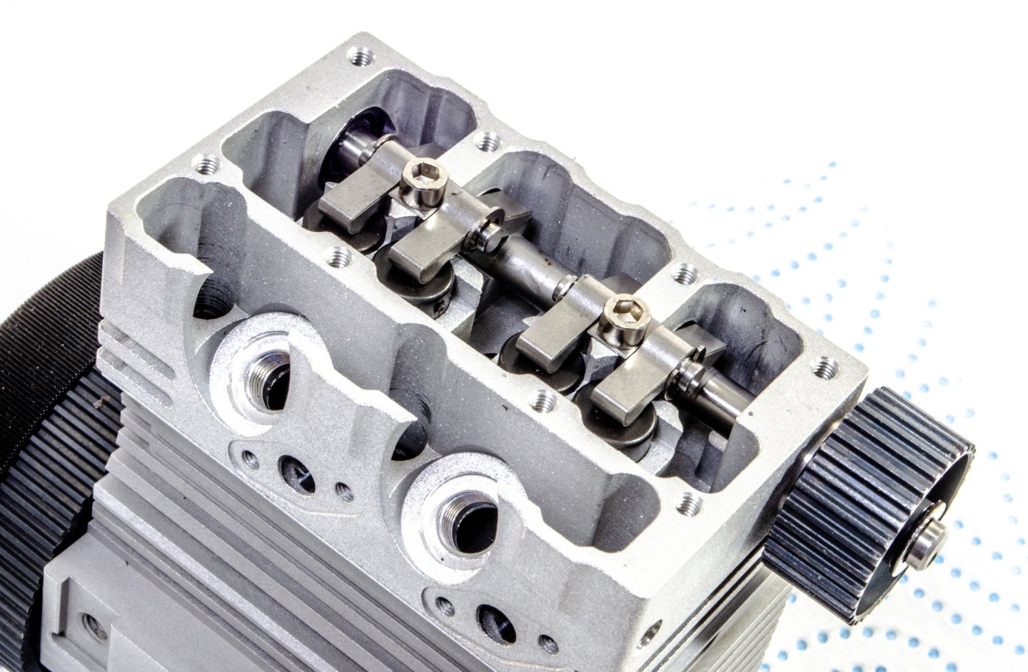
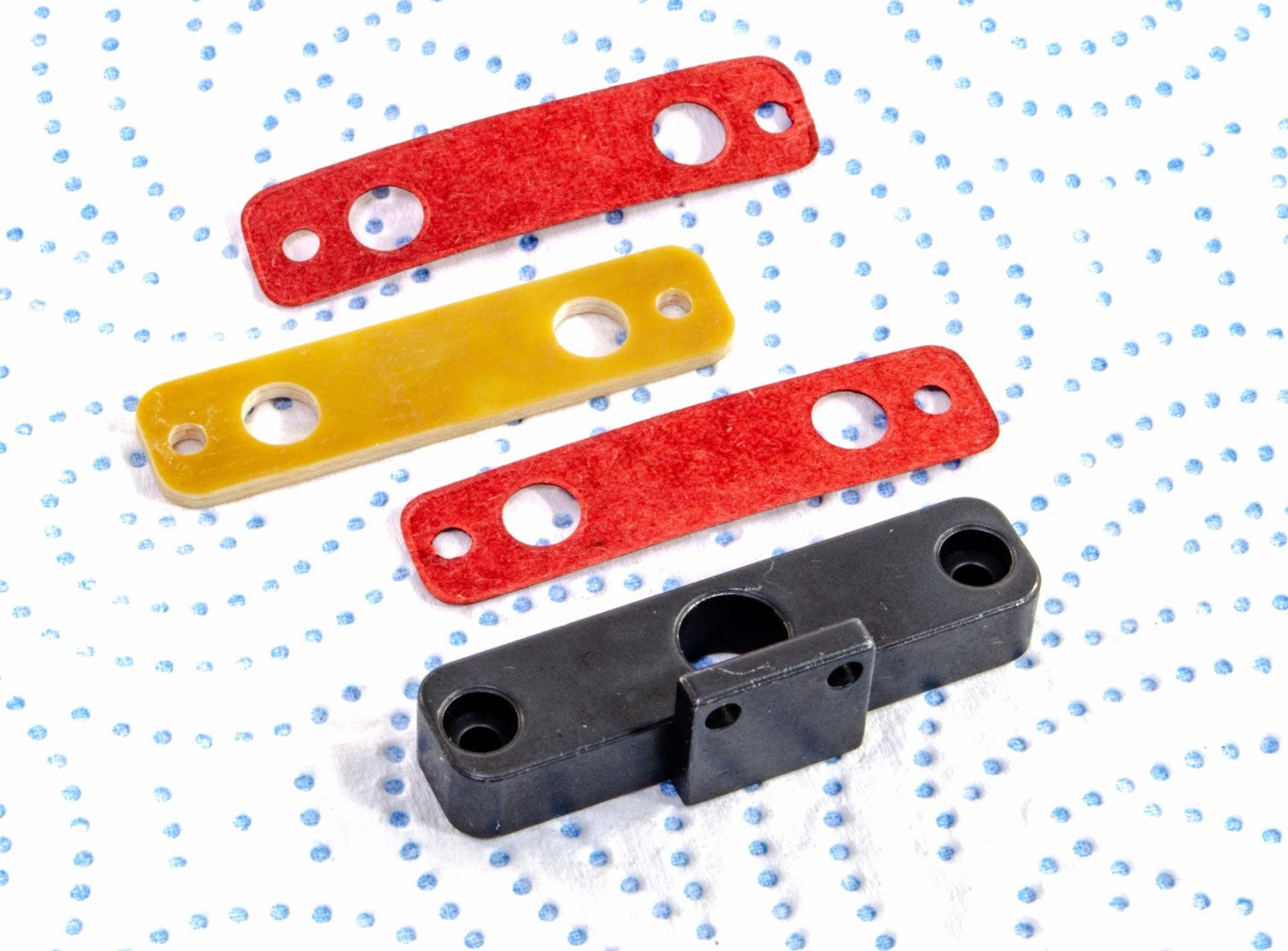
Before the carburettor can be fitted, this manifold and sealing gaskets are first installed. The manifold has been reworked from earlier versions and is different to the one shown in the manual. However, you can see it installed in its correct orientation.
The next parts to be installed are this sliding adjuster for the drive belt tensioning wheel, and another drive wheel. The adjuster is left slack for the time being as the drive belt will be quite tight when installed.

More to come....
- Ryland Craze, Kevin, Egilman and 4 others
-
7
-
7cc Double-cylinder 4-stroke Air-cooled Nitro Engine (and starter kit) by Semto
Available from EngineDIY for $298.98
A four-stroke (also four-cycle) engine is an internal combustion (IC) engine in which the piston completes four separate strokes while turning the crankshaft. A stroke refers to the full travel of the piston along the cylinder, in either direction. The four separate strokes are termed:
Intake: Also known as induction or suction. This stroke of the piston begins at top dead center (T.D.C.) and ends at bottom dead center (B.D.C.). In this stroke the intake valve must be in the open position while the piston pulls an air-fuel mixture into the cylinder by producing a partial vacuum (negative pressure) in the cylinder through its downward motion.
Compression: This stroke begins at B.D.C, or just at the end of the suction stroke, and ends at T.D.C. In this stroke the piston compresses the air-fuel mixture in preparation for ignition during the power stroke (below). Both the intake and exhaust valves are closed during this stage.
Combustion: Also known as power or ignition. This is the start of the second revolution of the four stroke cycle. At this point the crankshaft has completed a full 360 degree revolution. While the piston is at T.D.C. (the end of the compression stroke) the compressed air-fuel mixture is ignited by a spark plug (in a gasoline engine) or by heat generated by high compression (diesel engines), forcefully returning the piston to B.D.C. This stroke produces mechanical work from the engine to turn the crankshaft.
Exhaust: Also known as outlet. During the exhaust stroke, the piston, once again, returns from B.D.C. to T.D.C. while the exhaust valve is open. This action expels the spent air-fuel mixture through the exhaust port.
Four-stroke engines are the most common internal combustion engine design for motorised land transport, being used in automobiles, trucks, diesel trains, light aircraft and motorcycles. The major alternative design is the two-stroke cycle.
From Wikipedia
The kit
First, some real important information about the engine.
- Engine Type: Nitro Internal Combustion Engine Model
- Displacement: 7 (3.5*2)cc
- Cylinder: Inline Double-cylinder
- Stroke: Four Stroke
- Cyilinder Diameter: 16.6mm
- Stroke: 17.00mm
- Speed: 4000-16000rpm
- Power: 0.6ps (0.59 horsepower)
- Cooling Mode: Air Cooling
- Lubrication Mode: Mixed Oil Lubrication
- Starting Mode: Electric
- Ignition Mode: Ignition Modules (Not Included)
- Type of Electric Plug: F-type Four-stroke Electric Plug (Not Included)
- Starting Voltage: 7.4V 2S Li battery (Not Included)
- Fuel Type: 20-25% Nitro Fuel
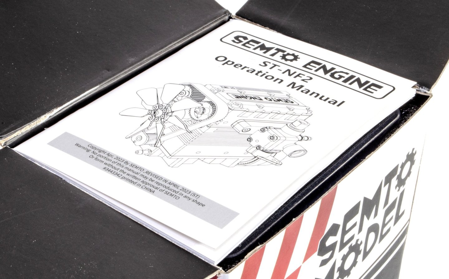
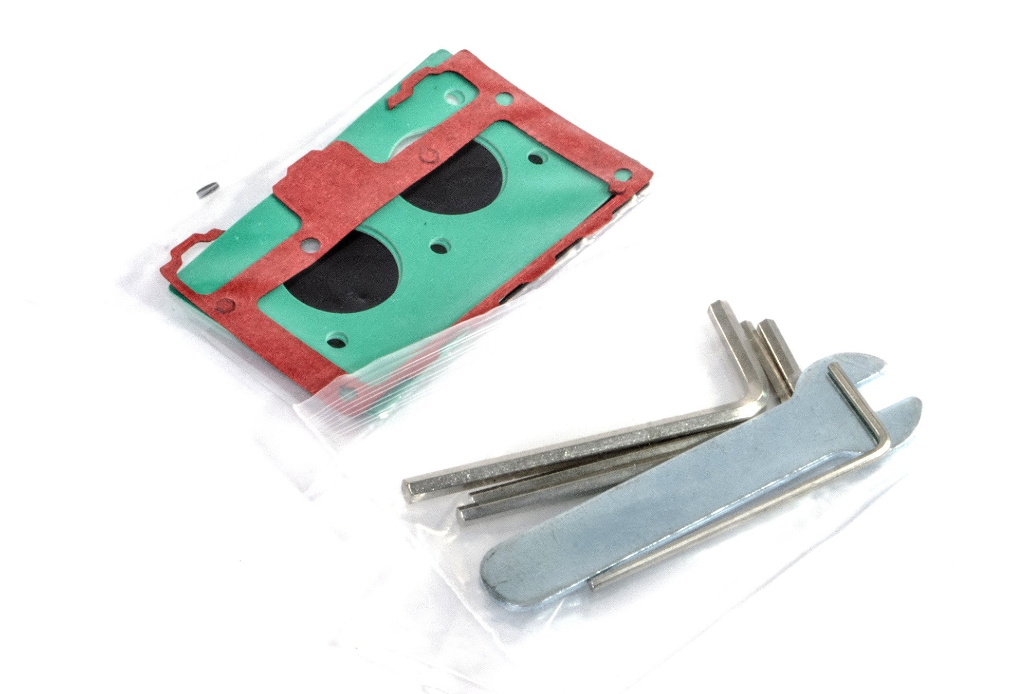
For what is essentially a real engine, in terms of this being one that requires fuel for internal combustion, the box is quite diminutive but weighs almost a kilo. Inside the box, the first thing you'll see is the instruction manual. This is a nice little booklet that is mostly quite easy to follow, with a few caveats that can easily be cleared up with a few views of the videos on the EngineDIY website. The illustrations are in colour, clearly drawn and also illustrate where lubricant is needed. What perhaps isn't as clear are the use of the very useful extra 'tools' included in the kit, that aid the insertion of the pistons and to seat bearings. I'll explain that soon. The instructions also include a map of each of the FOUR parts trays and where to find the specific parts for each assembly, both in the trays and in the compartmental box of screws, circlips, etc.

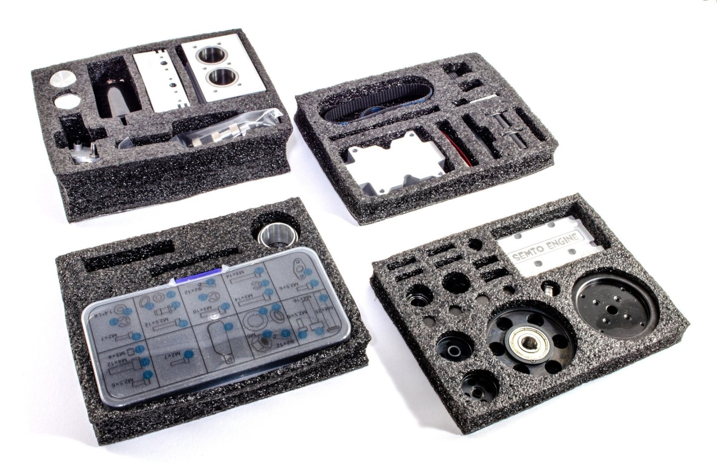

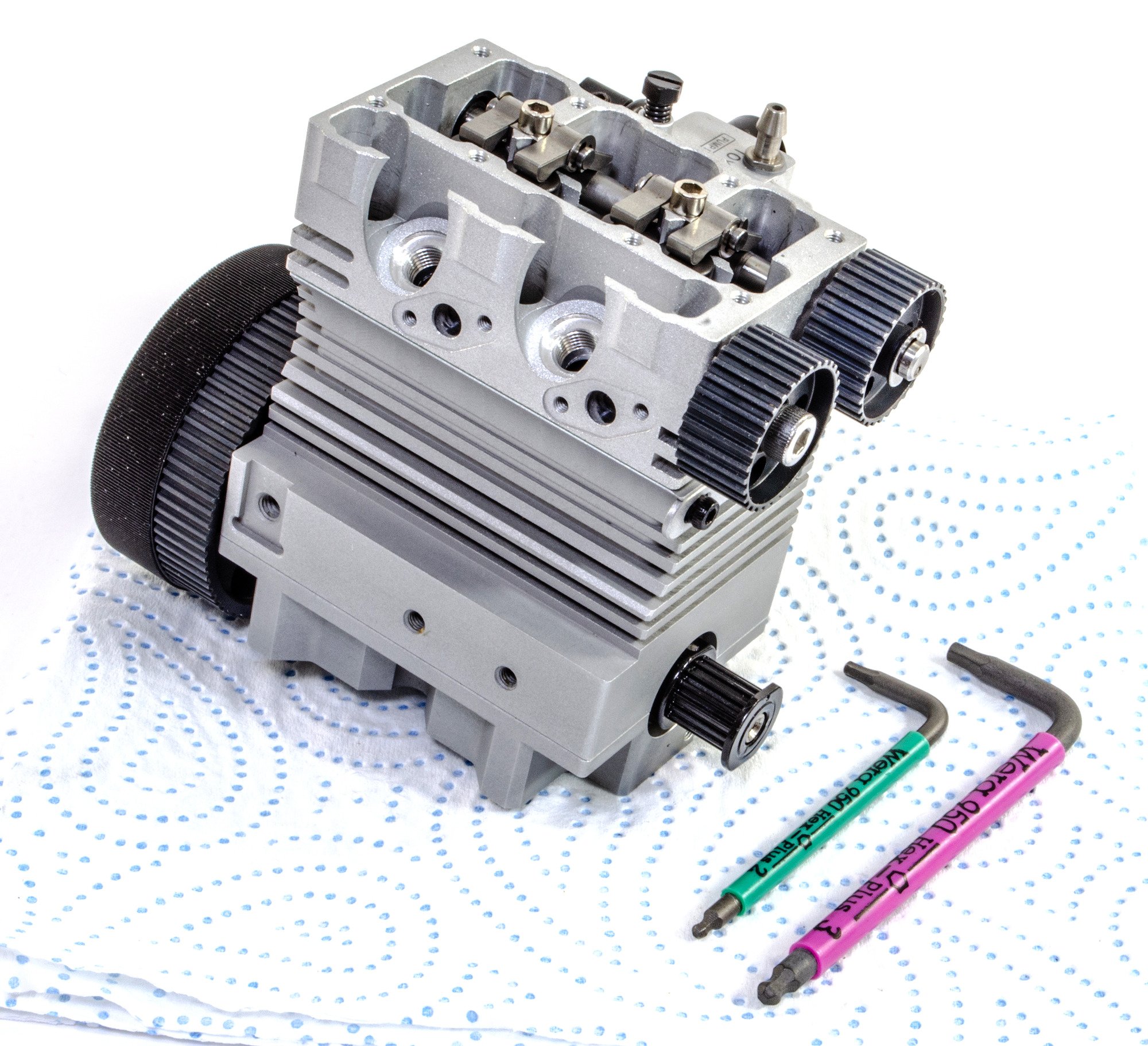
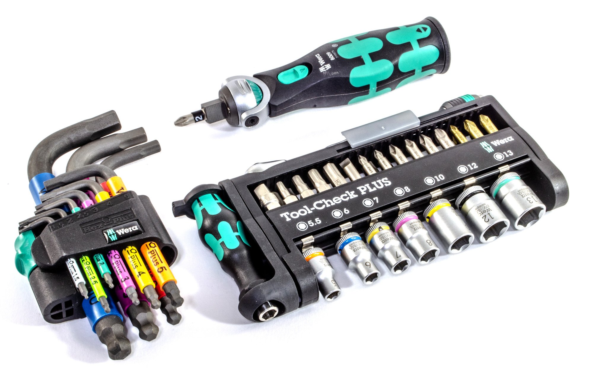
As you can see, the kit does supply hex keys and also a spanner. However, I took the opportunity to use my new Wera tool sets that I'd seen in other excellent videos of some of the EngineDIY builds.

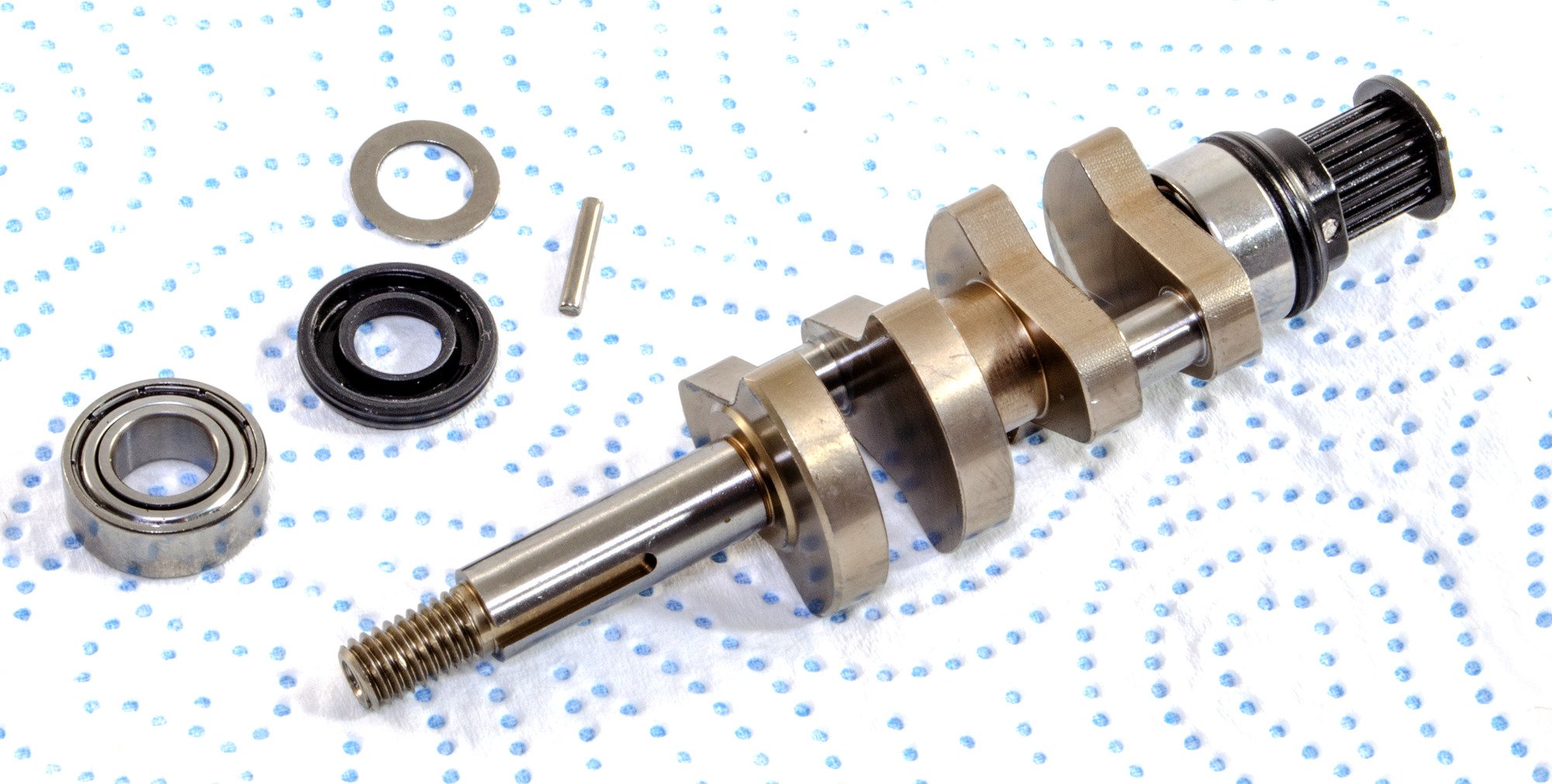
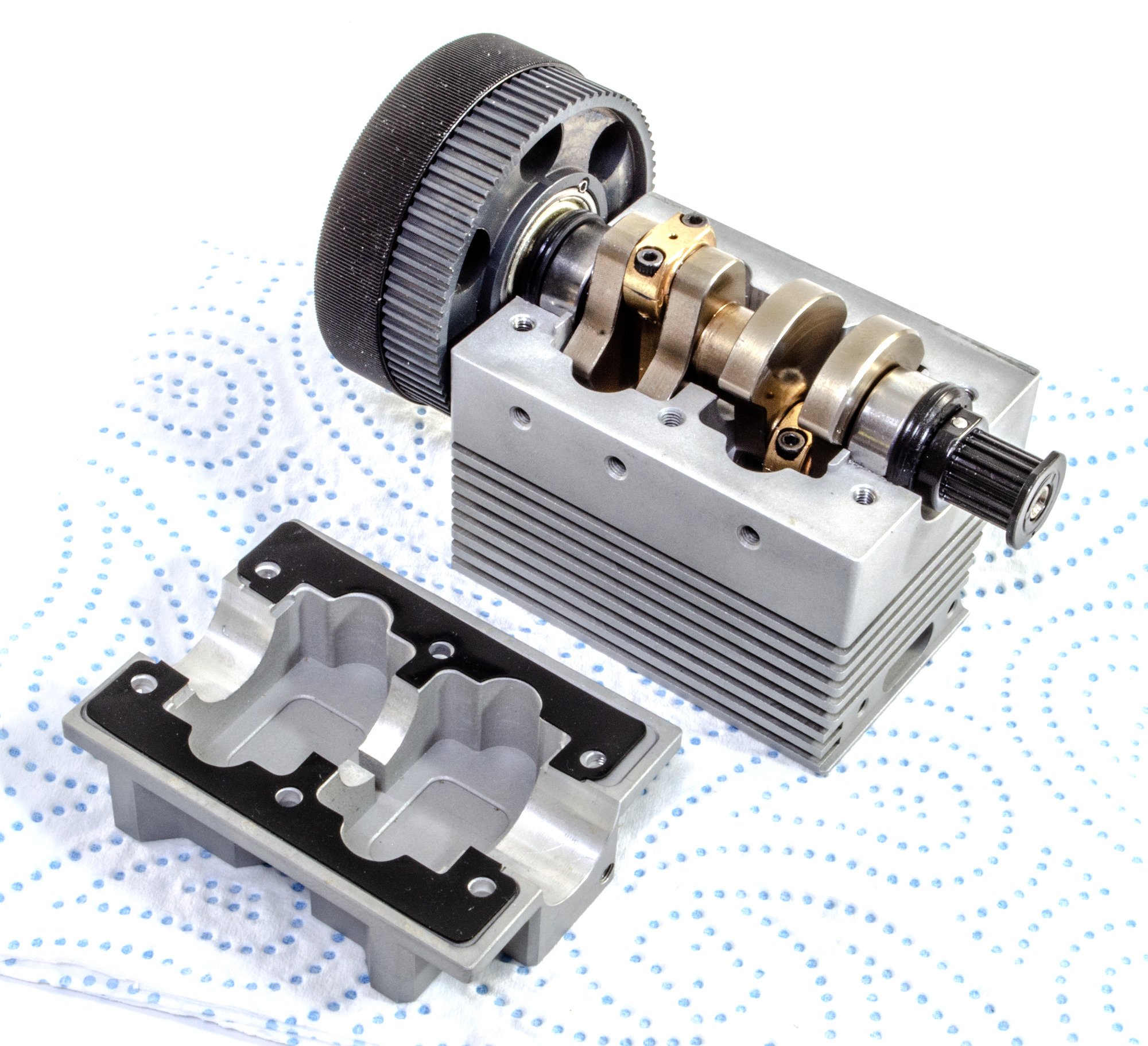
The first point of assembly is the crankshaft. This part is supplied in a plastic sleeve which protected crankshaft's mineral oil film. The part is also beautifully machined, as you can see, and comes with a few parts pre-attached to one end. The additional parts shown have to be attached in a very specific way, as does everything else in a kit which you will run with nitro fuel.


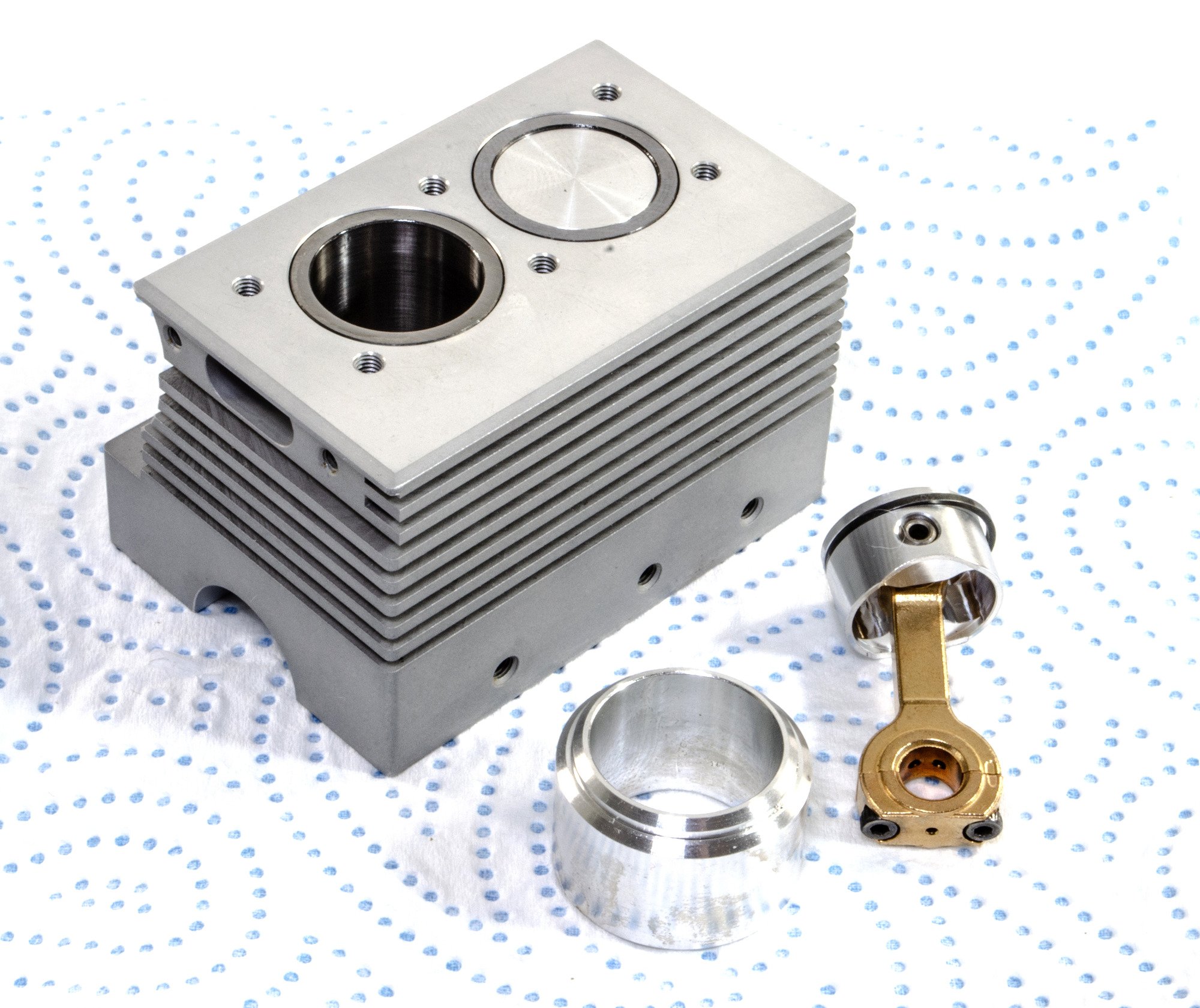
The next task is to insert the pistons into the crankcase. The piston rings are supplied in the piston sleeves and you need to very carefully remove these from there. The rings are then slipped onto the pistons and the inside of the sleeve lubricated with a little grease. The rings are metal and need to be compressed against the pistons before insertion to the sleeve. For this, a metal ring is supplied which has a slightly conical internal profile. You pop the piston into the top of this part, sat atop the crankcase, and then gently push the piston downwards through the ring until it's fully inserted within the piston sleeve. The ring forces the piston ring to close up enough for the piston to be inserted. It's simple and it works exceptionally well. Note that the pistons have a brass saddle that needs to be removed before you add the pistons. It also has an elongated indent which you can clearly see on the right hand side of the brass area. It's important that those are matched back up later.

The assembled crankshaft is now fitted to the crankcase, and the crankshaft connected to pistons. The sump is also now fitted, and a gasket used to seal the sump to the crankcase.

More to come....
- GrandpaPhil, mtaylor, AJohnson and 5 others
-
8
-
-
AND lastly.
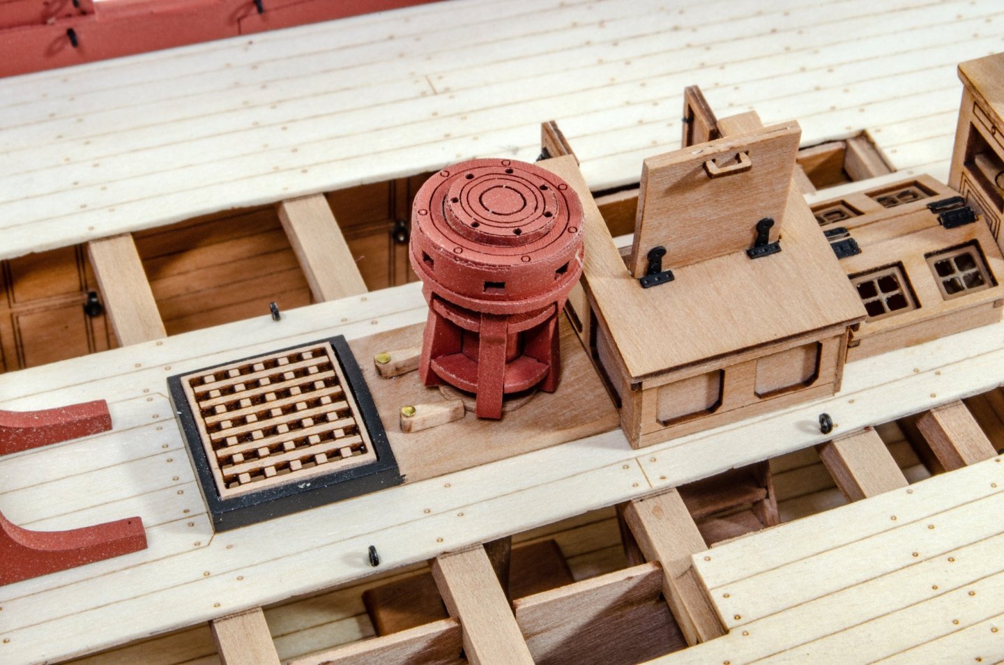
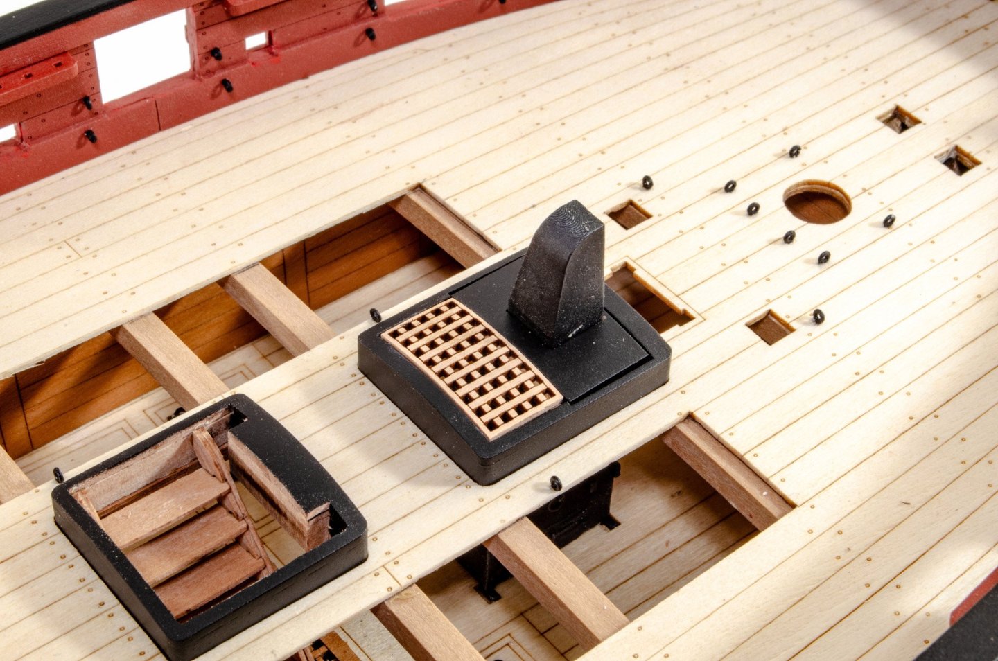
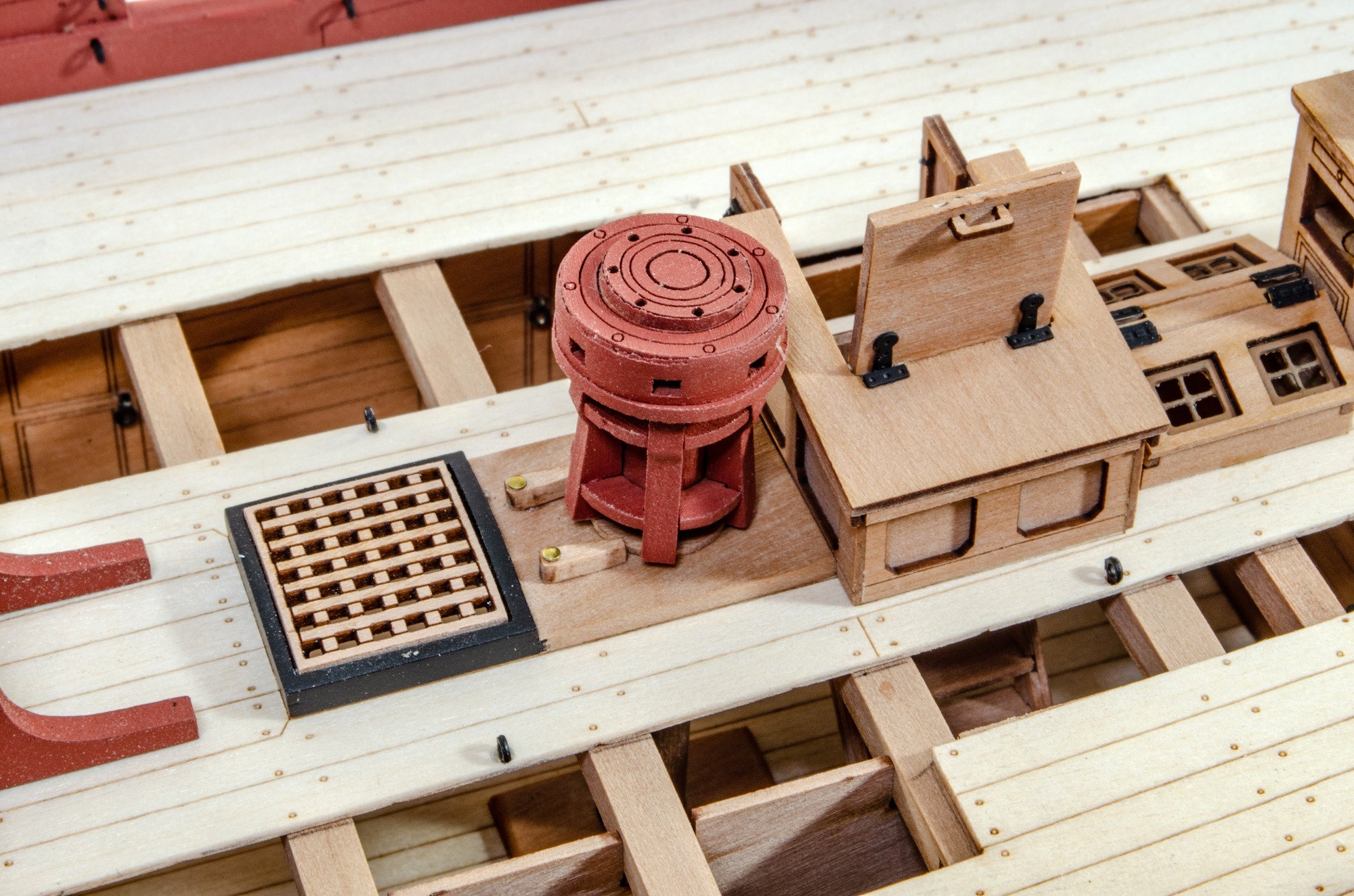
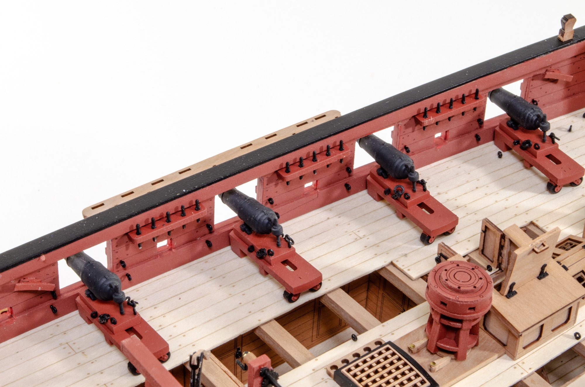
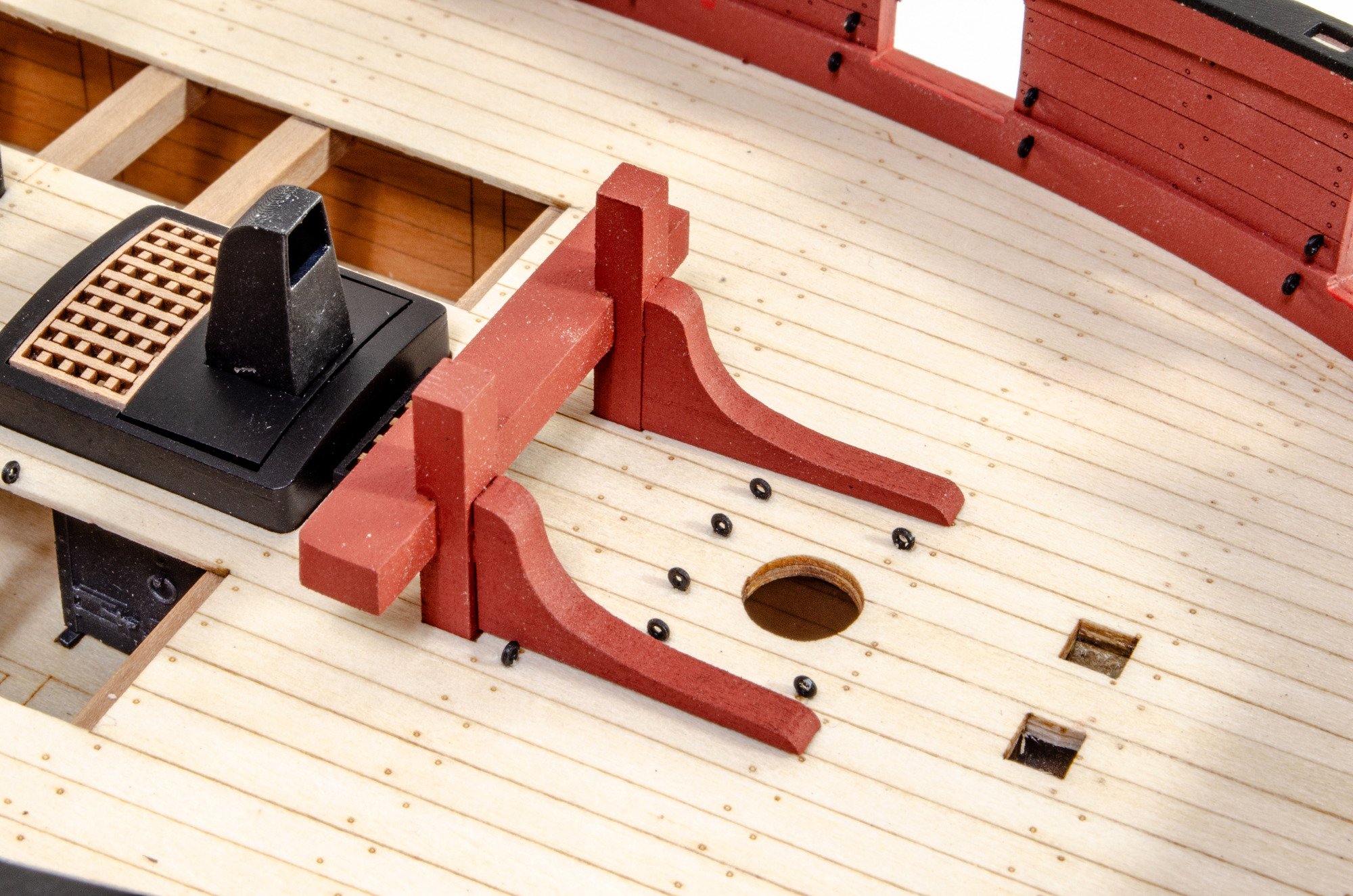
3D printed chimney is glued in, as is the capstan and pawls.

Might as well add all those guns too!

The channels are now fitted, and the belaying pins added.


Pumps etc. fitted.

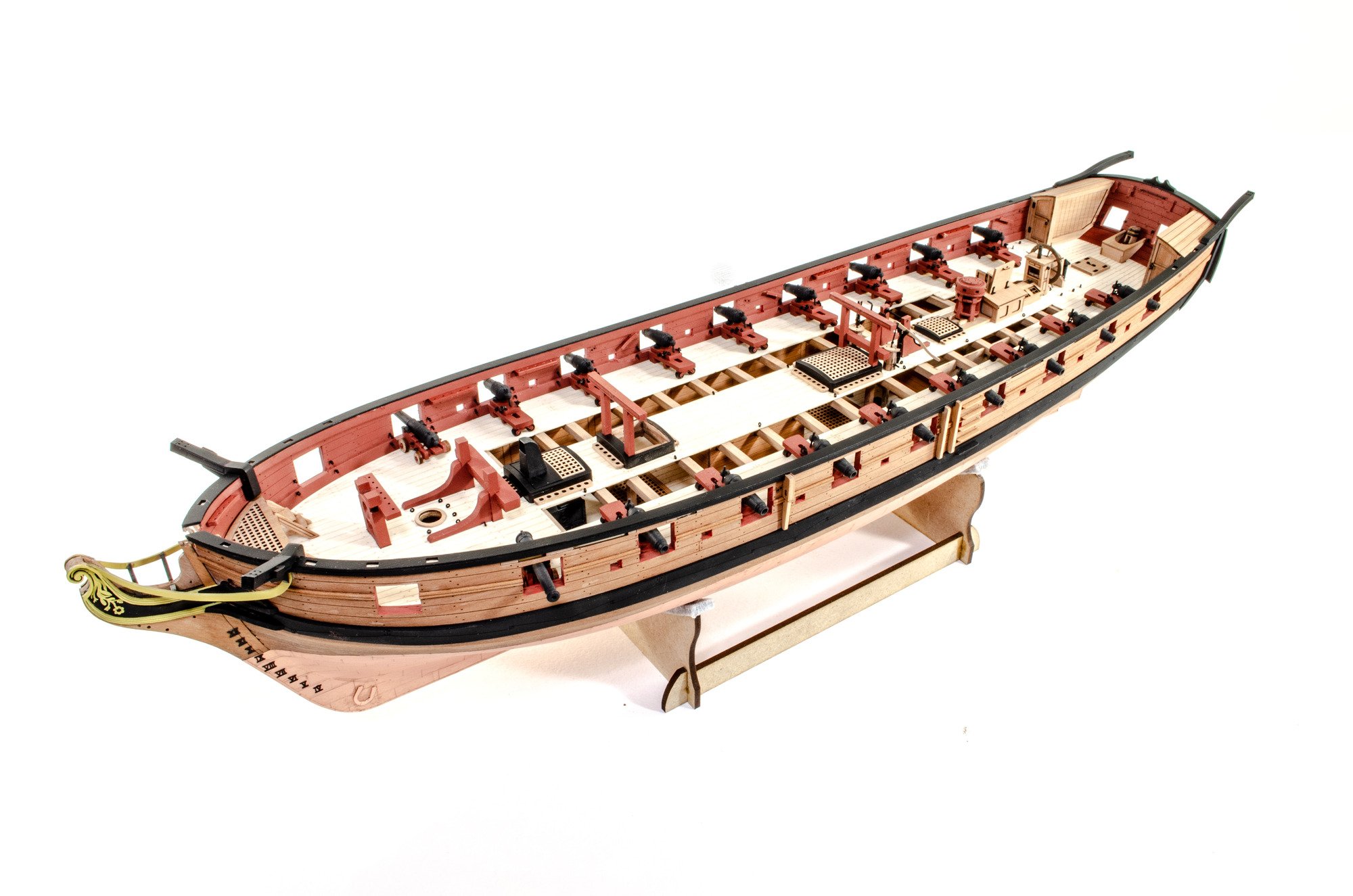
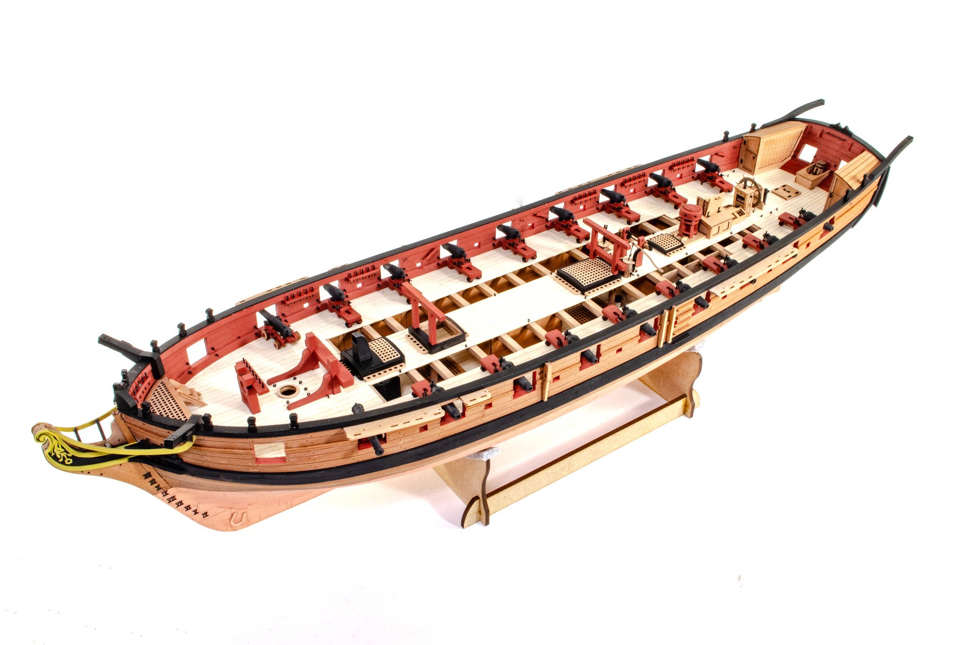
And Harpy now looks like this...

Now I need to add the finishing touches and move onto the masts.
-
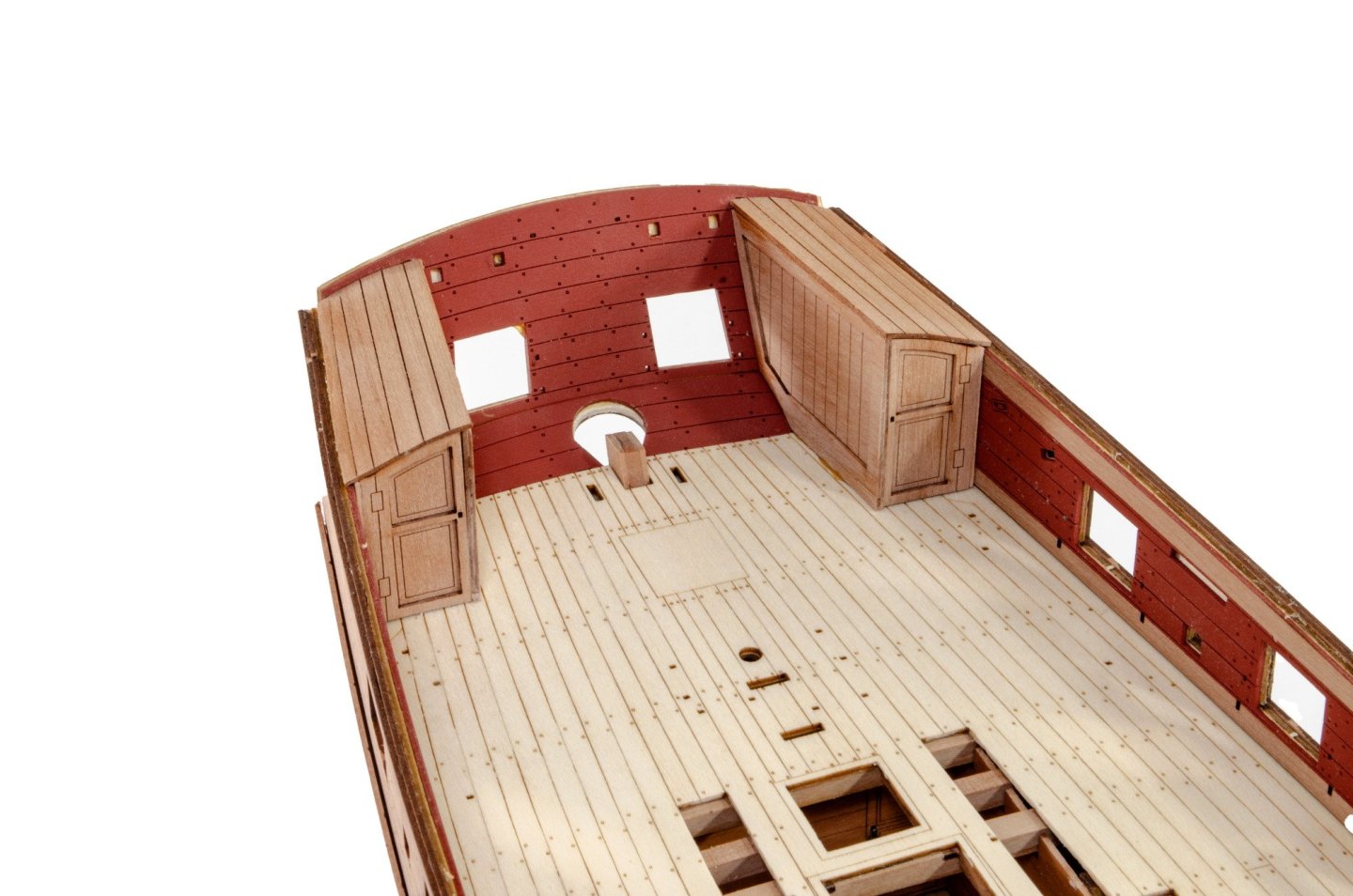
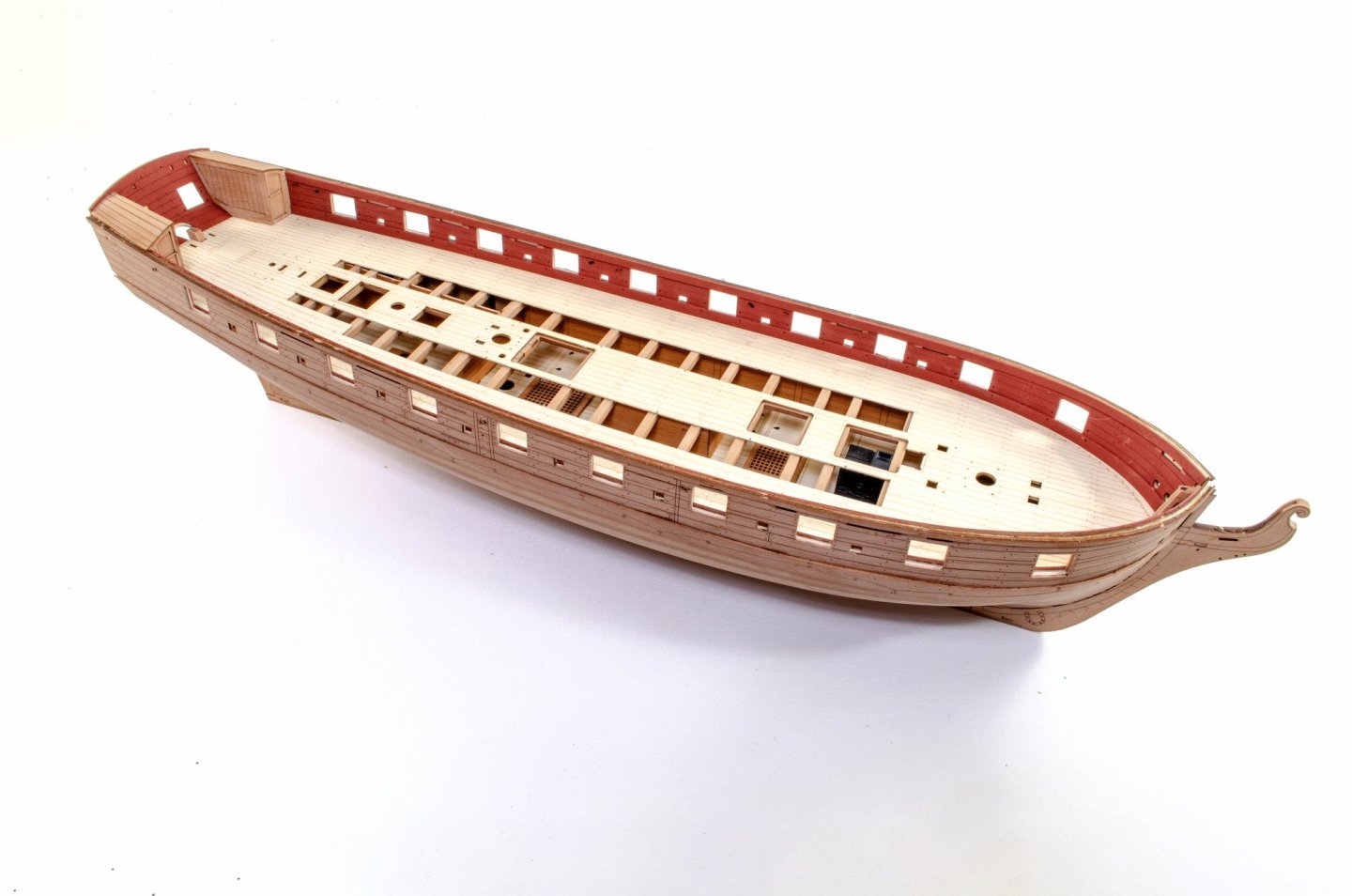
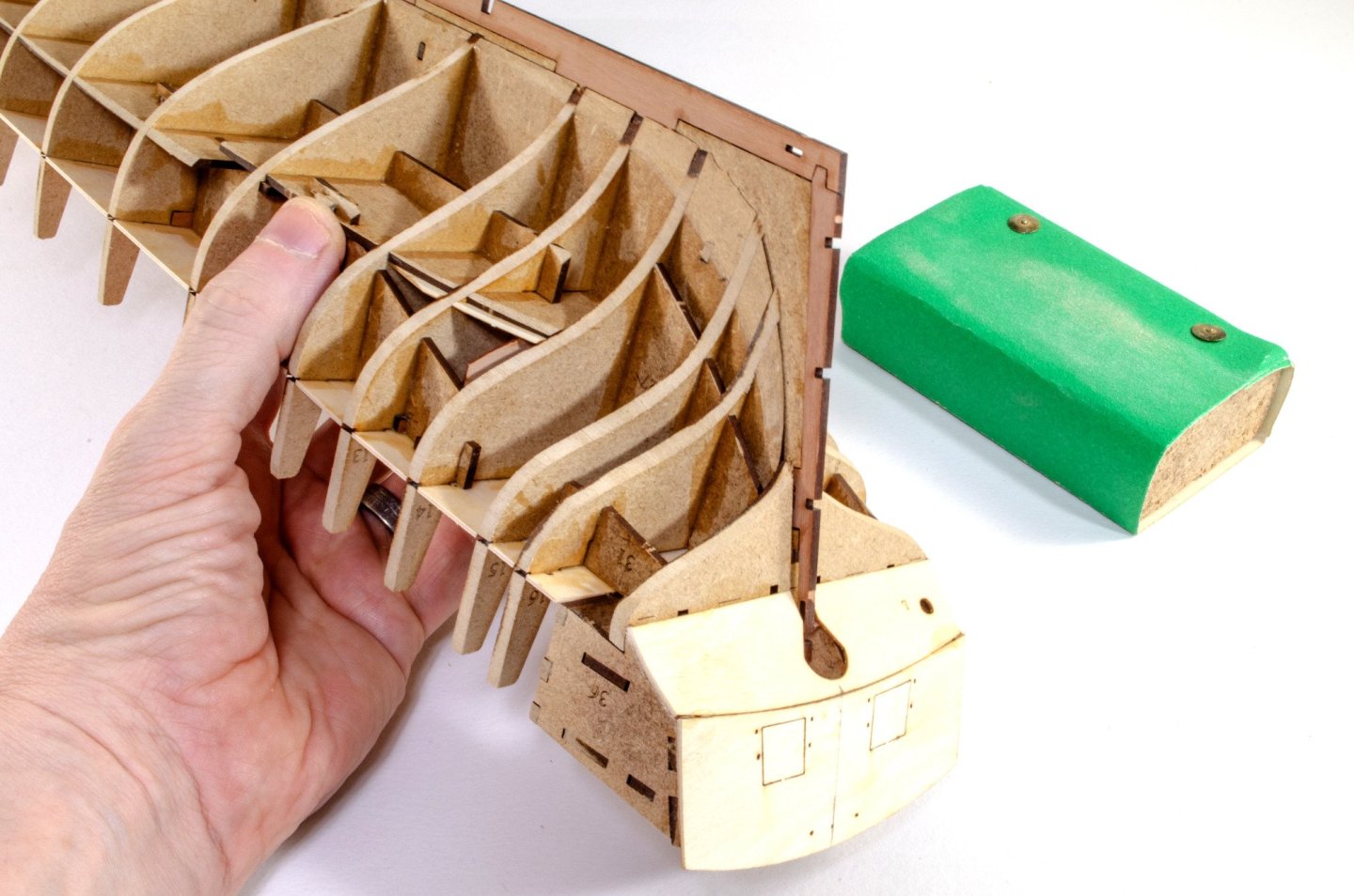
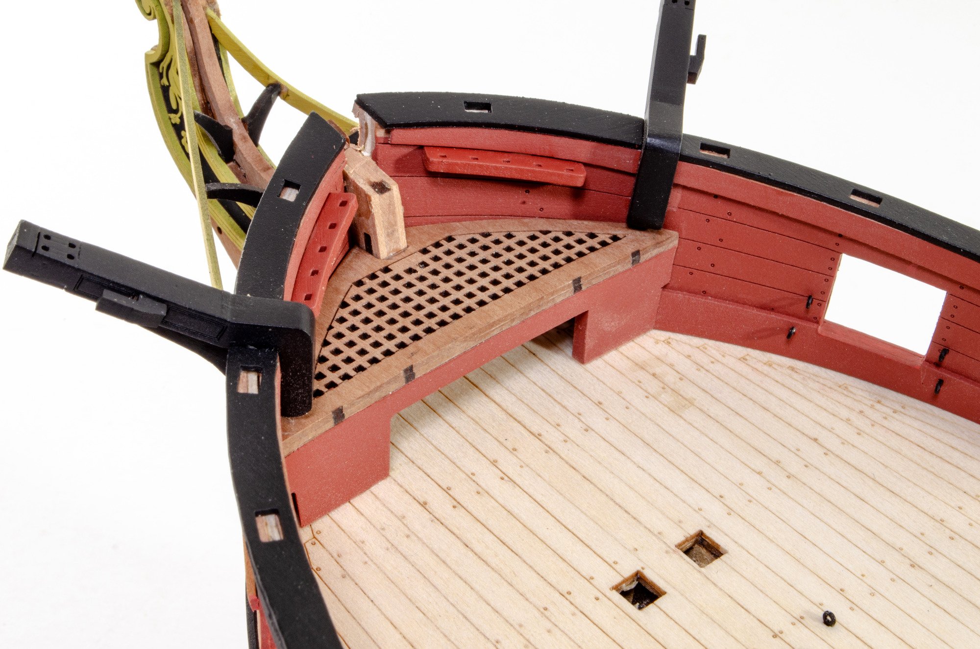
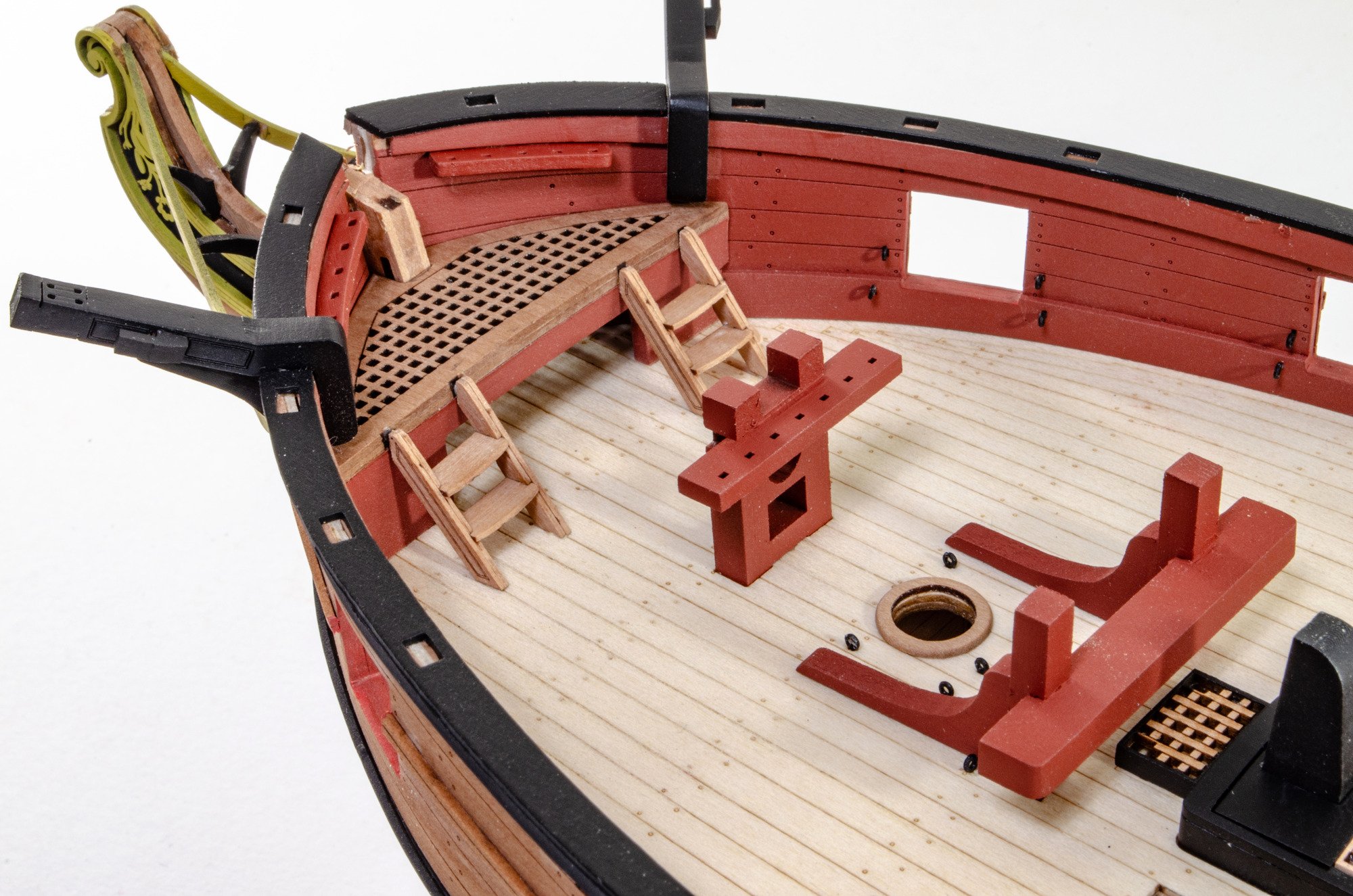
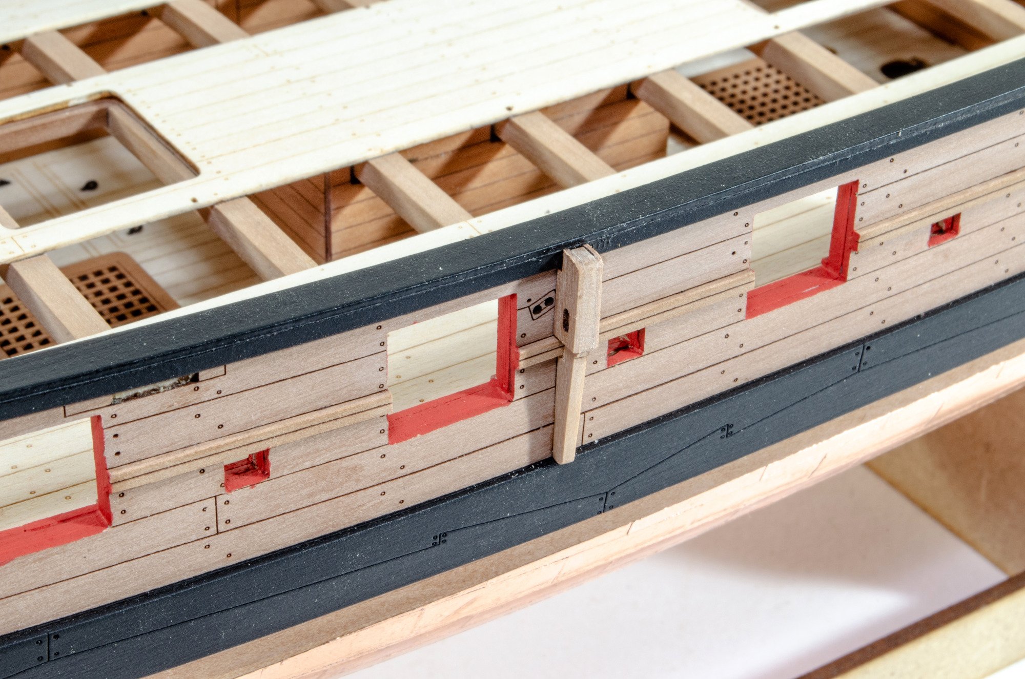
The interior of the hull can now be fitted out, starting with the port eyelets and the bulwark belaying racks and cleats.
The the rudder post box is added, and the small hatchway. Other cleats and parts fitted to the inner stern too.
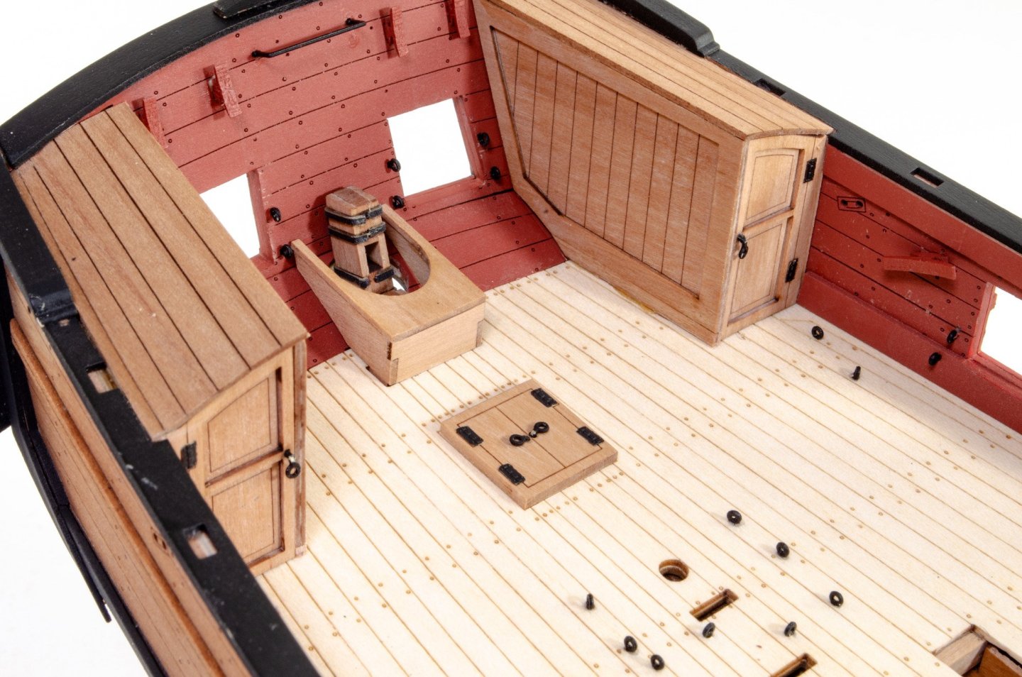
And the bow stage is then fitted.

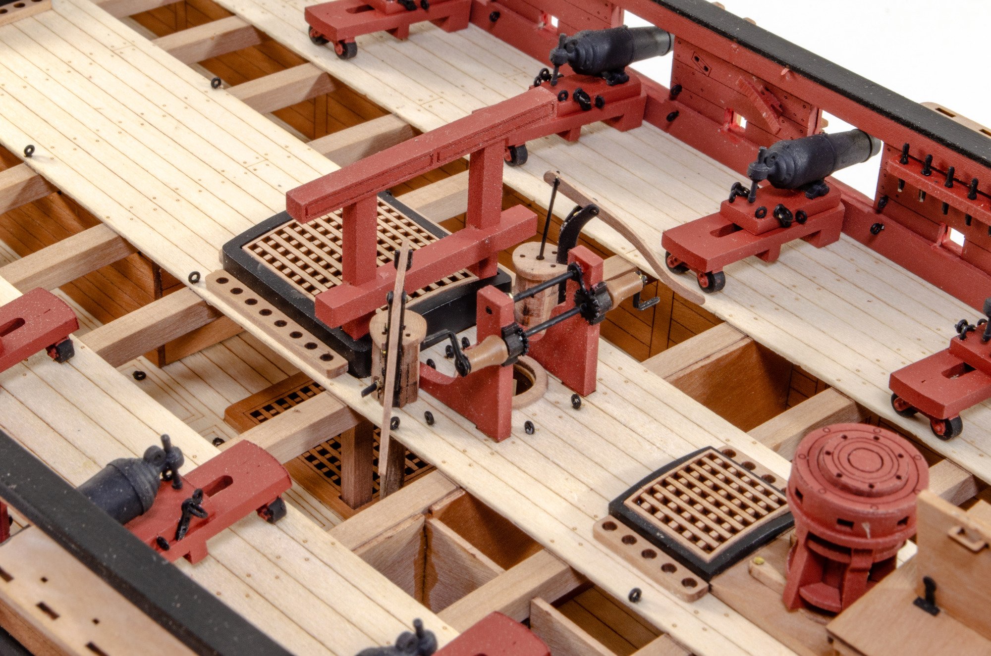
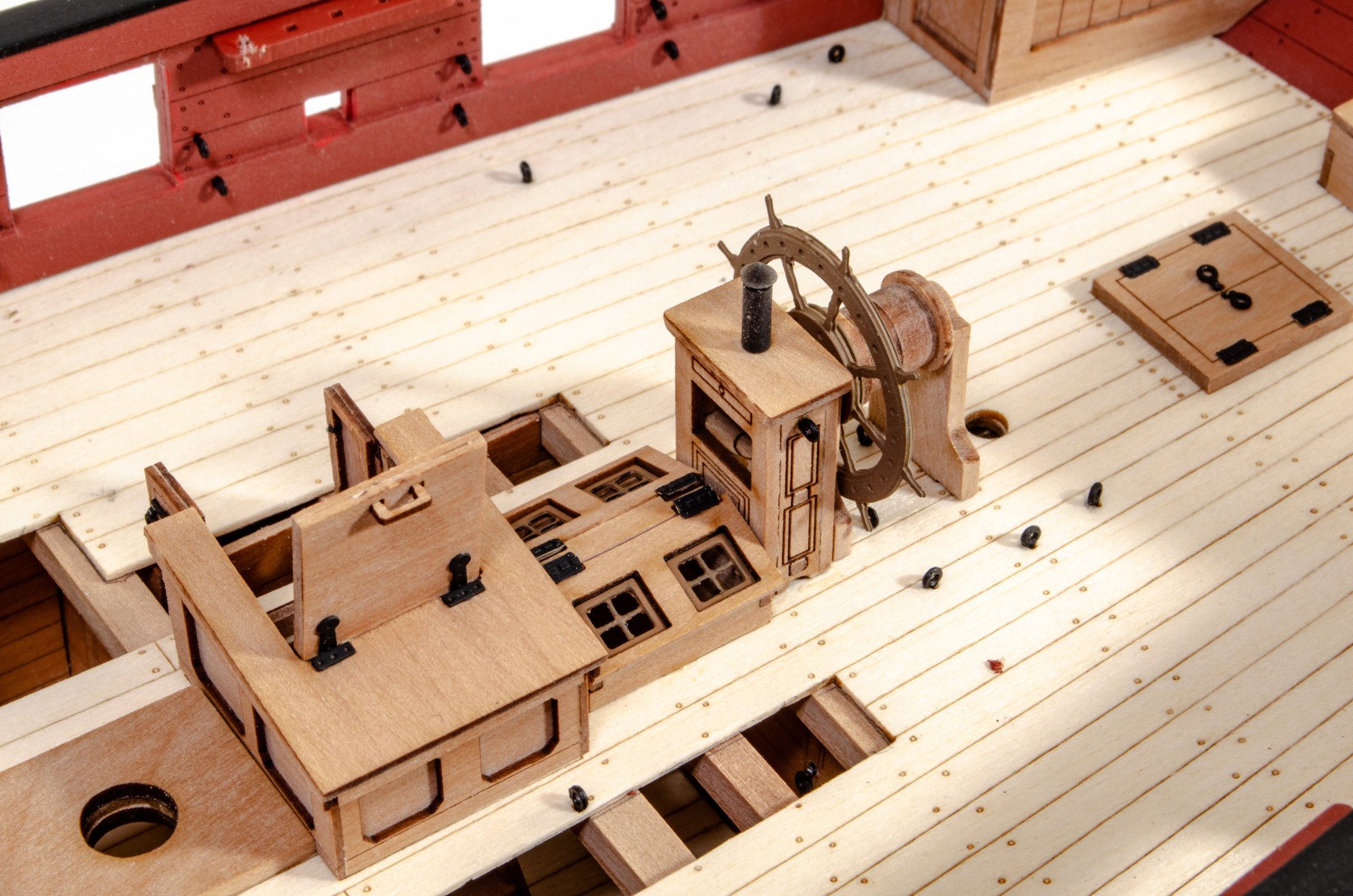
Companionway stars and housing are now added, and the grates are now fitted too.

Both gallows are now glued into place, as are the bitts.

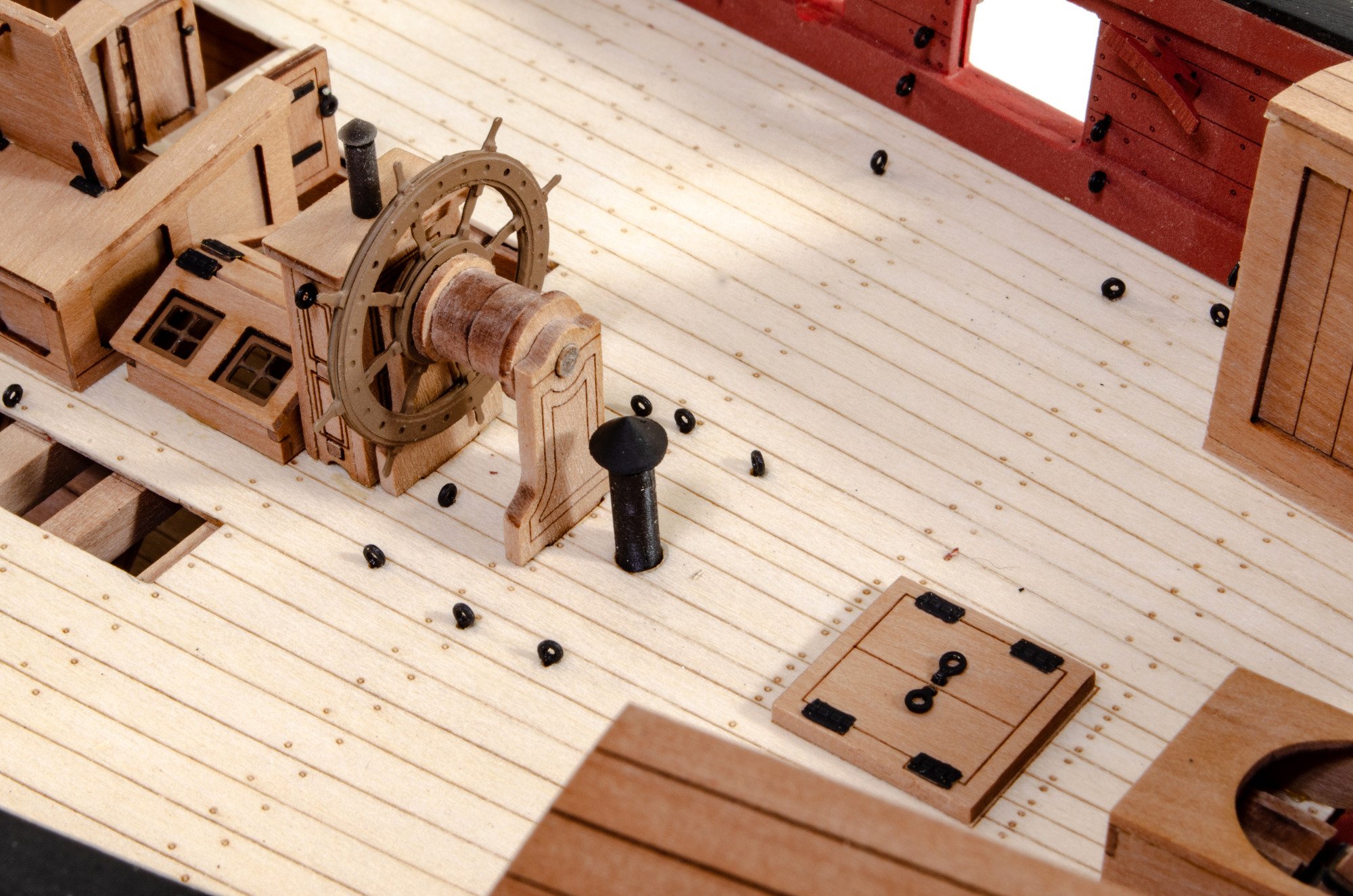
Skylight, binnacle and wheel then glued in.

Ladders also fitted.

More in a moment...
- KentM, ccoyle, chris watton and 20 others
-
23
-
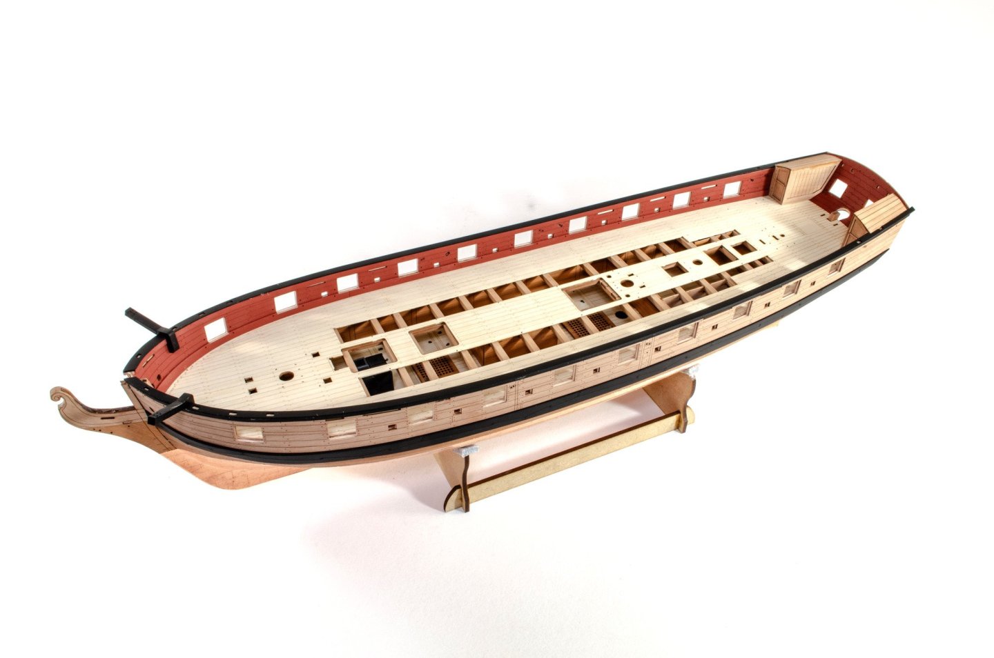
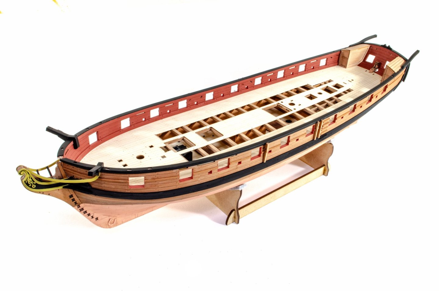
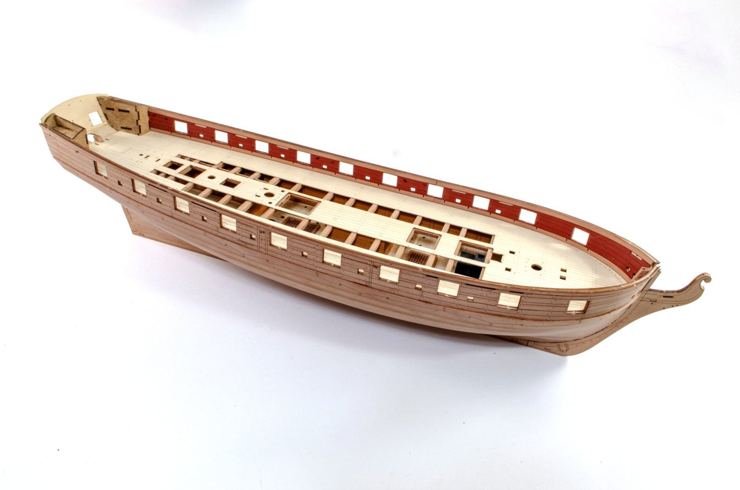
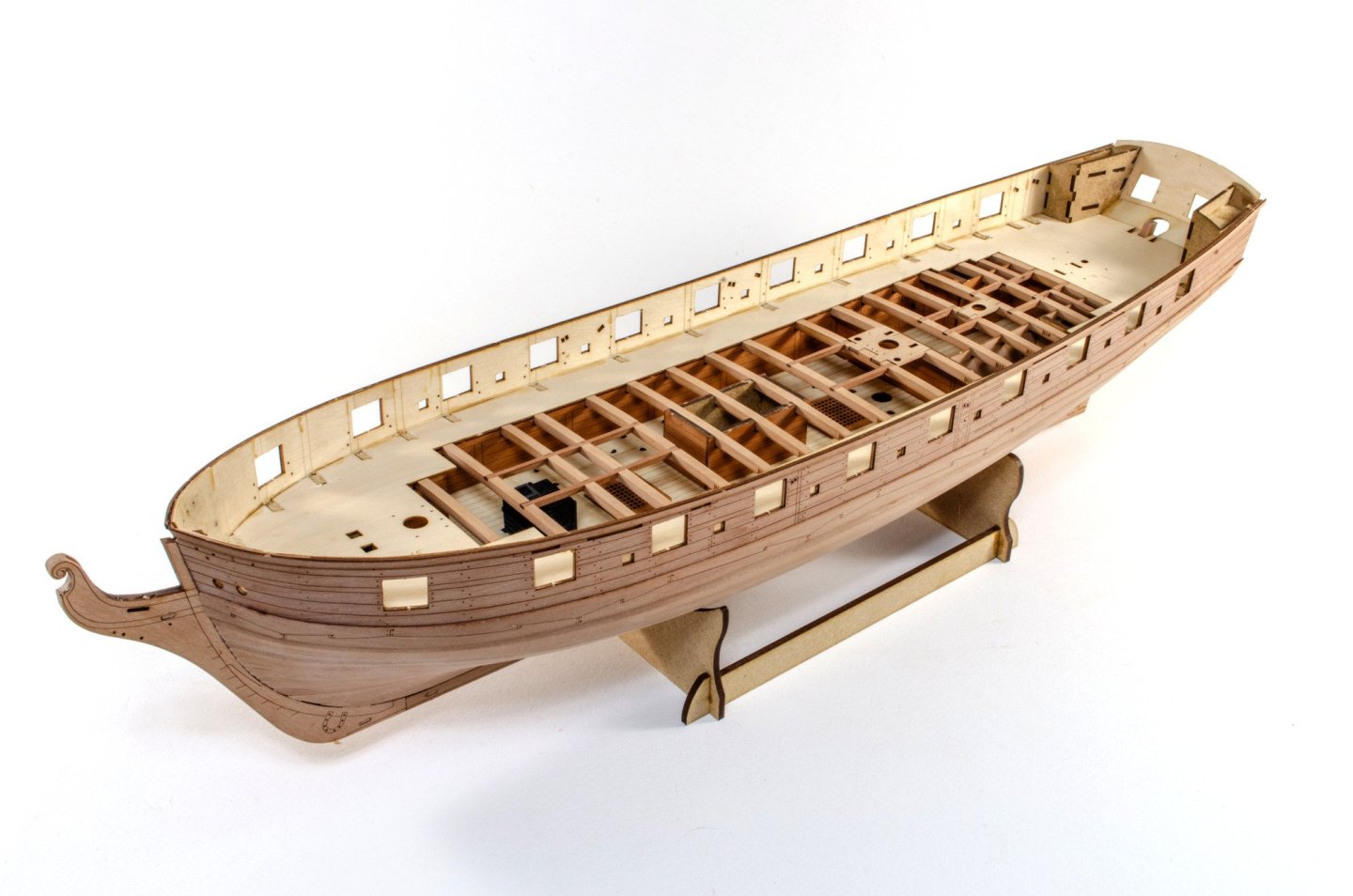
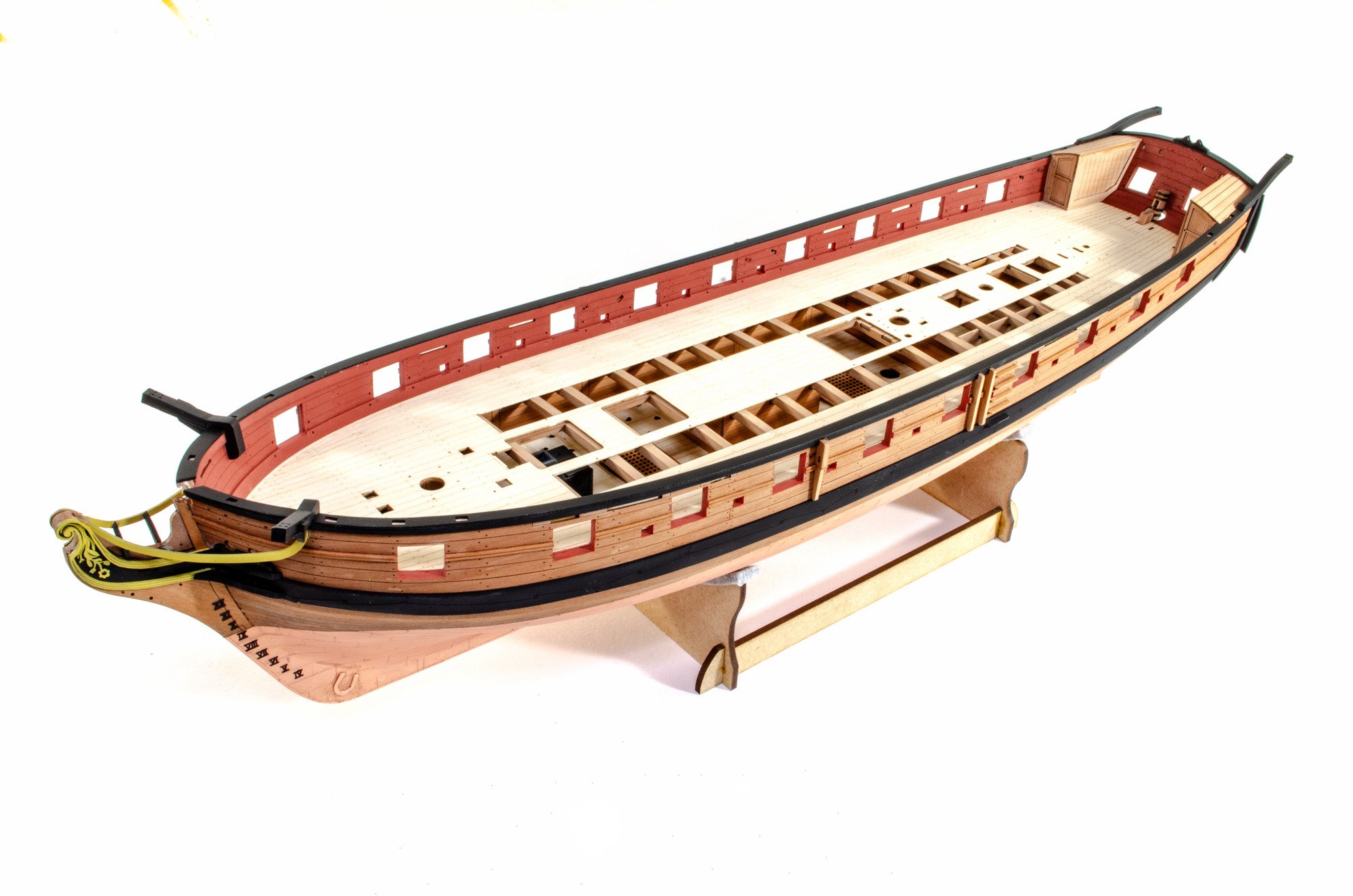
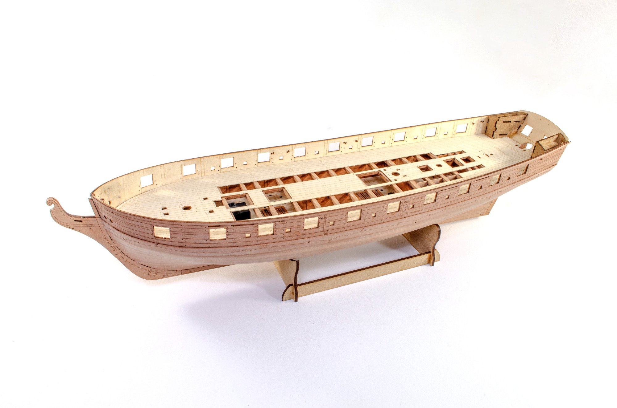
Update time. This more or less takes the hull up to the masting stage.
The stuff that still needs to be done are the chainplates, tiller post and rig, and boomkins.
Here we go...
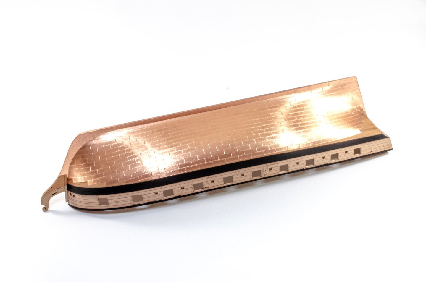
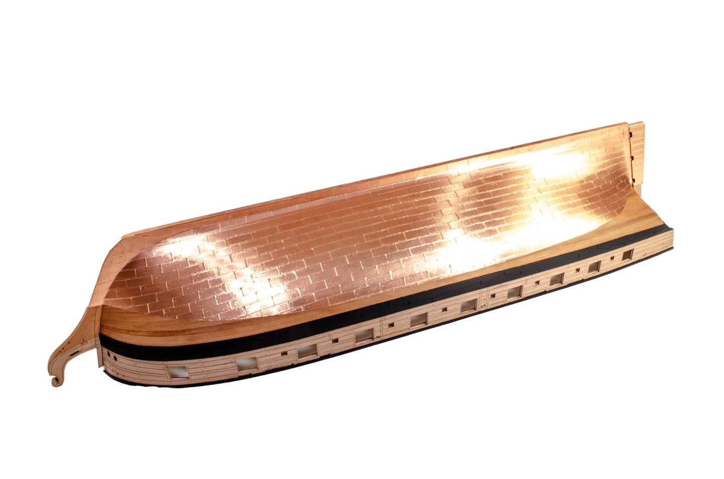
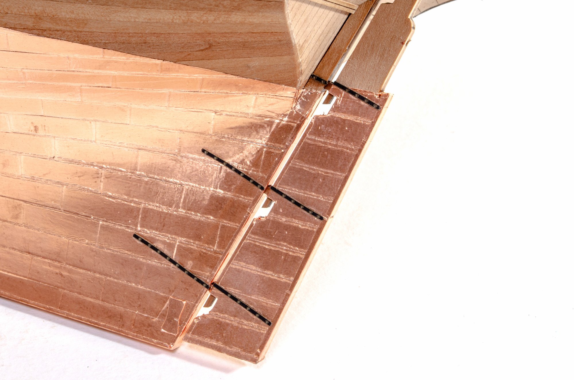
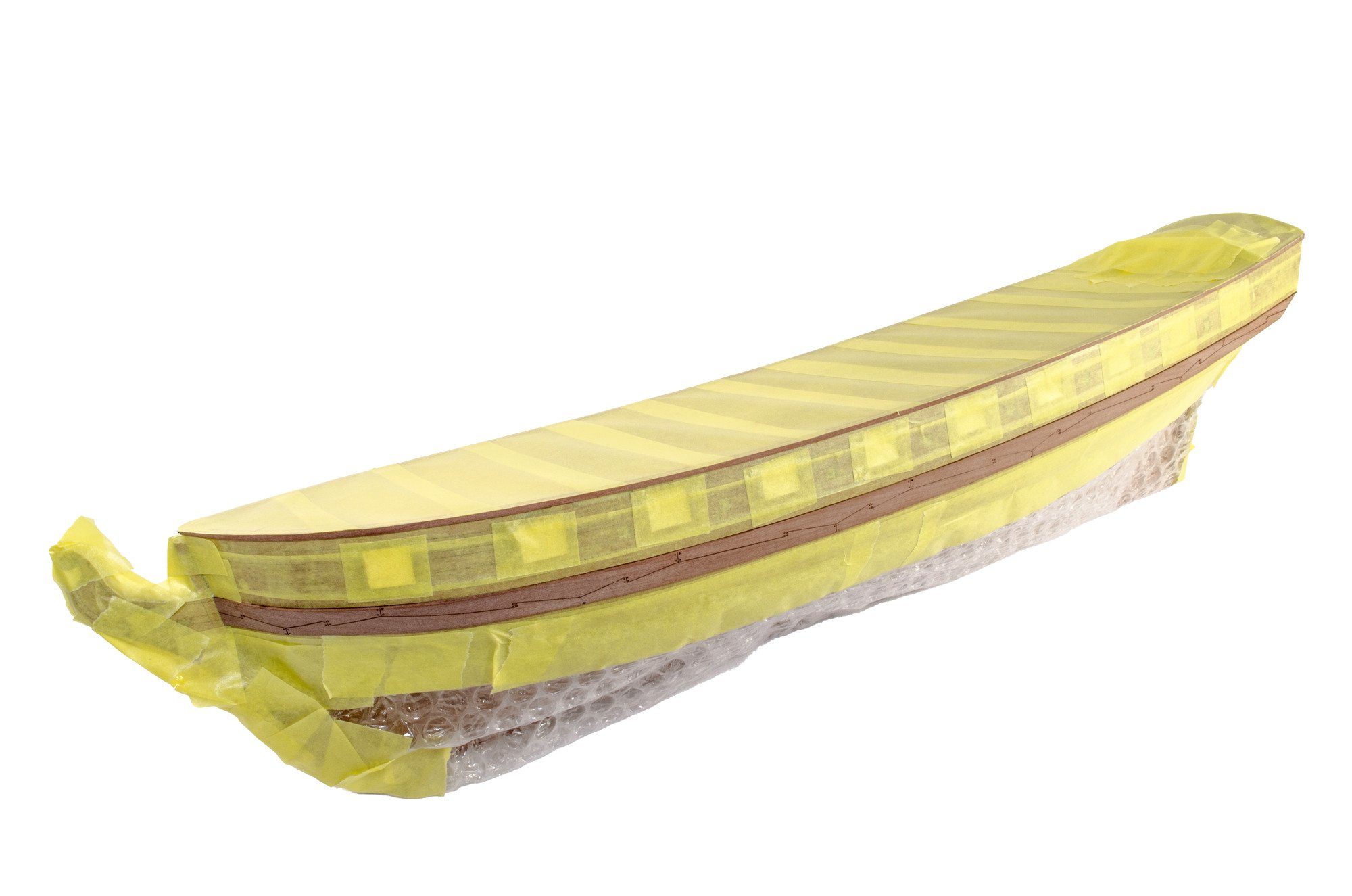
The first task was to ascertain the rough waterline mark and then mask up to it. From there, the hull is filled and sanded back. As this is coppered, the same level of finish isn't required as it would be for a painted hull. The copper tape places are then added and when finished, the whole lot is washed with isopropyl alcohol to remove grease, and then polished with 00000 grade steel wool. It's important to use vinyl/nitrile gloves to stop any grease getting back onto the hull. When done, it's advisable that matt varnish is used to seal everything.
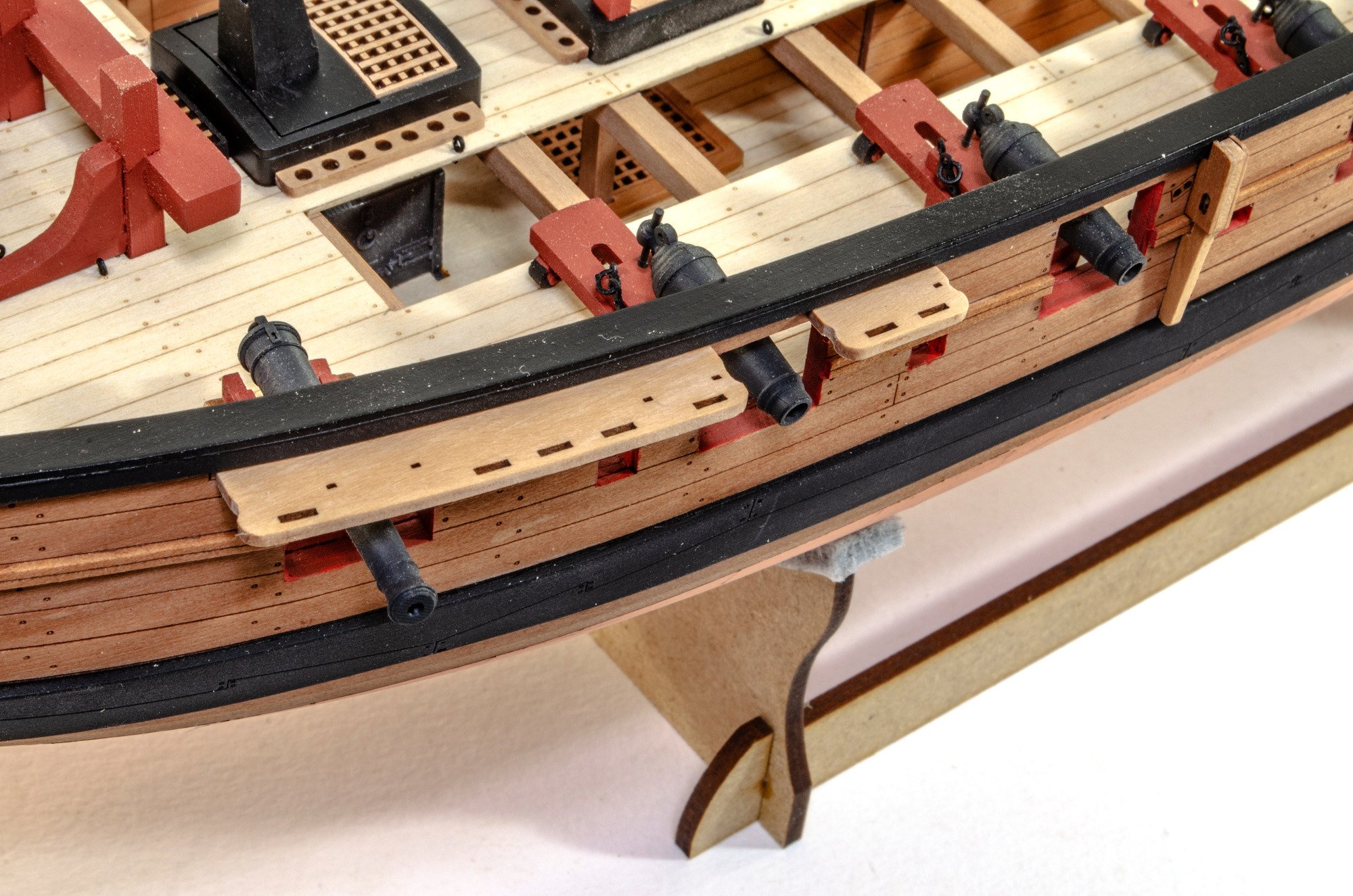
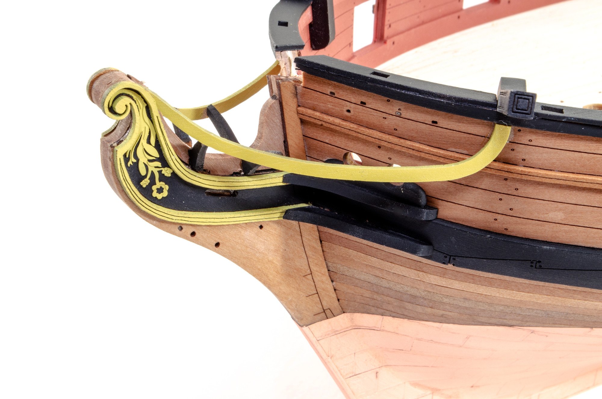
The fore section of the gunwales are added, and then the catheads. The rear portions of the gunwales are then glued into place.
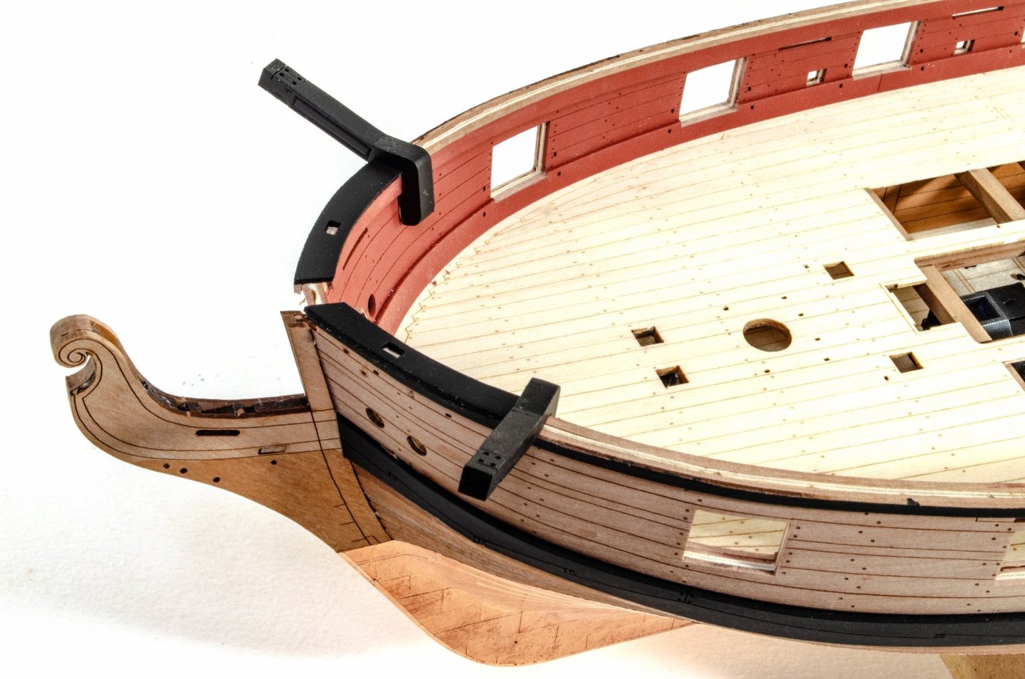
The side rails are added in two sections, with them running across the gun ports. Once set, the obscured gun ports are then cleaned up.
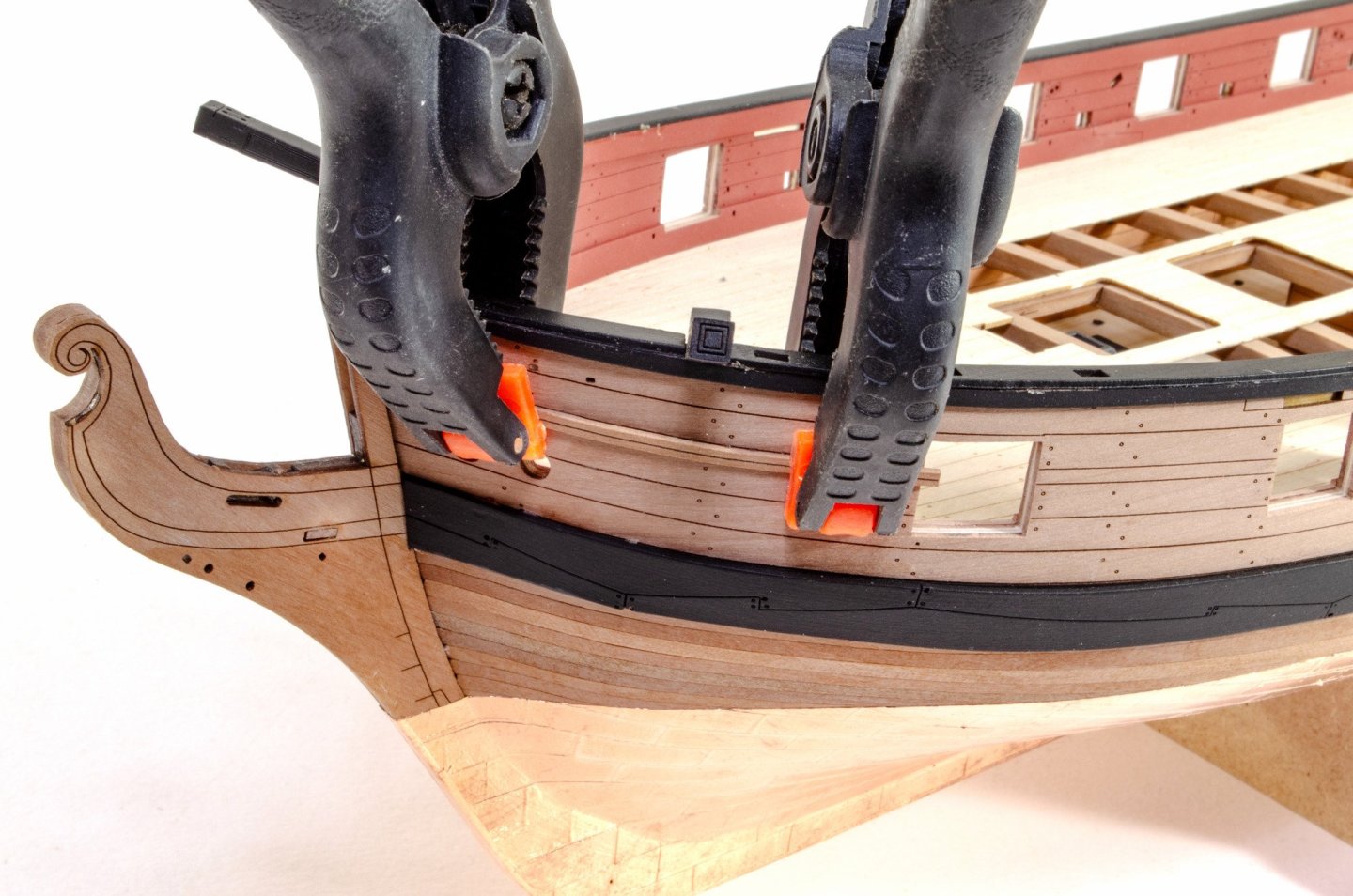

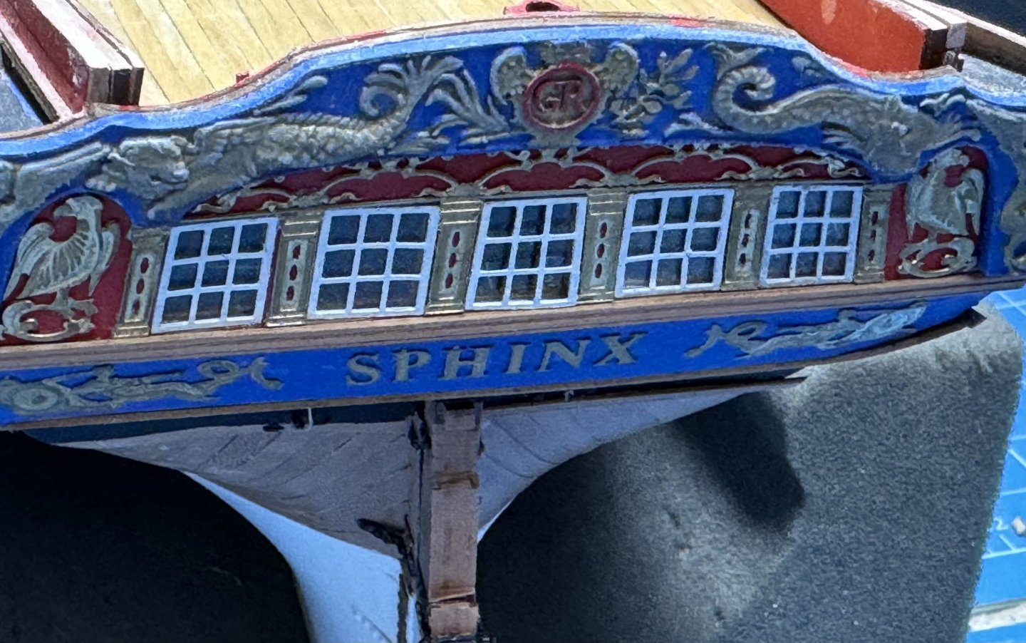
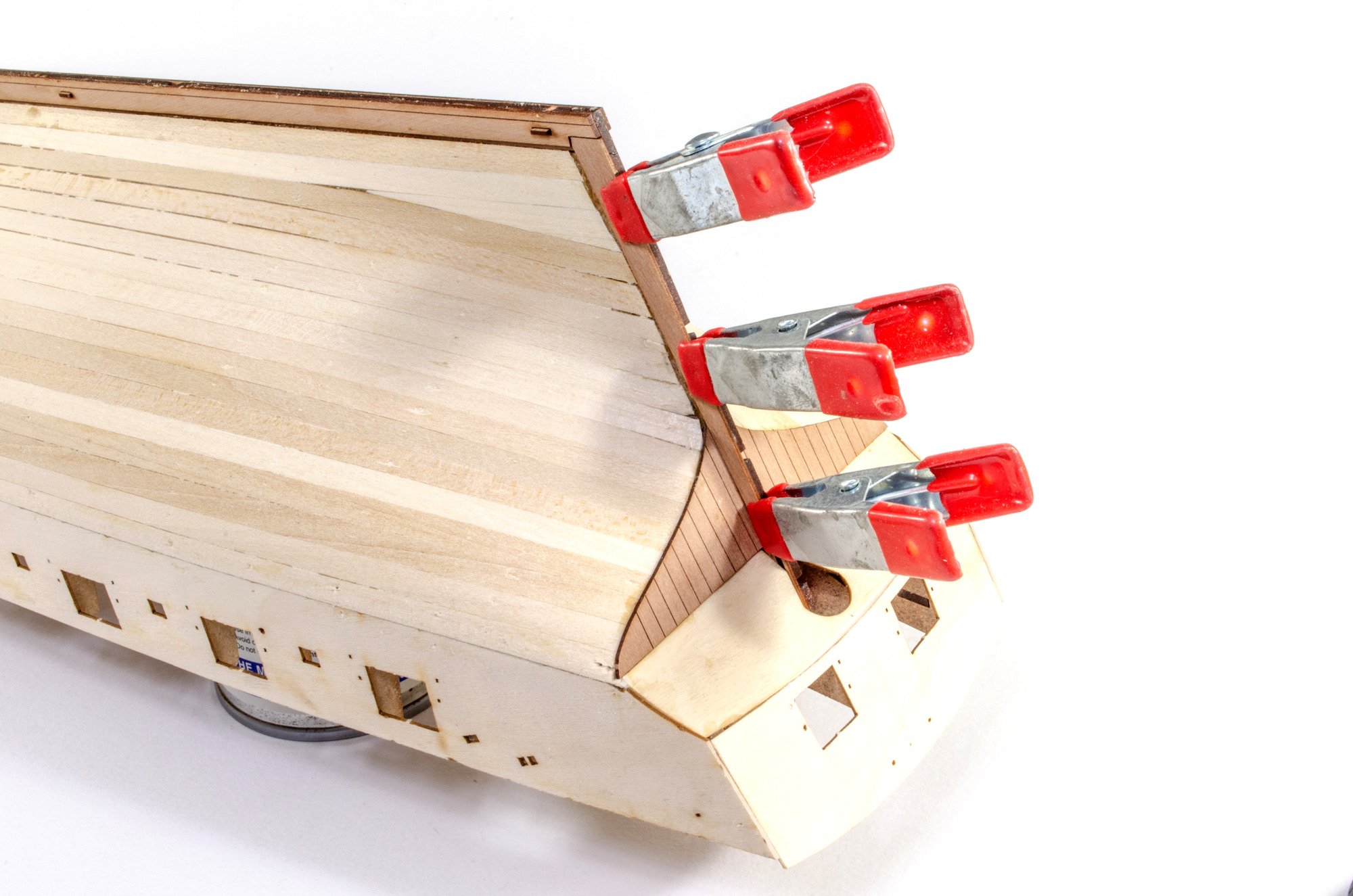
The stern is now assembled and clamped until dry, and the sales finished off at the stern.
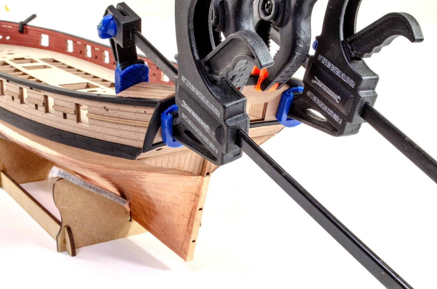
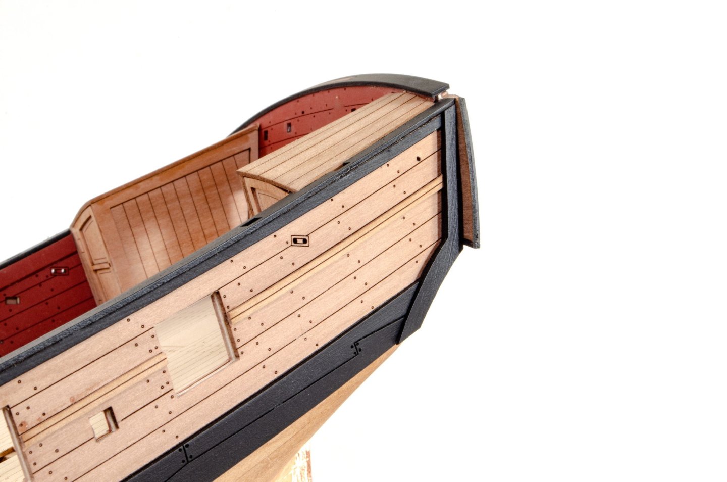
Fenders are now added.
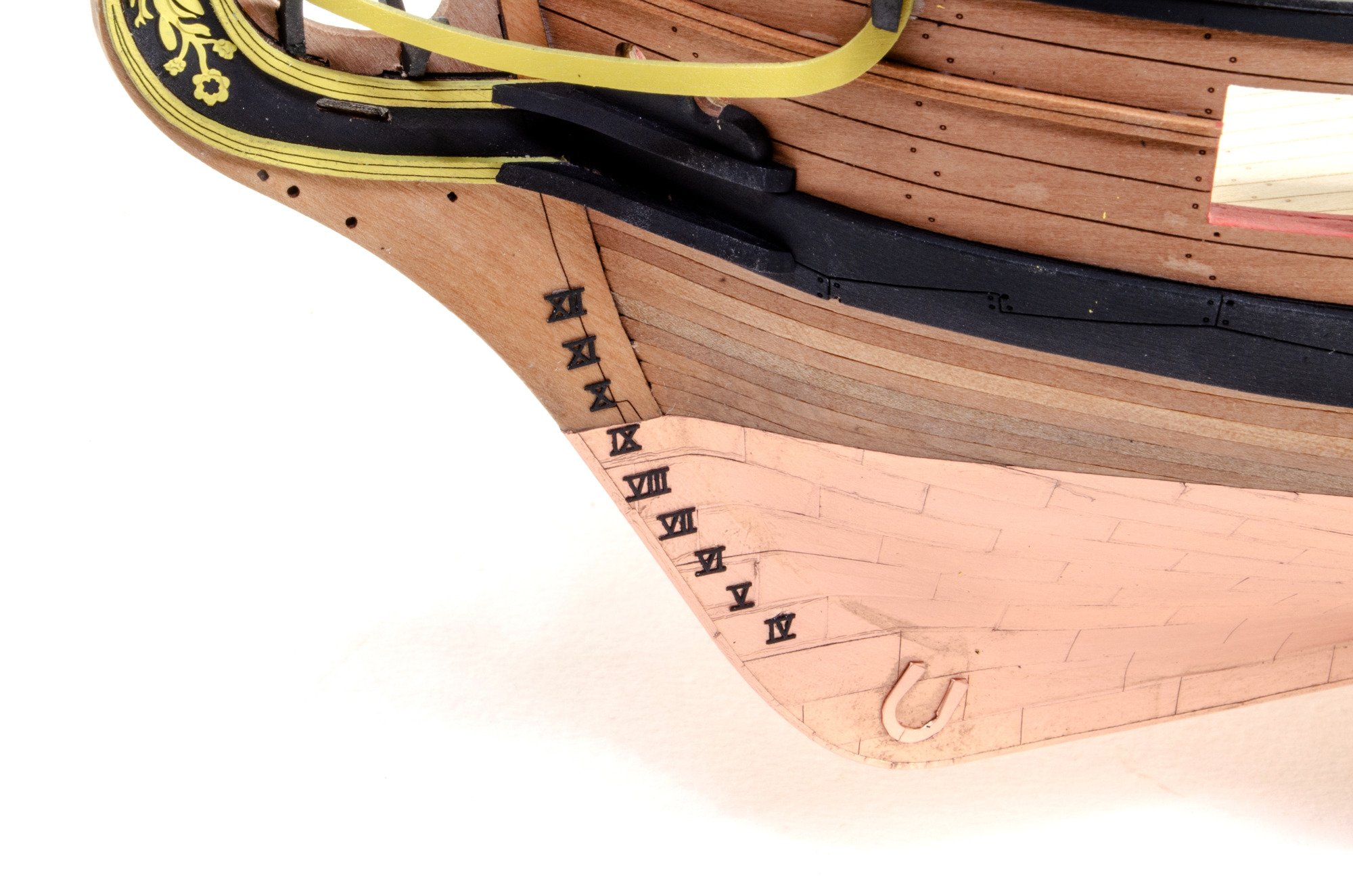
The rudder is now fitted and the hinges fitted.

The head rails are now painted and assembled, and the depth markings painted and added.


-
On 9/2/2024 at 1:17 AM, cdrusn89 said:
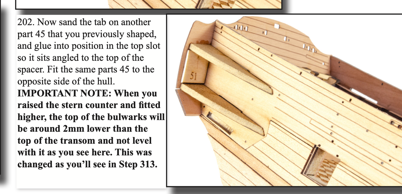
It appears that now the entire stern is too low. I am not sure how these are all supposed to fit together (I better make an exhaustive search of the supplemental drawings - the instruction manual is pretty light on this (IMHO)).
Here is the stern now.
The bulwarks stick up about 4mm (at least it is the same on both sides).
There is additional information in the manual regarding setting the height of the stern parts so they sit above the bulwarks.
Page 38
-
....continued.
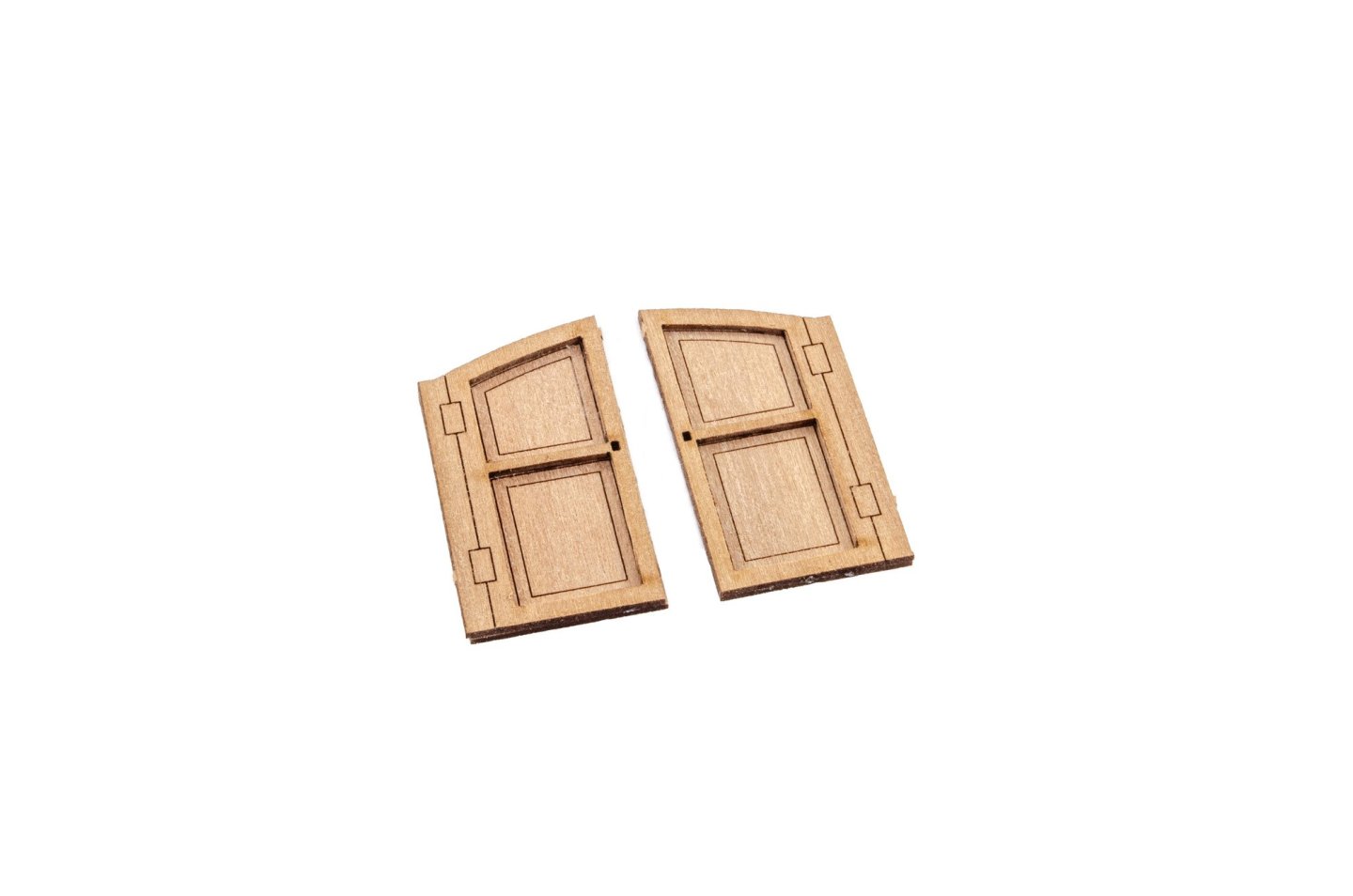
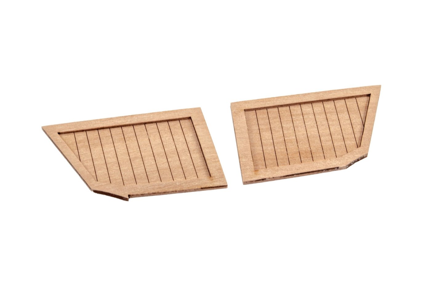
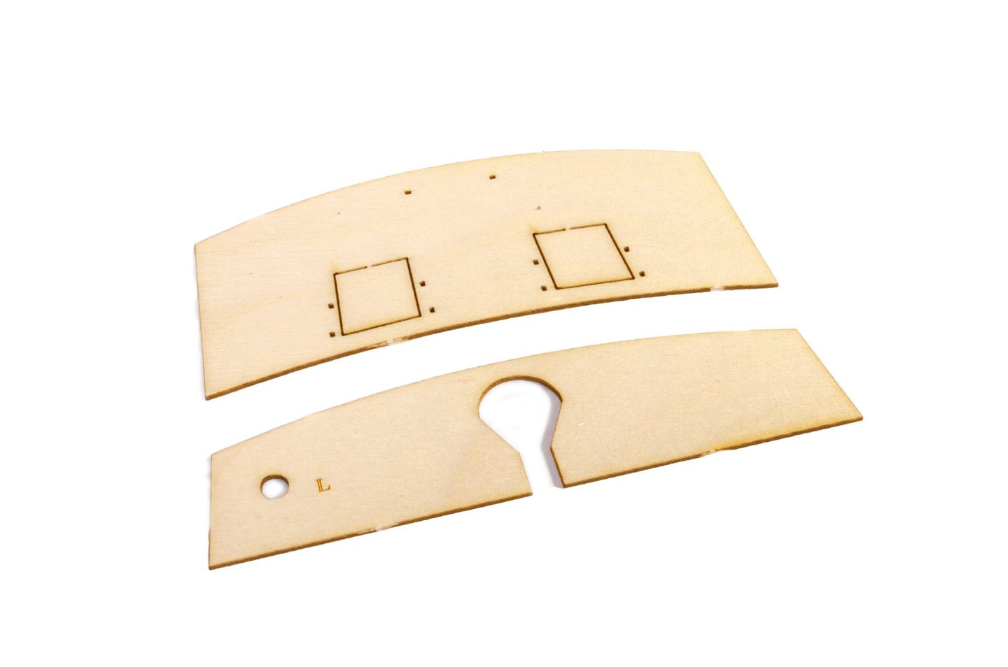
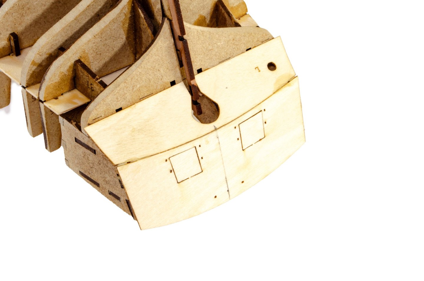
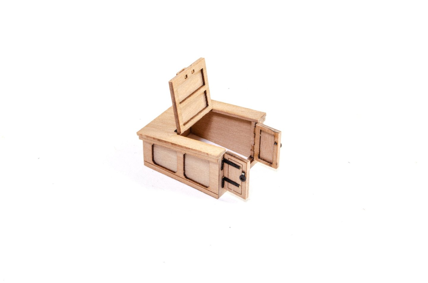
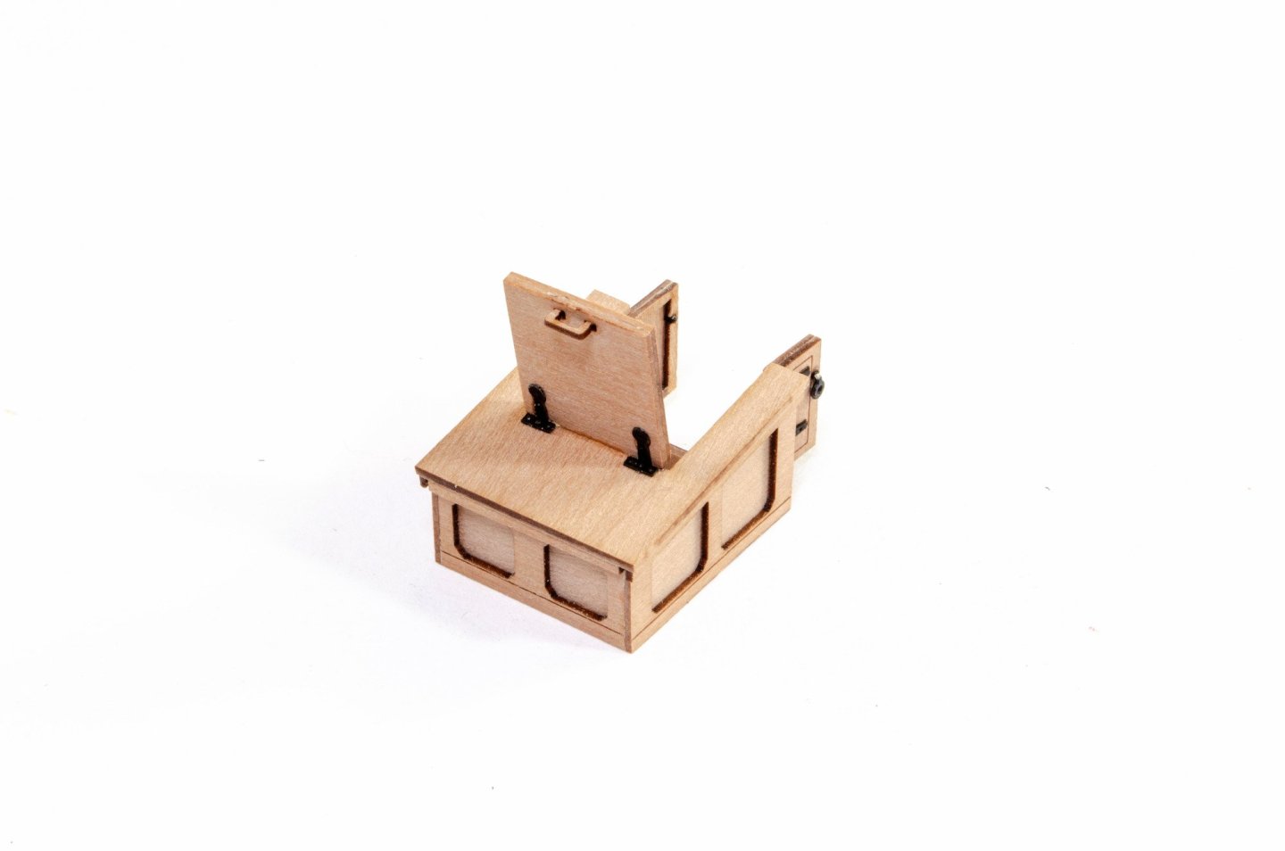
The cabin/latrine doors are now built, along with the cabin sides. These are then glued into place.
Each spirketting length is also supplied in halves. The forward ones are fitted first, after pre-painting.

....now the ledges. These are full length strips.

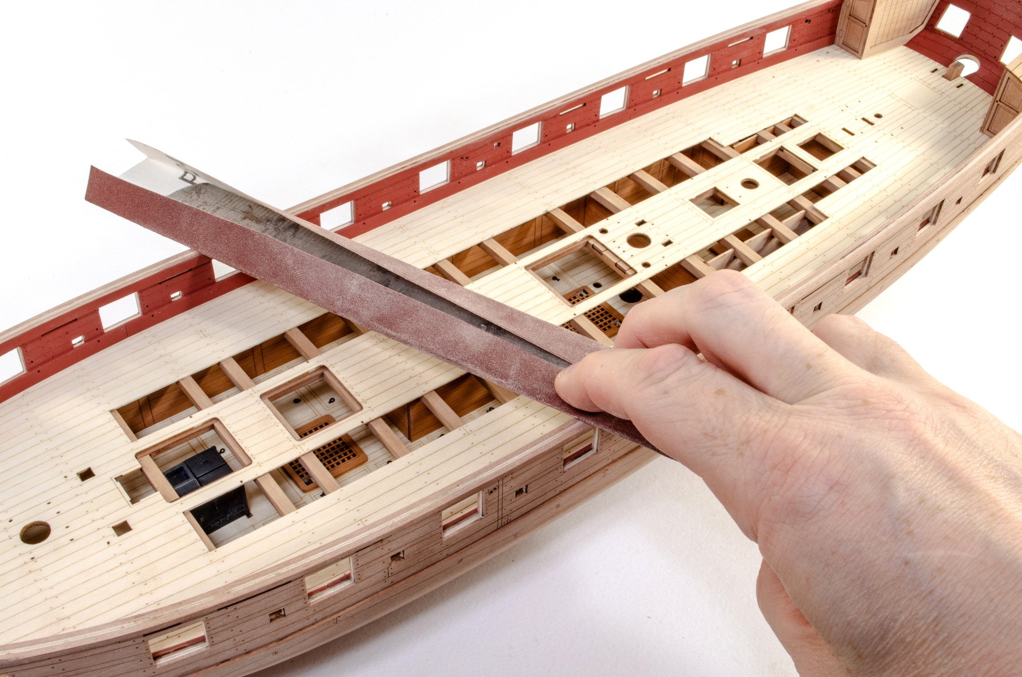
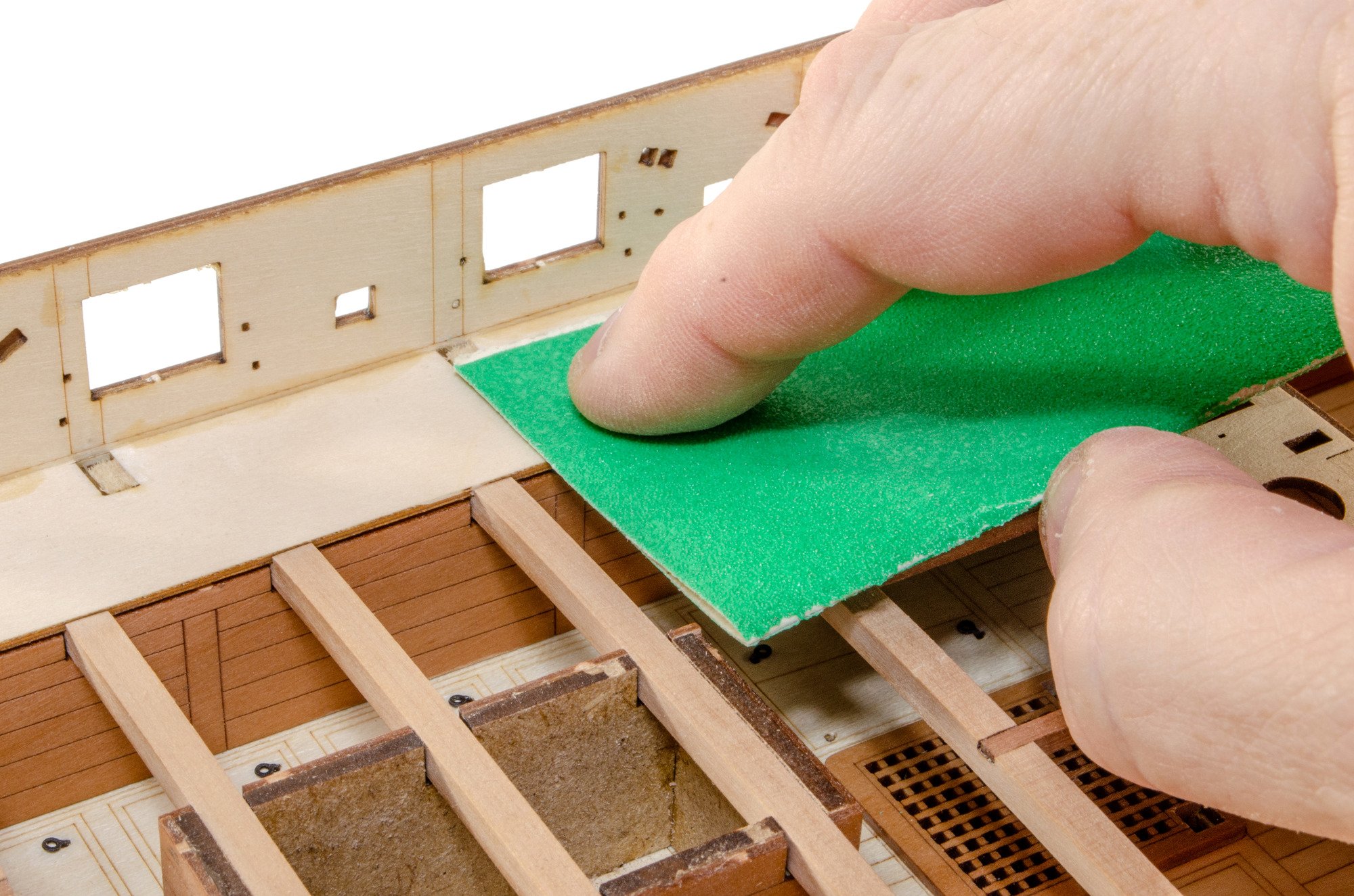
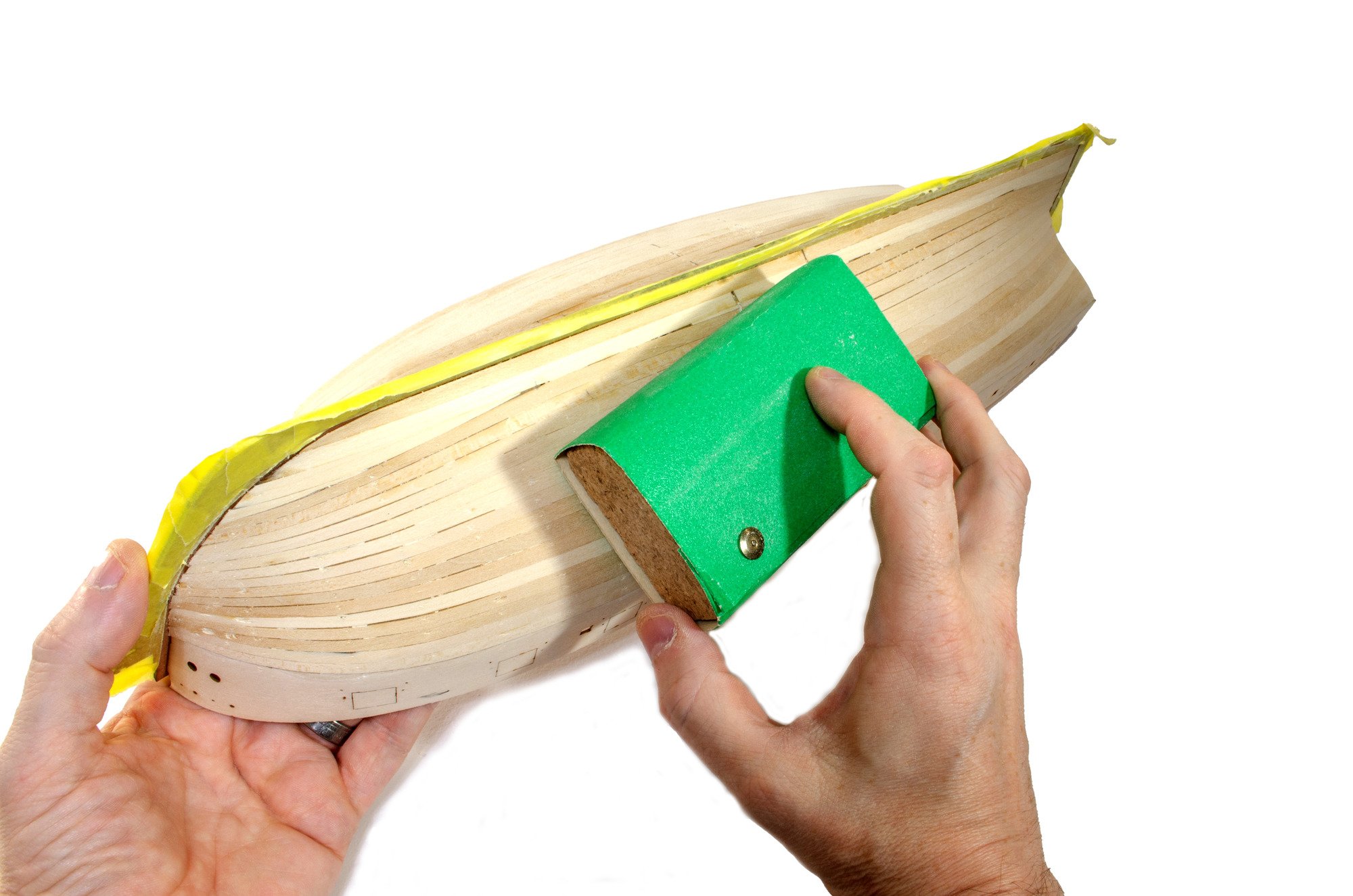
With basic hull work complete, I use a 12-inch steel rule, wrapped in sandpaper, and draw it evenly over the tops of the bulwarks, levelling them.

The hull is then masked before the top rail and wales are painted black. For the prototype, I use Games Workshop's 'Chaos Black' as it has an amazing coating ability. This is from an aerosol can, hence the silly amount of masking you see!


More next time.
- SiriusVoyager, brunnels, thibaultron and 28 others
-
26
-
 5
5
-
...continued.
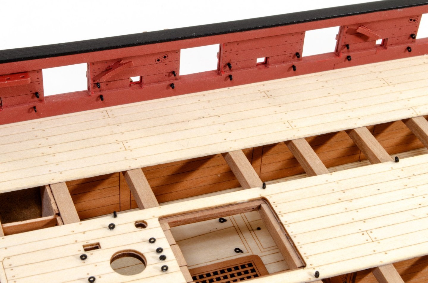
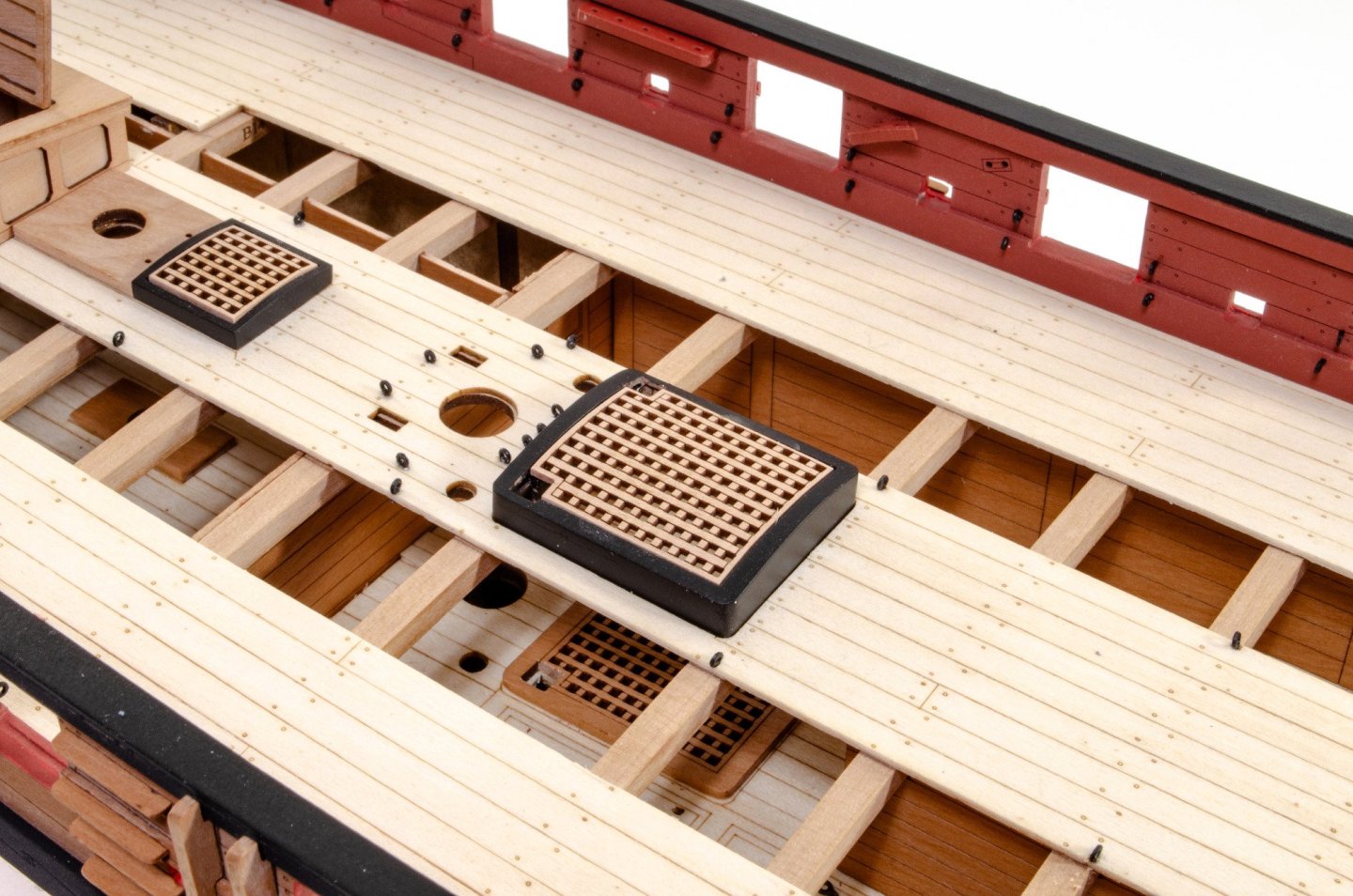
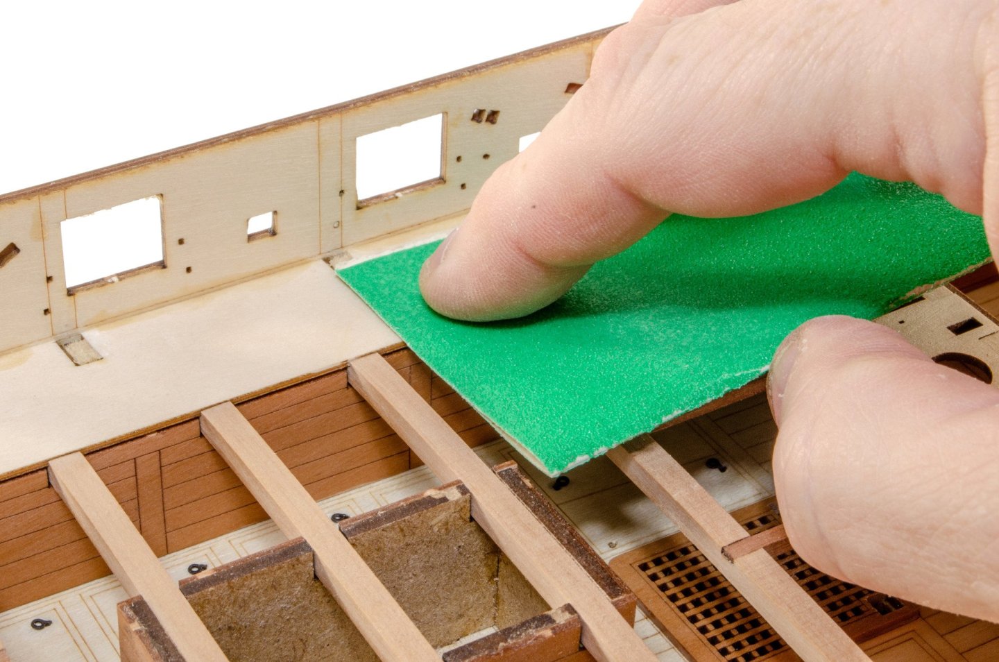
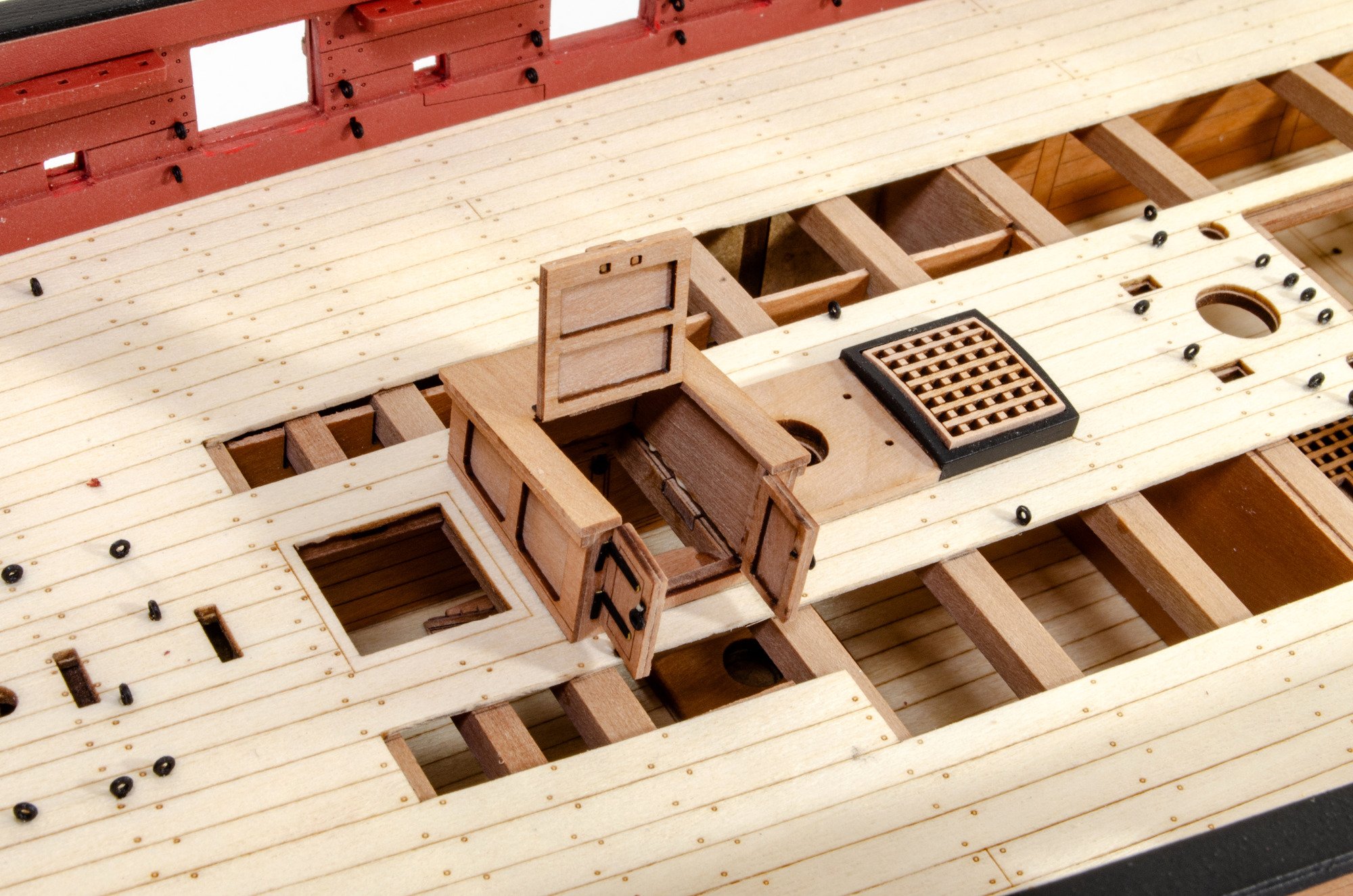
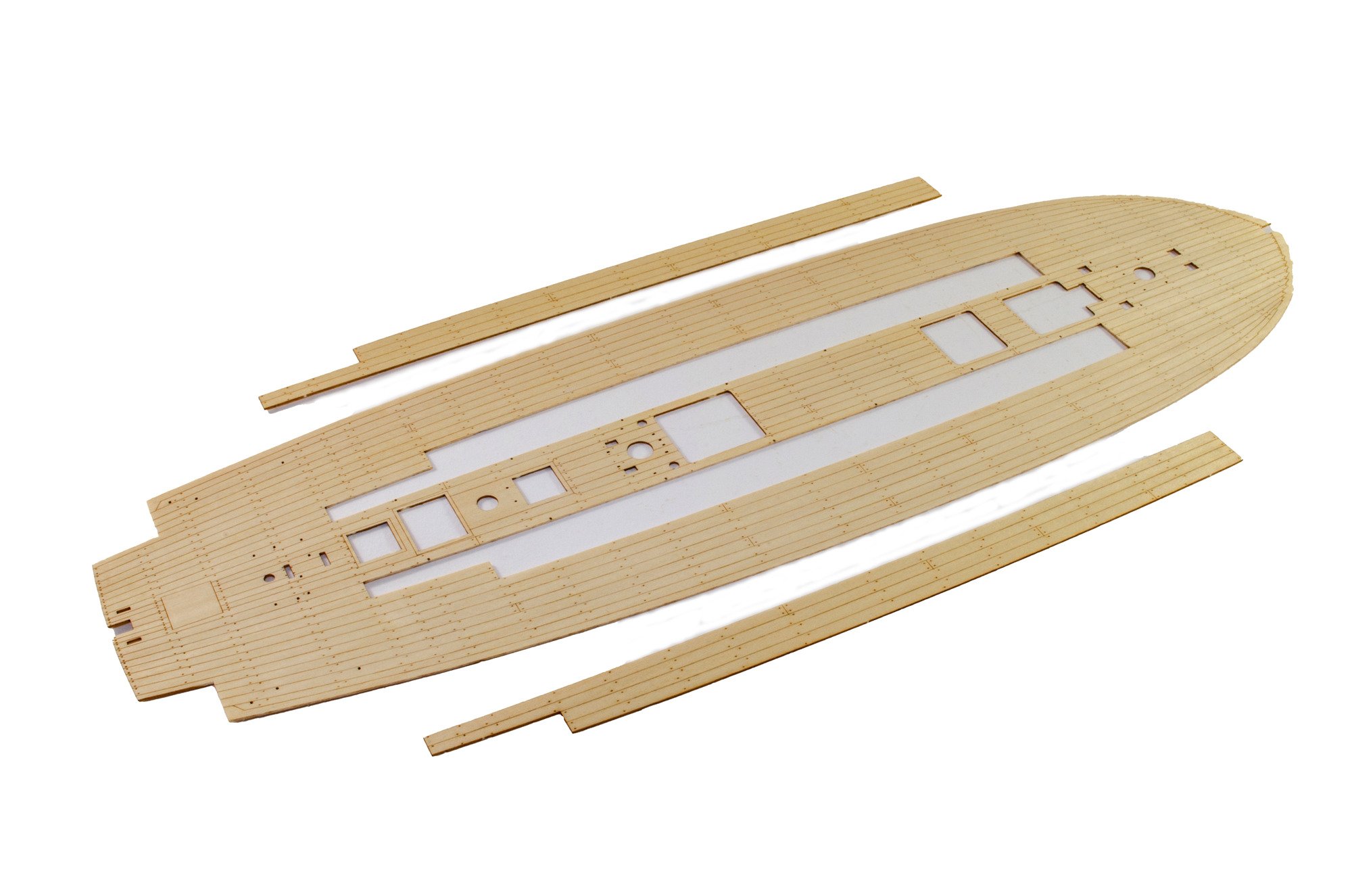
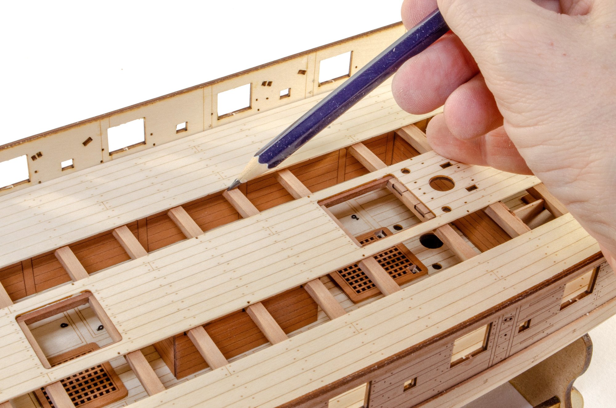
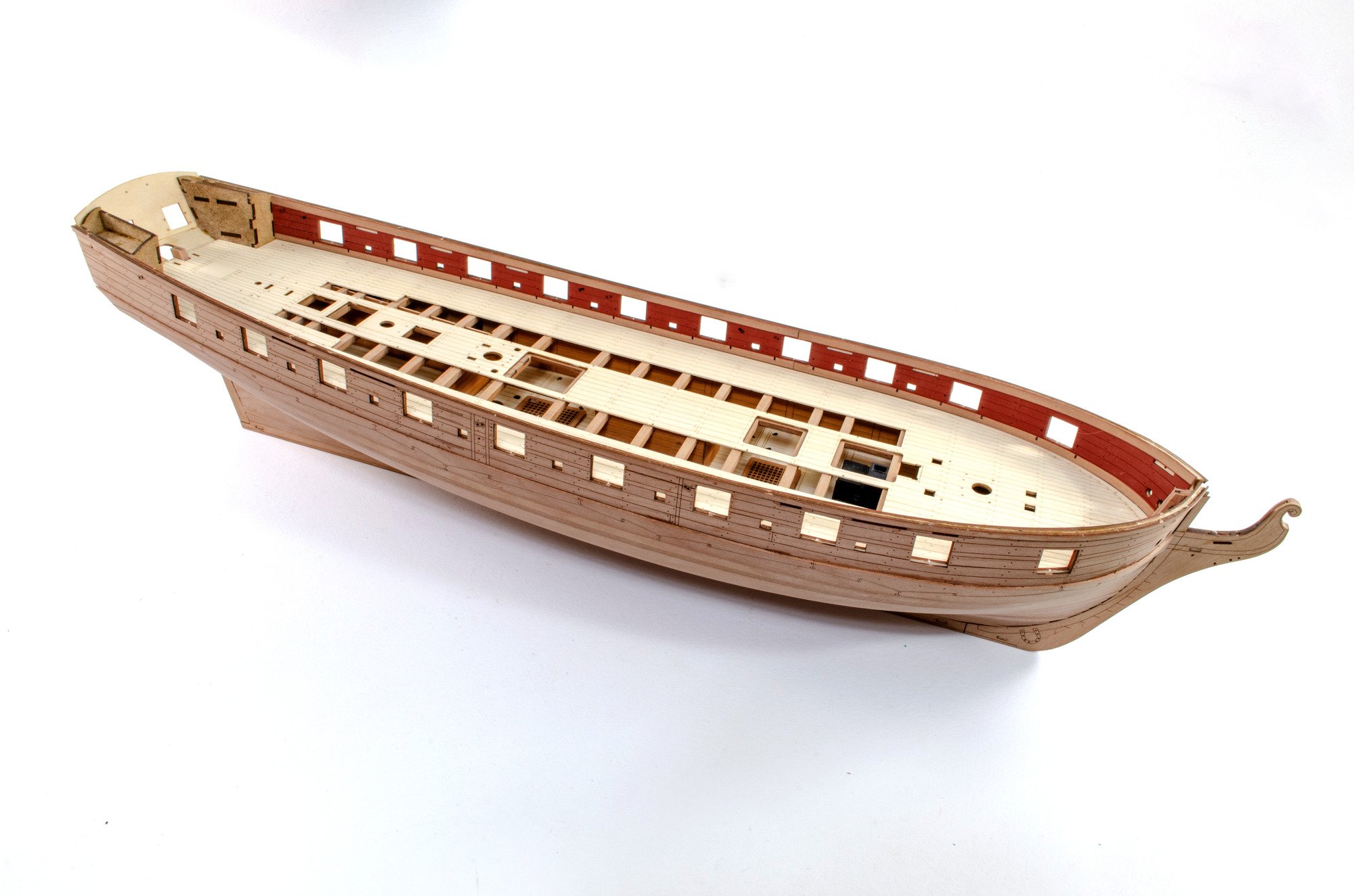
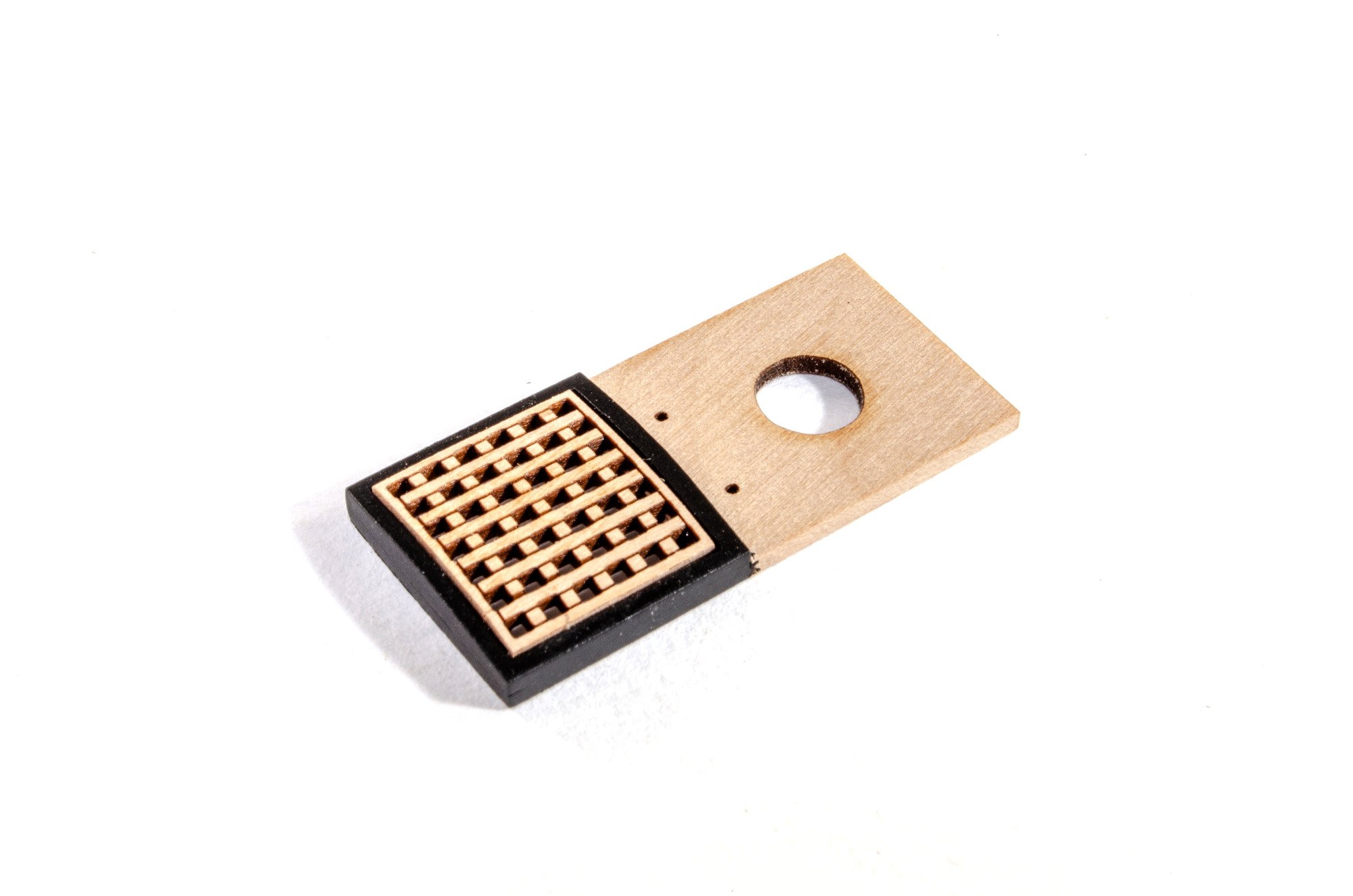
Time for the laser engraved deck to be fitted. As you can see, the cut-outs can be left in place if you don't want to see below deck. The areas on the main deck denote the areas that need to be removed from the deck.

After test fitting, the deck is temporarily laid in place so I can mark the edges of the cutouts. This is to stop me putting glue in the exposed areas. On my build, the deck needed no adjustment whatsoever and fit the first time.

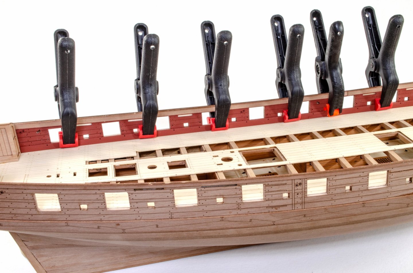
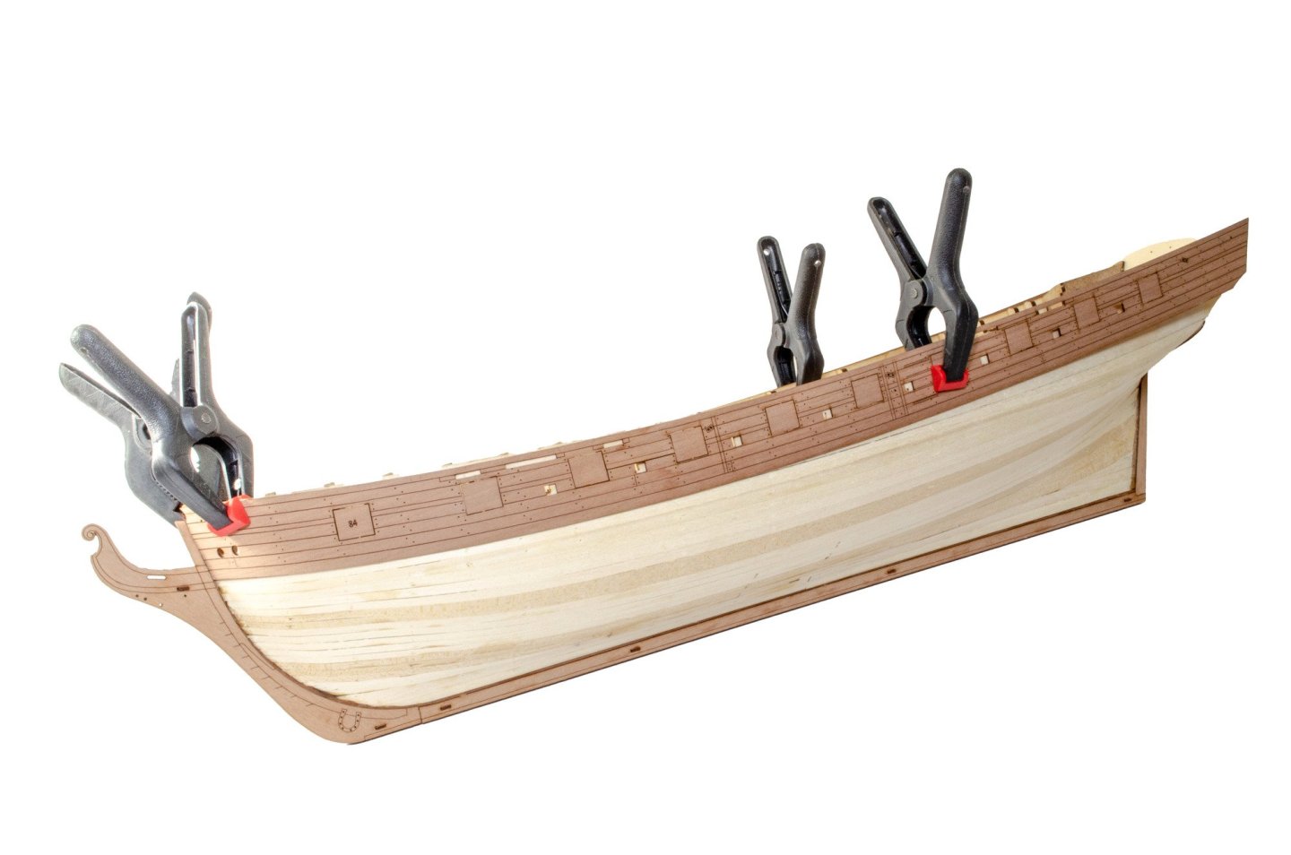
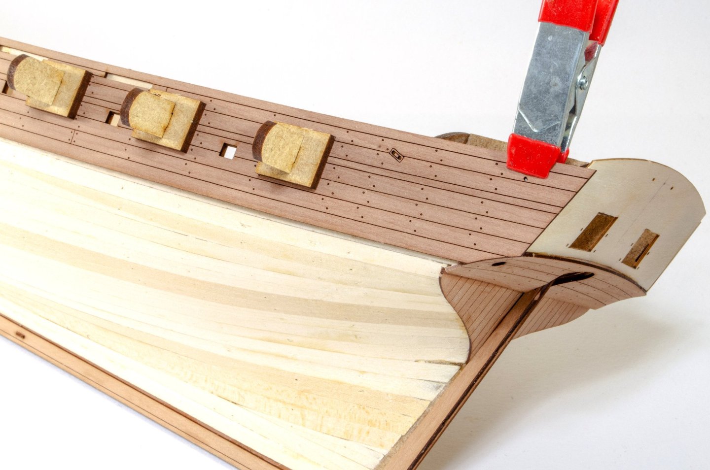
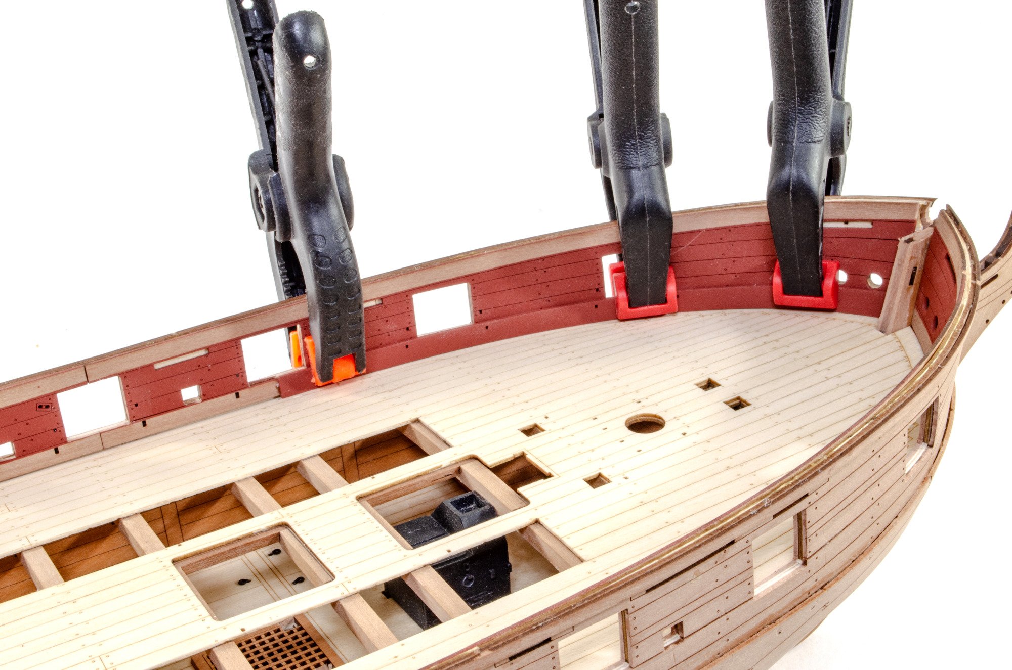
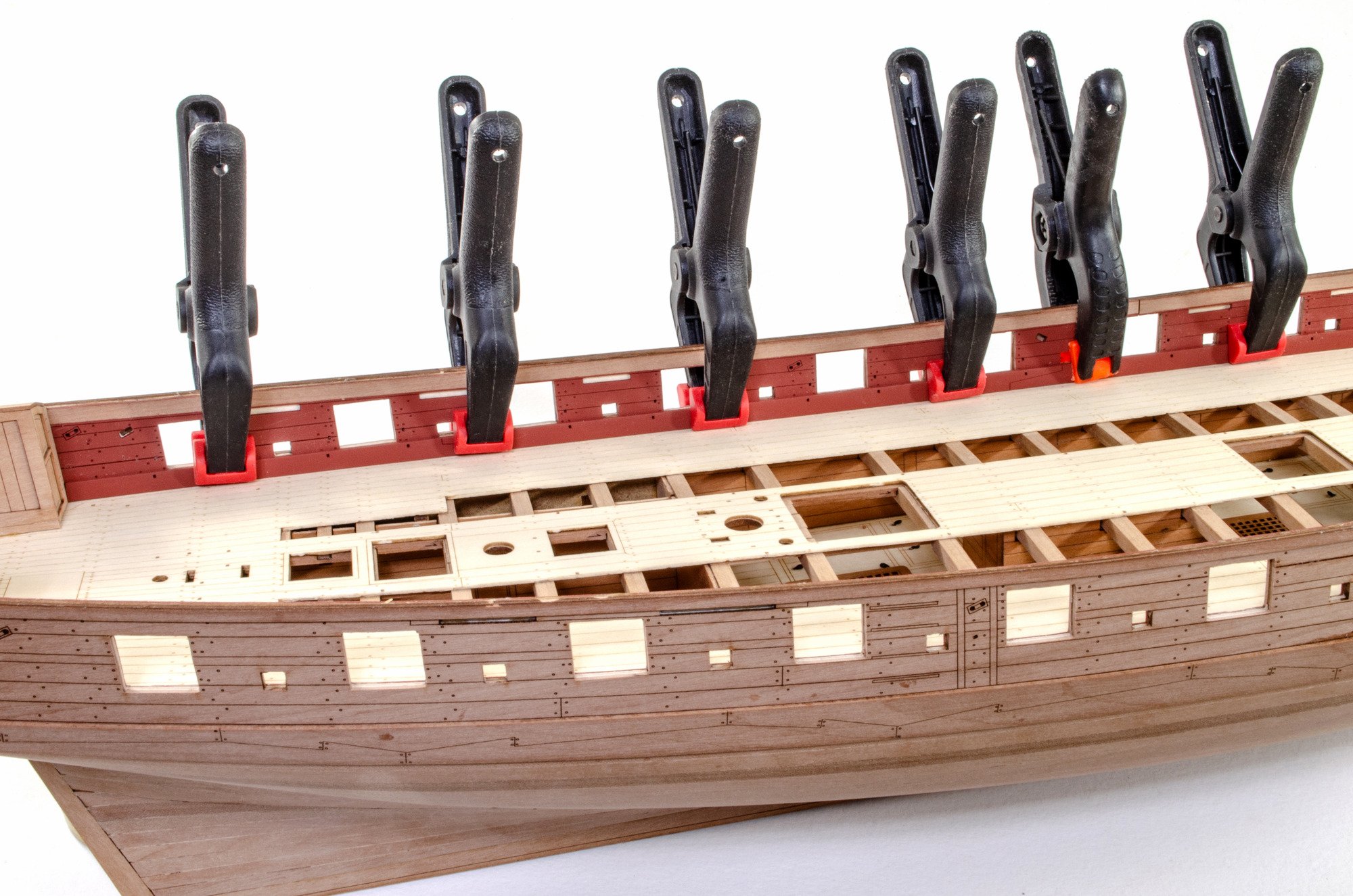
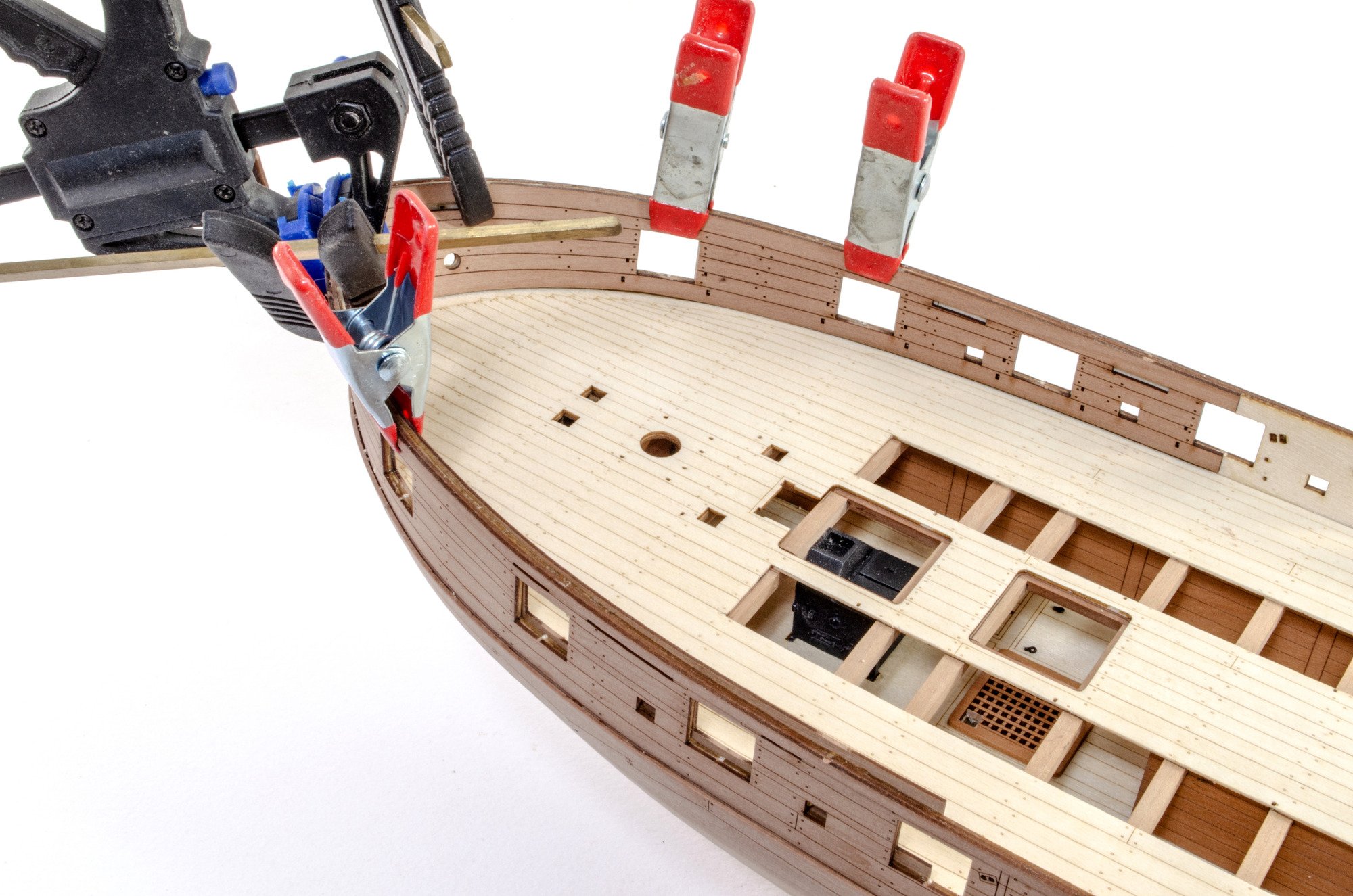
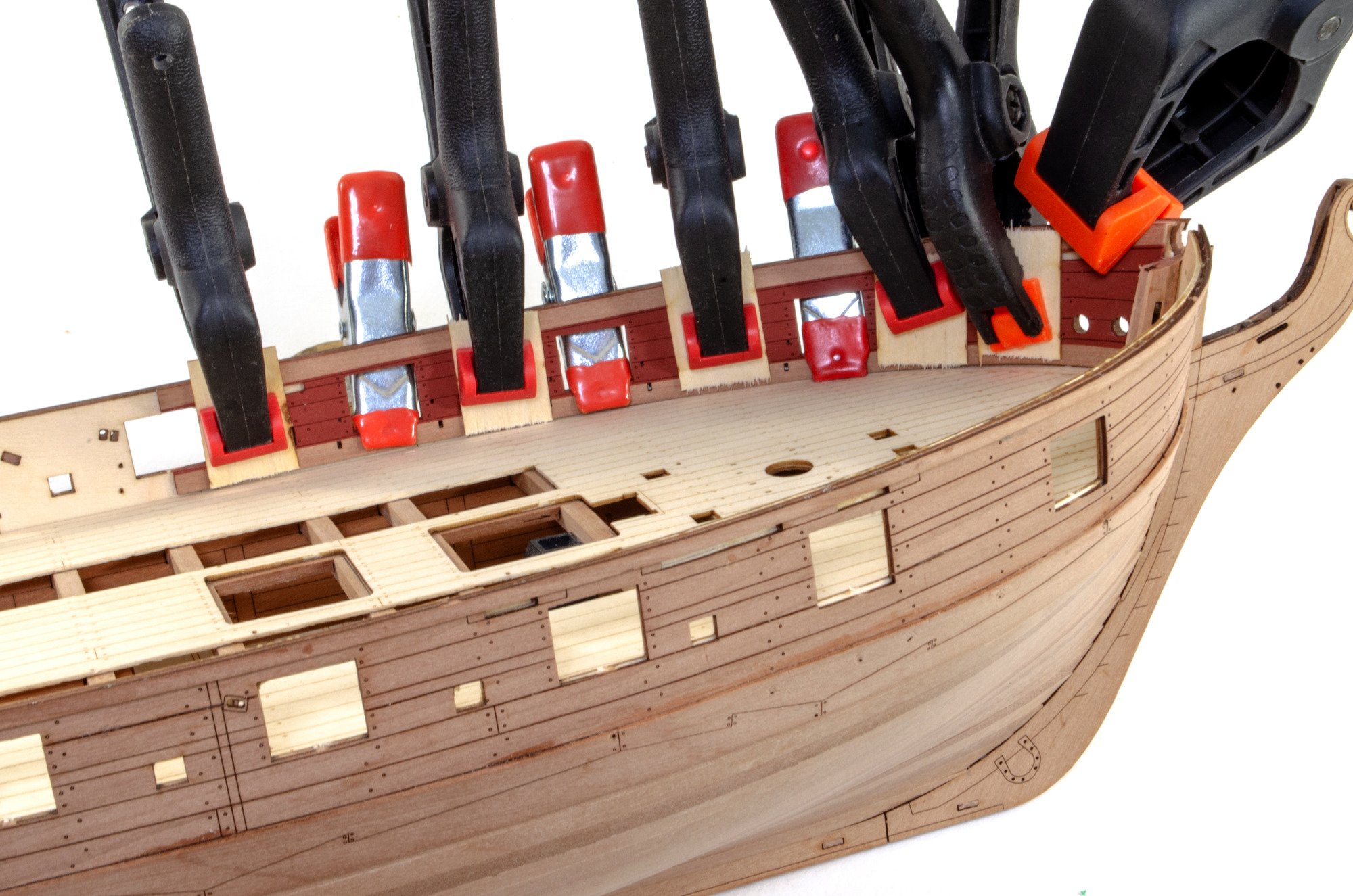
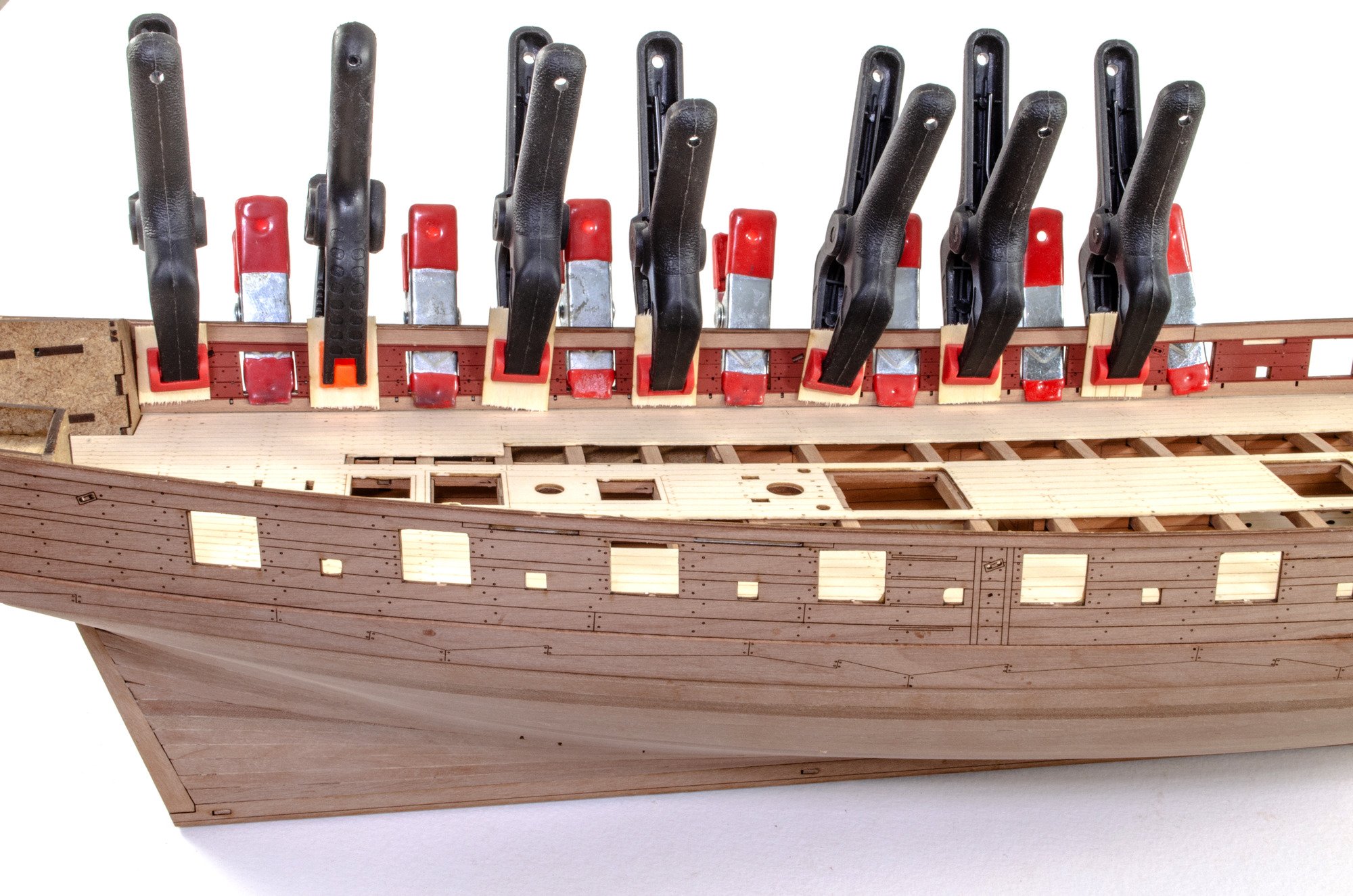
The deck is now glued into place and a few clamps applied. The 20inch clamps are great for going through gun ports and holding the deck edges in position.

Each inner bulwark is provided as two parts. The fore goes in first. It's easy enough to paint these before fitting. What I did do with the fore parts was to clamp them in place first, with no glue. I left them 24hrs so the fibres relaxed a little, making it easier to glue and clamp later.


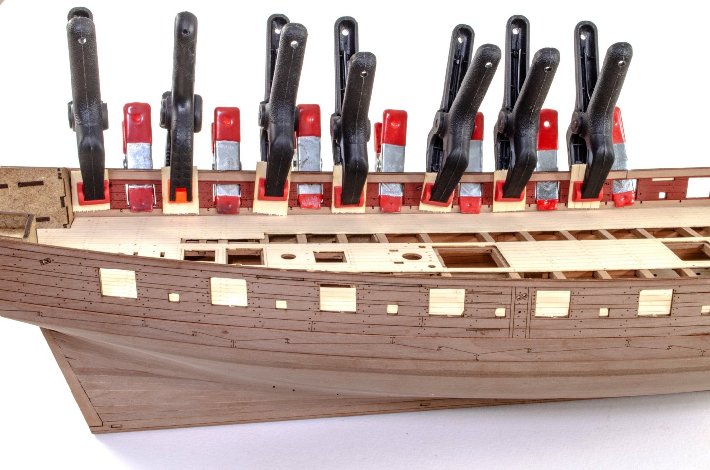
You can see how I left paint from the areas where the spirket and ledge will fit.
Before I can fit the spirketting and ledges, I first need to fit these parts into the stern.

.....more in a few minutes.
-
Been back from my hols for a week, so it's time for an update.
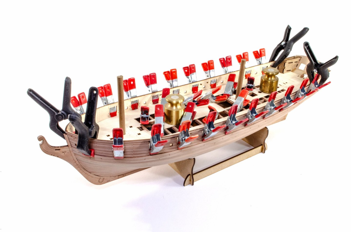
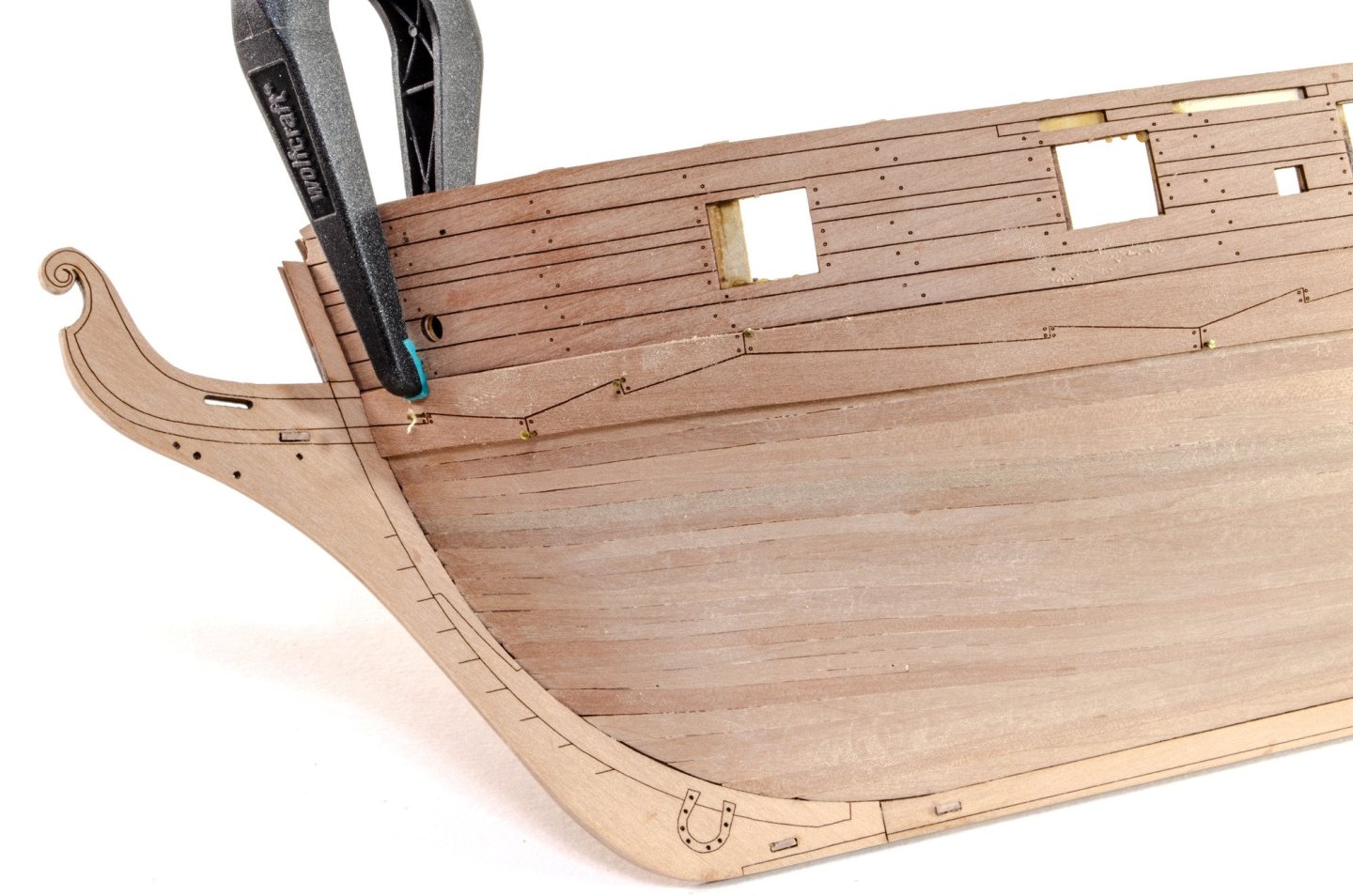
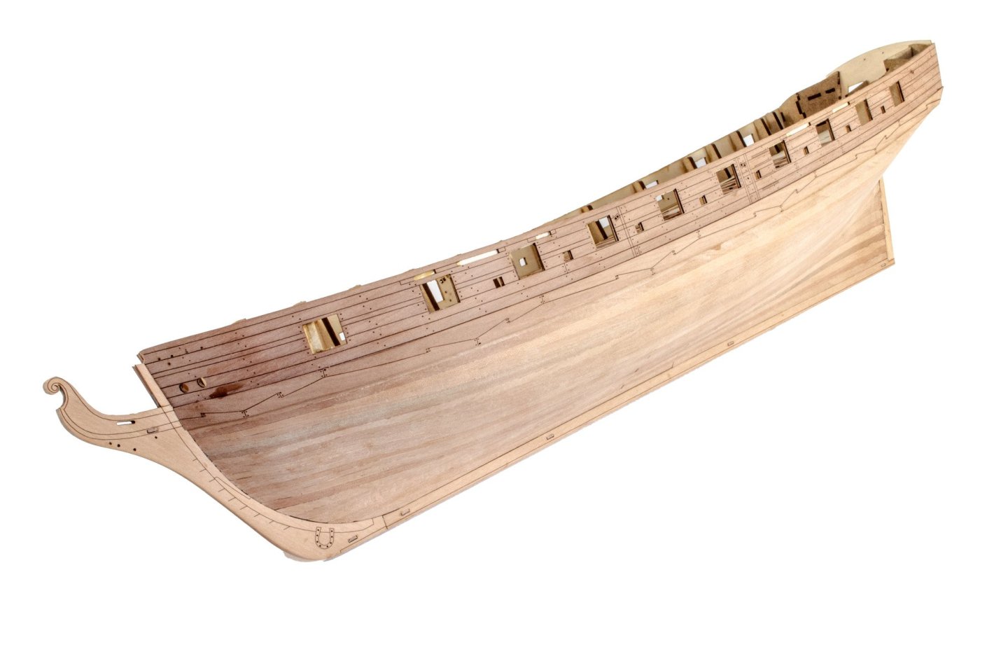
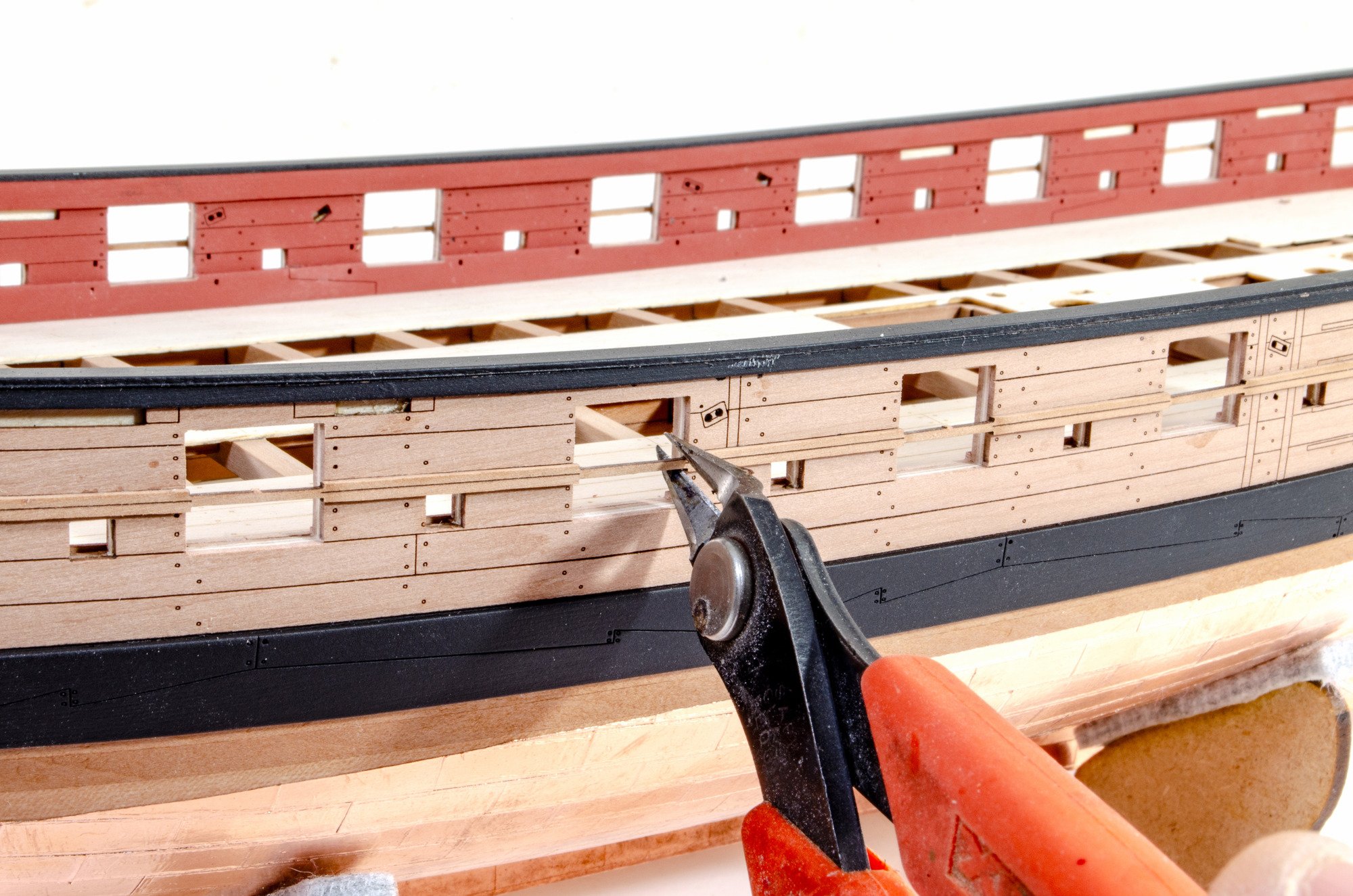
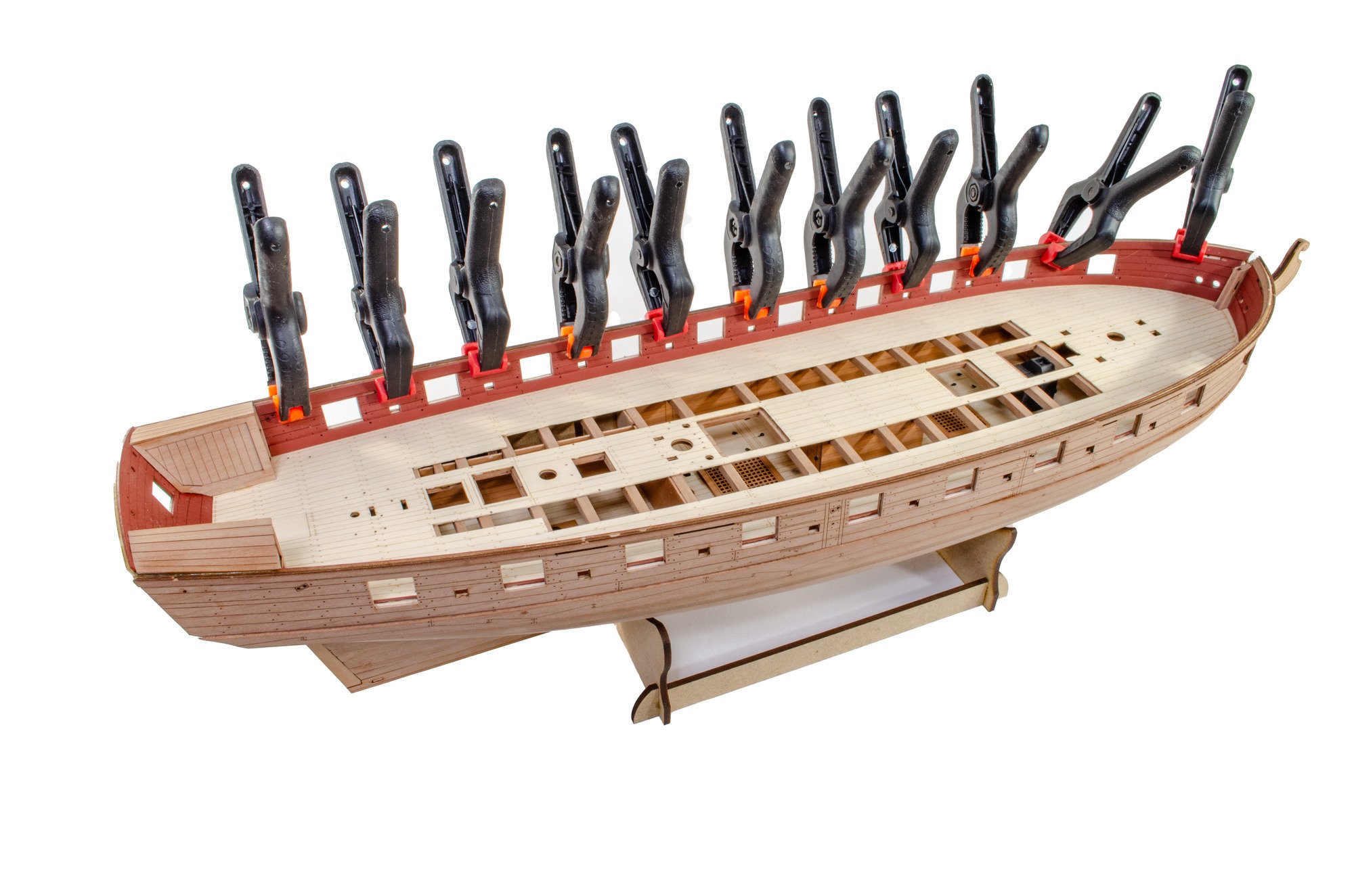
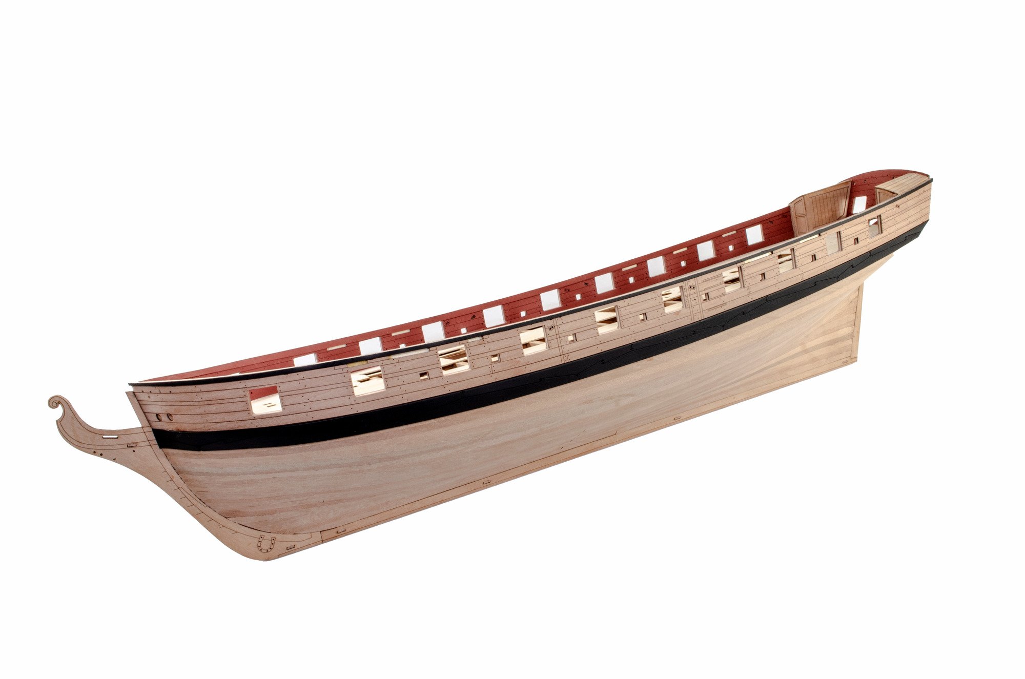
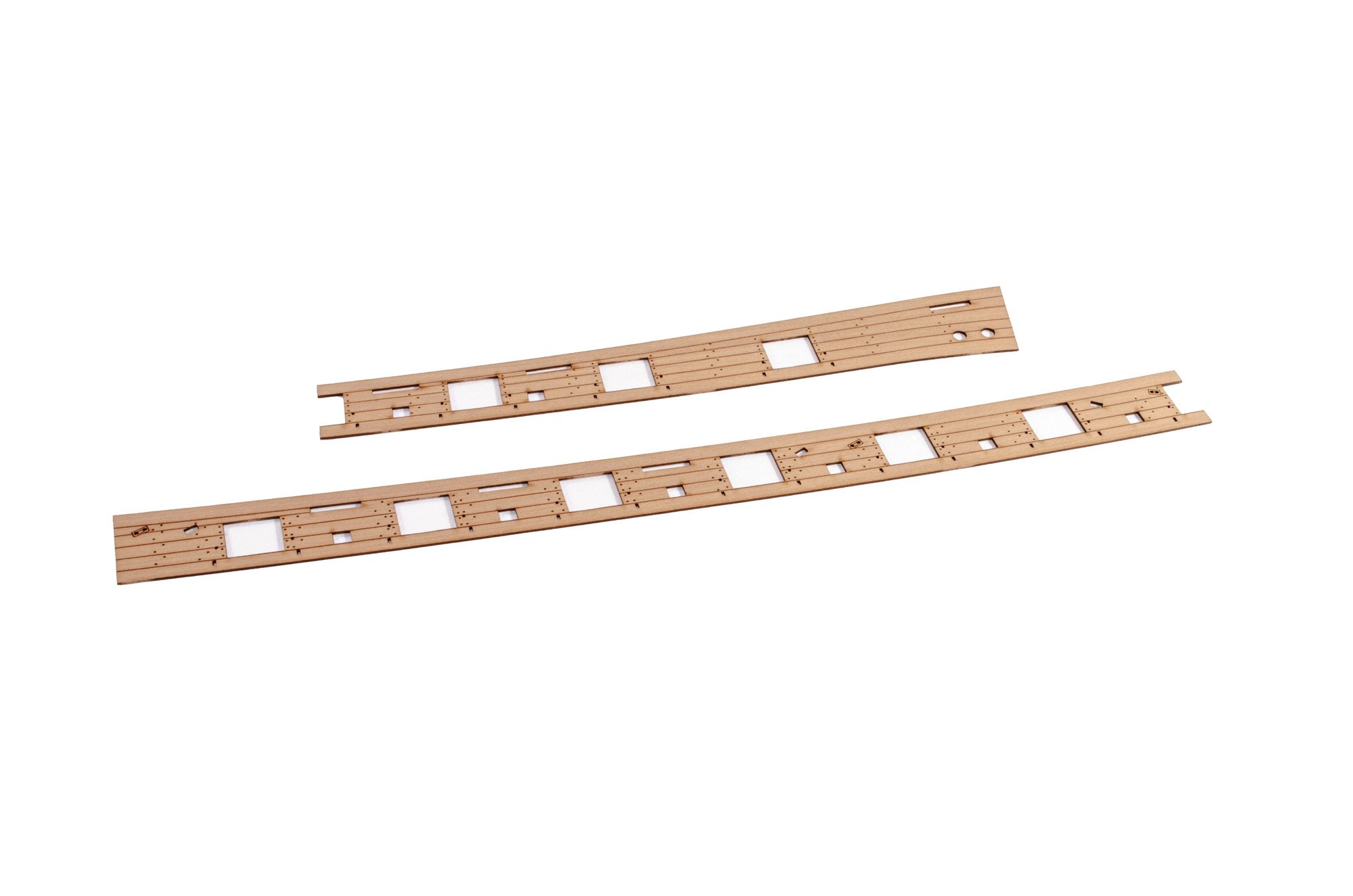
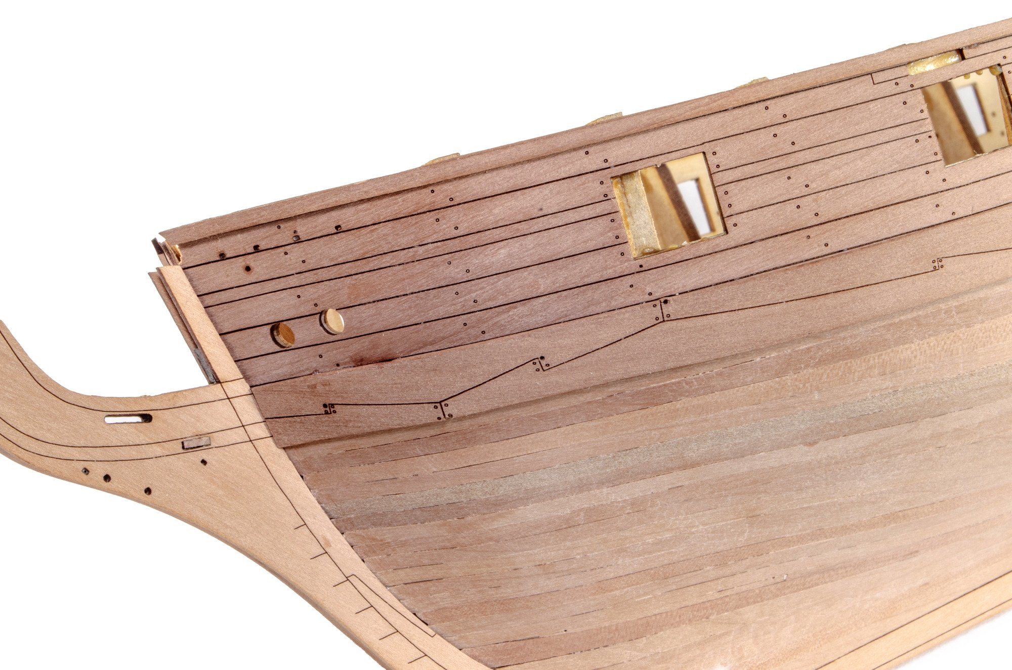
With the first planks done, the outer layer begins with the full length, engraved bulwarks. I did a short soak of the bow area before properly fitting. This was to prevent any possible crack at the top of the fore gunport. I left this to dry for 24hrs so it shrank back to normal size.
When it comes to gluing the bulwarks in place, some MDF port jigs are included, each designed for their specific opening. I used a few of these along the way.
The bulwarks are very easy to fit. In fact, this hull is one of the friendliest when it comes to planking and adding pre-cut parts such a bulwarks and wales. After these were fitted, the hull was planked in pear and then sanded smooth.

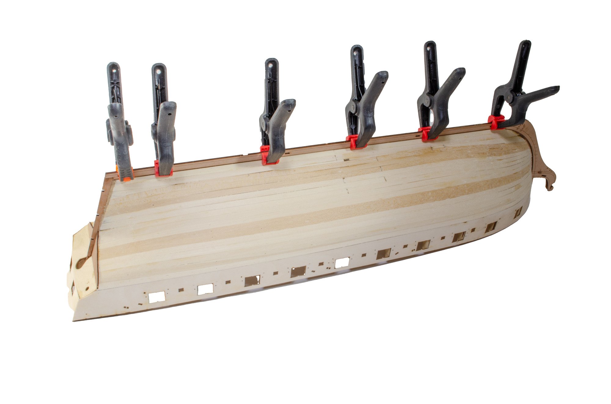
The wales are full length parts, and even with their strange curves when flat, they conform to the hull perfectly. The top of the wale sits along the bottom engraved line on each bulwark. The forward end of the bulwarks were soaked in water for 10 mins before being clamped/pinned to the hull until they dried out.
A rail is now added to the top side of each bulwark. Look closely and you'll see it.

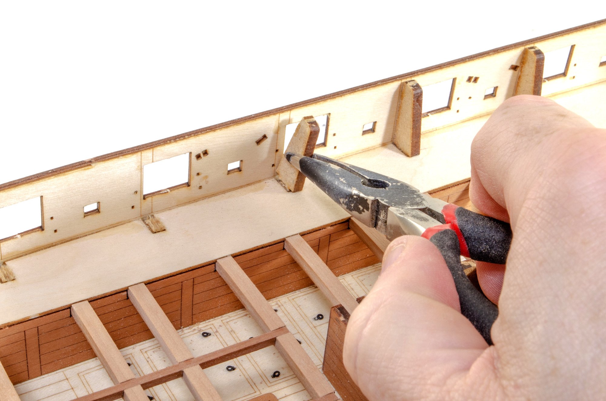
One of my favourite parts and one that signifies a corner being turned; removing the MDF bulwark ears.

More in a few minutes....
-
1 hour ago, Hawaii said:
Aloha from Hawaii. I have this kit but am missing the instructions. Anyone know where/how I can get the instructions?
Have you tried contacting Panart through their website?
-
I can tell you that their next kit will be a 'large' one.
That's it...
- mtaylor, thibaultron, PaddyO and 1 other
-
4
-
In addition, some of these paints I DO use are actually primers anyway. I use Plastikote red oxide primer, and while primer from their spray can range.
- mtaylor, KentM, Ryland Craze and 4 others
-
7
-
Just now, palmerit said:
Question: Before painting wood (whether small pieces or parts of the hull or masts), do you use a primer or sanding seal (to limit the wood fibers from rising up)?
It doesn't do any harm to use a coat of varnish or sanding sealer, as long as it won't react with paint.
For what you see here....no, I don't prime. I prep all parts by sanding them smooth with 320 grit paper and dusting off. That's how I do most of what you see, except for Indy's main paint scheme. I used sanding sealer on that.
-
1 hour ago, palmerit said:
What is the difficulty of this kit?
It’s looking to be a Level 3 ‘Experienced’ but that is mostly due to rig. The hull itself would be a level lower, but we have to factor in the rig.
- Oboship, Ryland Craze, KentM and 6 others
-
9
-
Don't apply glue to the bulkhead ears. It will be a nightmare to remove those ears later and will make an unholy mess...as well as pull chunks from the bulwarks.
Only apply glue along the deck height (lowest deck line) and to where the lower bulkheads are. Alternatively, you can dry clamp everything and then brush the glue in carefully and sparingly along deck height (keeping away from the bulkhead ears) and also from underneath into where the bulwark and bulkheads meet.
-
38 minutes ago, AJohnson said:
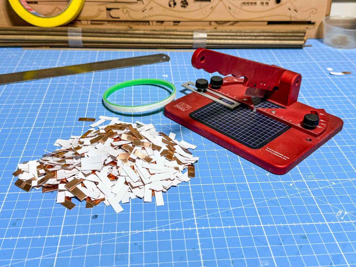
That cutter/guillotine looks good and solid, is it metal? I have cheap plastic one that rocks about when cutting strip, so don’t use it much.
All metal. Check out the review here:
- thibaultron, AJohnson, chris watton and 3 others
-
4
-
 2
2
-
Continued.
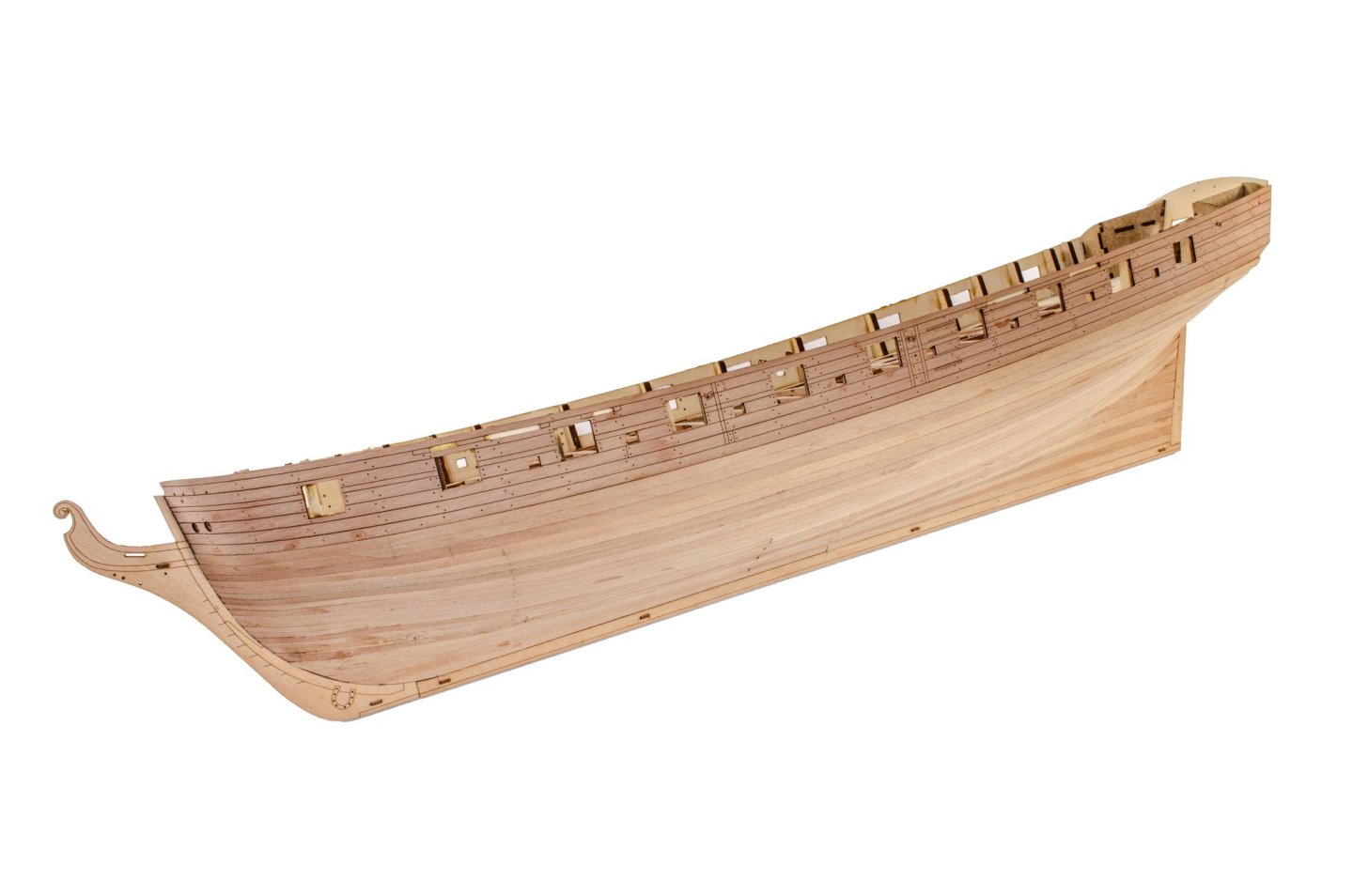
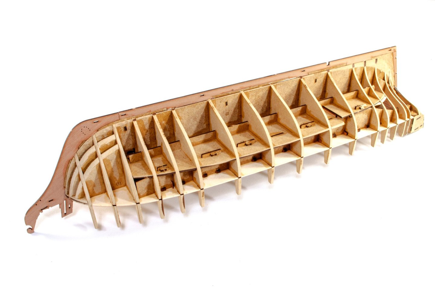
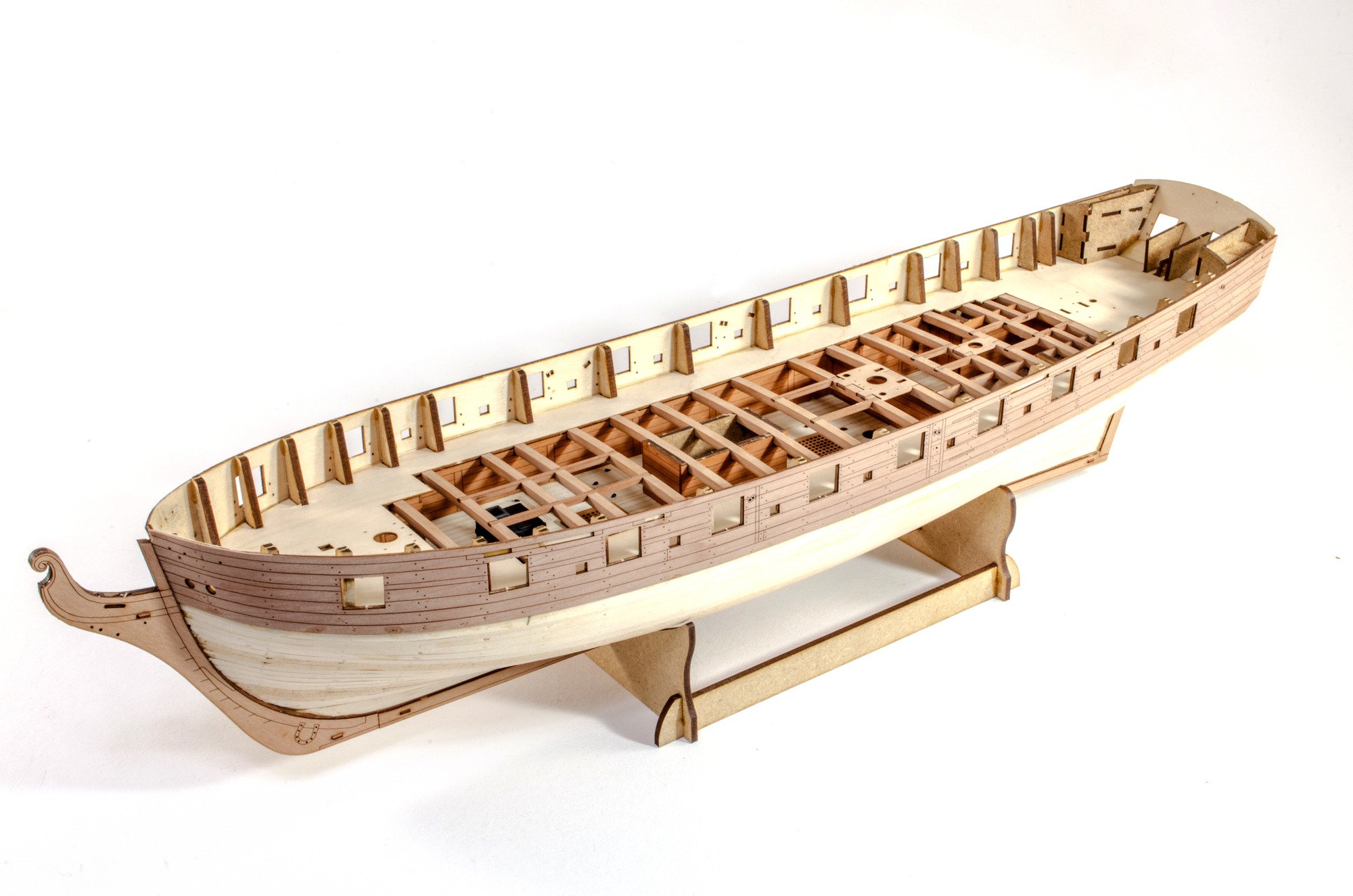
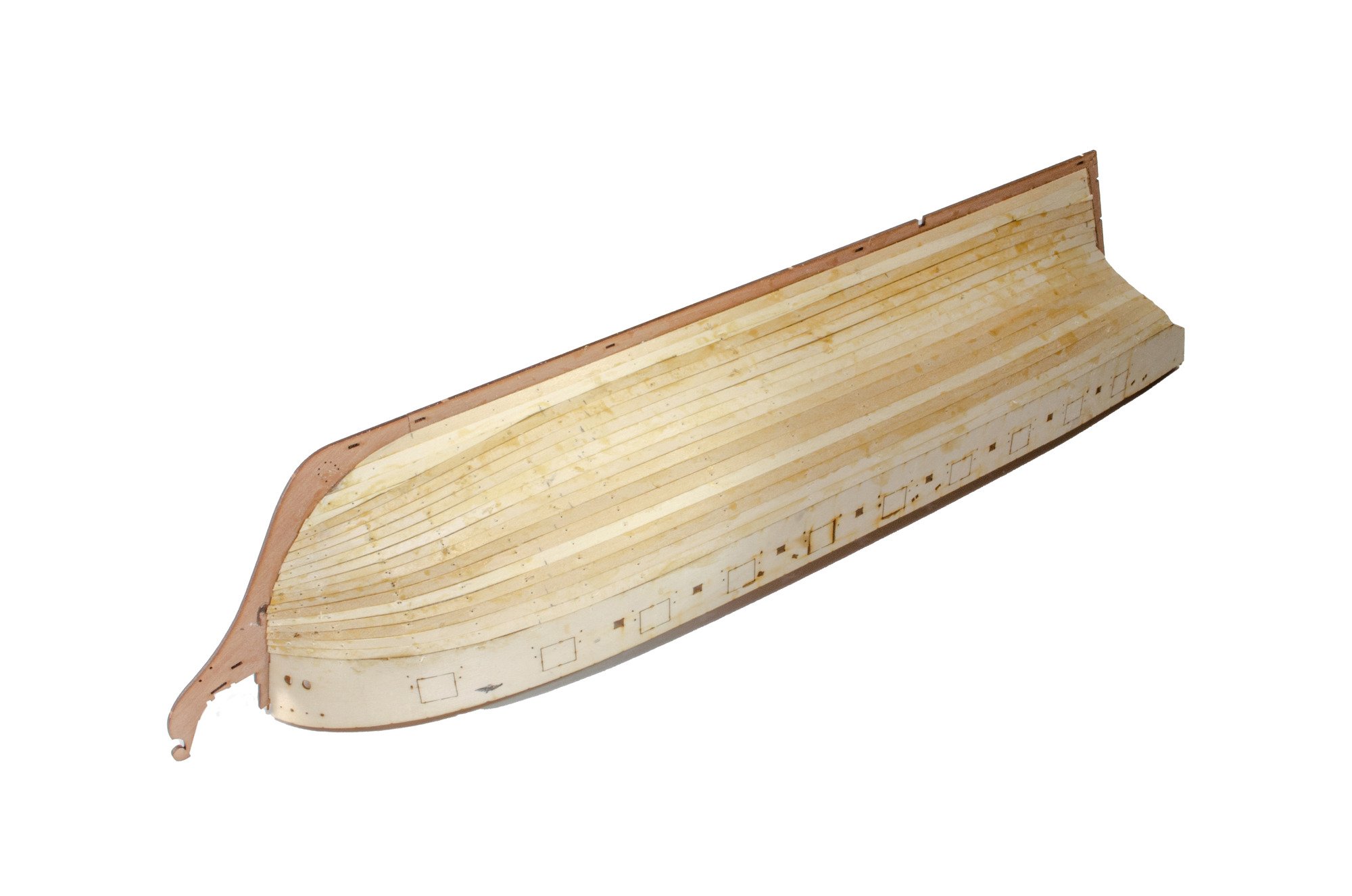
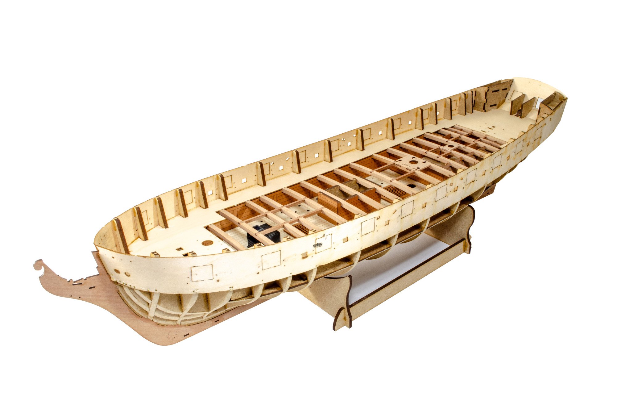
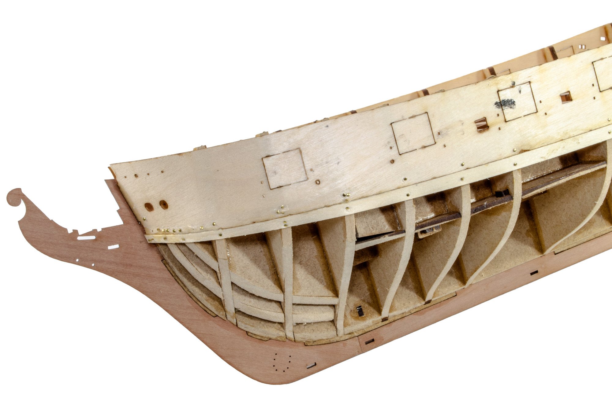
The hull is now fully planked, and using my usual protective tape on the inner keel areas, the whole lot was sanded smooth. I show a block, but most of the work was done with a sanding mouse, now that I feel confident enough to use it without making gaping holes.


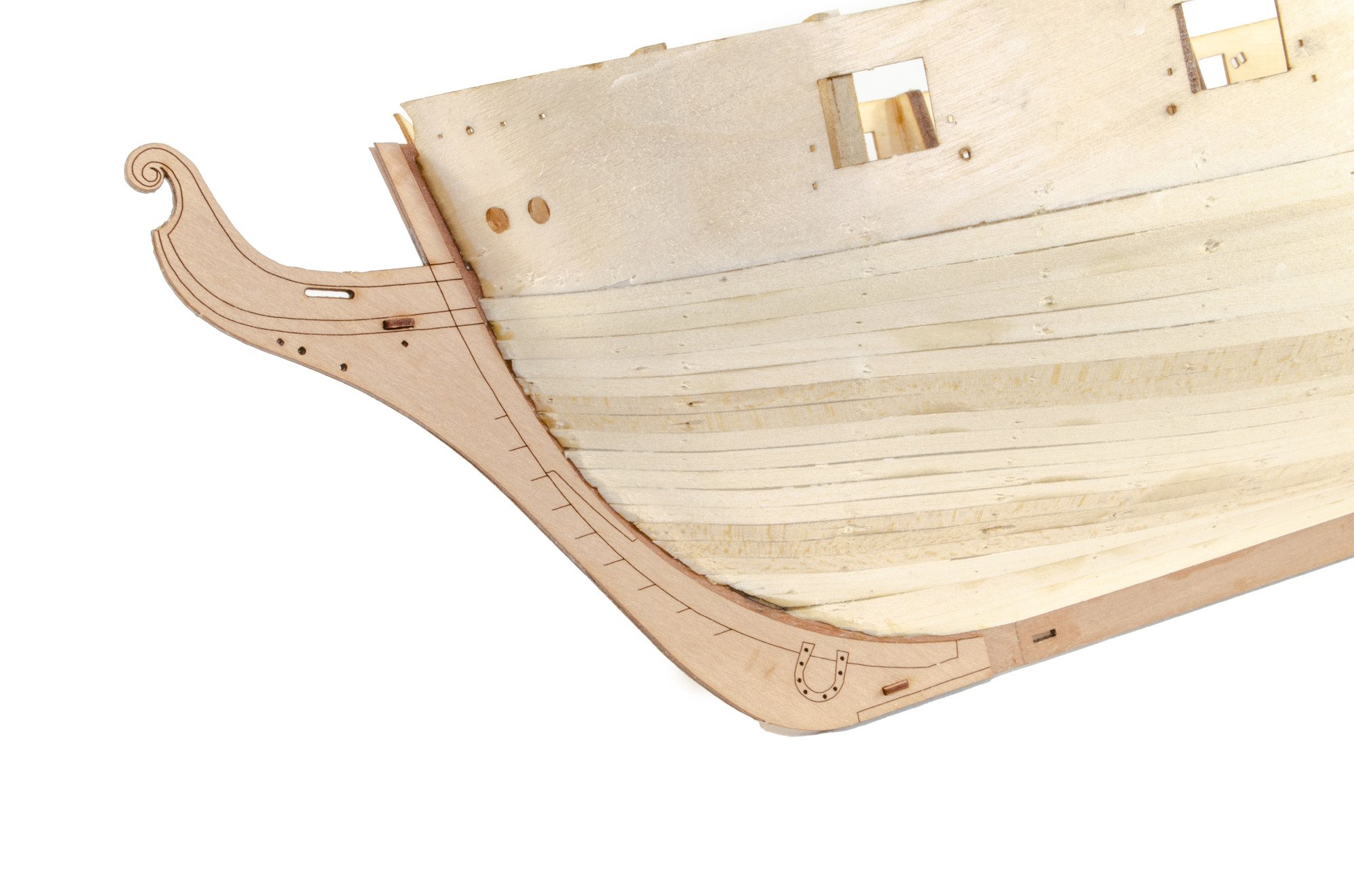
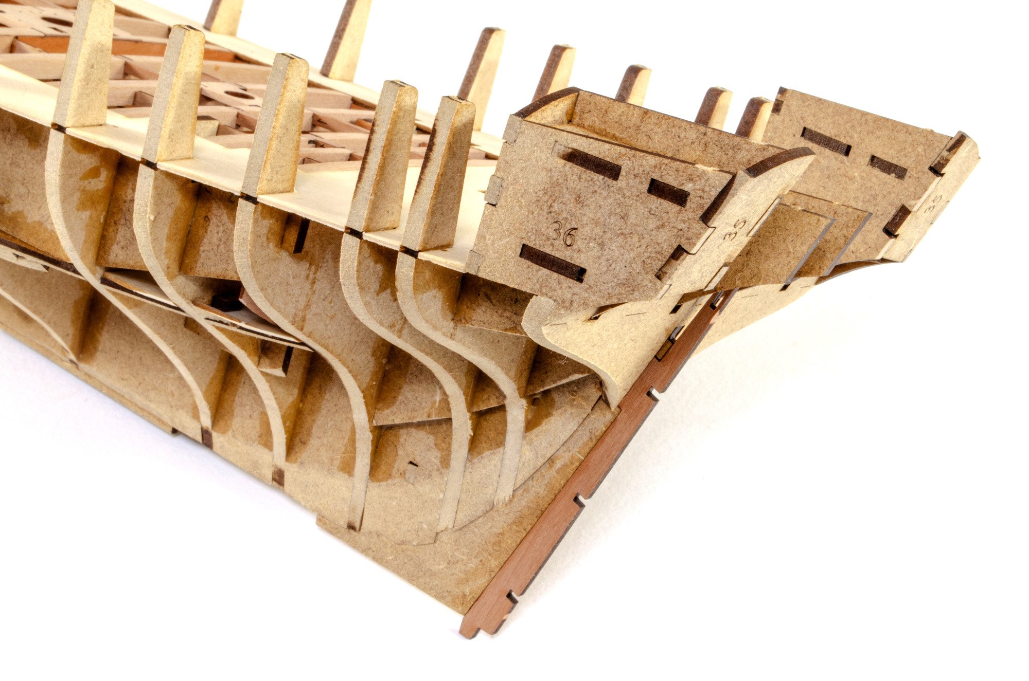
The lower stern planking sections are added. These are made up from two engraved parts.
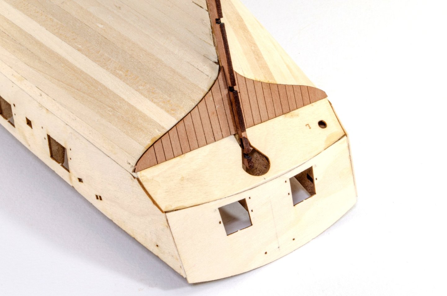
Pear prow, keel and rudder post are fitted and wooden alignment pegs used to get the job right.


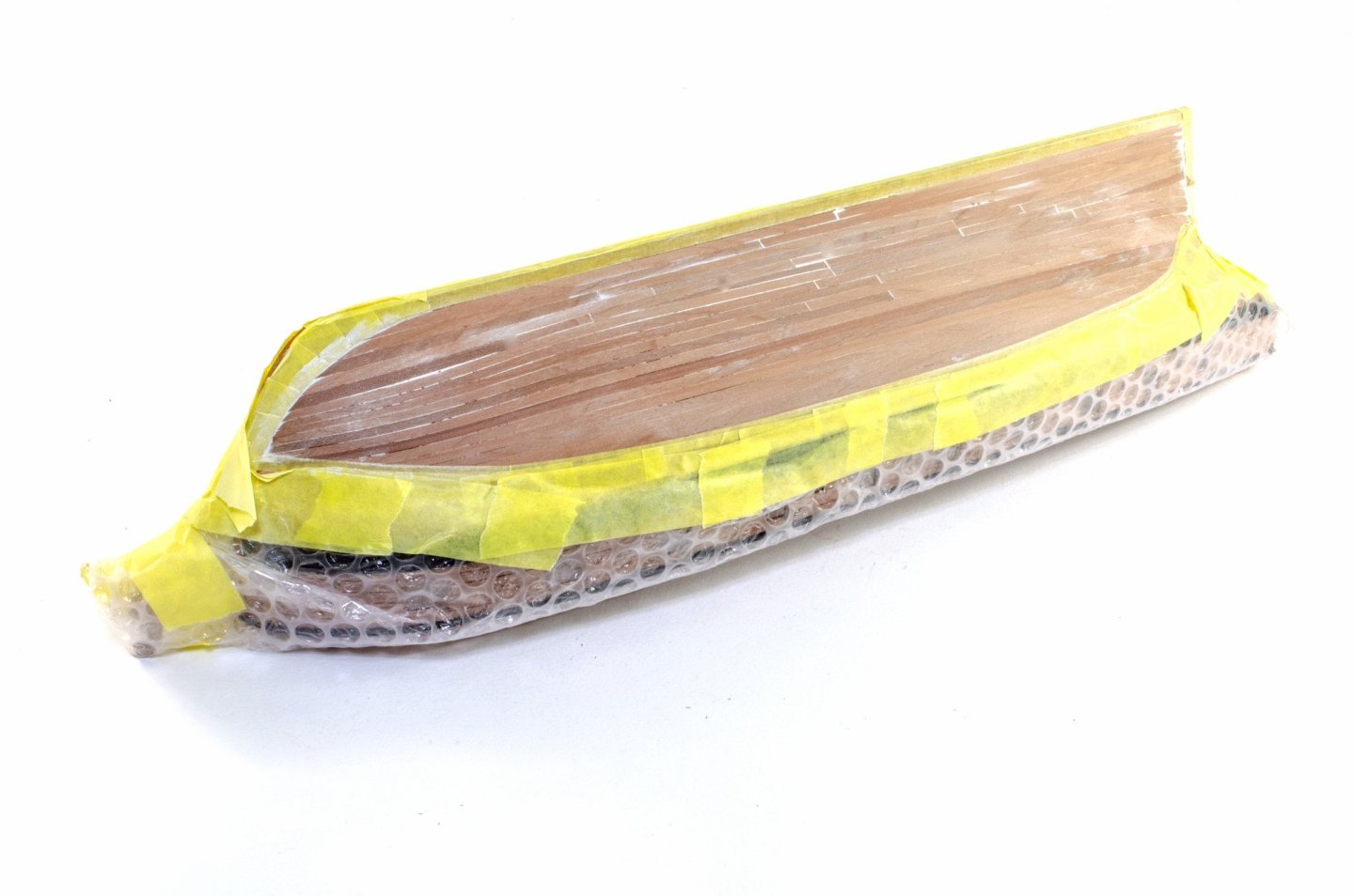
At the moment, I'm waiting for the outer bulwarks to shrink back after soaking. I thought I'd do something useful and got this pile of copper tile made from the roll of self-adhesive copper tape supplied in the kit.
Me done for today!
-
Update time, and possibly my last before I go on holiday.
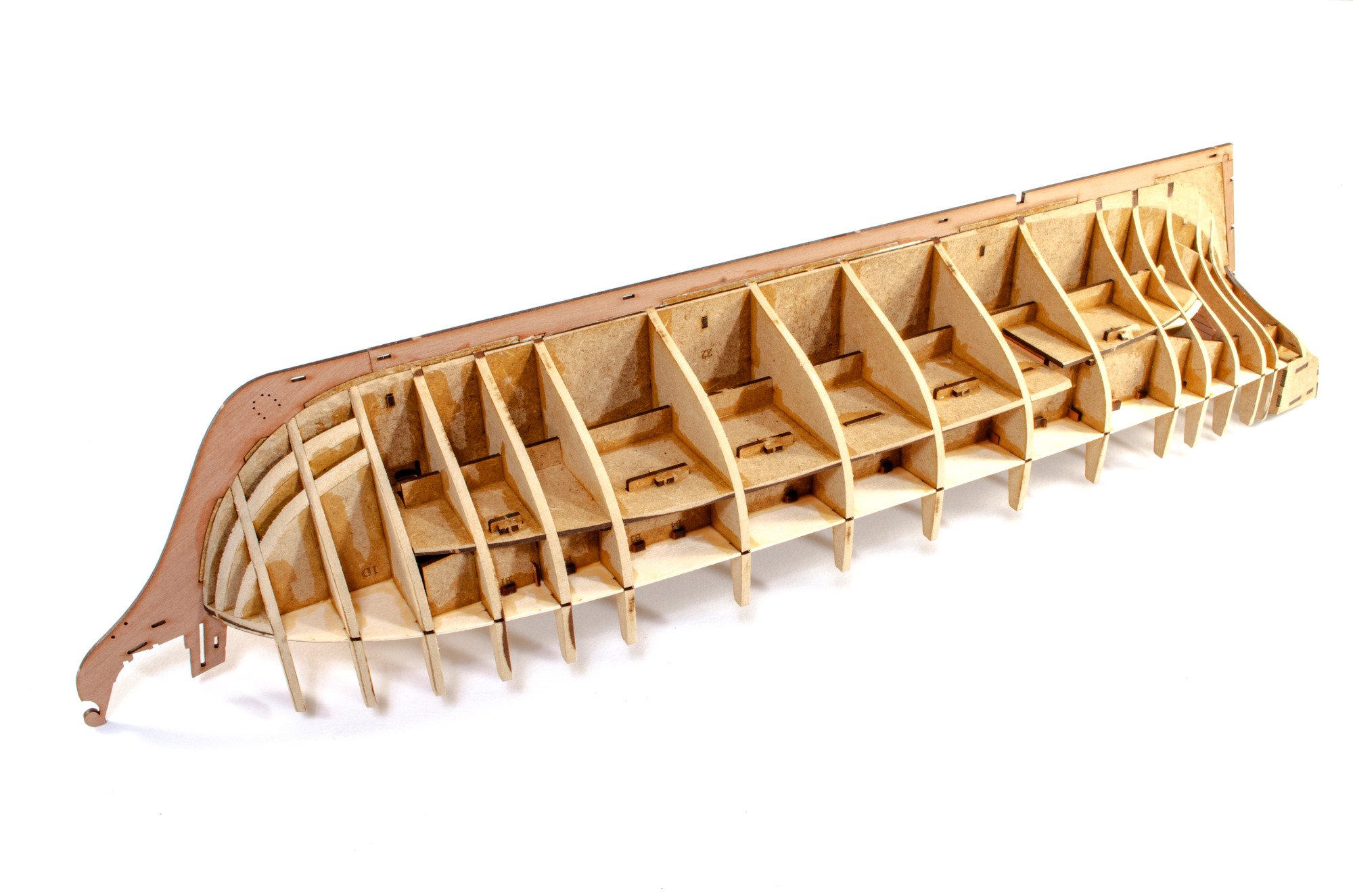
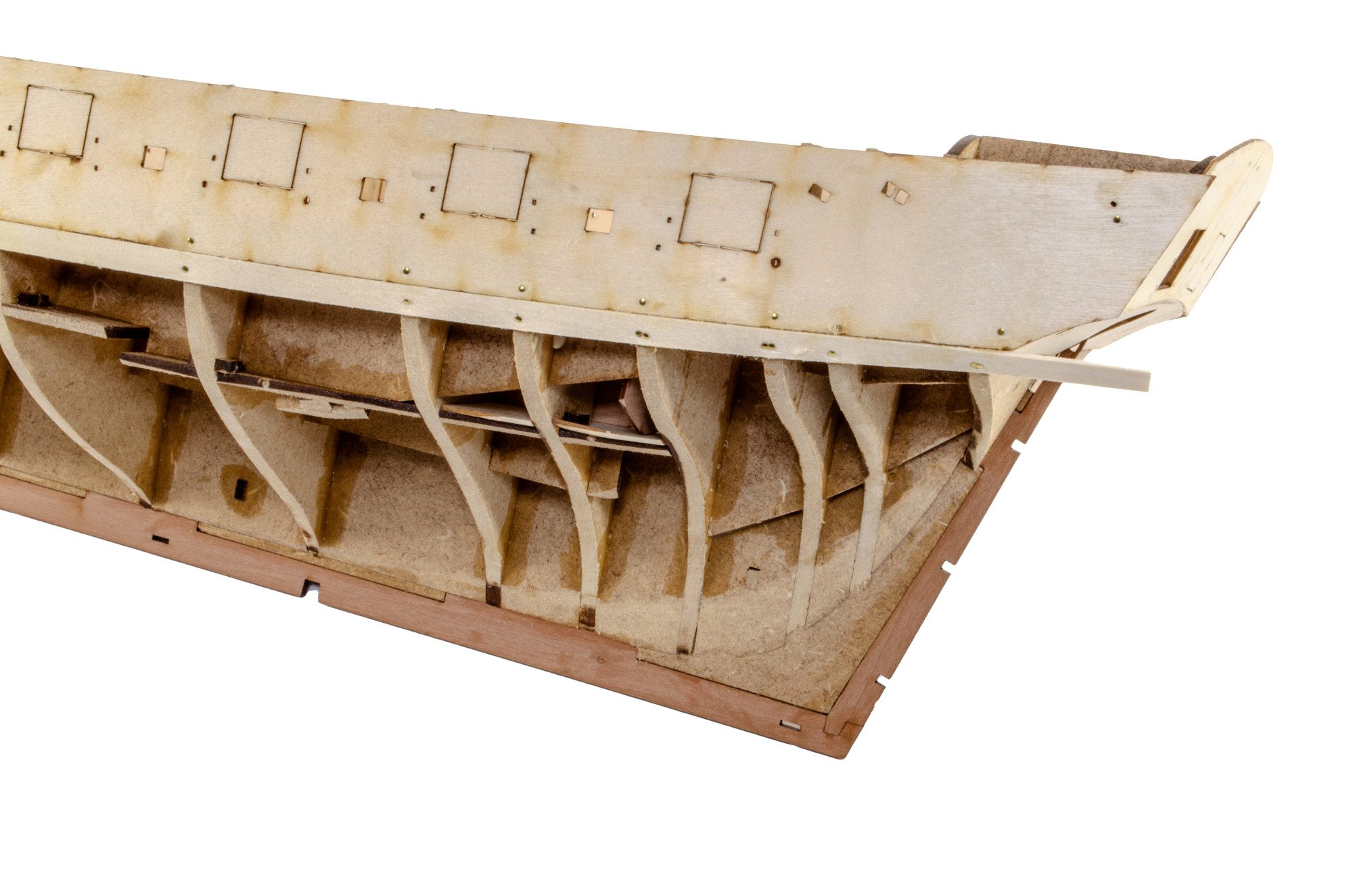
As the weather here had got better, I could finally get the hull faired. With that task done, I went about fitting the inner pear prow, keel and rudder post.
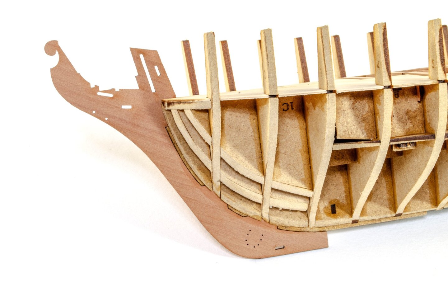

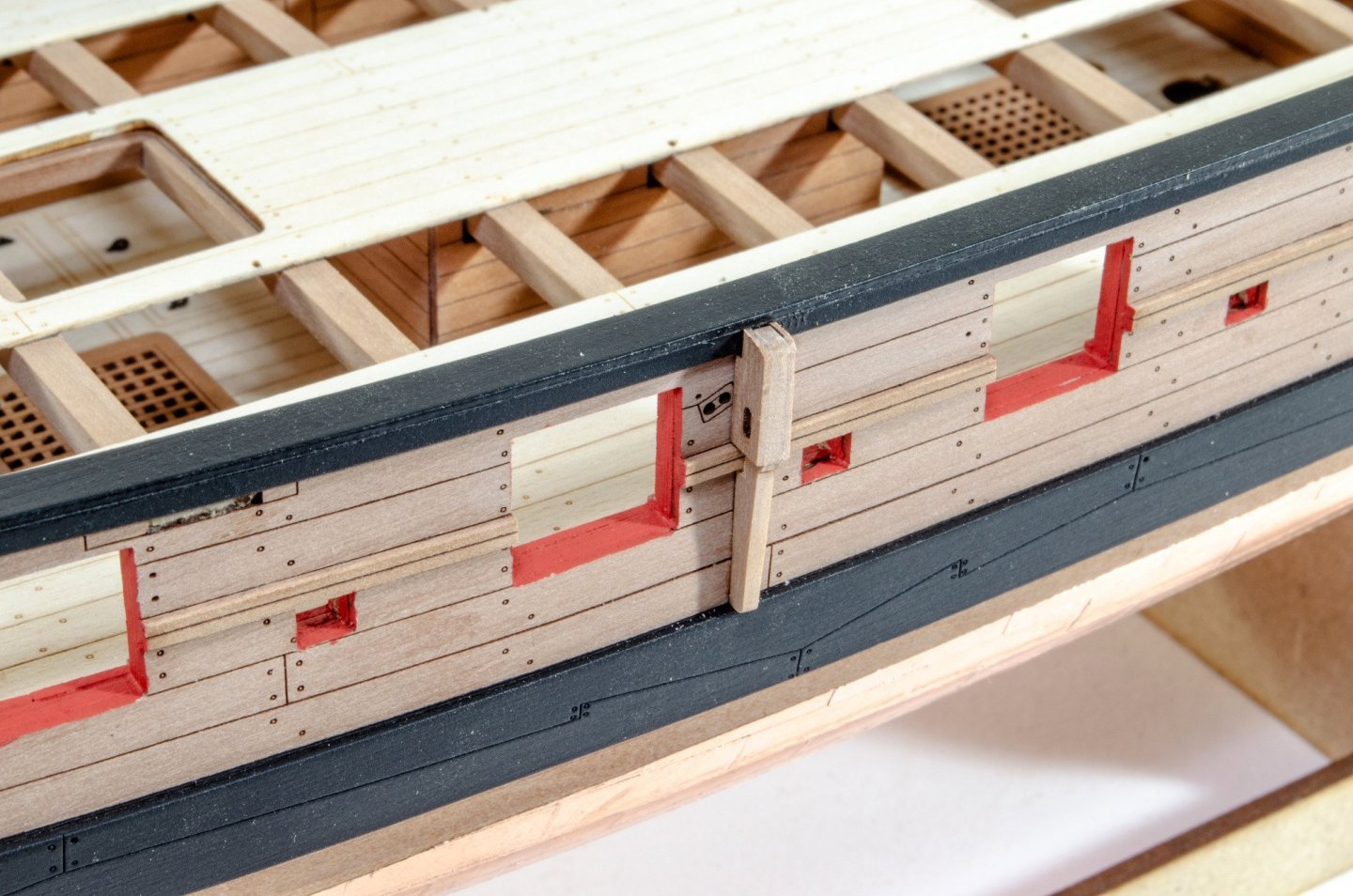
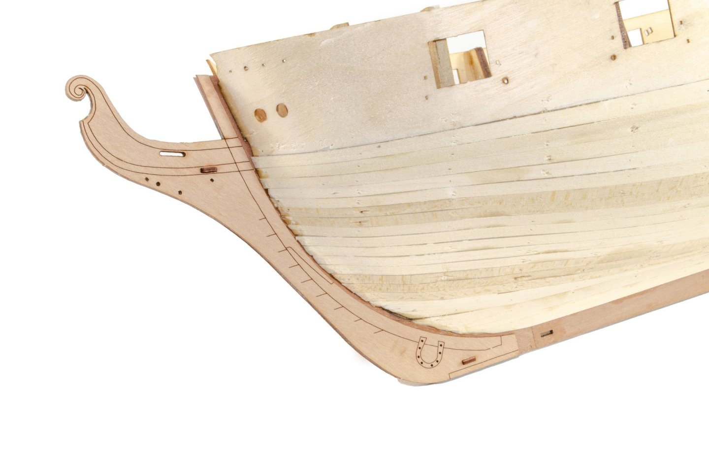
I desperately wanted to get onto the stern, to give it more rigidity in that area. These two 0.8mm ply parts were then fitted. I drew some pencil lines to help with fitting these centrally. To curve the lower counter, and save time, I added a series of score lines on the reverse.
Any overhang on these parts was now sanded flush with the sides of the hull.
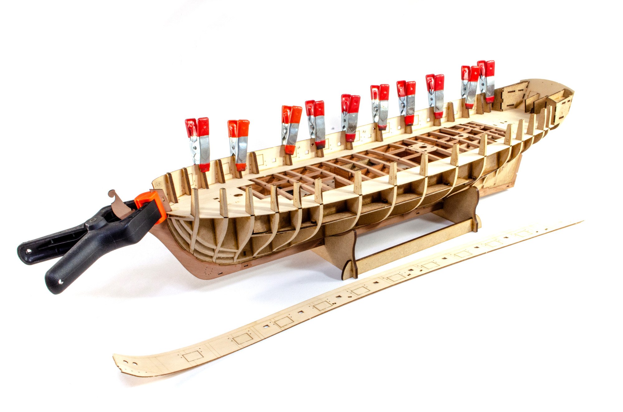
To avoid any kinks in the forward area of the ply bulwark (where the gun ports lay), I soaked the parts and then used an iron and curved block to shape them. These were then fitted/pinned dry. When happy with the positions, they had glue brushed into the joint areas.


Planking is done in my usual cack-handed way. With this hull, the lines are very easy to plank and hardly any stealers needed to used. A first for me±


-
-
Last one for today.
Bitts
These need no explanation. They'll also be painted red before fitting to the hull.


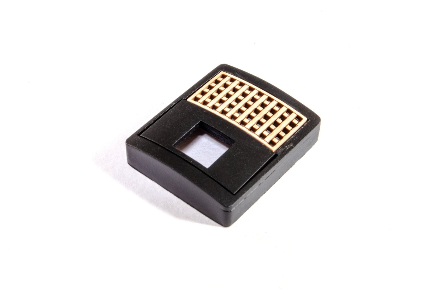
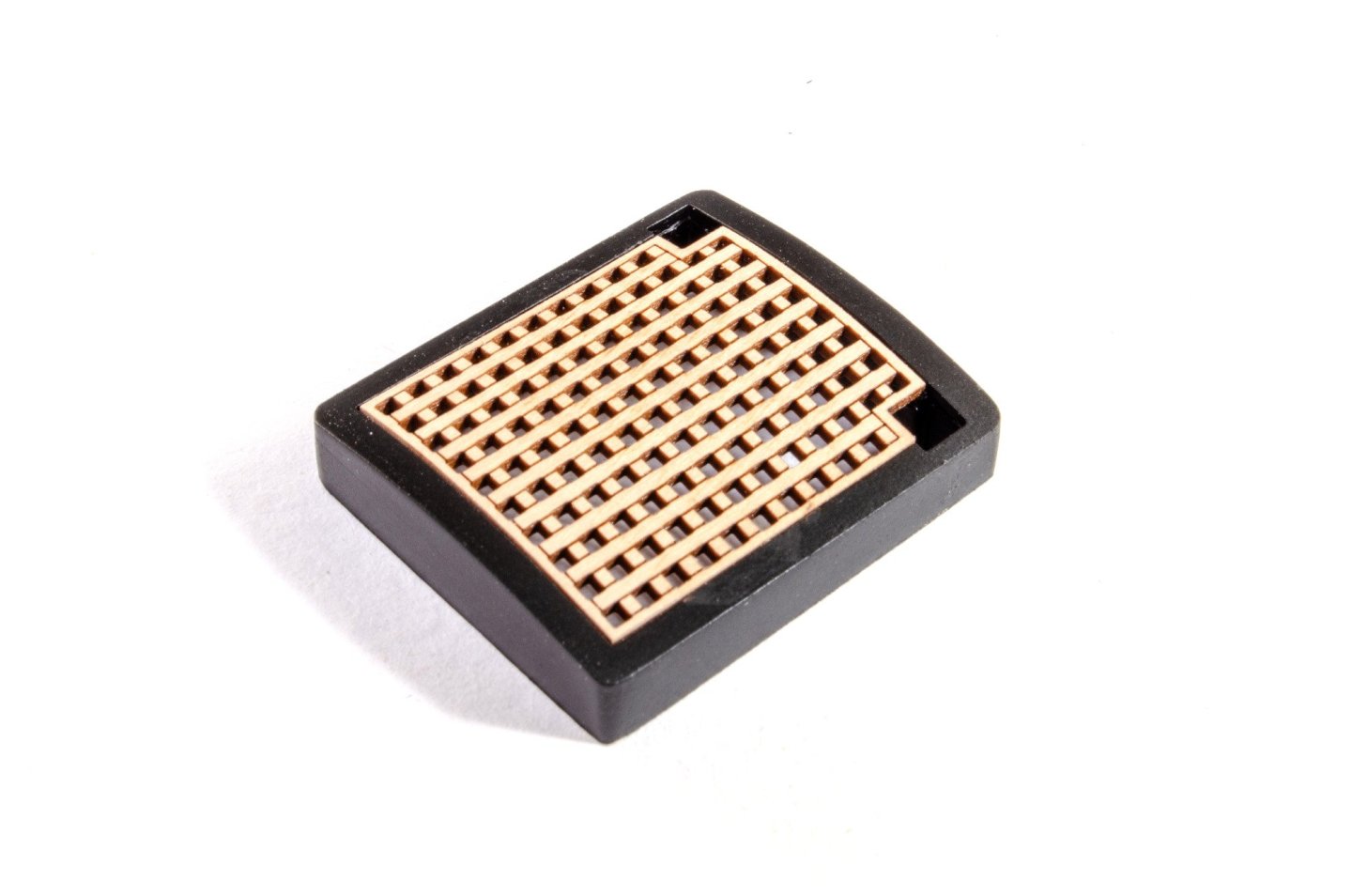
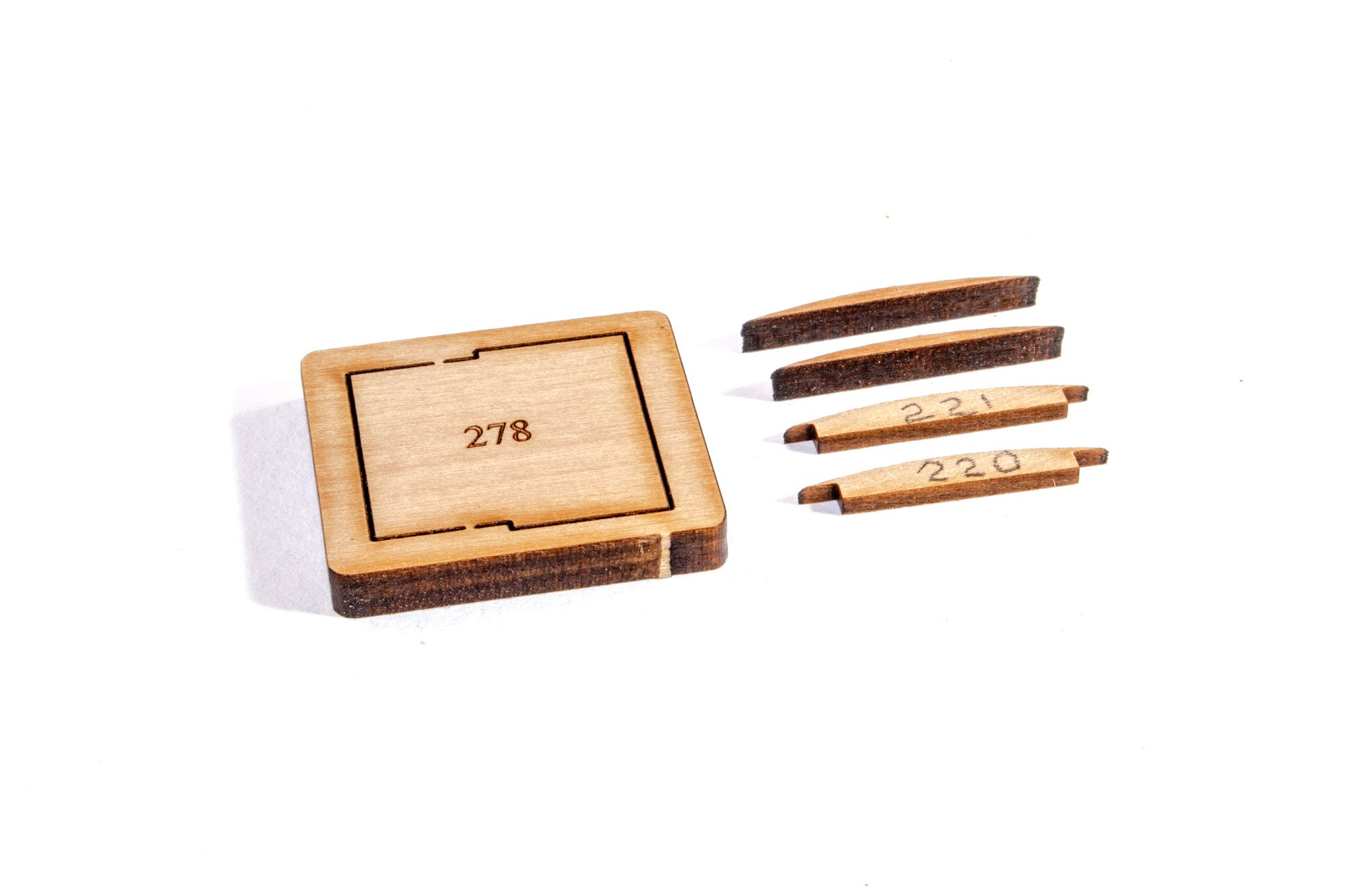
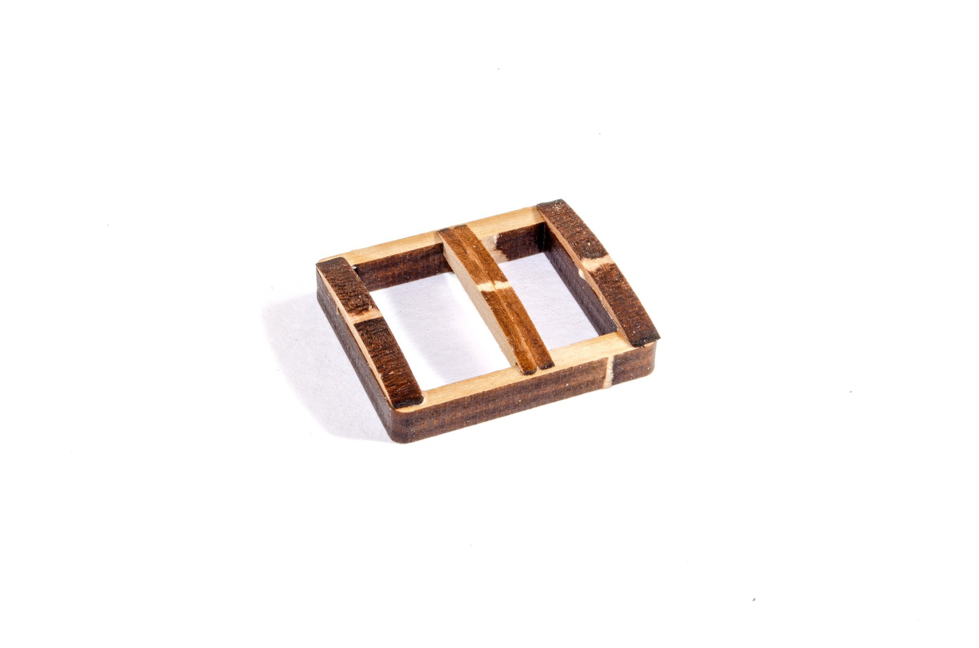
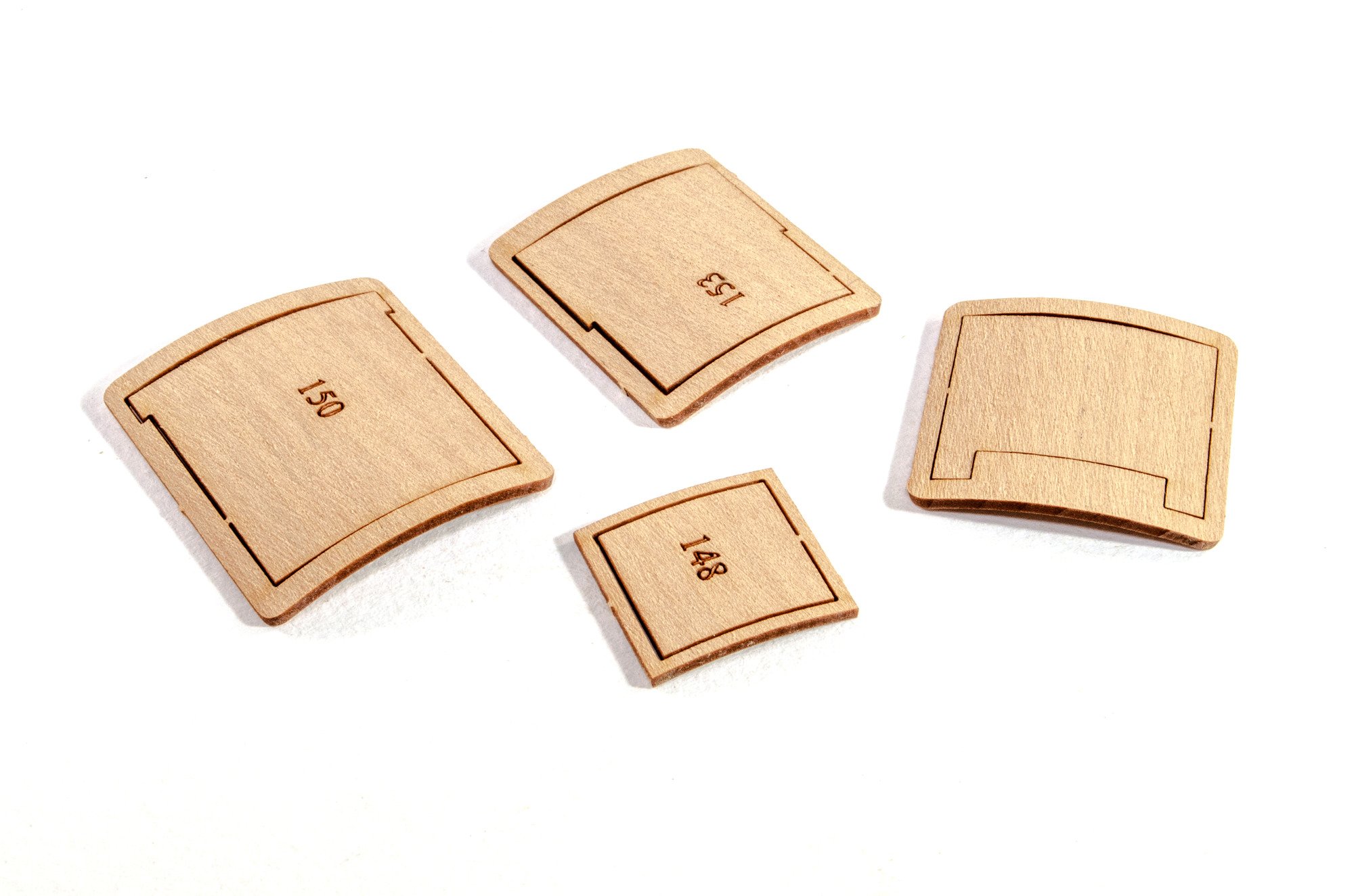
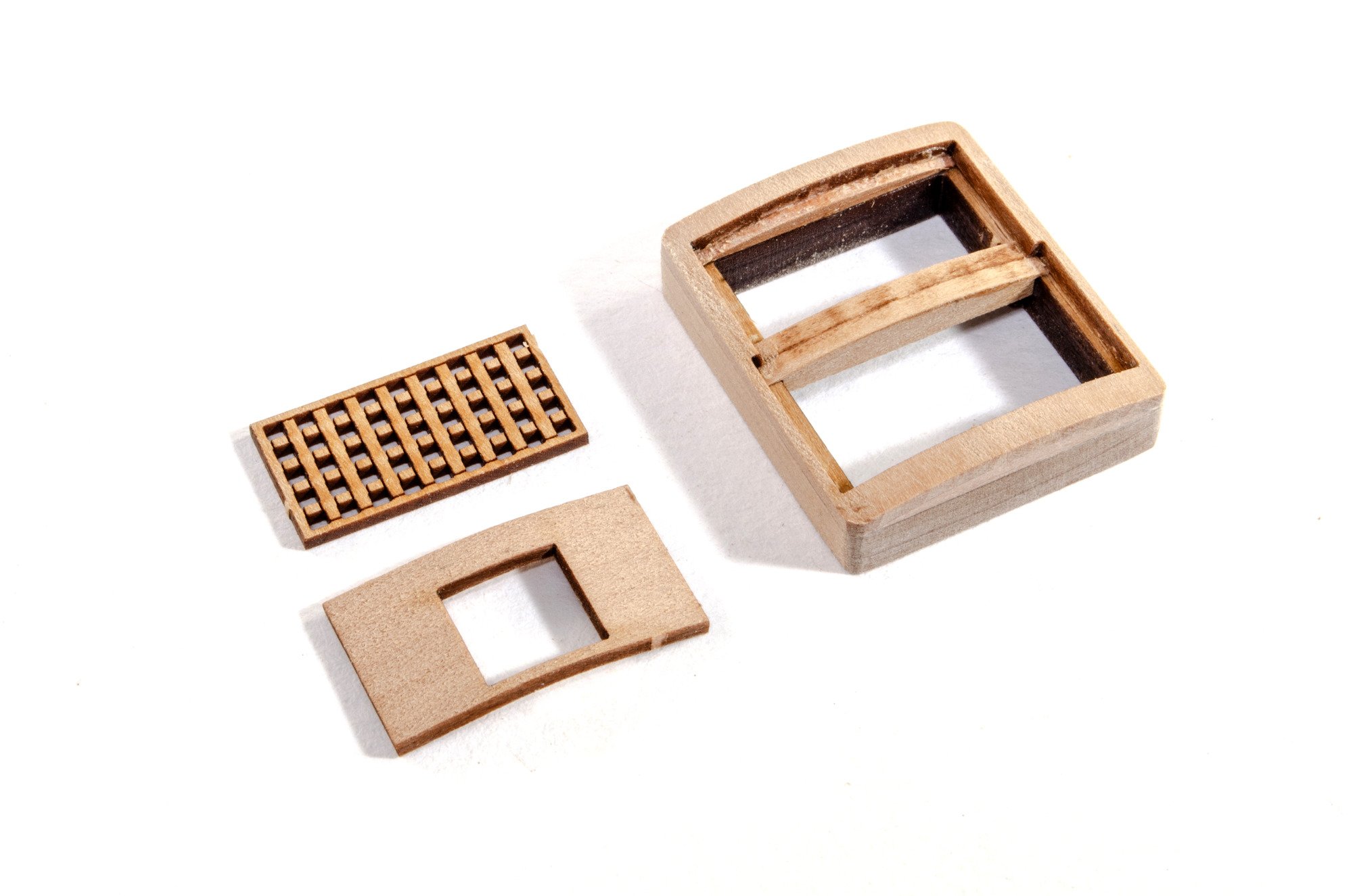
Grates
I'm only showing one unit being built here as they all follow the same pattern, including the coaming that accepts the ladder to access the lower deck. These coamings have curved tops, and are identical in shape to those on the shipyard plans. First, we have to glue the curved top parts into place on the body.

I now soak all the tops and wrap around a tin until thoroughly dry. The centres are also temporarily left in place to add strength and make it easier to neatly and evenly sand the tops of the assemblies.

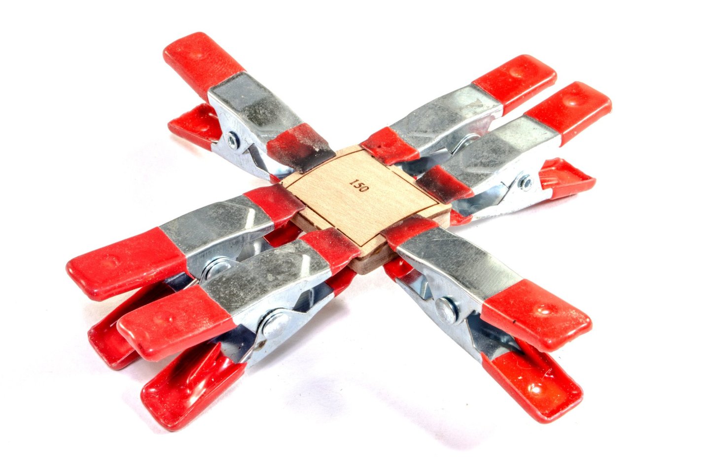
After sanding the units so they are smooth, the coamings can be painted black. Note that this unit has another curved part. This is where the stove chimney will protrude.


Until next time...
-
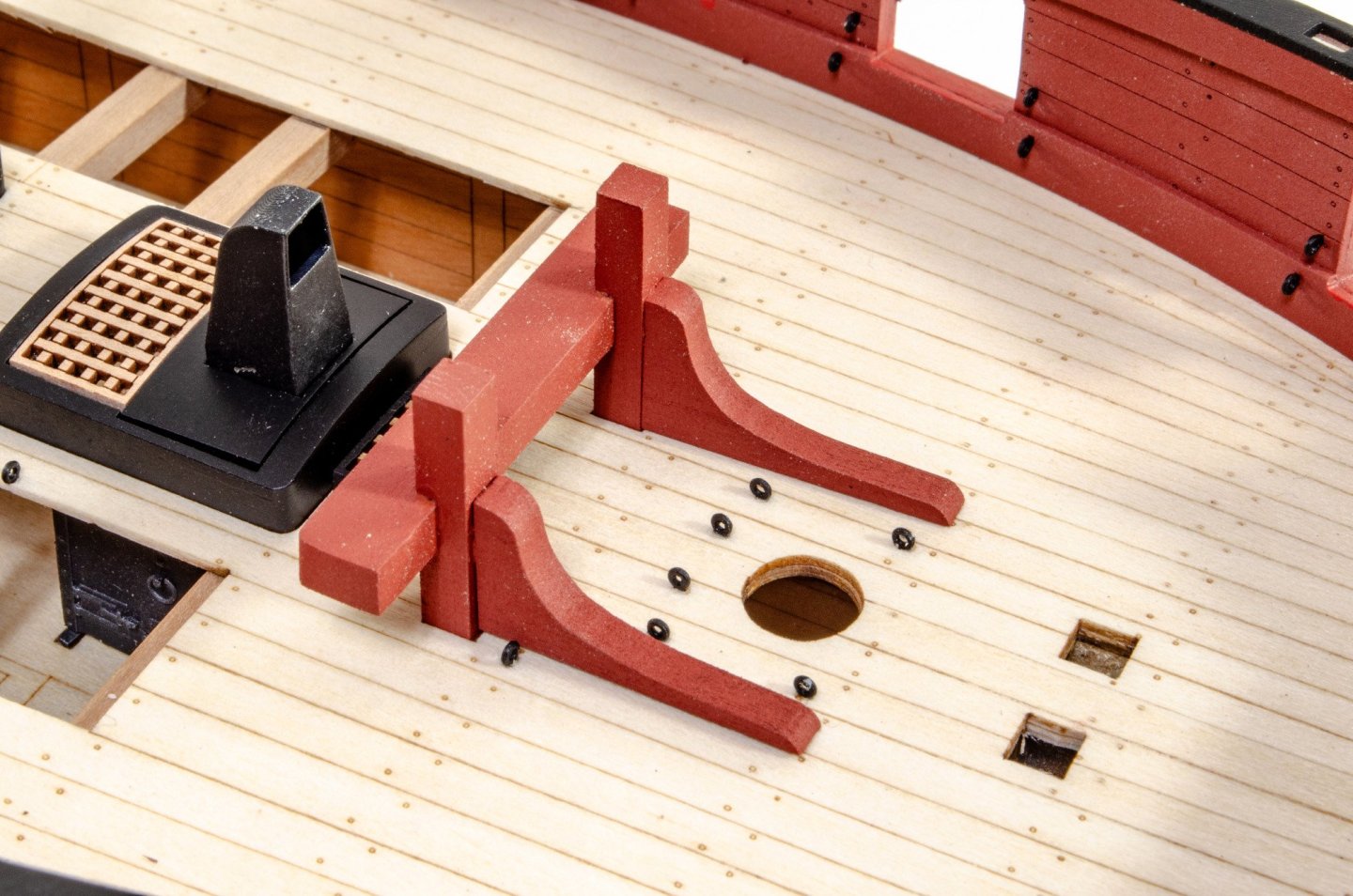
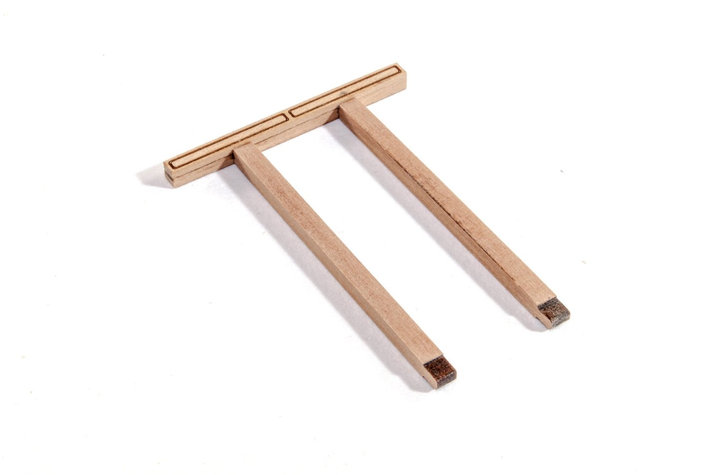
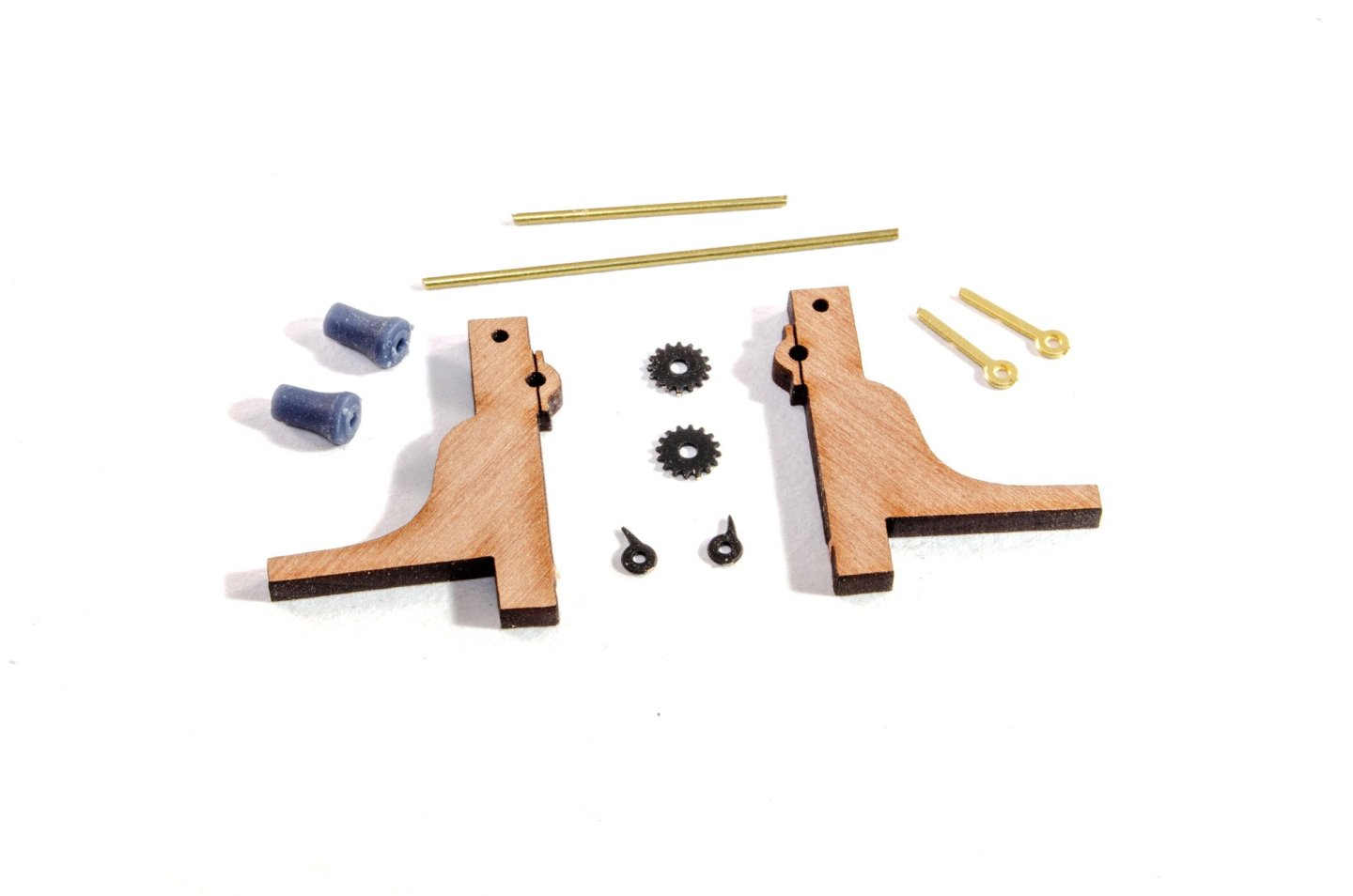
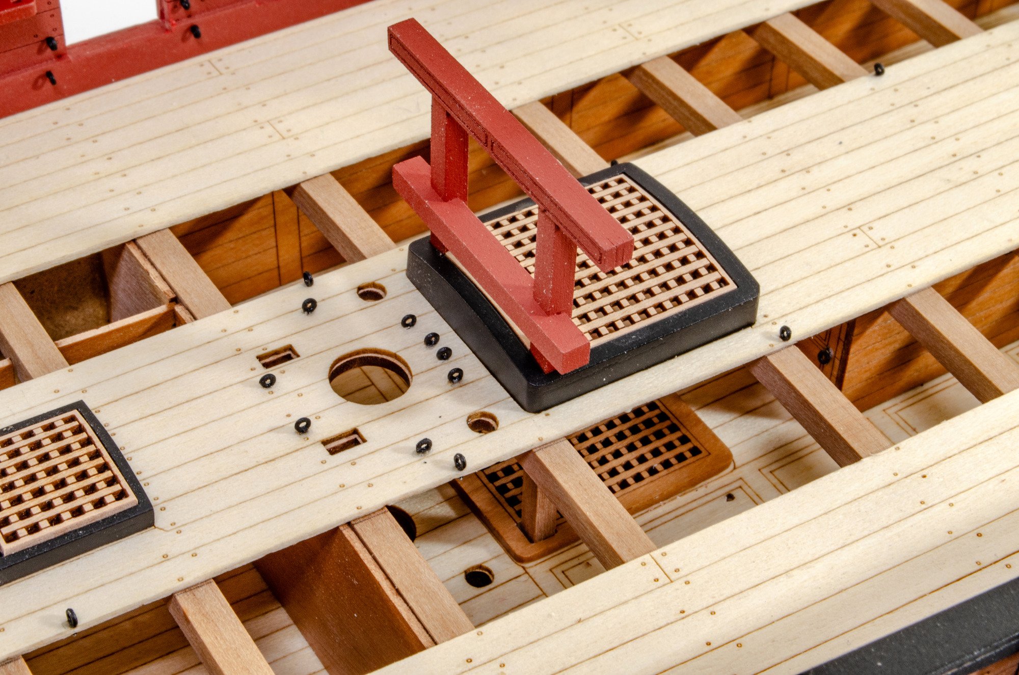
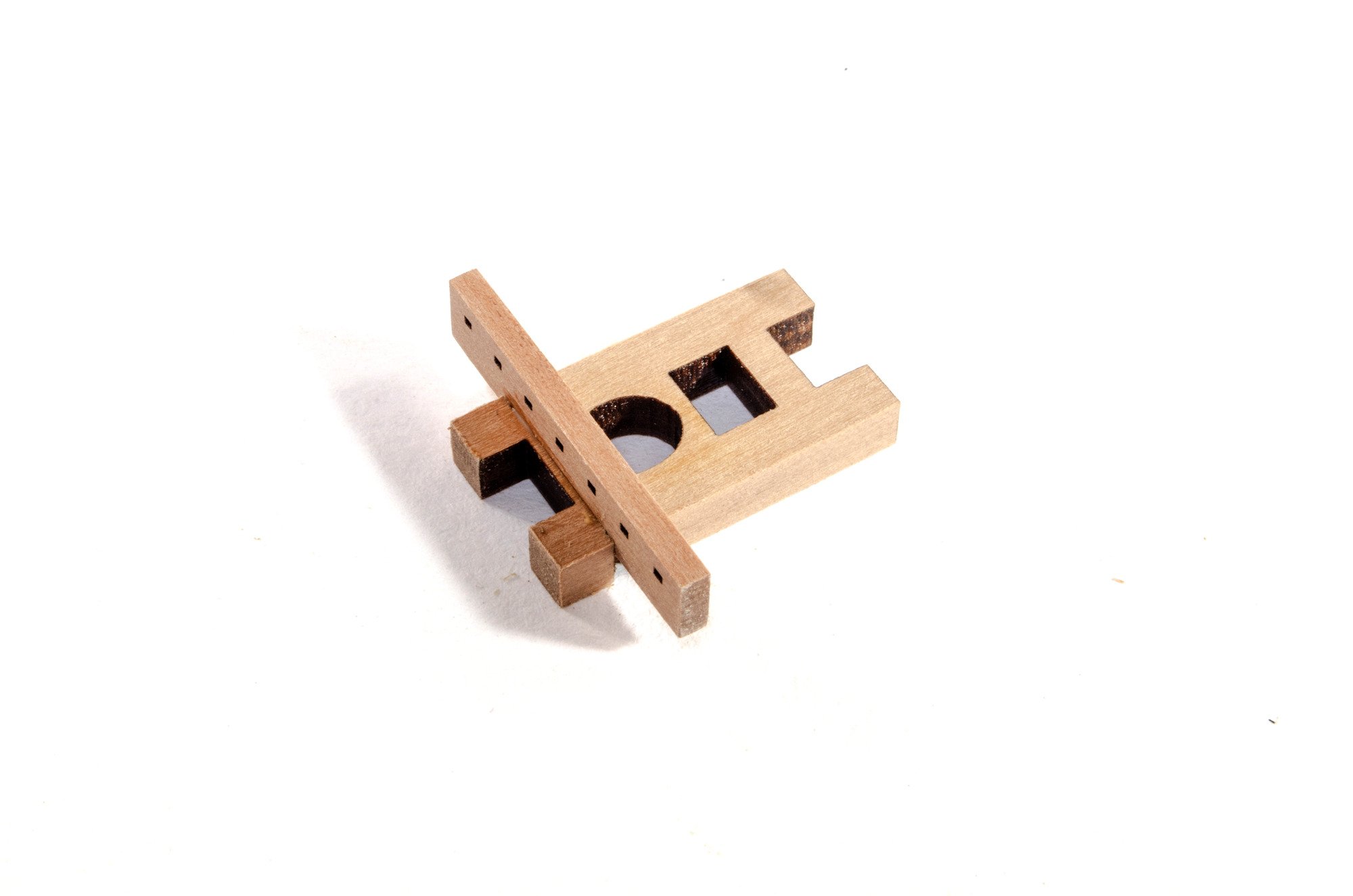
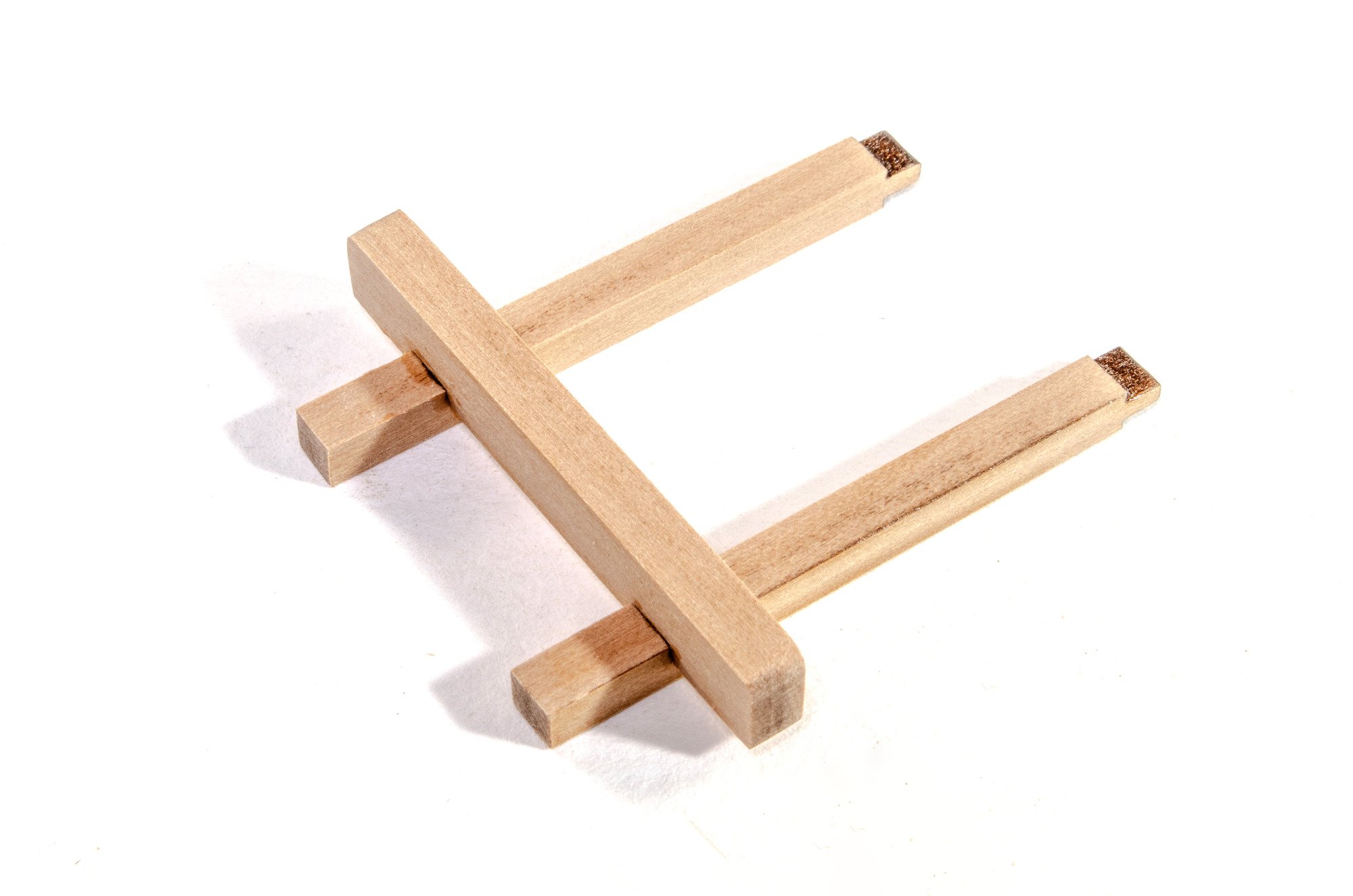
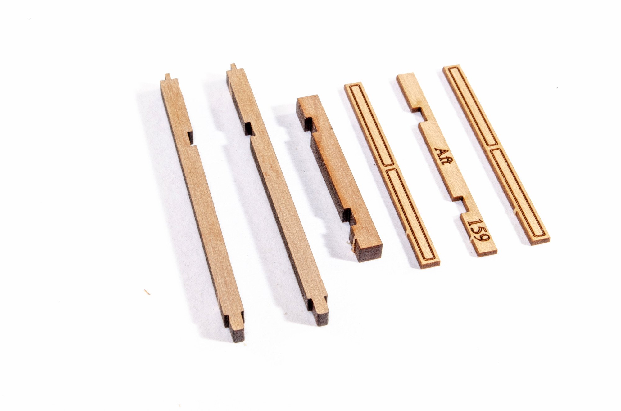
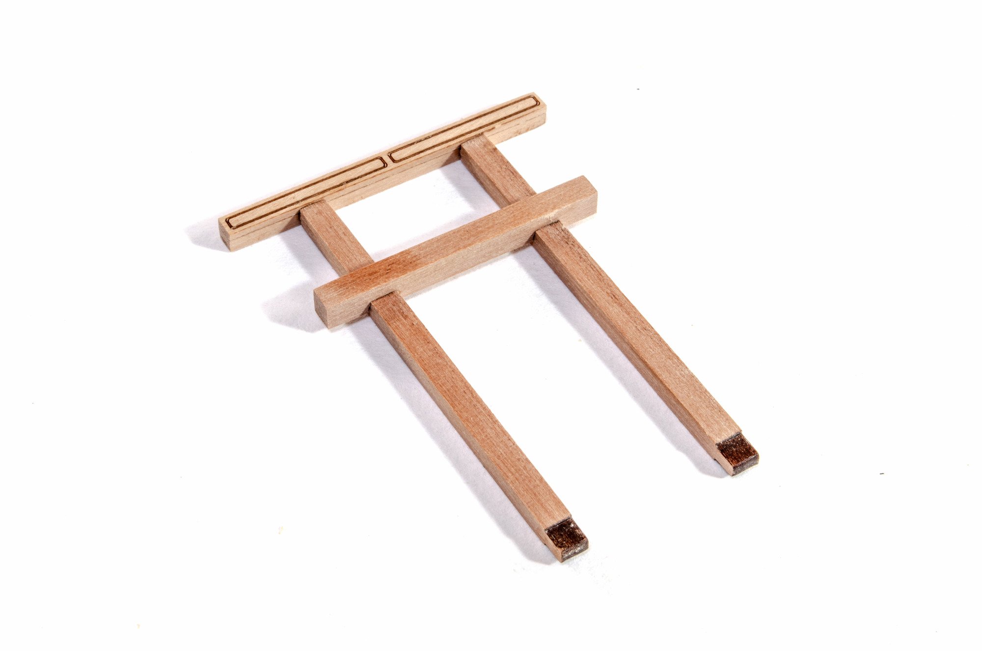
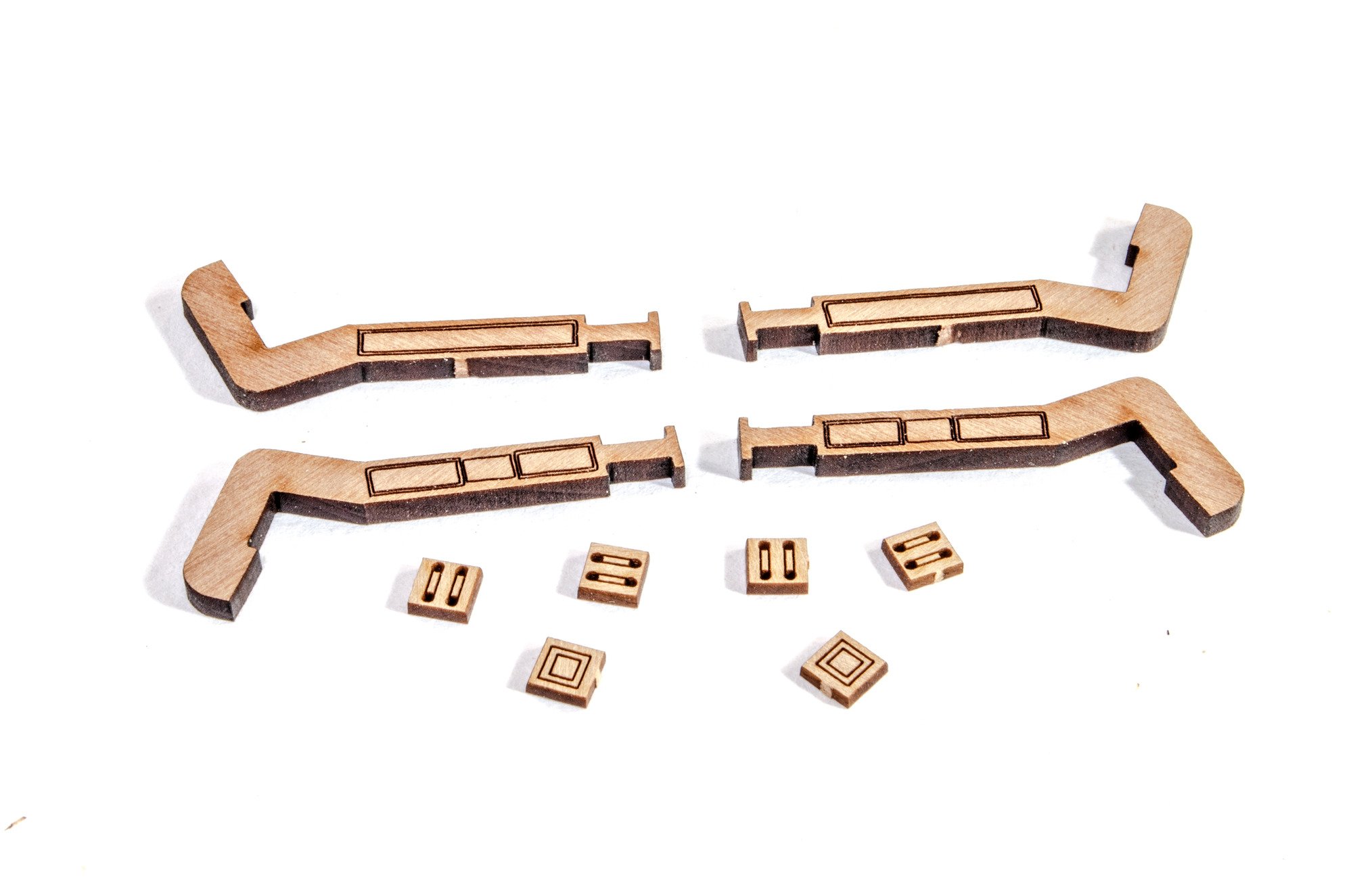
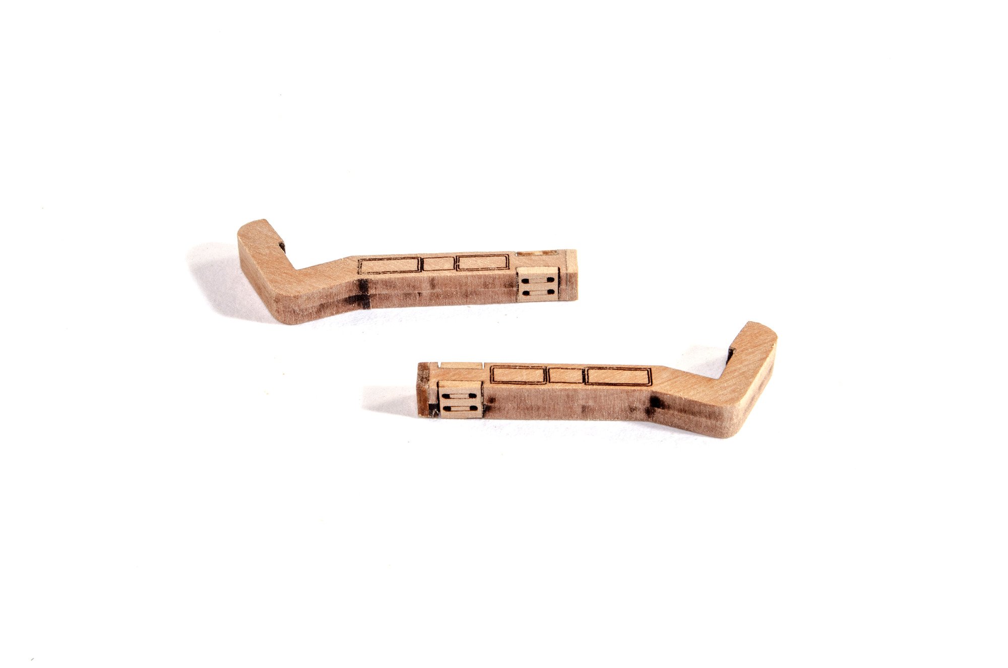
Gallows
There are two of these, slightly different. The head bar is composed of three parts which build up to make a unit which is recessed centrally to accept the vertical posts.


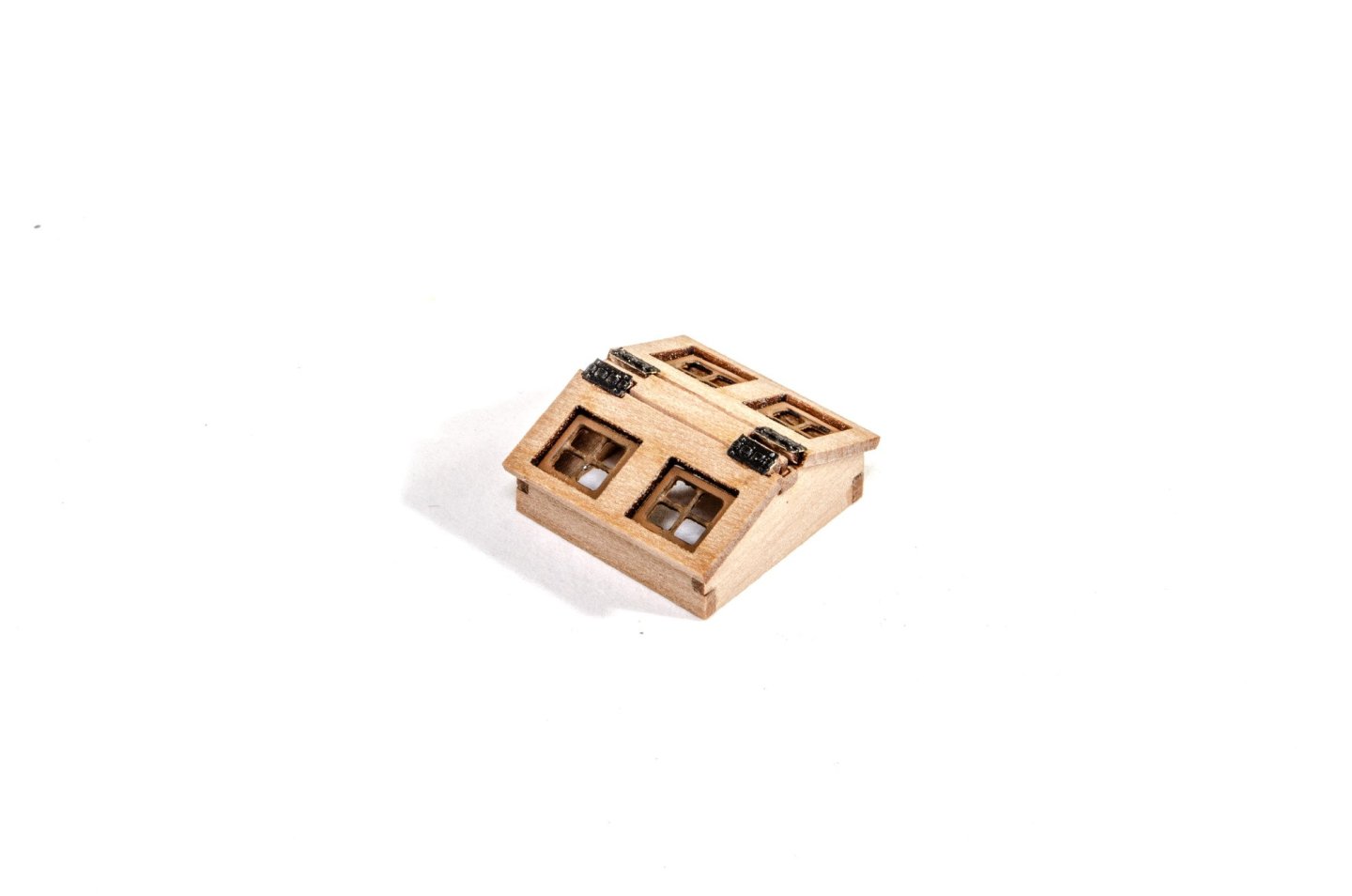
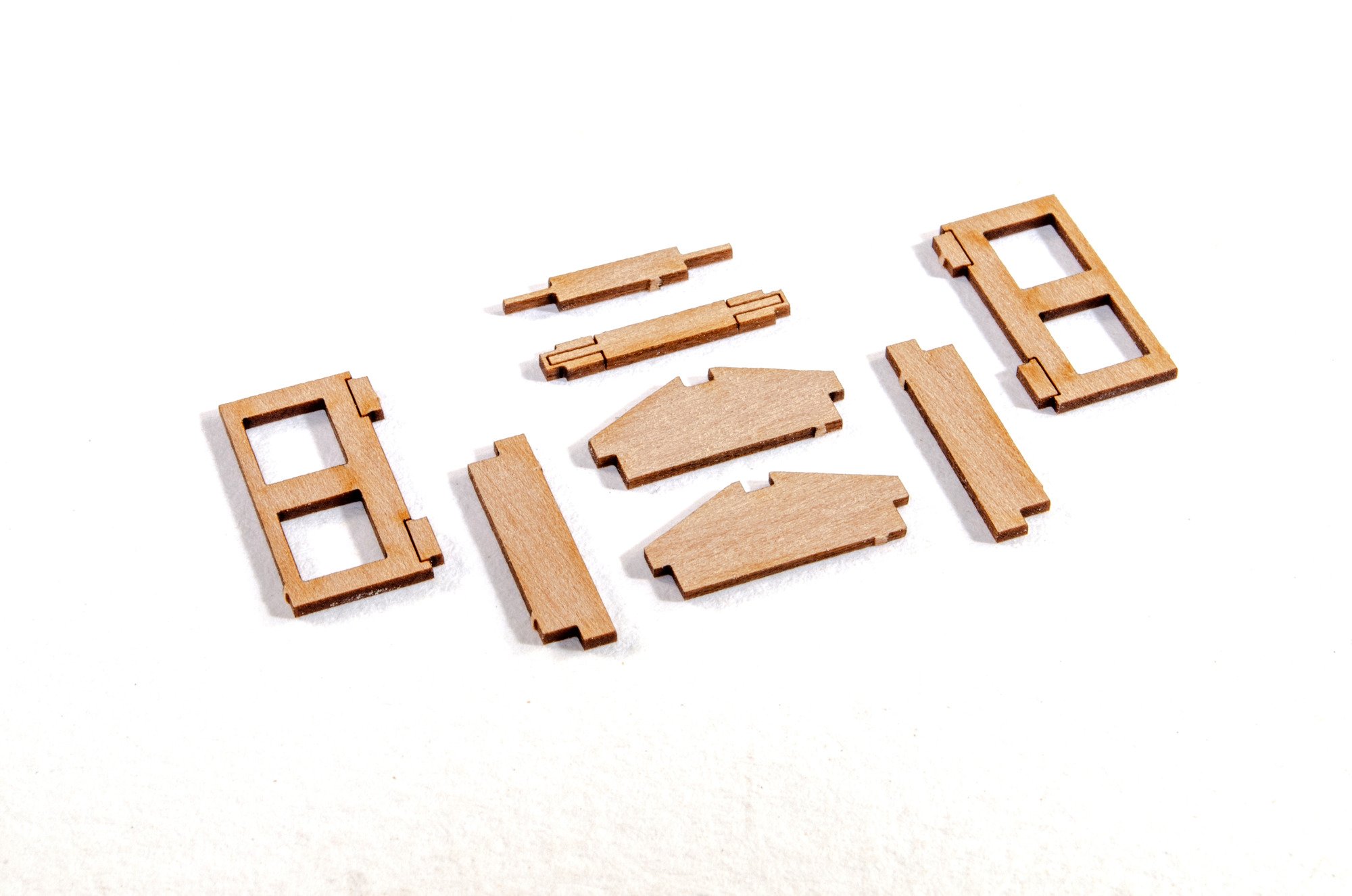
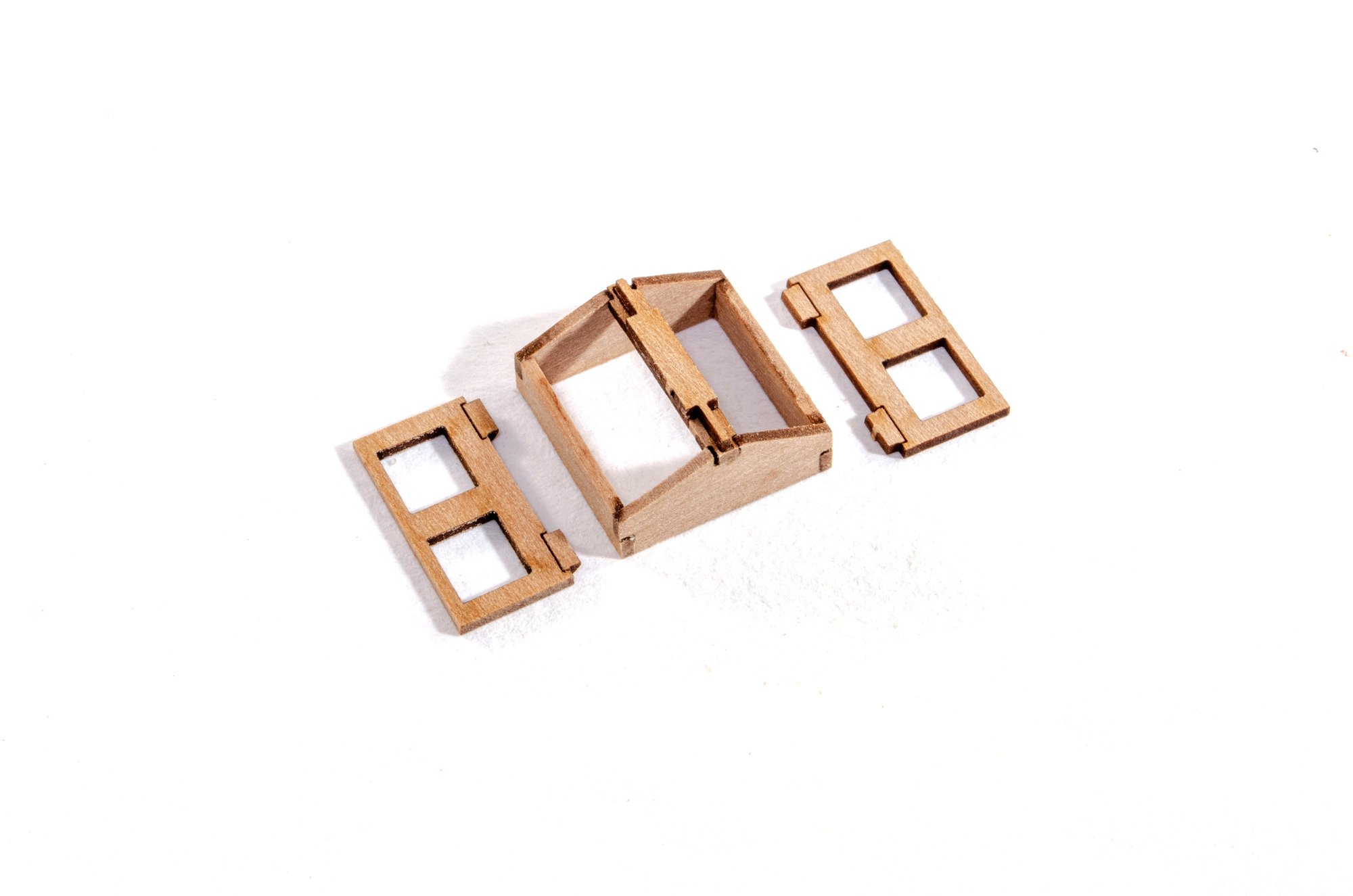
Skylight
This is very similar to skylights on some other VM kits. The photos are self-explanatory.


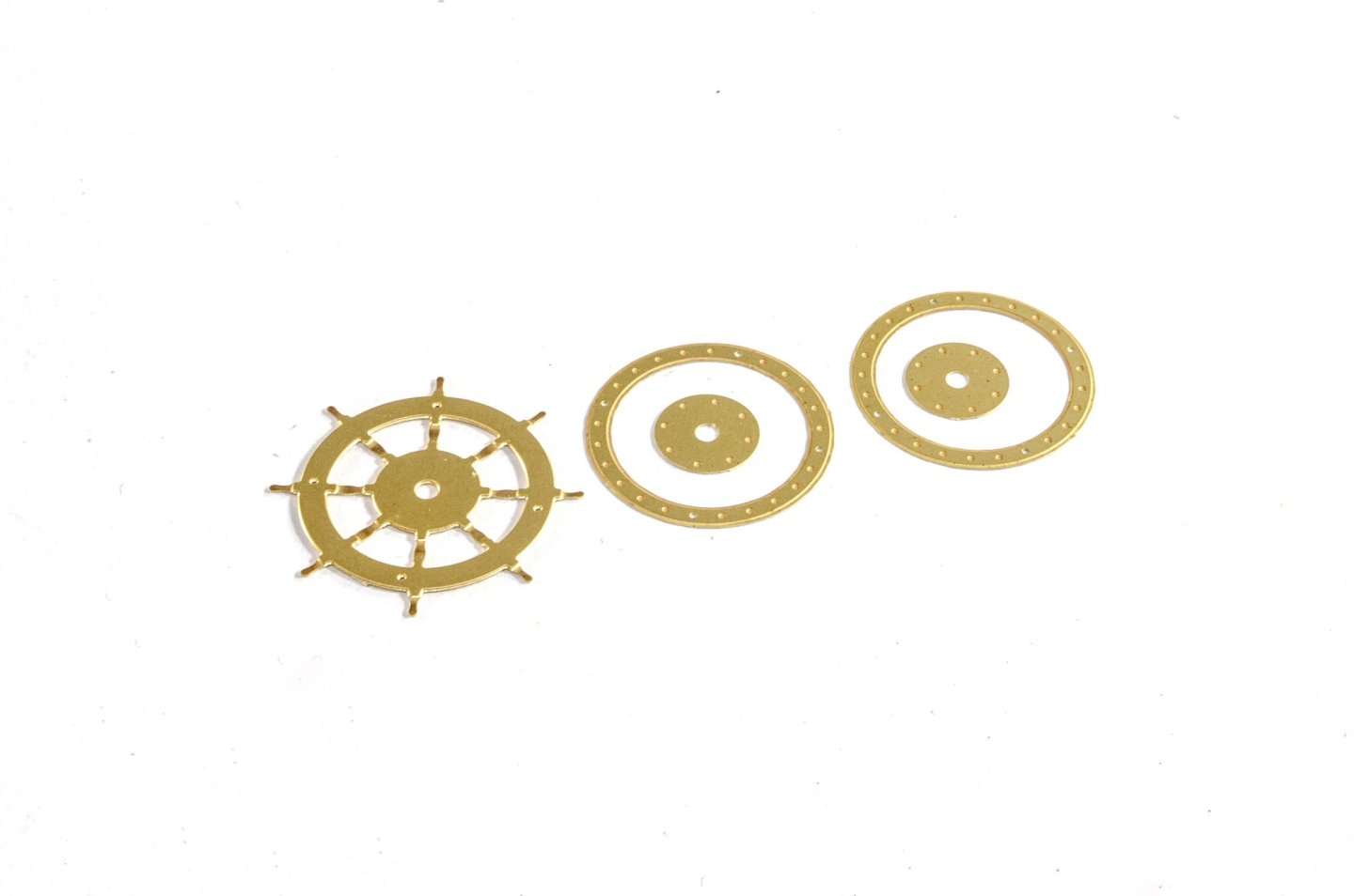
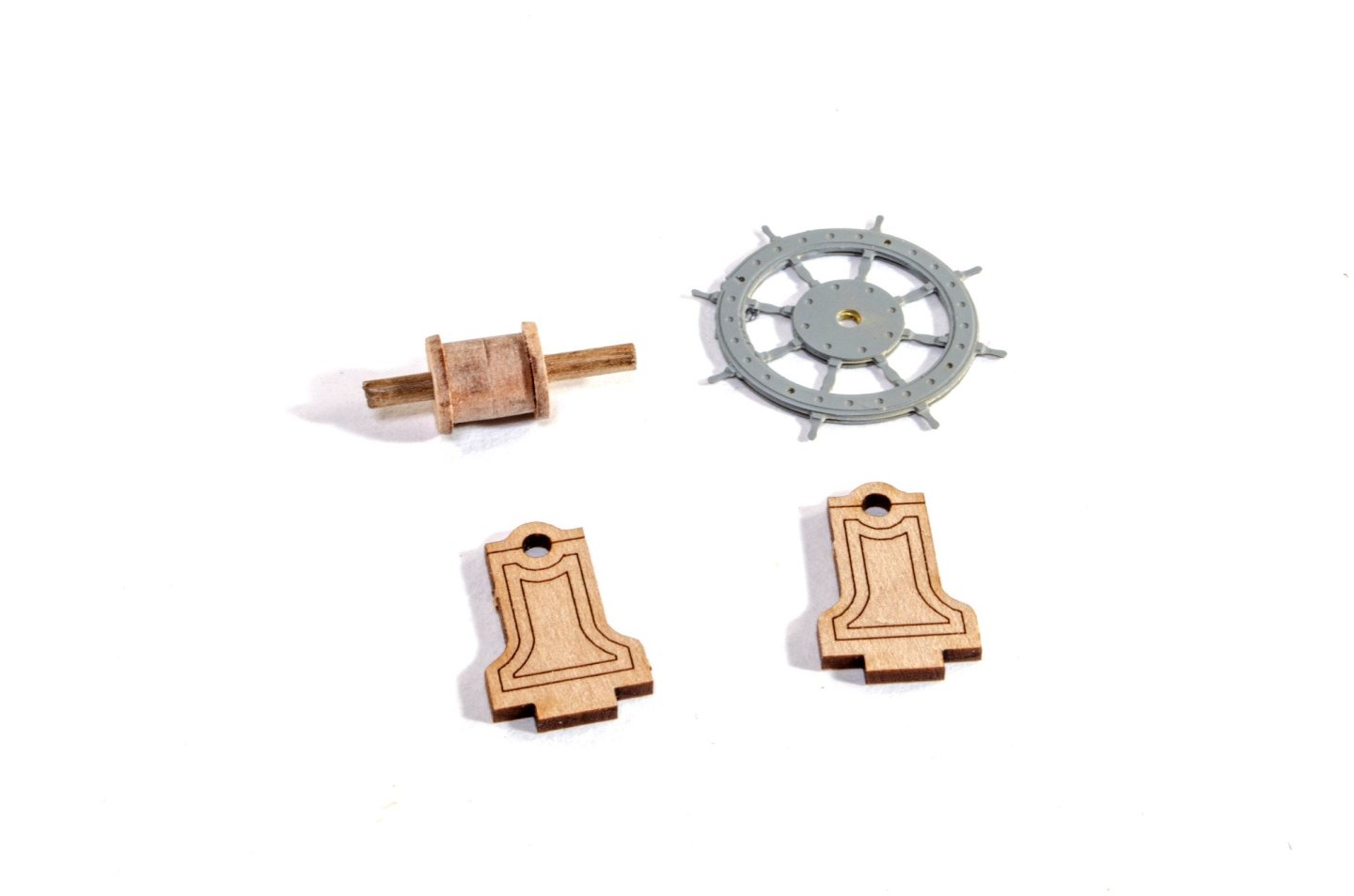
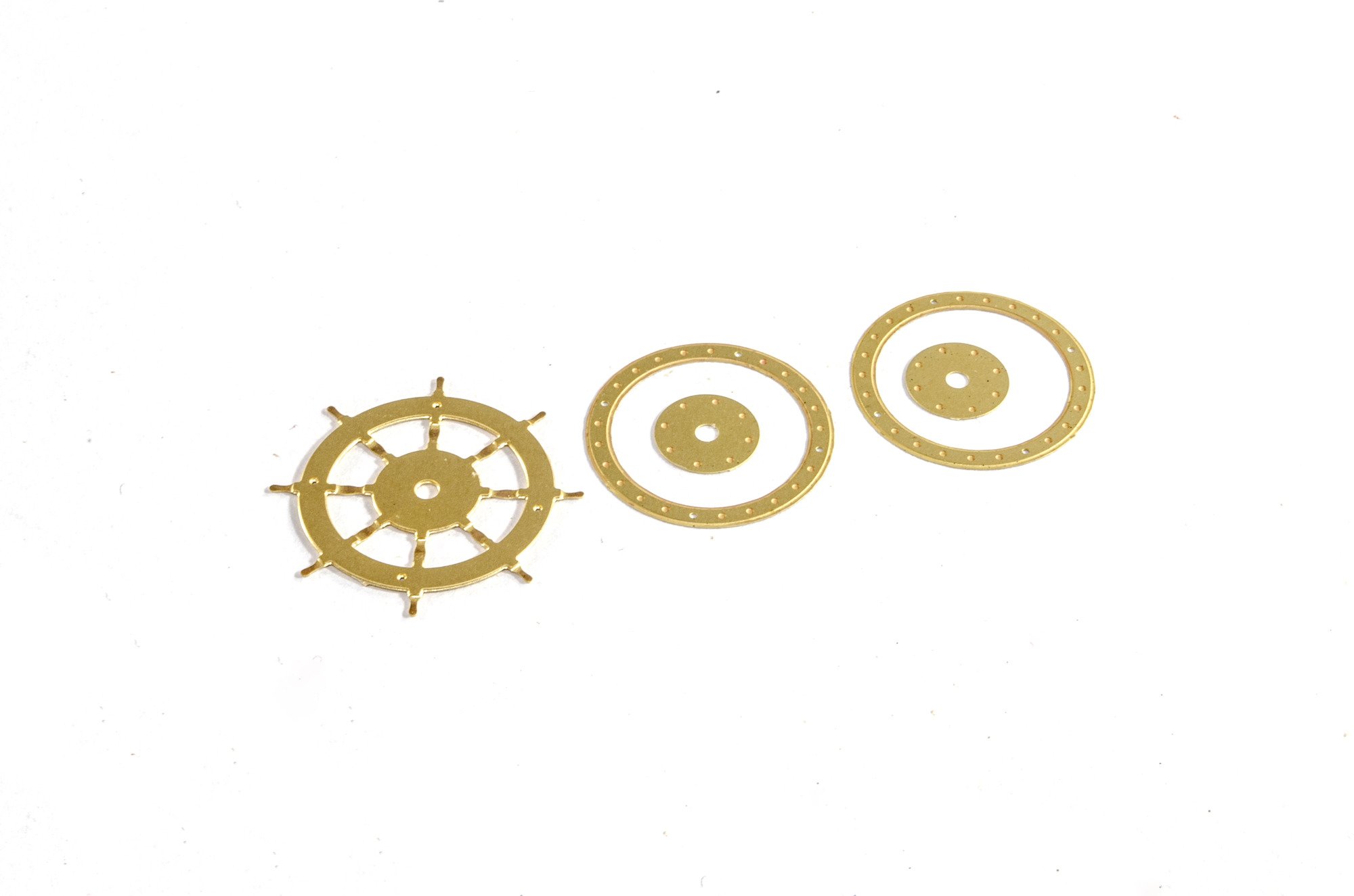
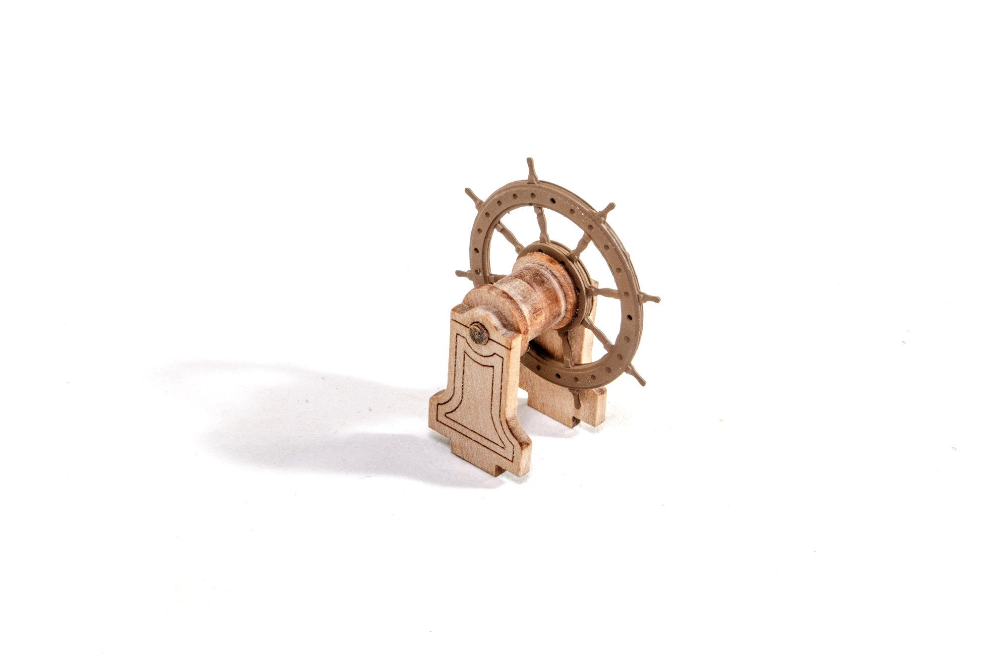
Wheel
And again, the construction of the wheel unit is identical to some other VM kits. This is centred on a drum unit which is sandwiched between the main posts, along with a photo etch wheel which is built from six parts before priming and painting in a brown colour.

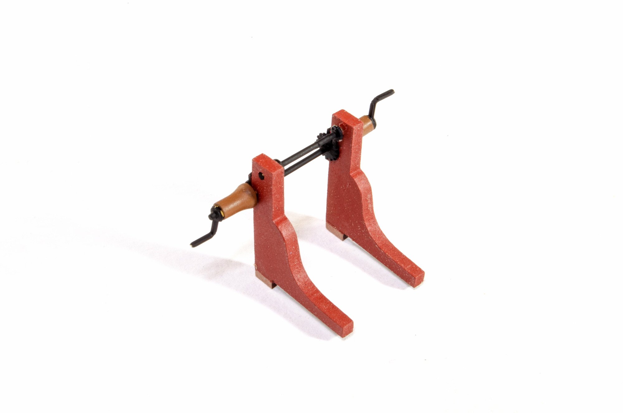
Winch
As with the bitts and gallows, this is painted red before assembly, and the 3D printed drums are painted brown. The side parts need to sit in the deck slots so the unit is properly spaced when assembled.


More in a very short while.
-
At this point, the hull still isn't faired, but that should happen tomorrow. No time lost though as all of the various fittings and fixtures are now complete, and these next few posts will show you a little of what I have done. There is a degree of work that I'm also not showing here as it's irrelevant at the moment.....such as gallows, bitts etc. painted in red.
Ok, here we go.
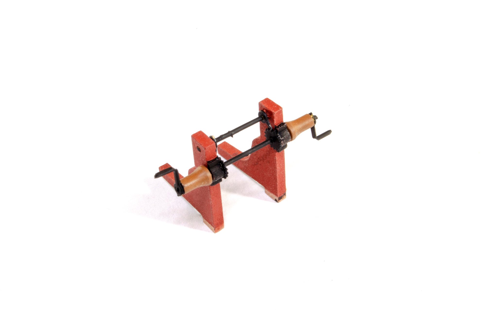
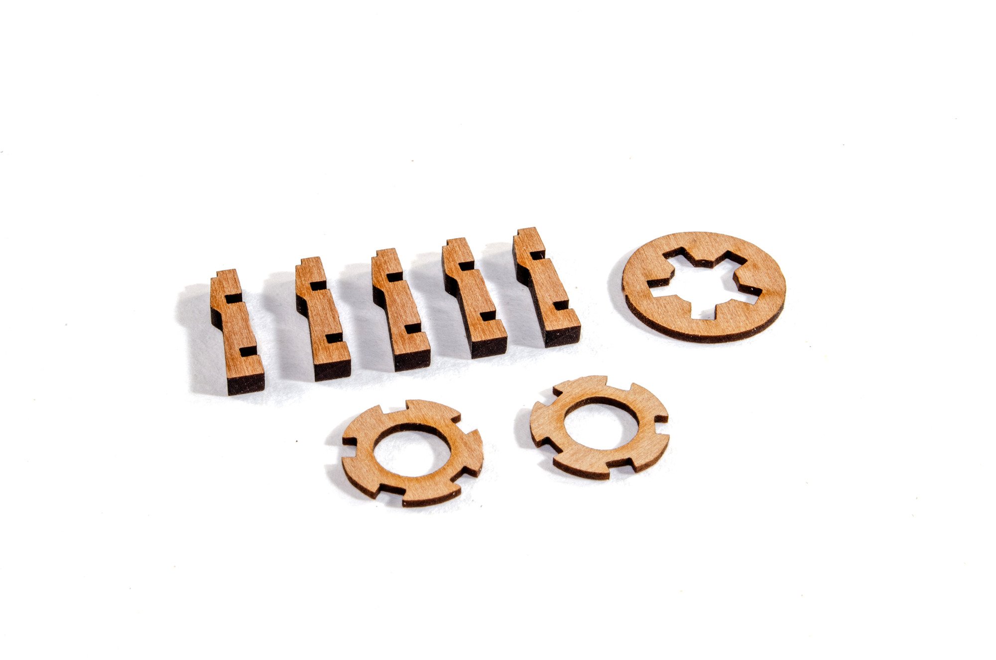
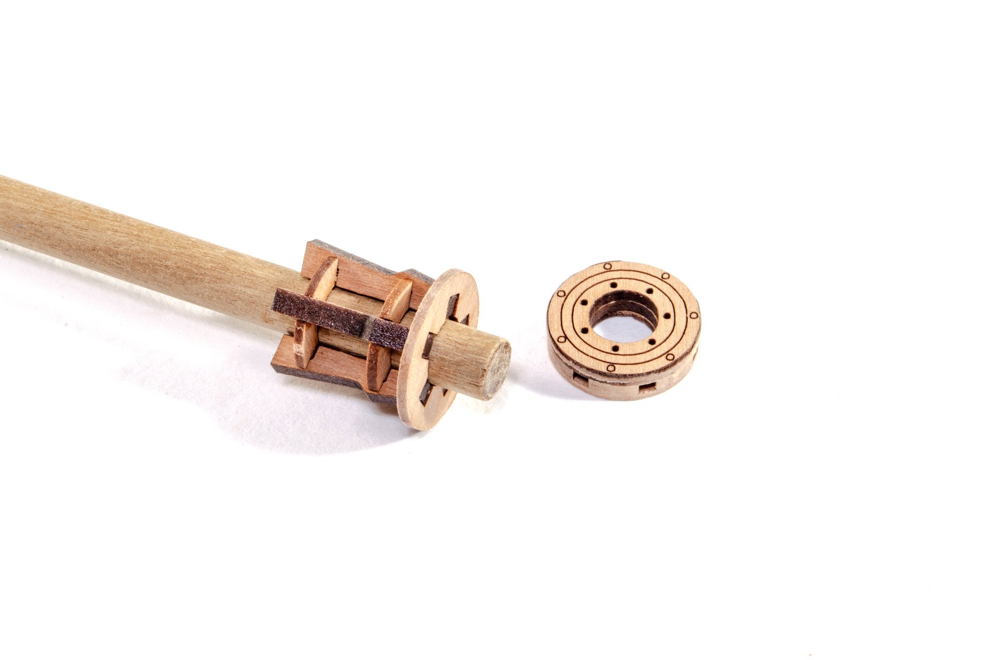
Capstan
If you've build any VM kits, then this capstan's construction will be very familiar, so here are just a few images showing it up until the painting sequence.

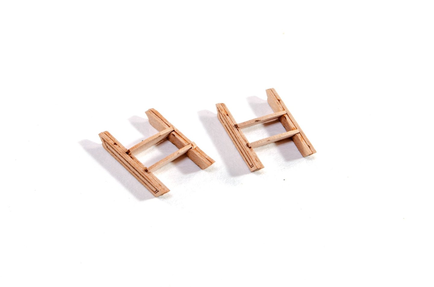
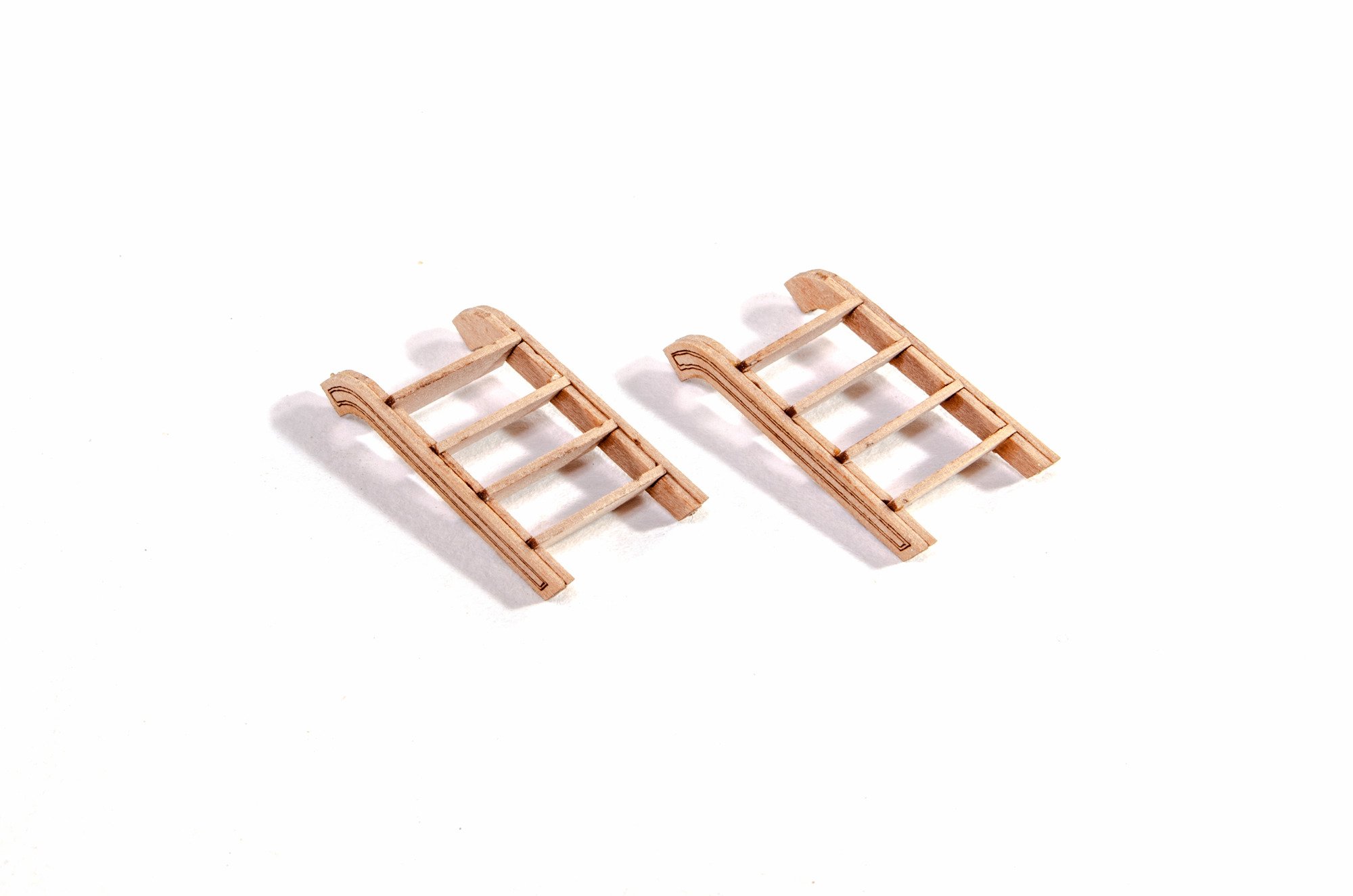
Ladders
It's the same with the ladders. These are a tried and tested formula. Harpy has six ladders of various sizes and shapes, including the ones fitted for boarding.

Final photos for companionway
As you can seem these now have the PE parts fitted. The companionway will simply be varnished, as will the skylight and wheel unit, so extra effort has been made to make this look pretty.
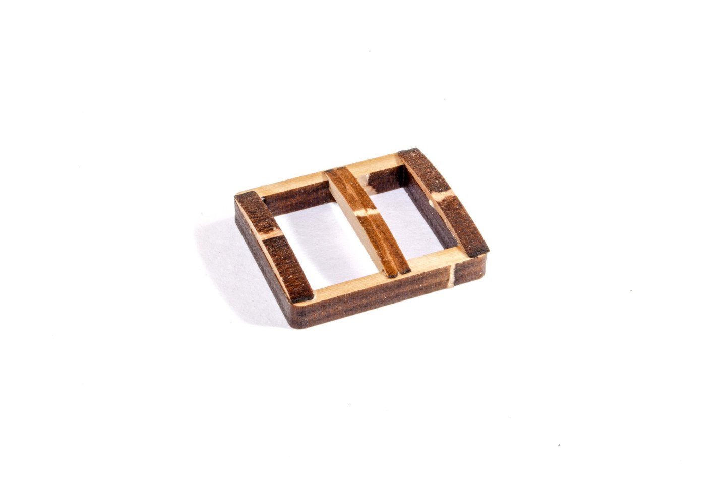
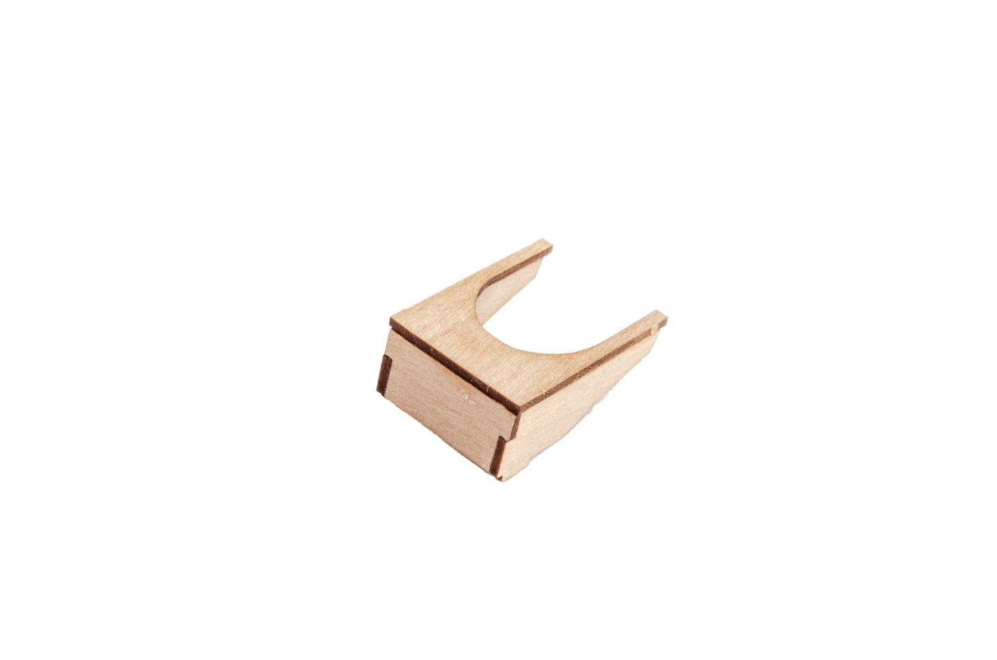
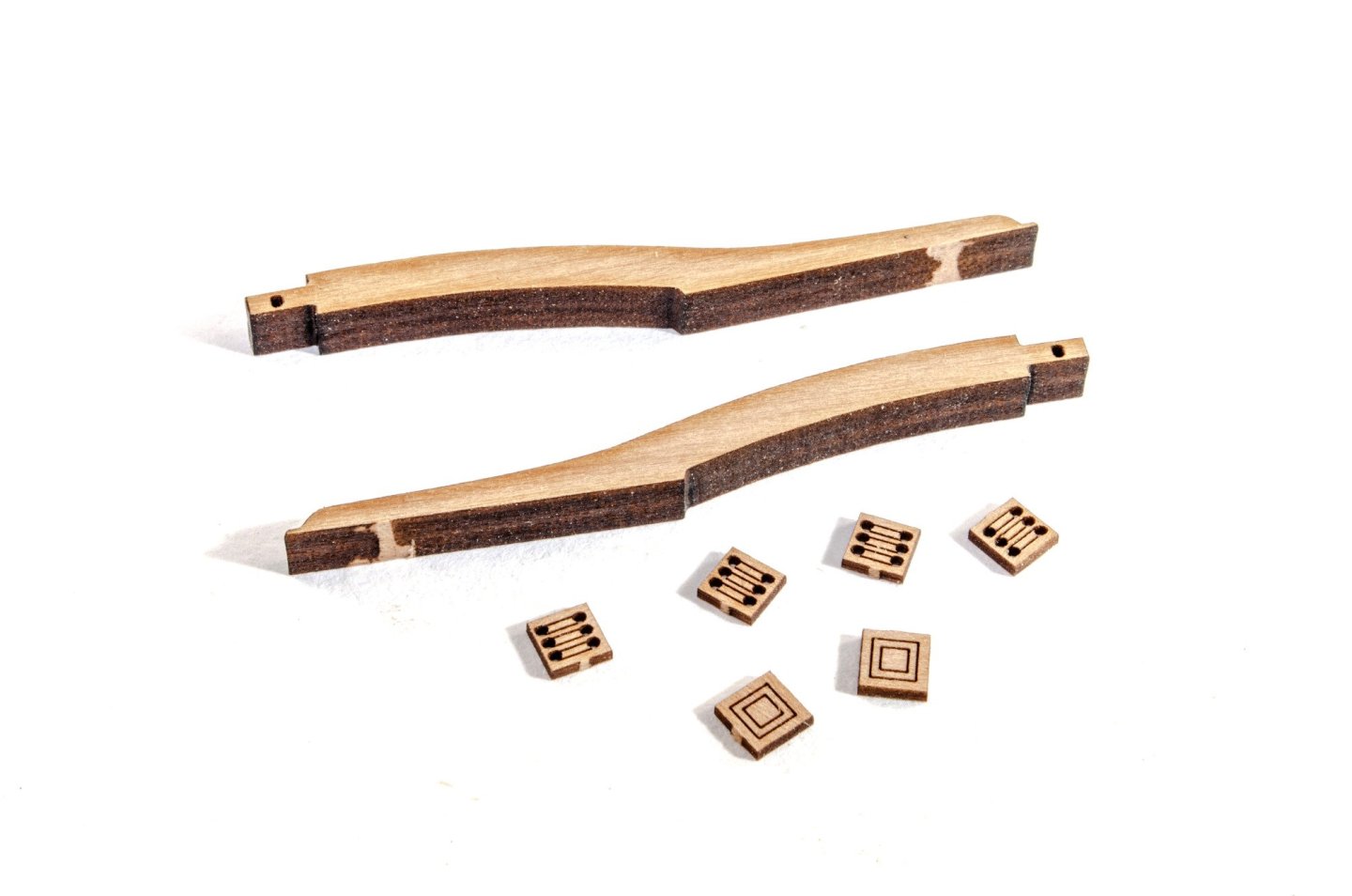
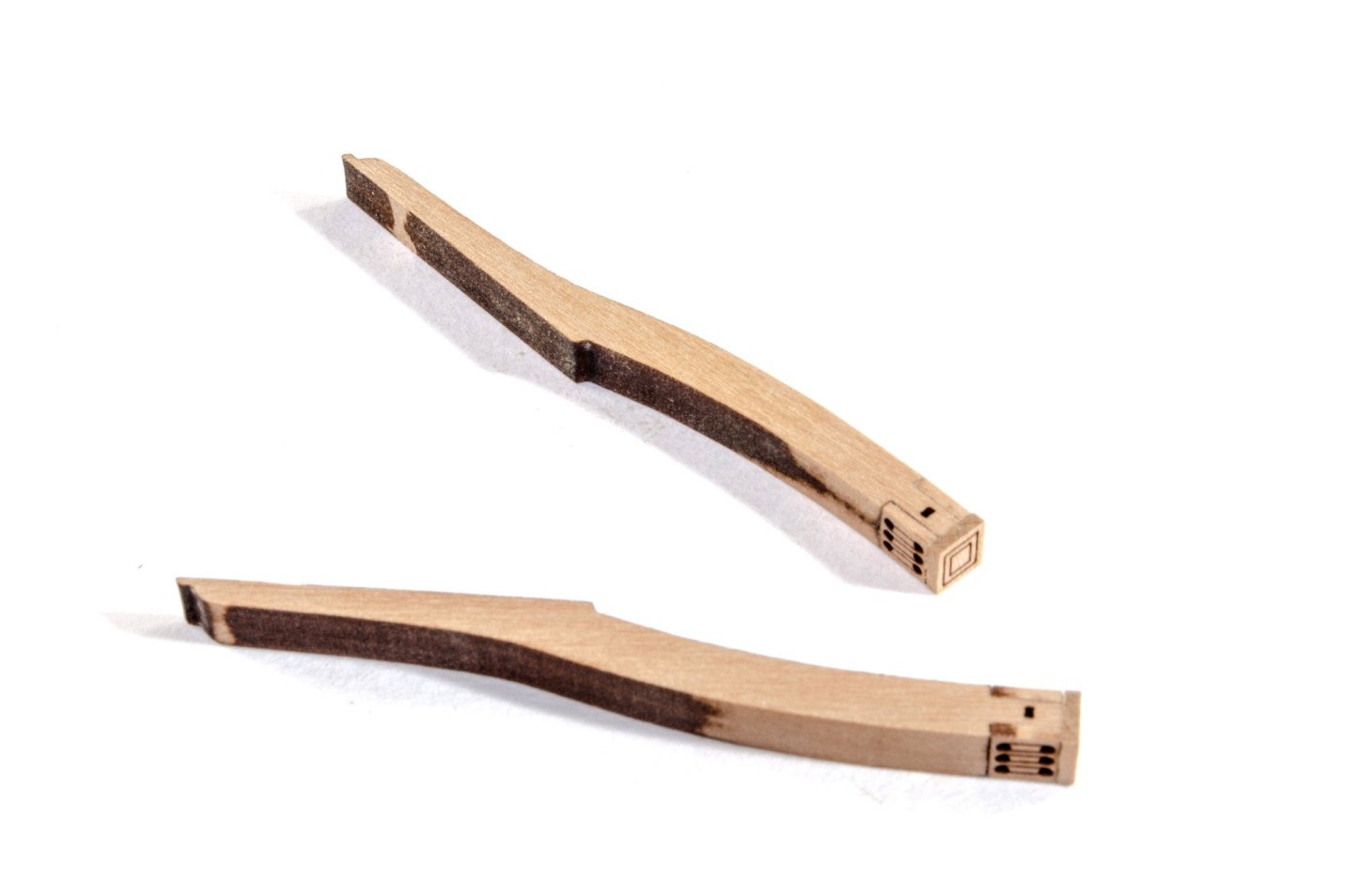
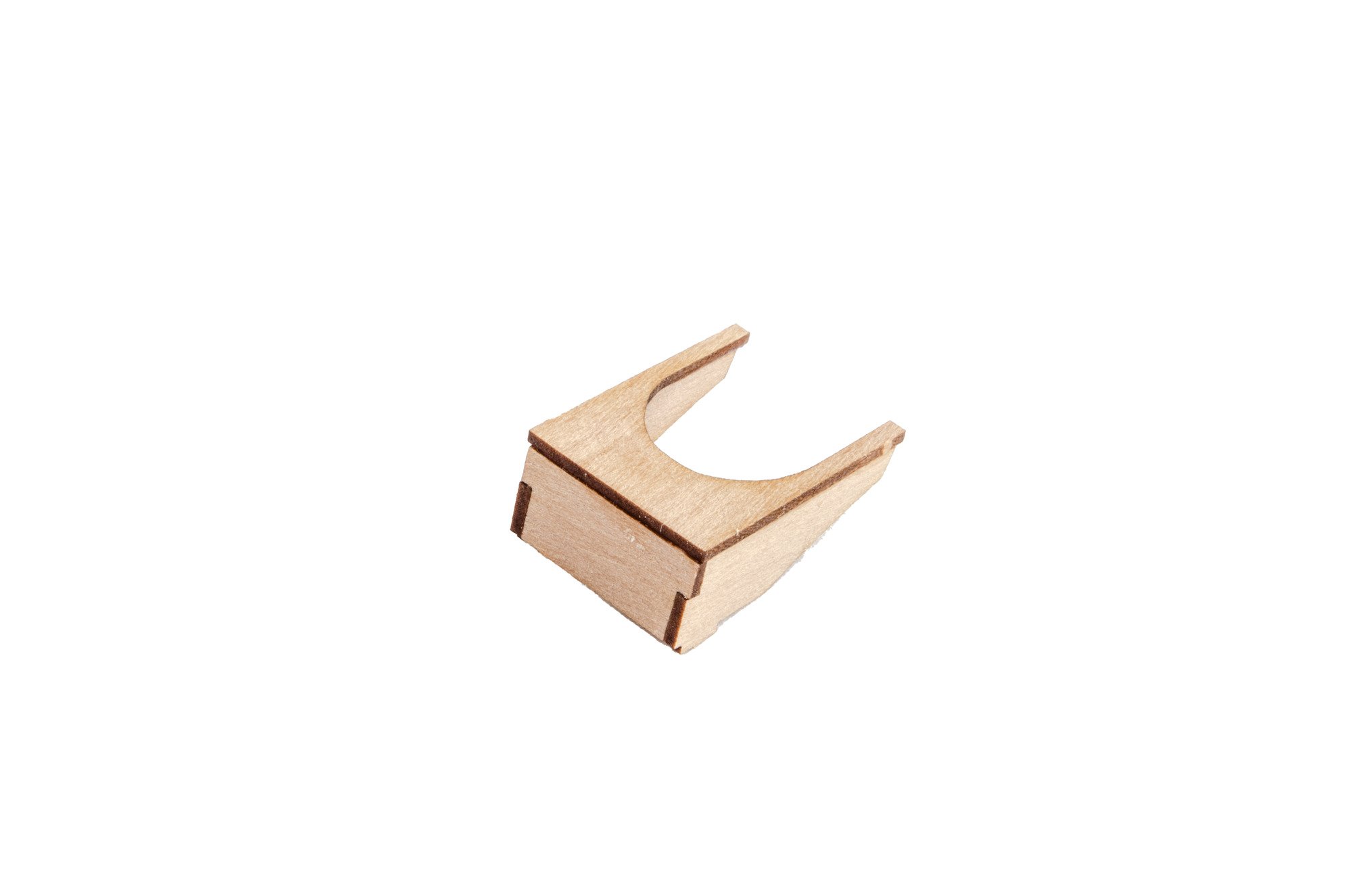
Rudder box
The original plans show something that looked like boxing around the rudder protrusion above deck. This was determined to be something that would likely have looked like this. At this stage, this just needed a nice sanding to even it up and clear up the charred ends.
Davits
These hang over the stern and provide an option for hanging the ship's boat. These are simple to build and involve adding the winch holes and end caps to the main parts. I've only cleaned these up enough to blend those parts to the main body, as the whole lot will eventually be painted black.
Catheads
These consist of two engraved parts which are glued together and then fitted with the winch holes and end caps. These will also be painted black before being fitted to the hull.


More in a moment...


7cc Double-cylinder 4-stroke Air-cooled Nitro Engine by Semto
in Non ship-related reviews
Posted
Those are things that model engine enthusiasts would normally have. This is why the starter kit is a good extra to have.