


James H
-
Posts
5,961 -
Joined
-
Last visited
Content Type
Profiles
Forums
Gallery
Events
Posts posted by James H
-
-
I can now look at assembling some of this heavy metal, as well as looking at how it'll be powered and displayed.
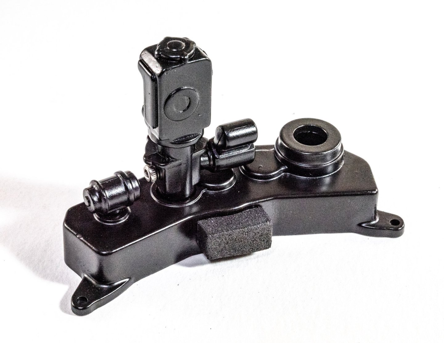
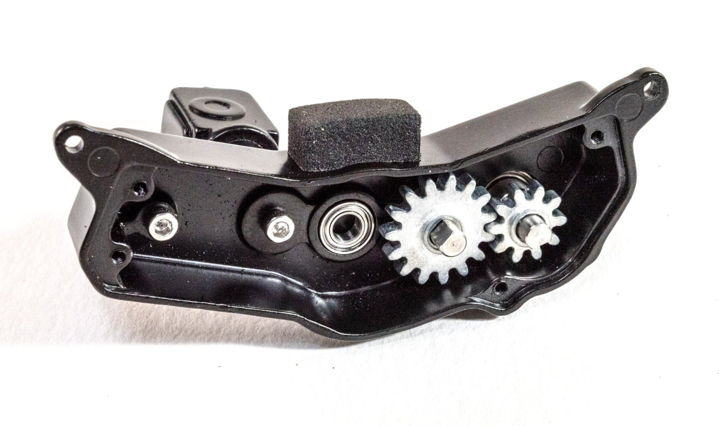
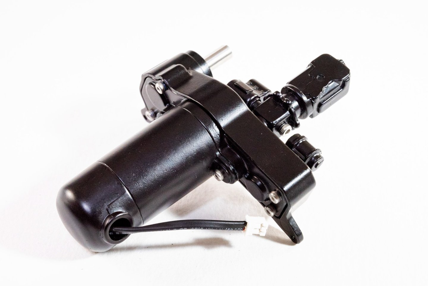
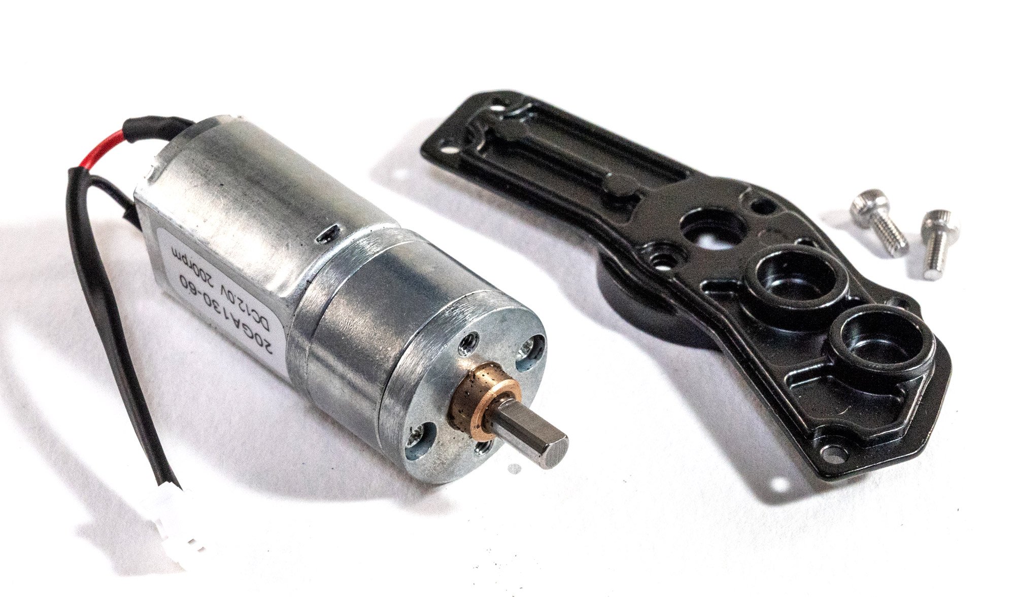
A substantial electric motor is hidden in plain view on this model, in the ancillary equipment which sits on the outside of the low pressure housing. Here you see the motor being fitted into that. You'll see the gearing too. I do pack this out with some model grease which isn't shown in the photos as it's fairly gunky.

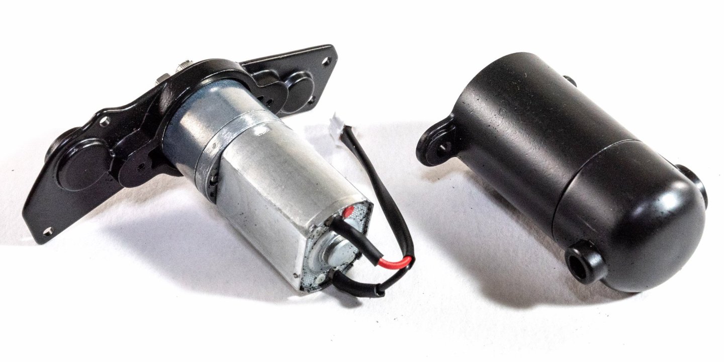

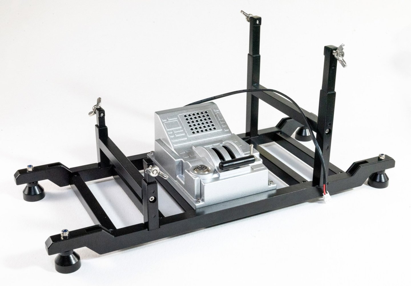
One thing that doesn't need to be assembled is the control unit. This is a self-contained unit which has a shiny button on the left for engine sound, and a toggle on the right for simple engine on/off. In the middle is the working throttle. This is connected to the unit I just built to test that all is working. I left this for a minute or two to properly bed in.
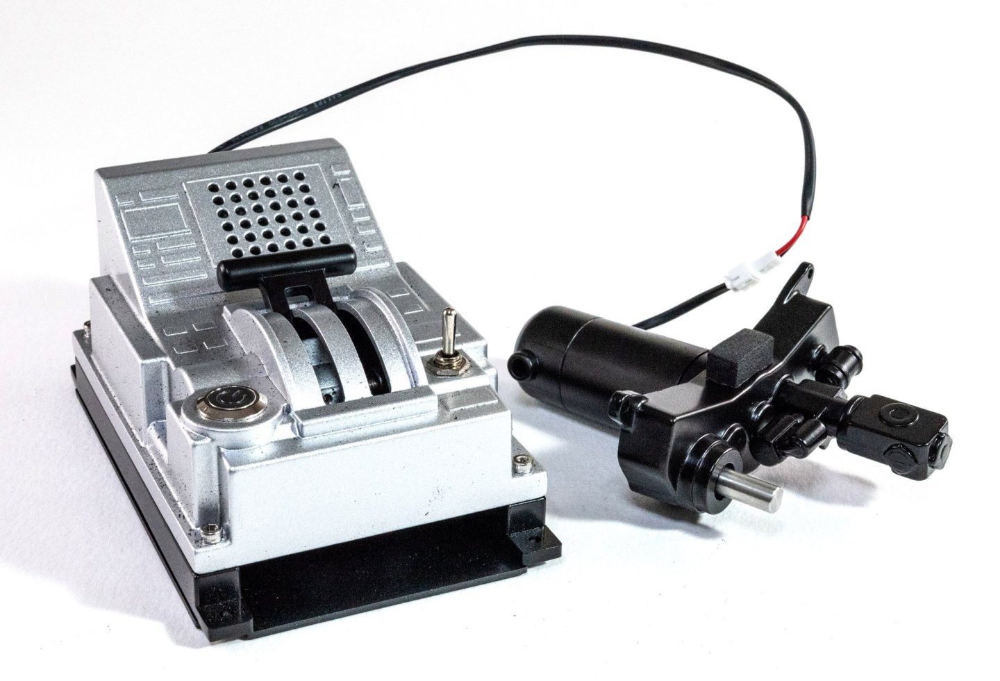
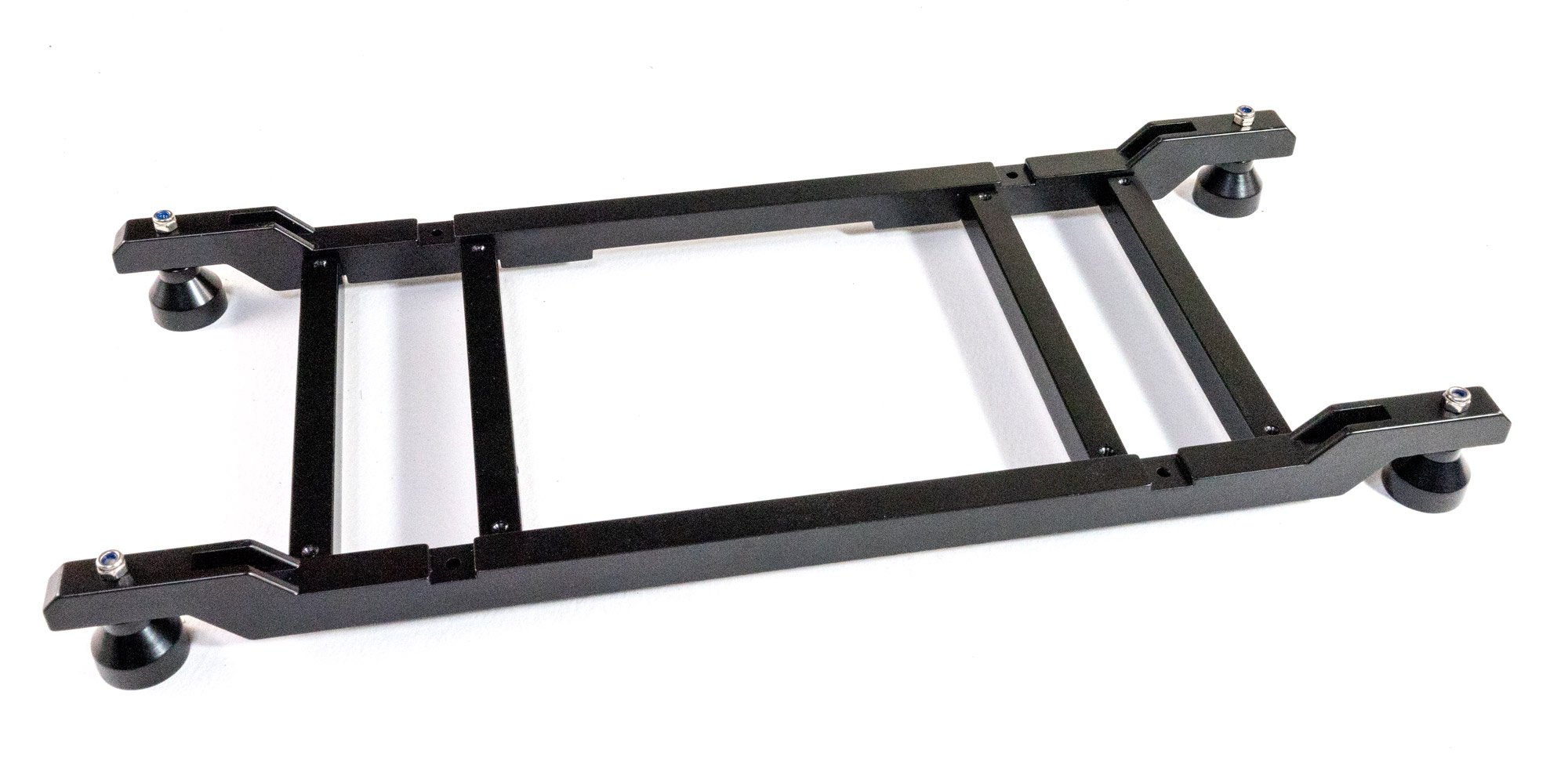
The engine test cradle is now put together and the control unit bolted into position.

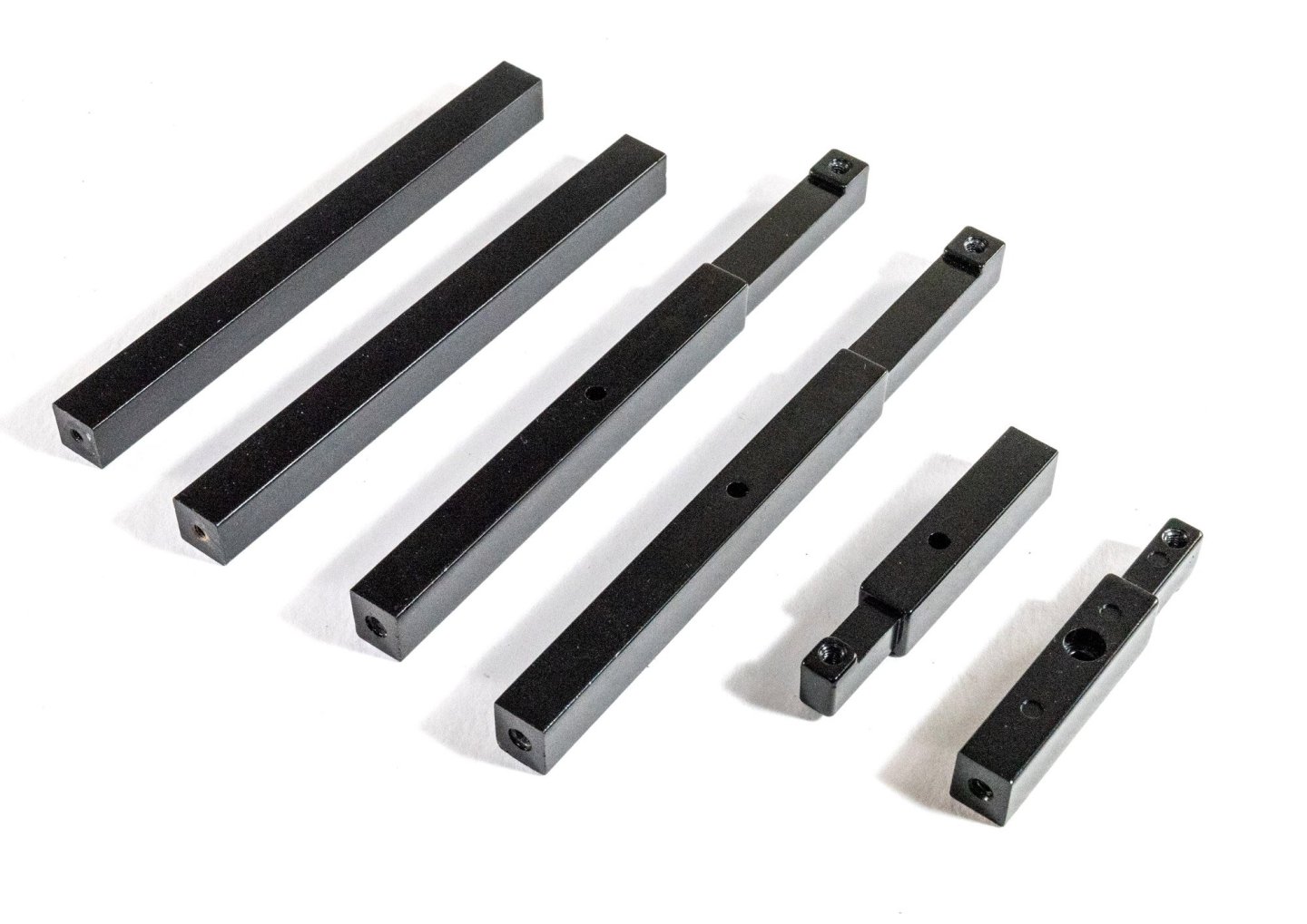
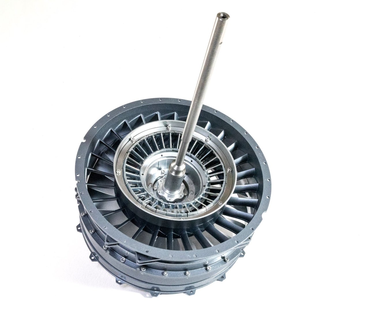
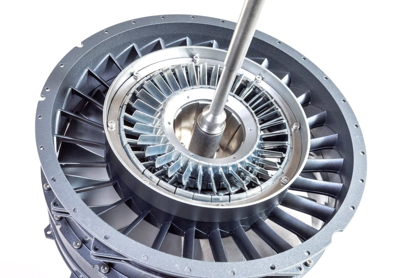
The engine needs to be built up before it can be mounted. The forward low pressure rings are now bolted together with a mix of both locking nuts and regular nuts with thread-lock applied.
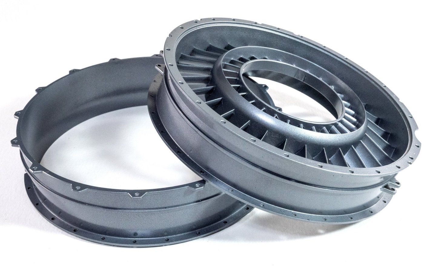
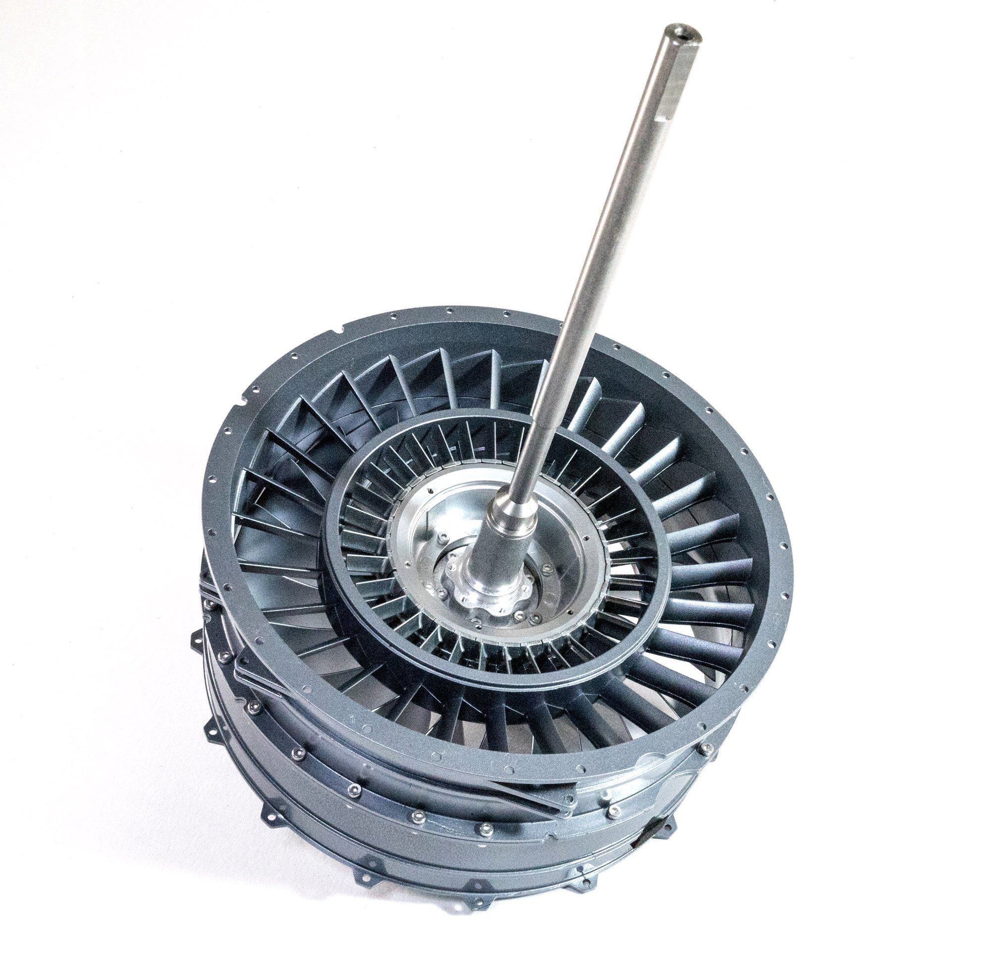
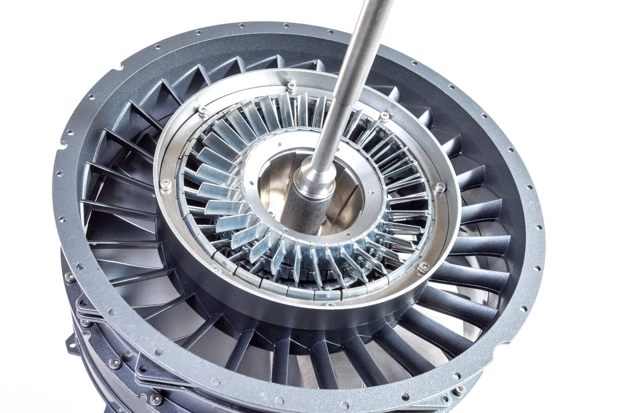
Enter the large low pressure fan I built at the beginning. This is now slid into position and a high pressure rotor bolted into place from the rear.

More rotors now slid into position.
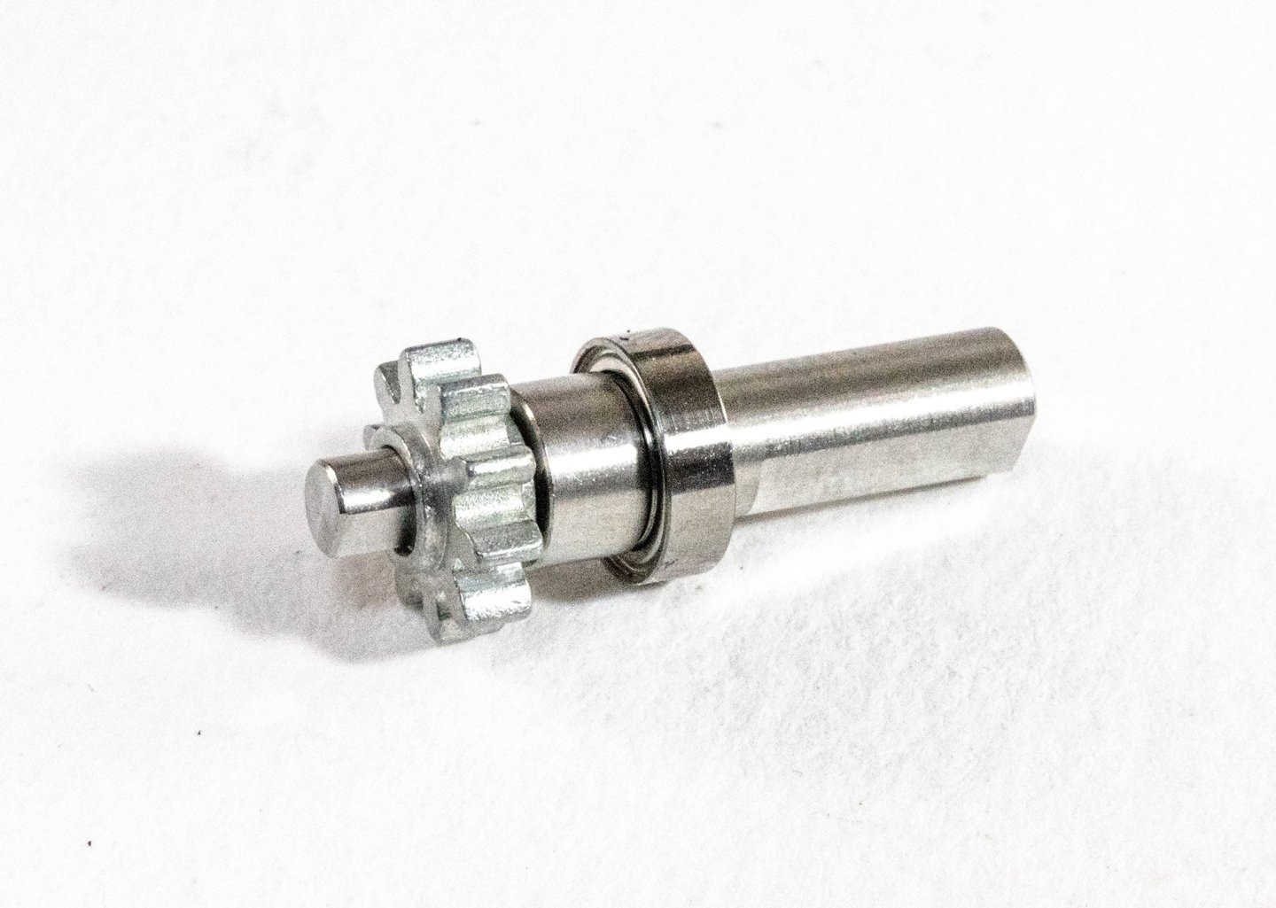
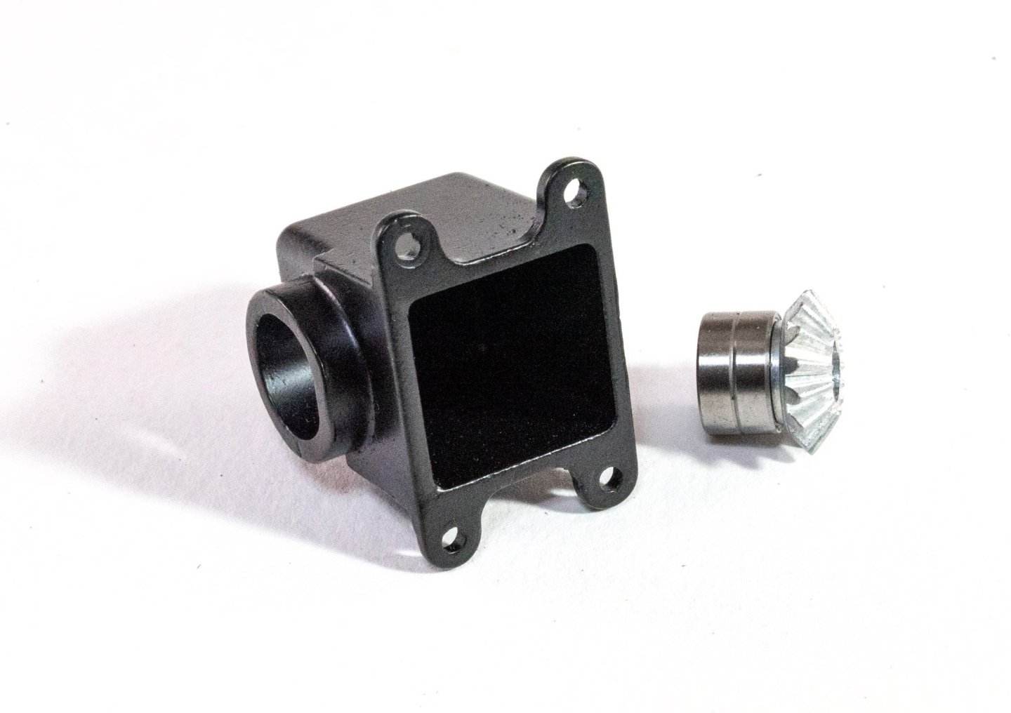
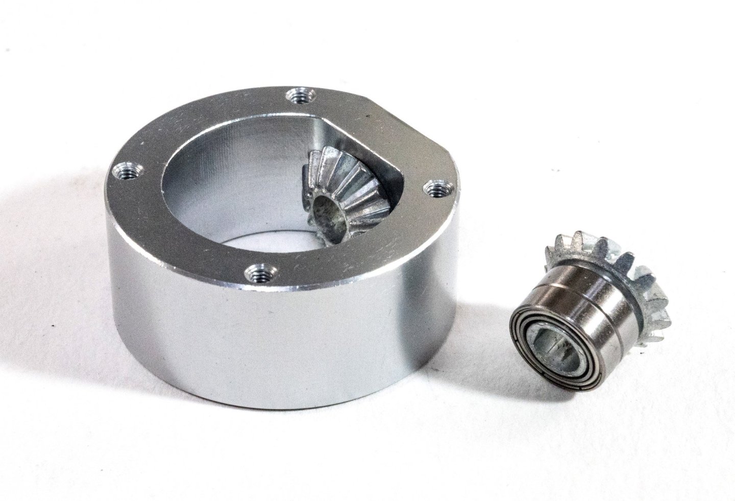
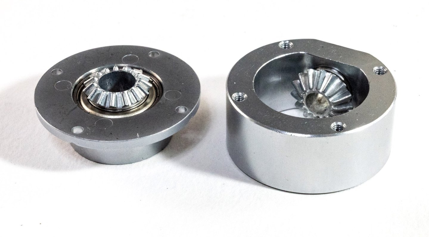
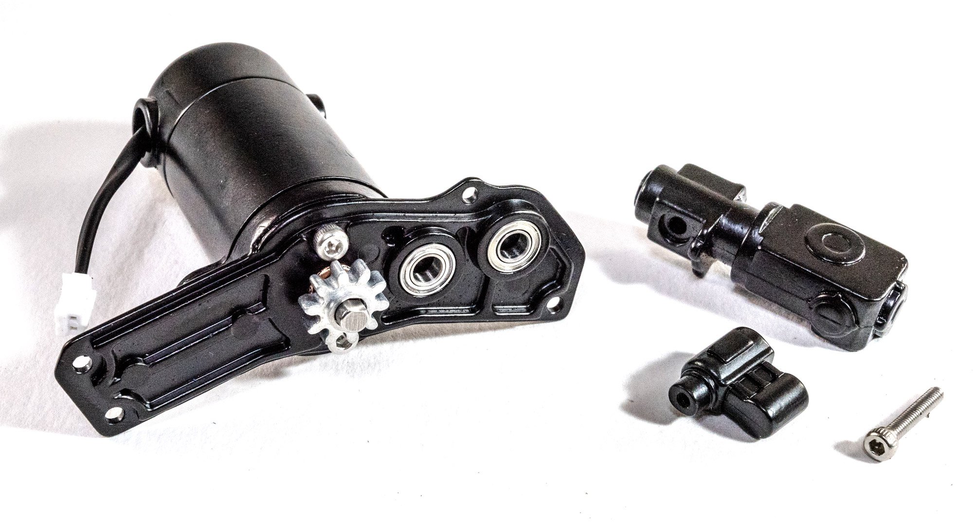
The electric motor needs to have a gearing system in place which turns the rotation through 90 degrees towards the main fan shaft. This little unit is now built and greased and then inserted into the intermediate green casing which will be seen in the next and last update.
...to be continued.
-
On 6/2/2024 at 10:37 AM, Lohengrin said:
This seems to be an older post but I would still like to say thanks for such a thorough review and break down of the kit!
I cannot wait to get my hands on this 🥺It's never a problem to reply to an older post.
I hope you share your build with us
")
Jim
- mtaylor, Paul Le Wol, Ryland Craze and 2 others
-
 5
5
-
This is mine, from Amazon. What I like about this one is it's quite tall at its upper end and can also sink low enough for a regular desk.
https://www.amazon.co.uk/gp/product/B0BFLRH7WJ/ref=ppx_yo_dt_b_search_asin_title?ie=UTF8&psc=1

- Desertanimal, aaronc, thibaultron and 2 others
-
5
-
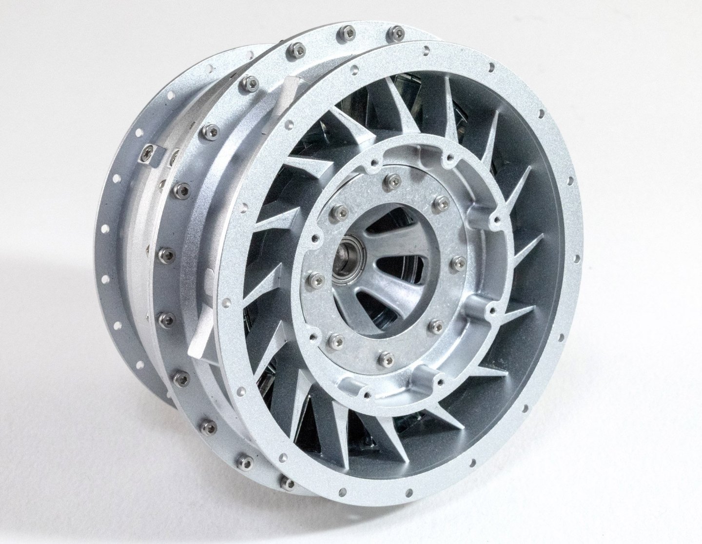
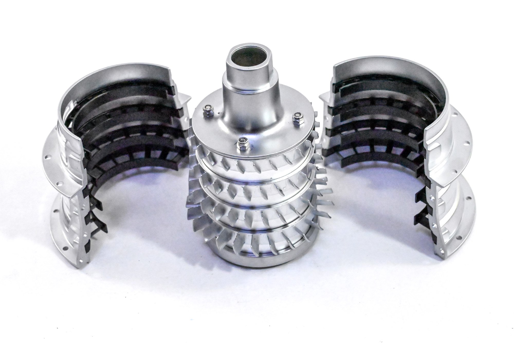
Assembling the high pressure compressor
The previous two assemblies cab now be fitted together. Whilst one of these rotates within the other, there's no need to add any lubrication as the centre assembly will rotate on the main drive shaft and is clear of the outside casing.

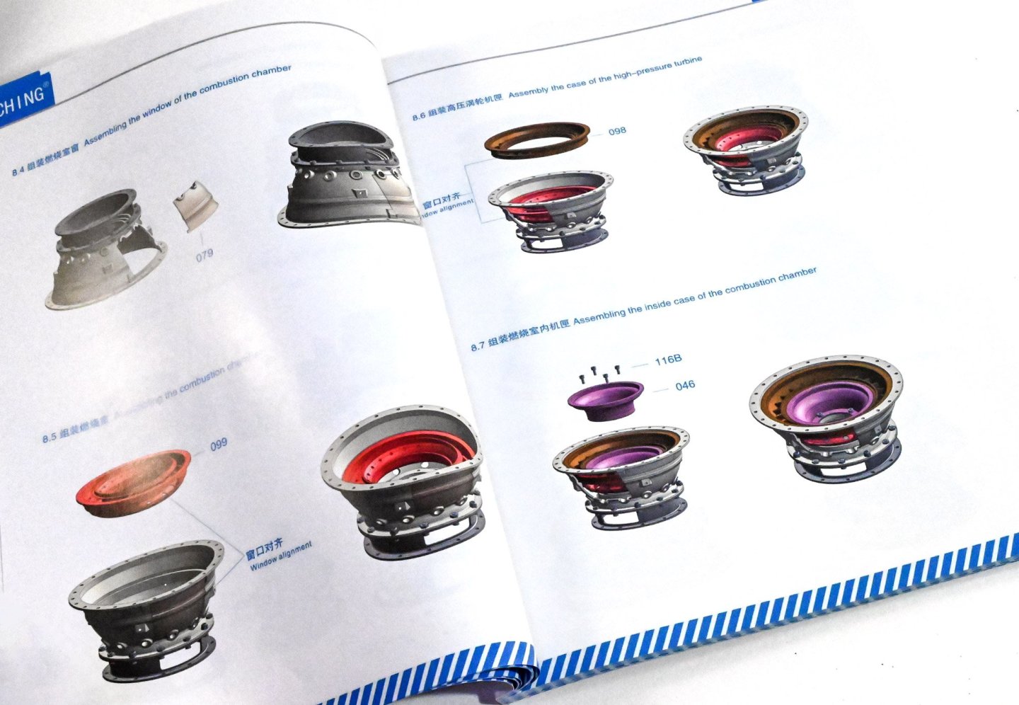
Combustion chamber
The first assembly also has a cutaway window so the modeller can see the interior parts while the engine is running.
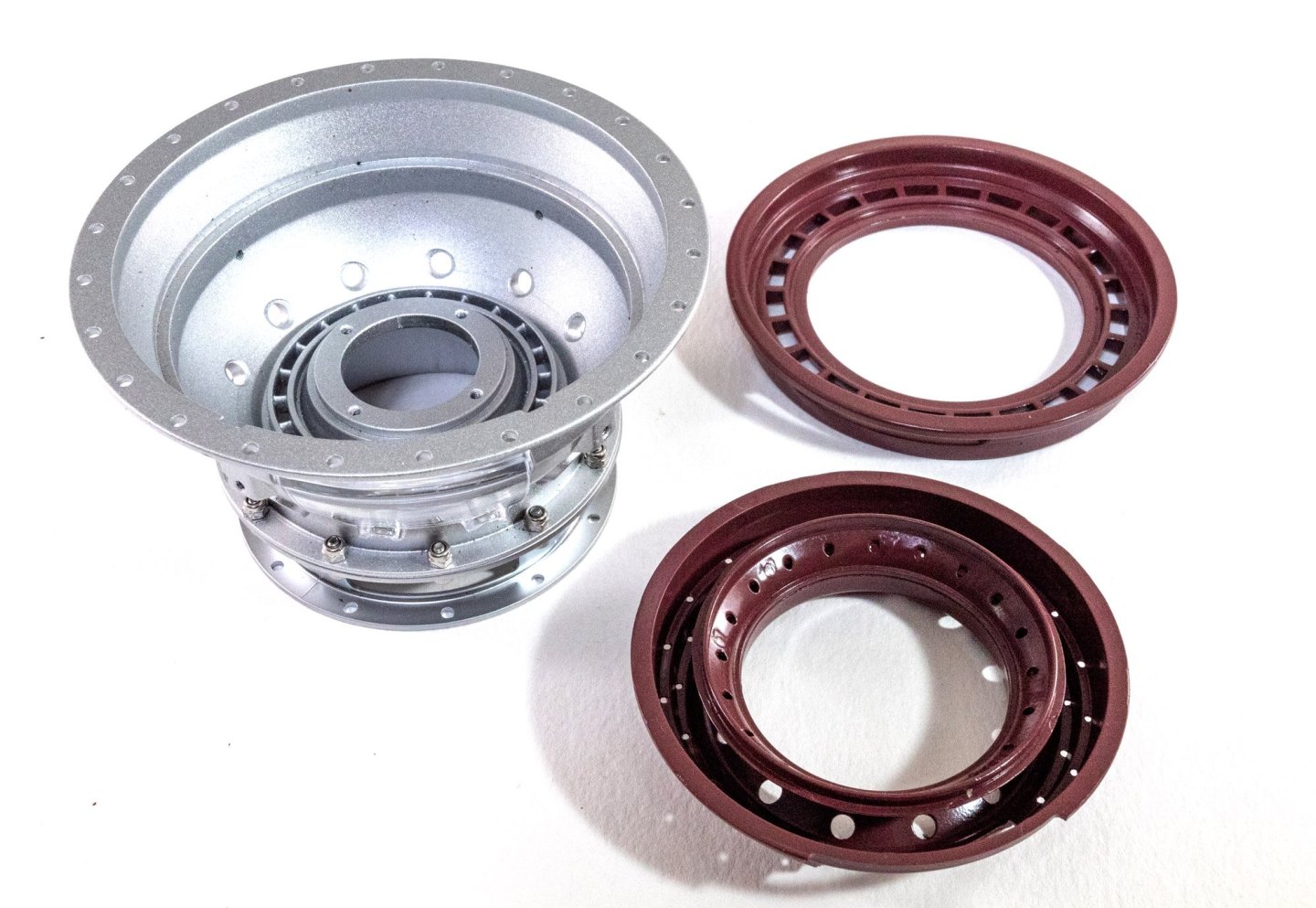

A few small external details are now added to the completed chamber, namely the fuel branch pipes and distribution ring.

High pressure turbine rotor
You'll start to see a pattern of seemingly similar items being built. The assembly of these is very, very similar, even if the completed units are physically different.


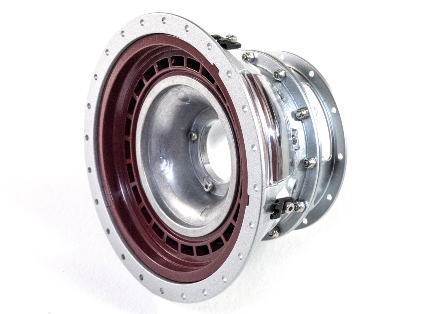
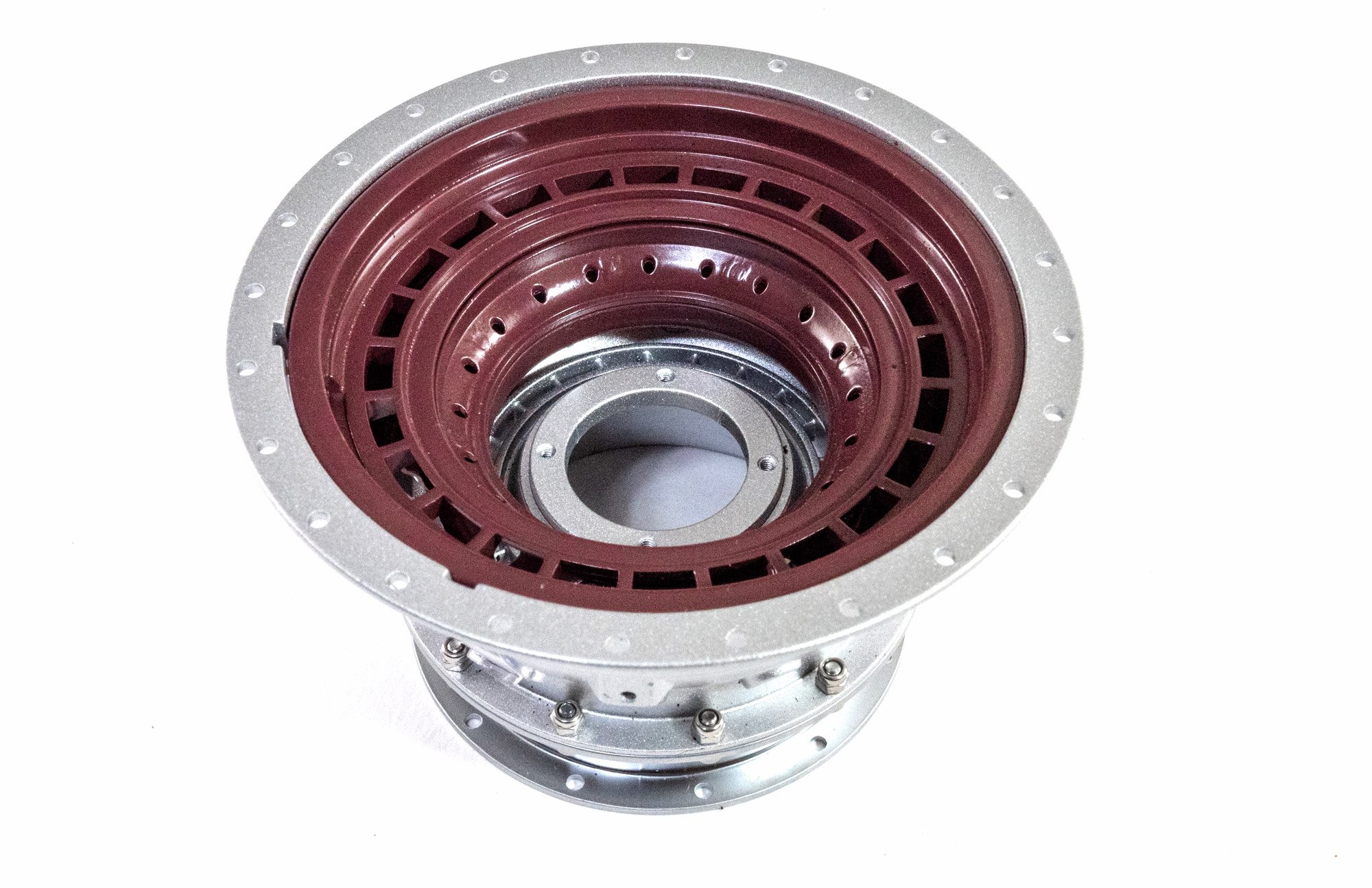
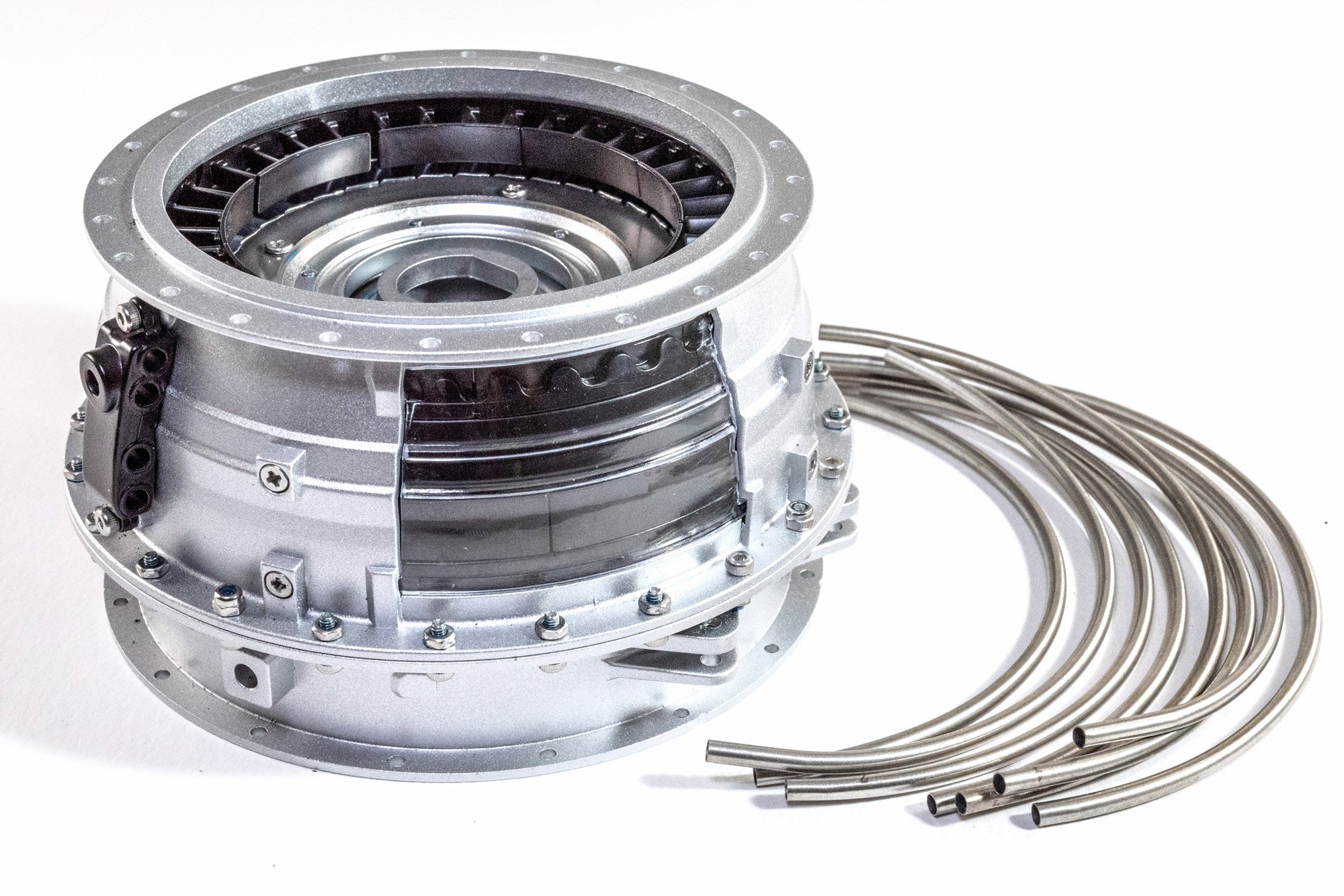
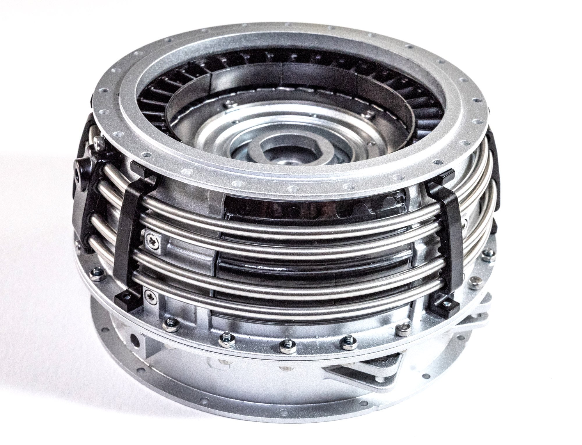
Low pressure turbine case
As before, this has another viewing window and there are more stator blade elements that sit within. These are held in place by a black ring which sits atop them and is secured by four screws from the outside of the casing.
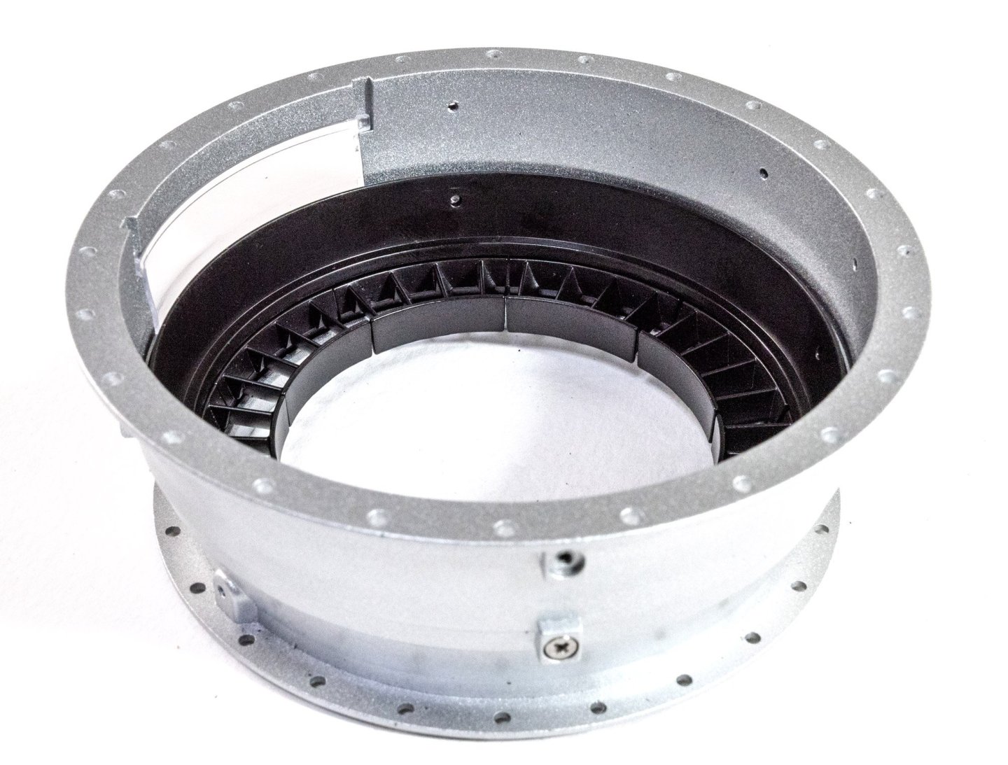
The various stator parts can now be fitted in conjunction with the rotary units
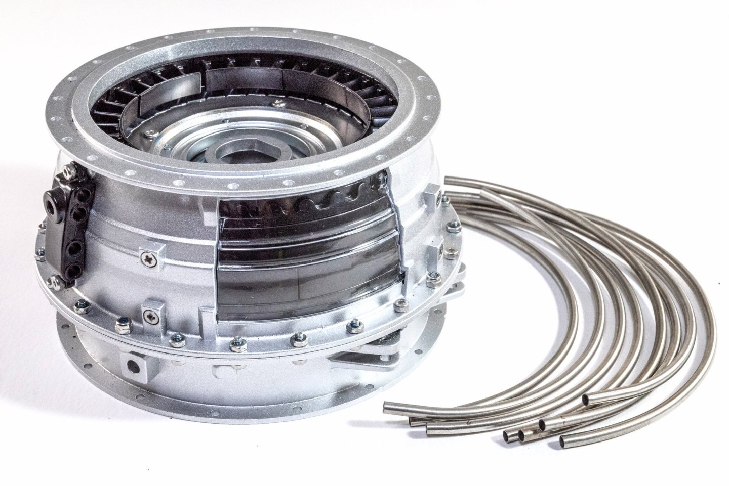
Now a large section of the case is fitted onto this unit, trapping the rotors and stators within. All of these circular assemblies are first secured with a small number of bolts and locking nuts. When everything is guaranteed to be central, the remainder of the bolts are fitted with regular nuts. Again, all are thread-locked.
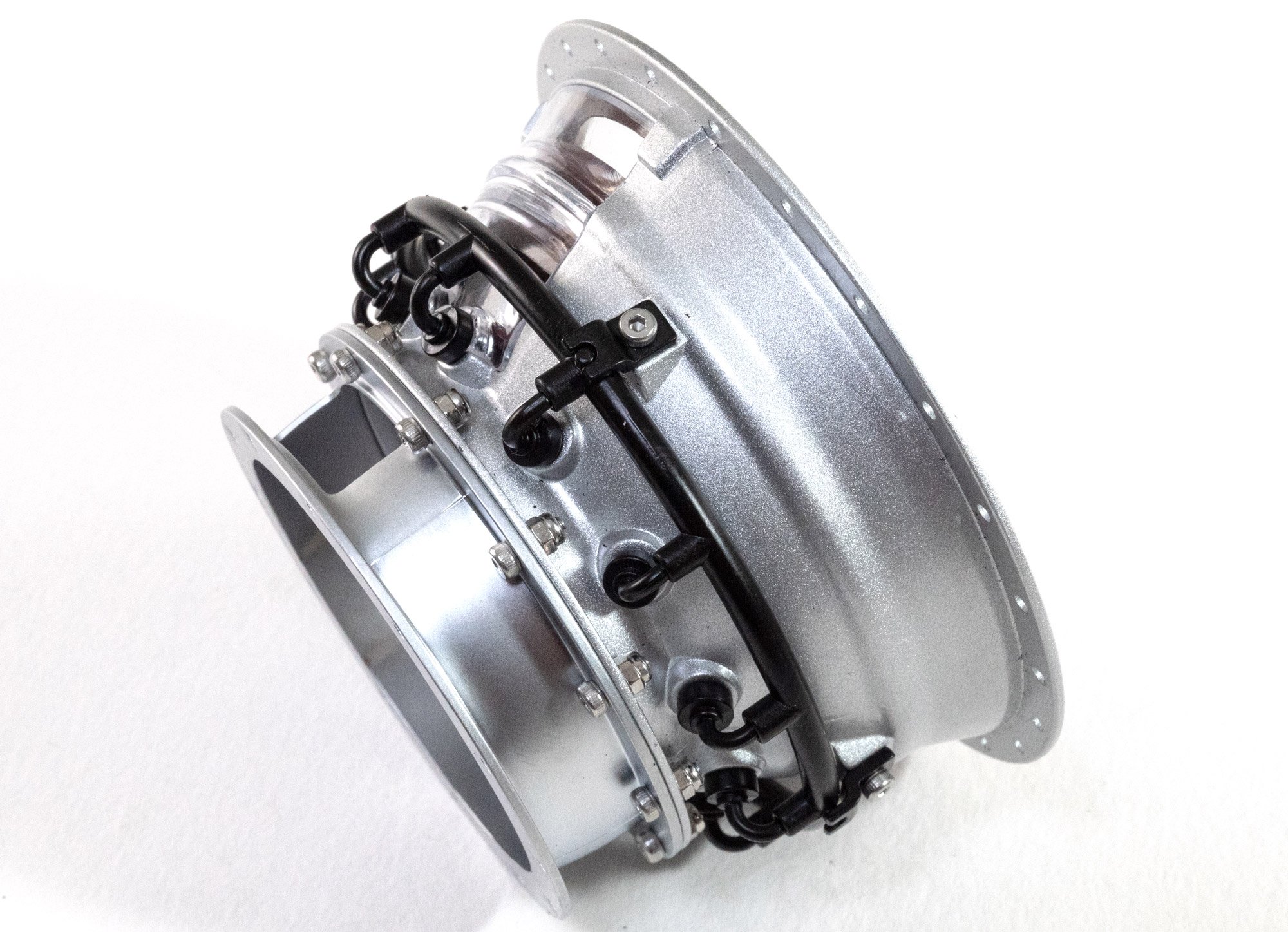
This unit is now fitted out with cooling pipes and their connection units. Extra clips are fitted over these which hold the pipes into the correct position to each other. The pipes are also numbered so you get them in the correct sequence, starting with the largest diameter ones. As with much of this engine, this assembly is quite heavy.

....to be continued.
-
Work begins!
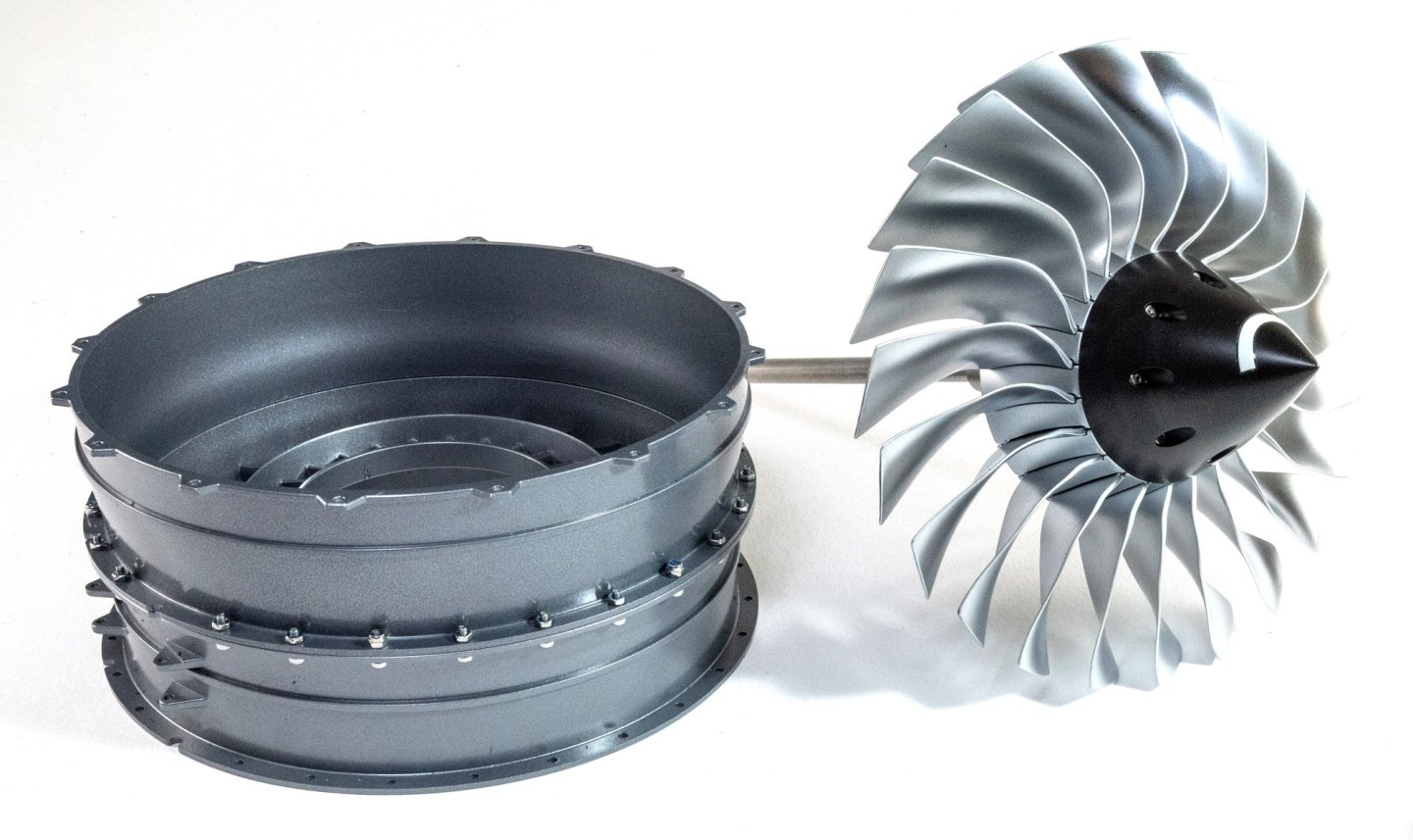
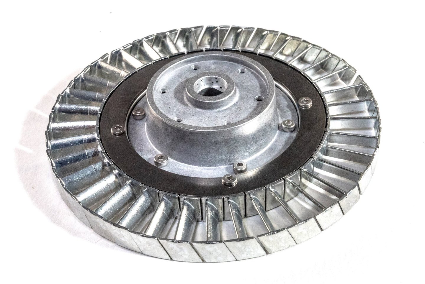
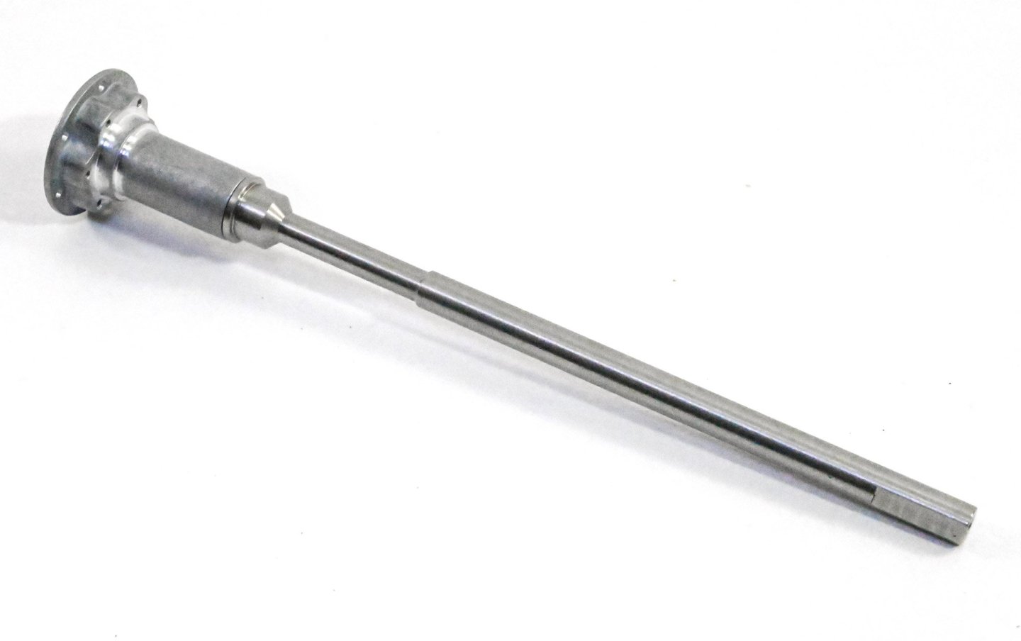
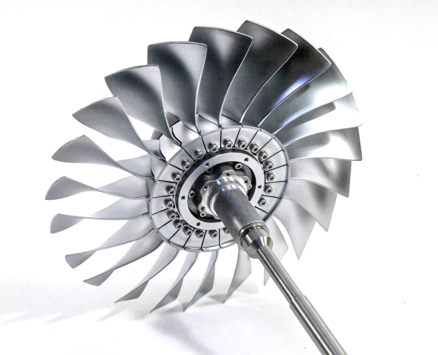
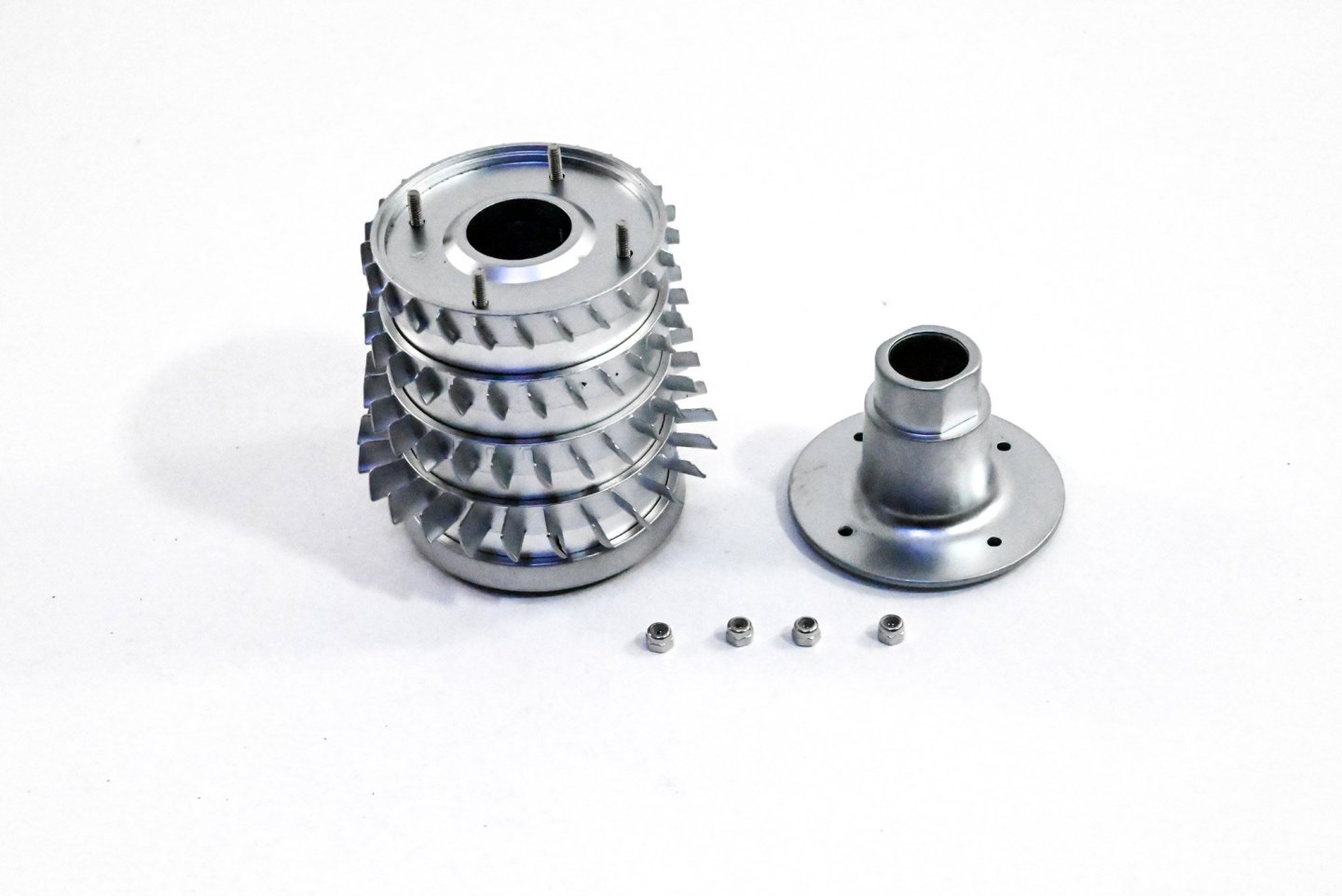
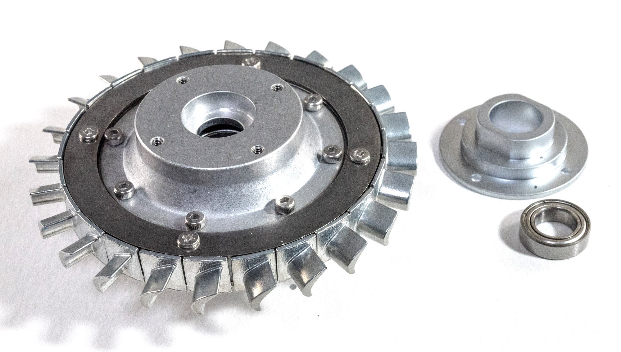
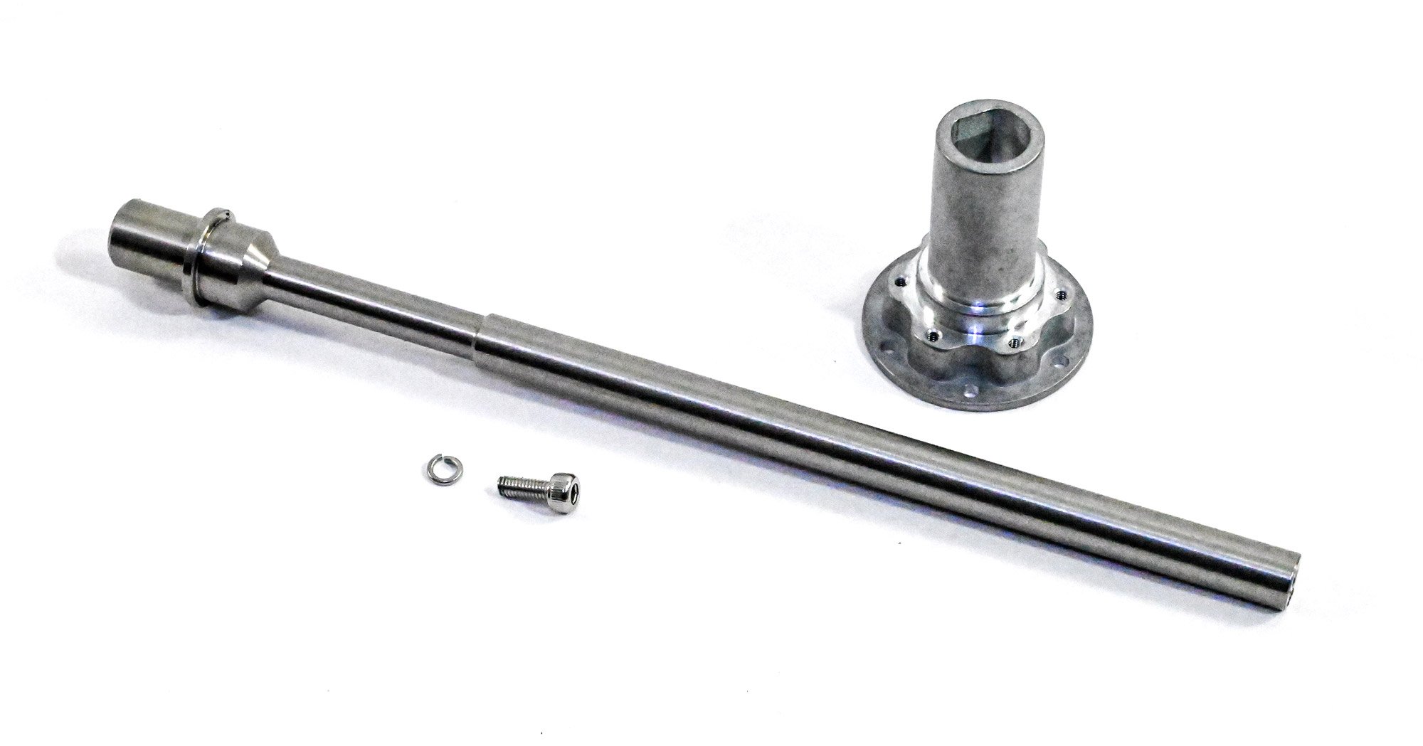
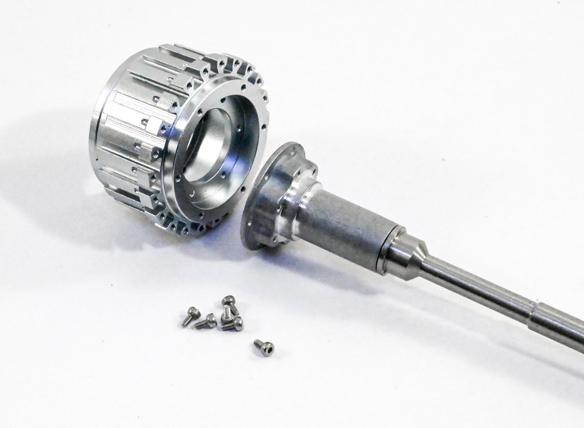
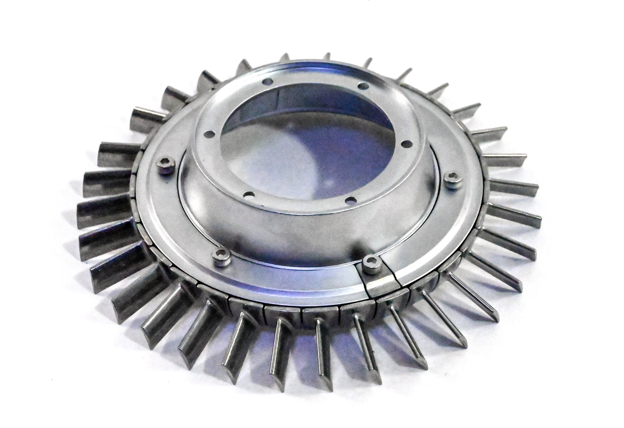
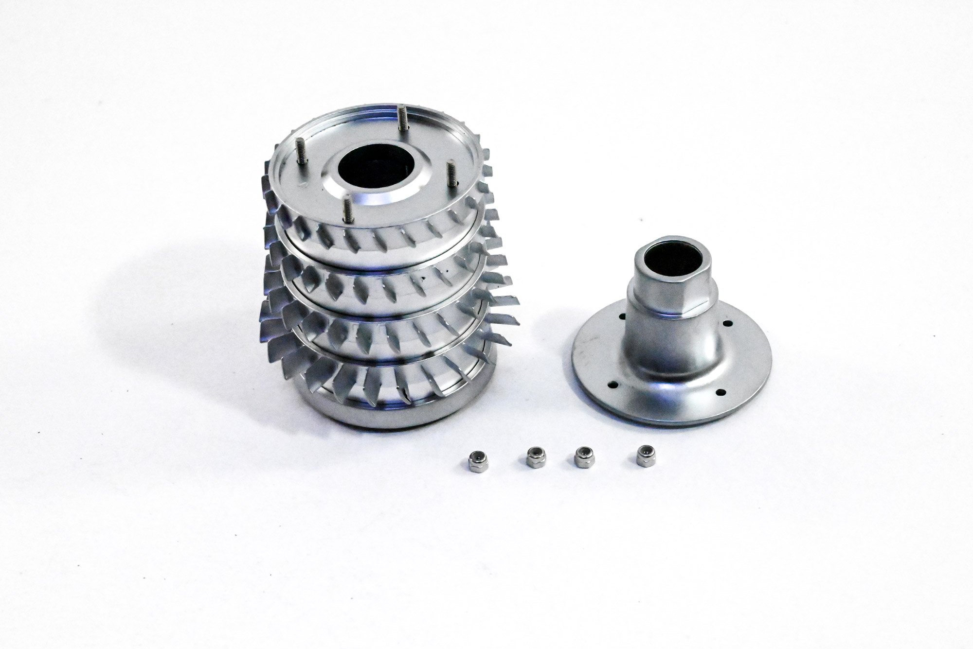
Fan and main shaft
We are immediately thrown into the main event on this kit, namely the engine's driveshaft and the intake fan (first low pressure rotor). The driveshaft is first bolted to the fan drum. Whilst you see a lock washer here, I have used thread-lock throughout this build to protect bolts from rotating parts, coming adrift, and also static bolts which could be affected by vibration. Oil bearings are lightly oiled and modelling grease compound has been added where appropriate.


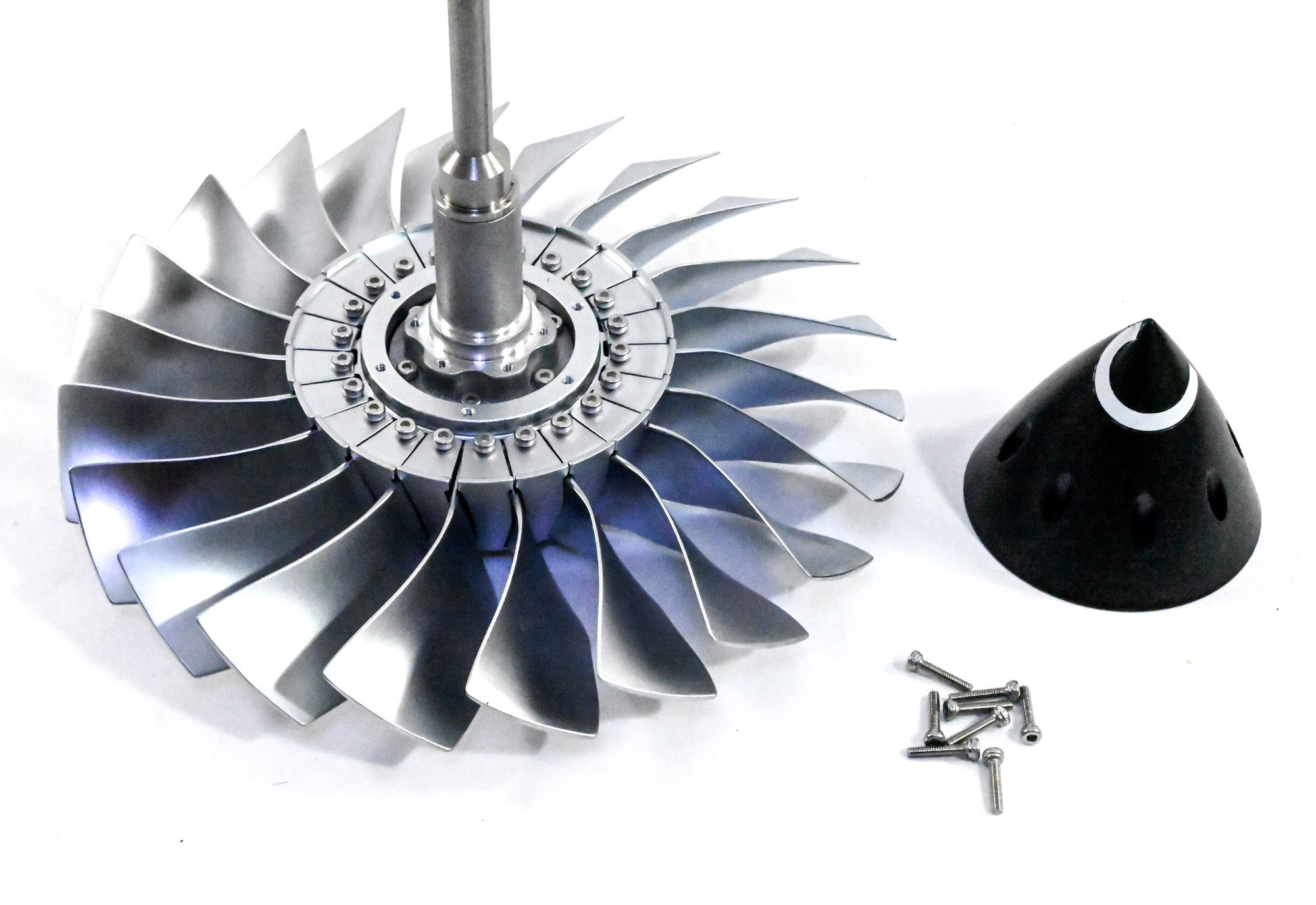
All of the fan blades are perfectly created so they are balanced. You'd have a real problem if the main fan was unbalanced. All of these blades are slotted into the drum. There is a little 'play' in these, as there is in the numerous other fans. This is perfectly normal.

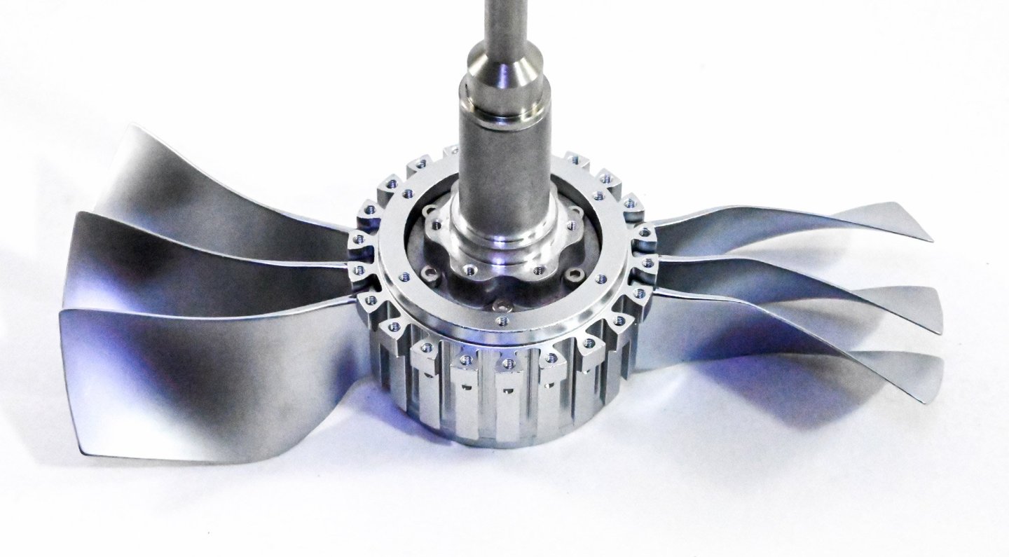
The blades are now fixed in situ with these fastenings which sit between the blades and are screwed from the rear of the fan drum.
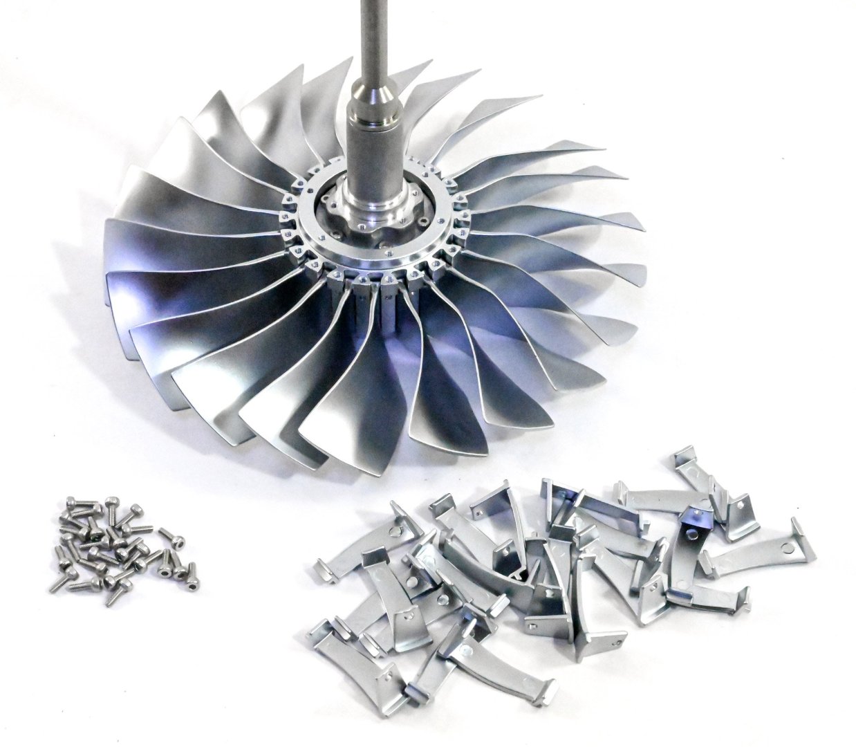
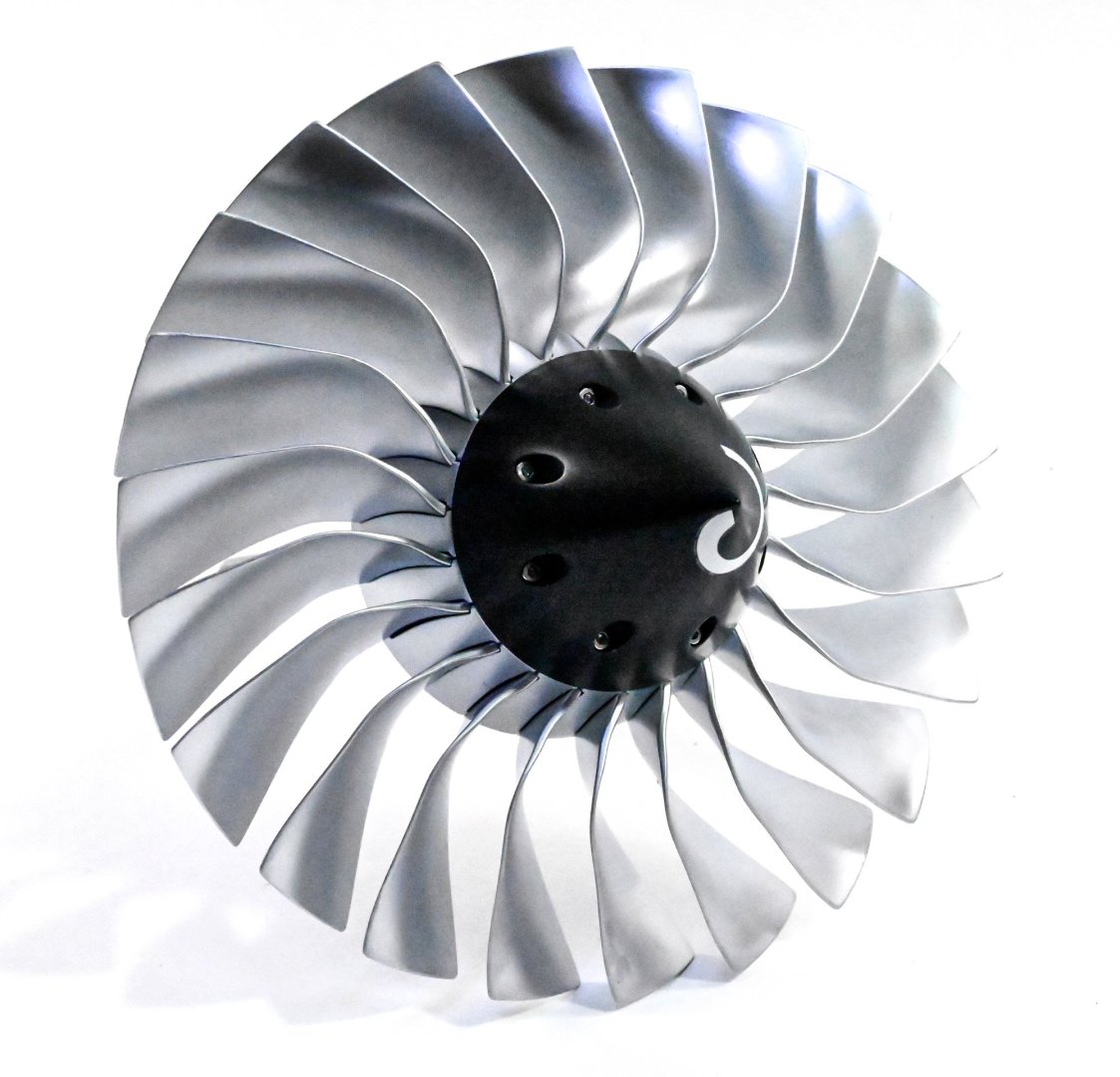
There is still a little unevenness in the position of the last parts, but this is entirely removed when the fan spinner is screwed into place. Note the spiral which is a safety feature of the real thing.

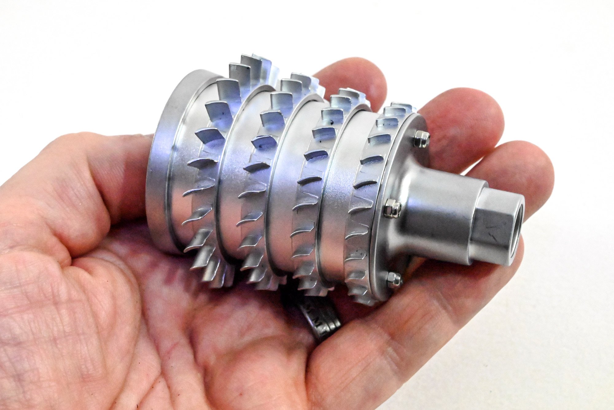
This is already a heavy and substantial subassembly. I put this to one side while I worked on the rest, making sure I didn't rest it on its fan blades.
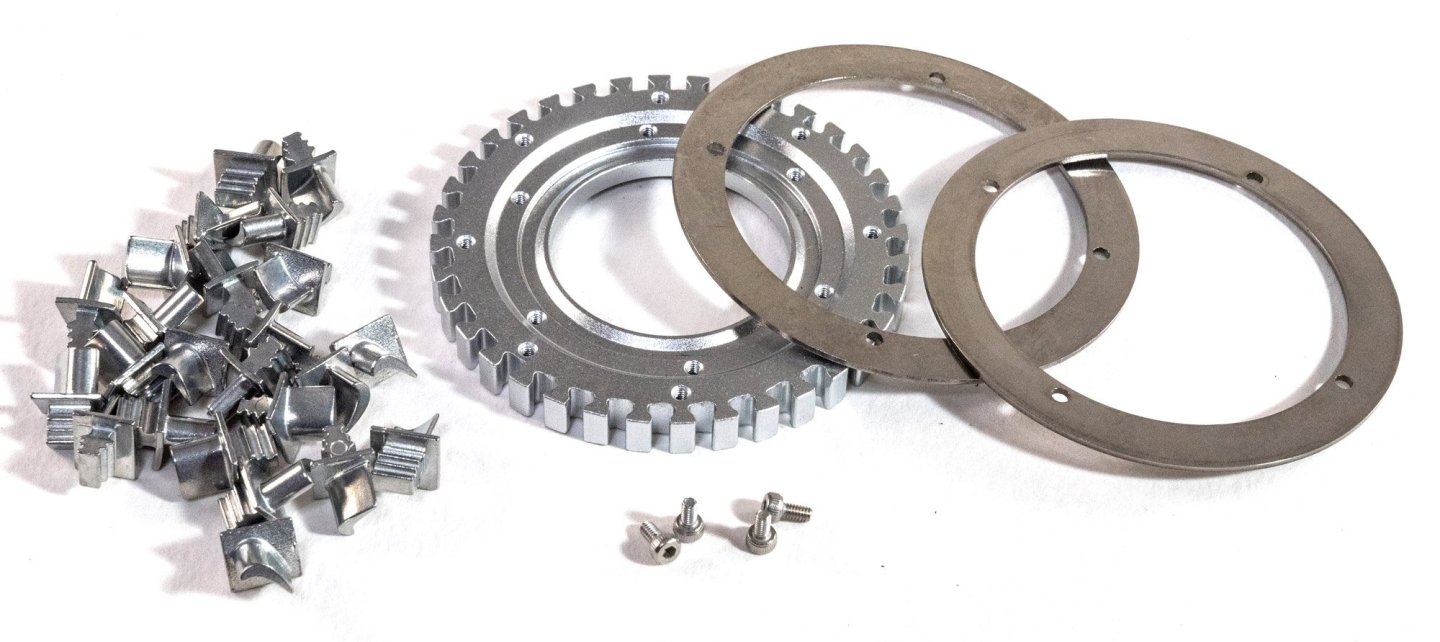
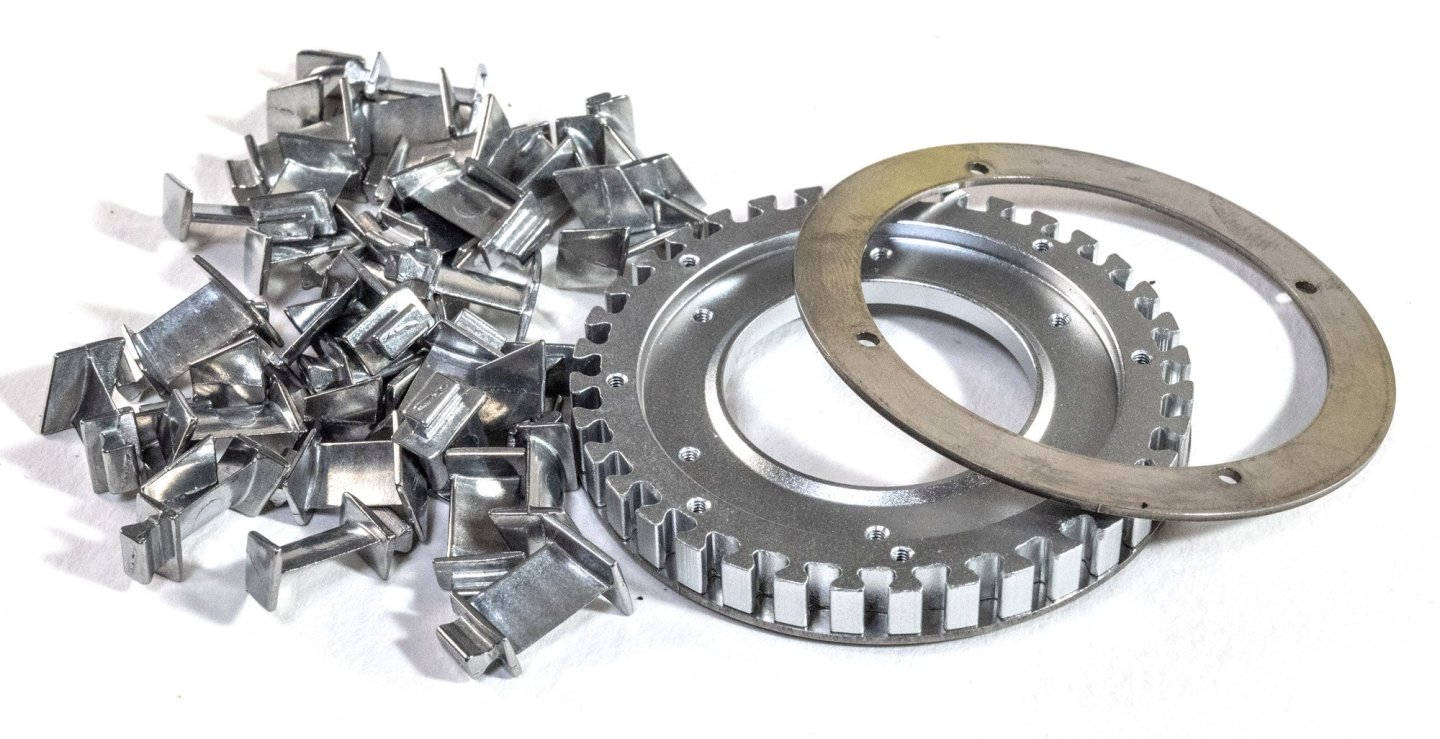
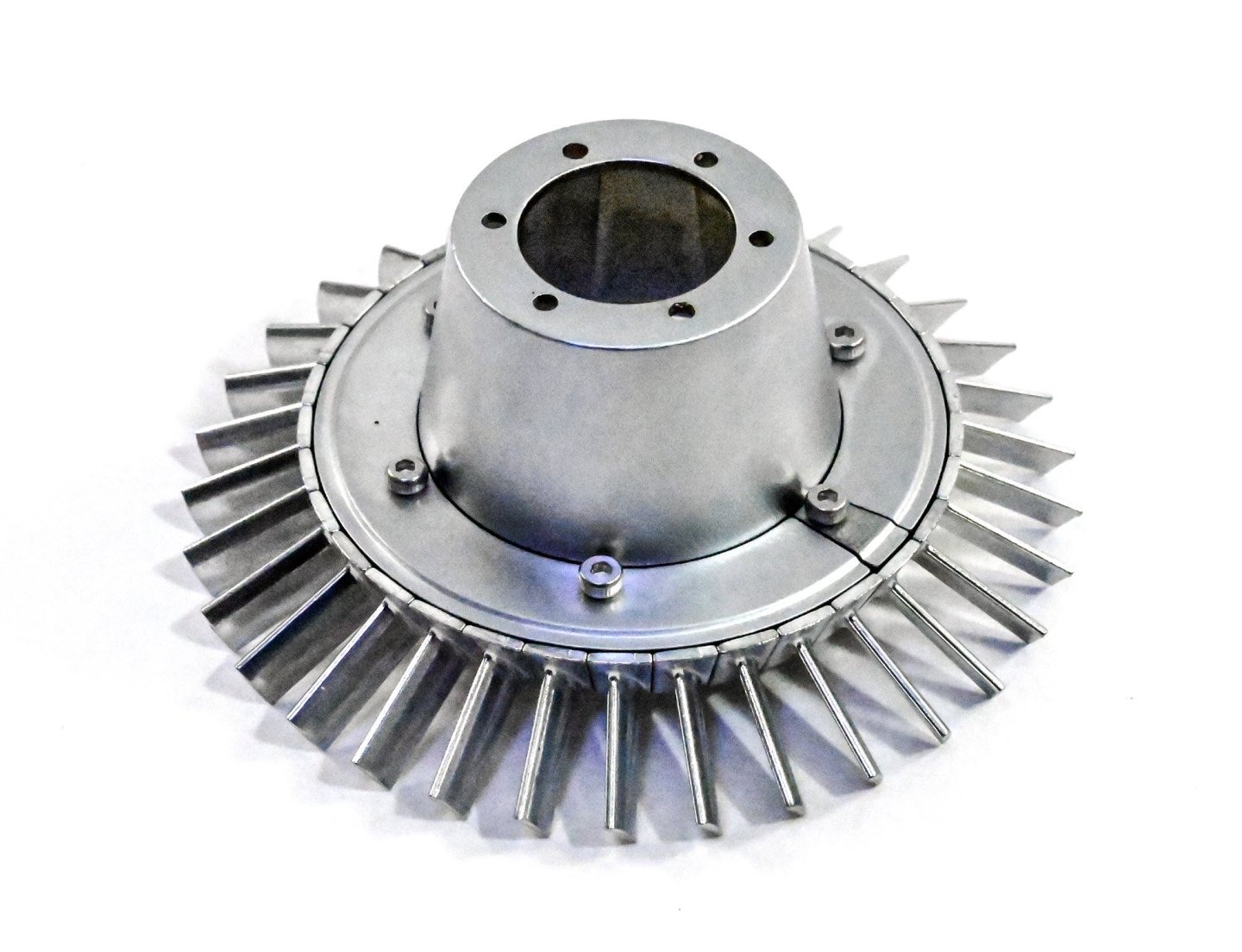
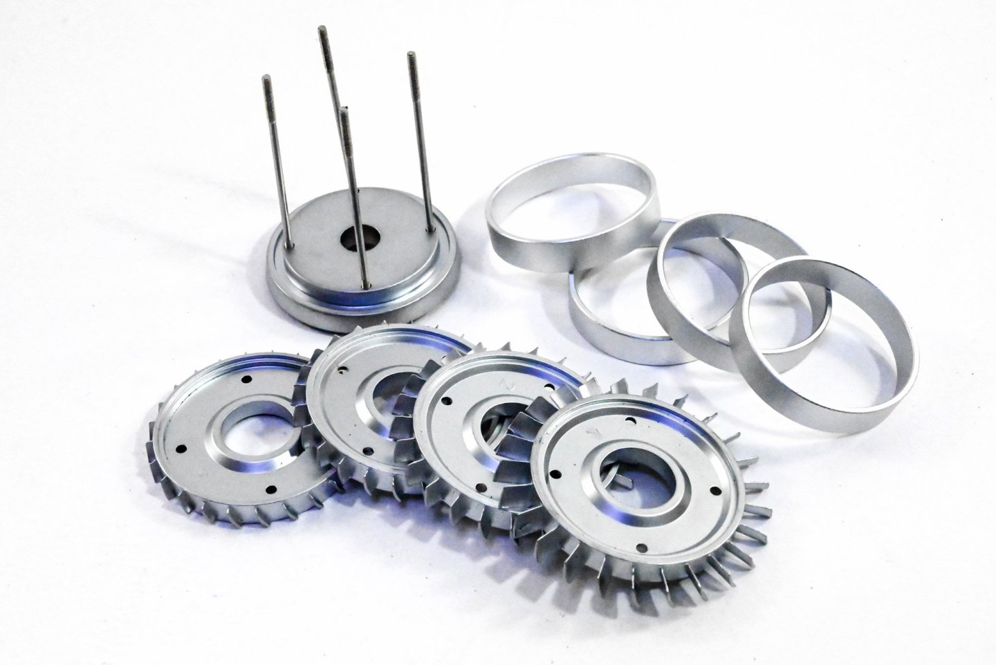
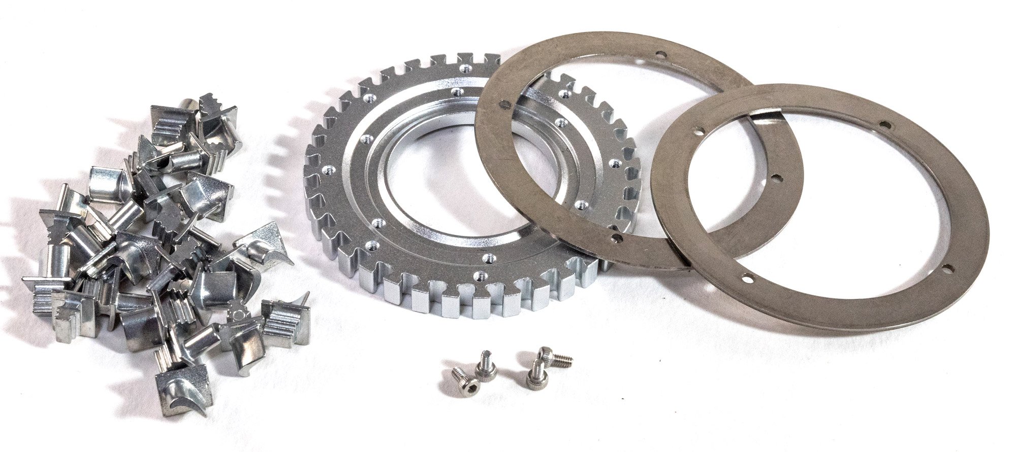
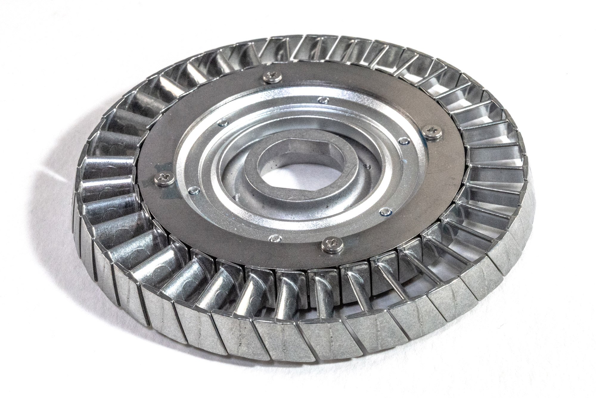
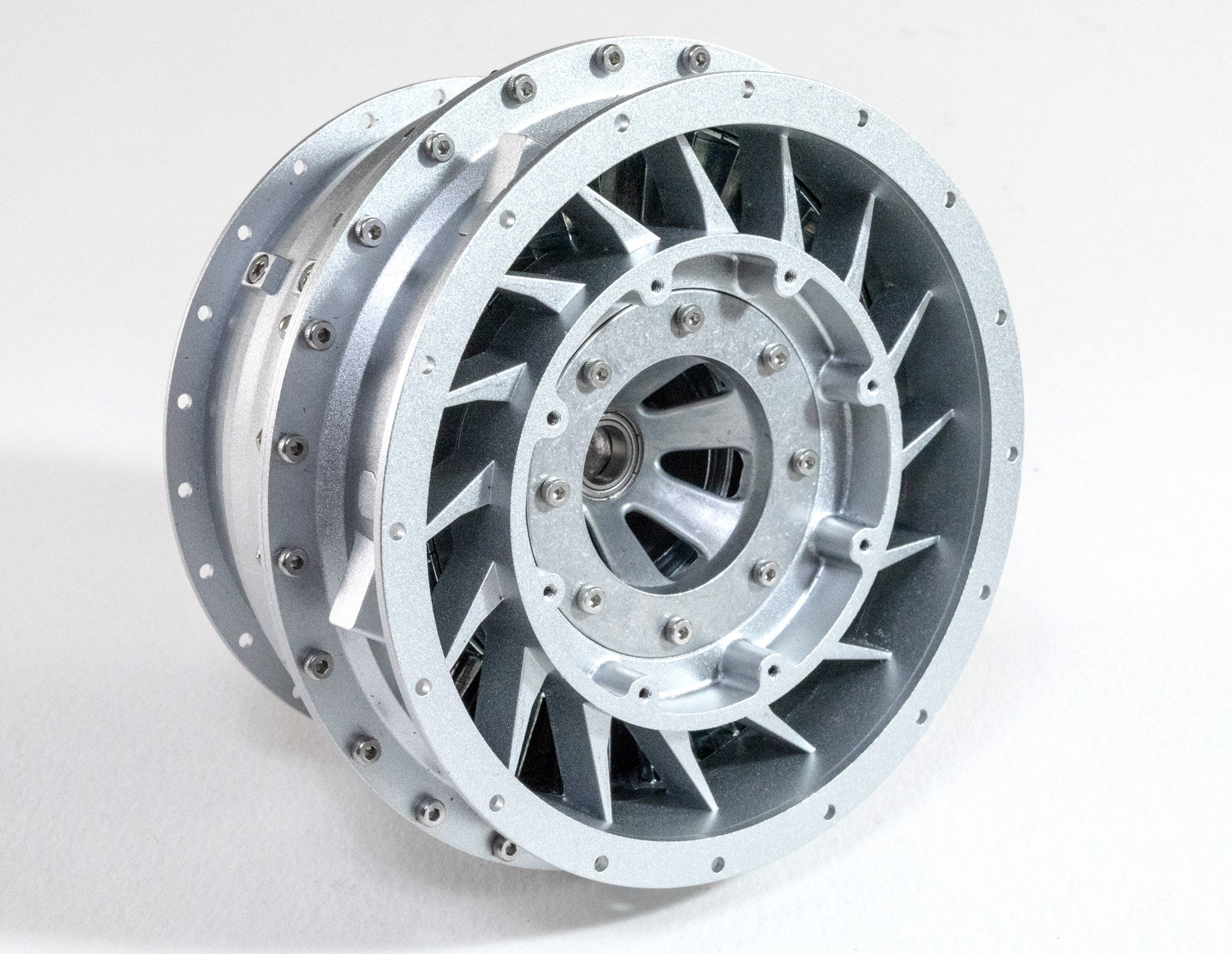
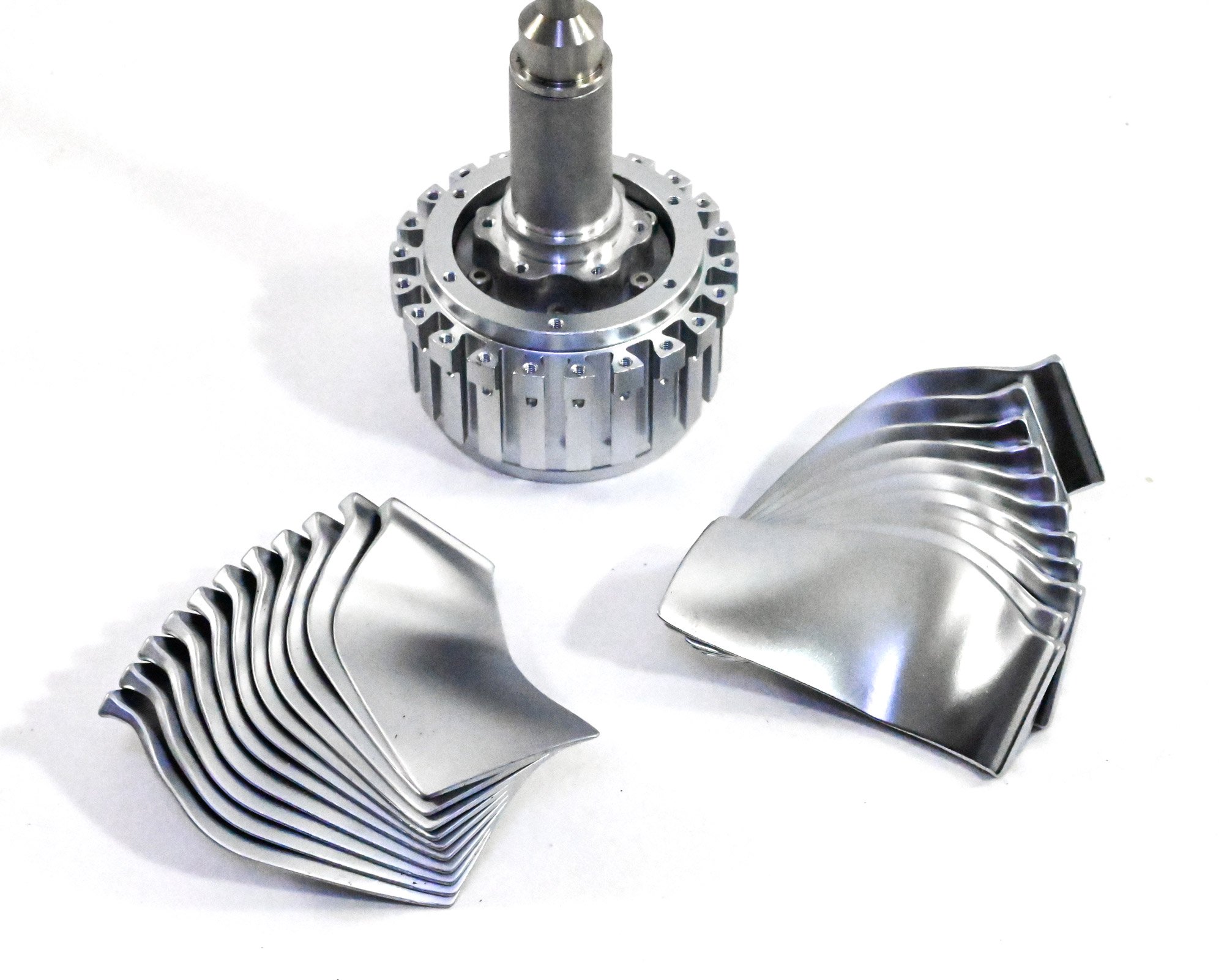
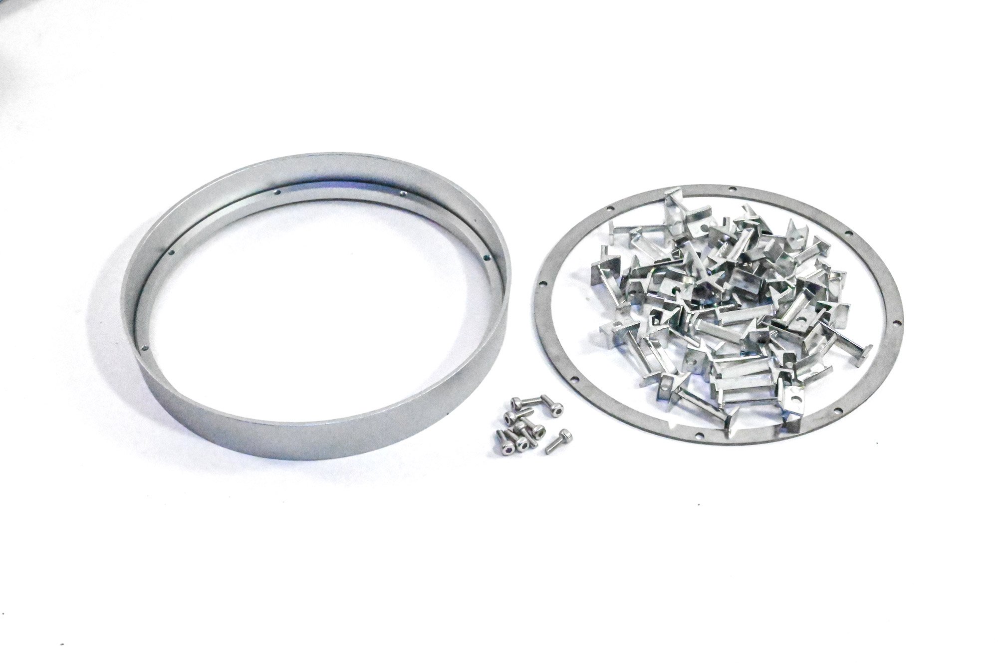
Second Low Pressure Rotor
We all know thatches engines have various high and low pressure rotors/compression, and this assembly is the rotor which will sit to the rear of the main fan. The parts to build this are seen here, with the separate blades. The two turntable parts are first bolted together and then the blades slotted between them in the correct orientation. Finally, a stopper is fitted to complete the turntable and prevent the blades from escaping.

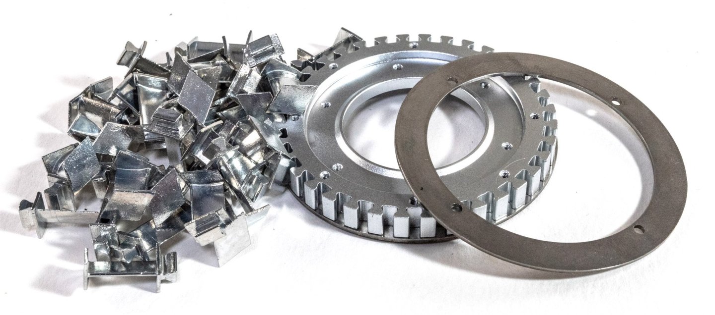
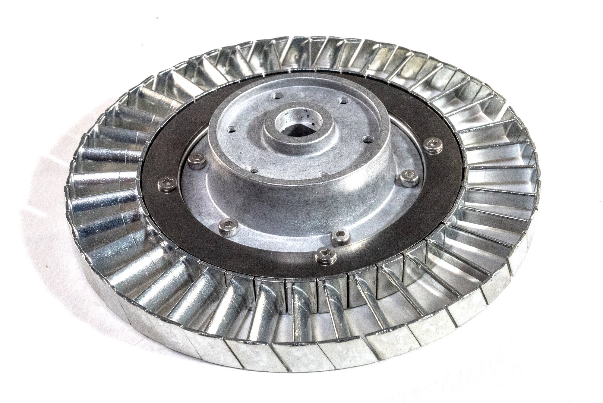
Second stage low pressure rotor
This assembly is built in exactly the same way as the one above. The only difference being the blade angles and the turntable drum shapes.
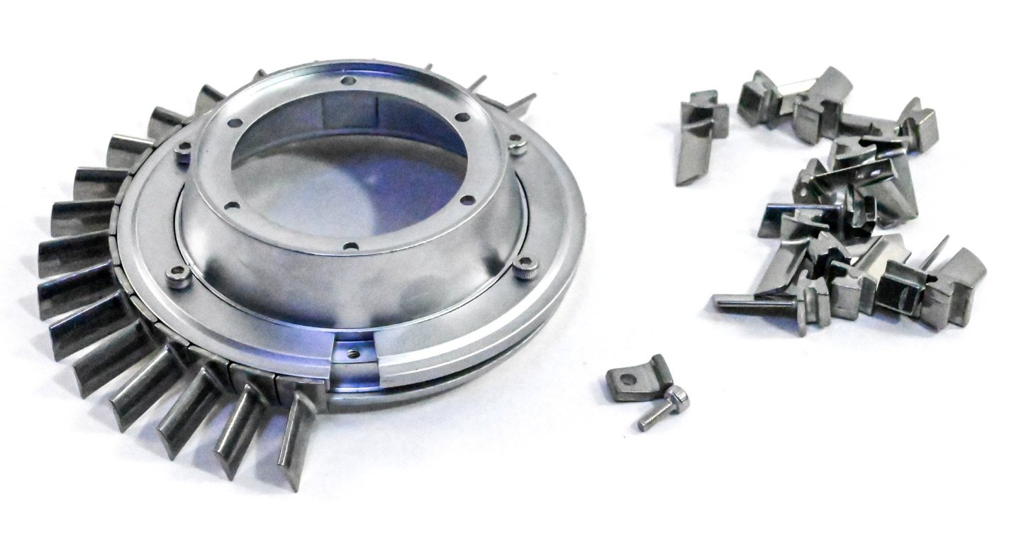
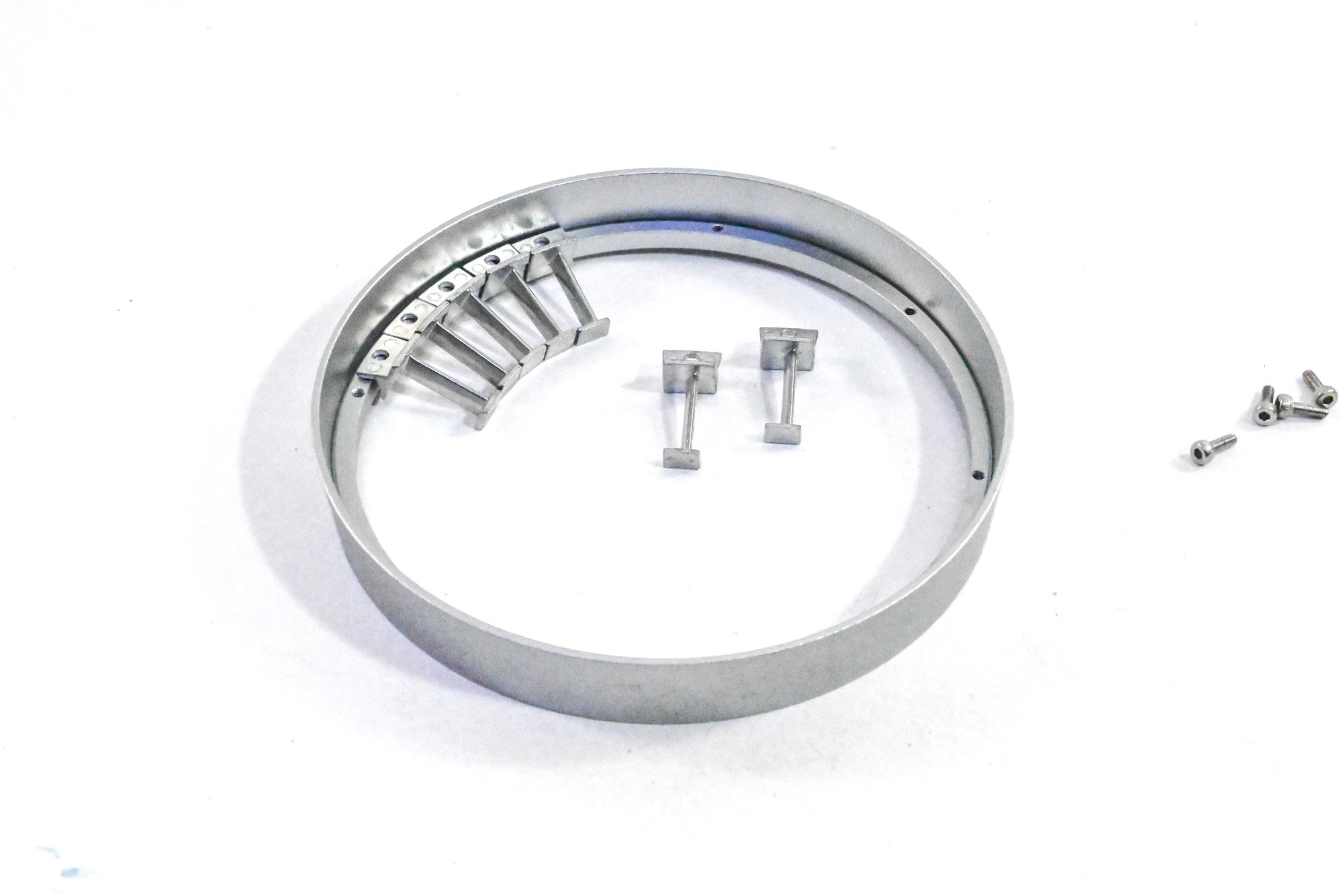
First low pressure stator
Whereas the previous assemblies were moving items, this one is static and will sit between the others. This consists of a static low voltage connector ring in which a set of stator blades are slotted into an internal recess in the ring. These seem a little loose until the securing ring is tightened up onto the blades and they form a complete circle which droops from the ring. EngineDIY sent me a set of replacement parts for these as the original ones and their customer service was super fast. No complaints whatsoever.

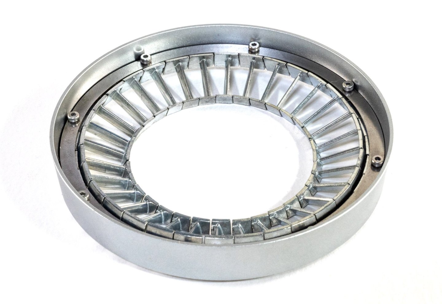
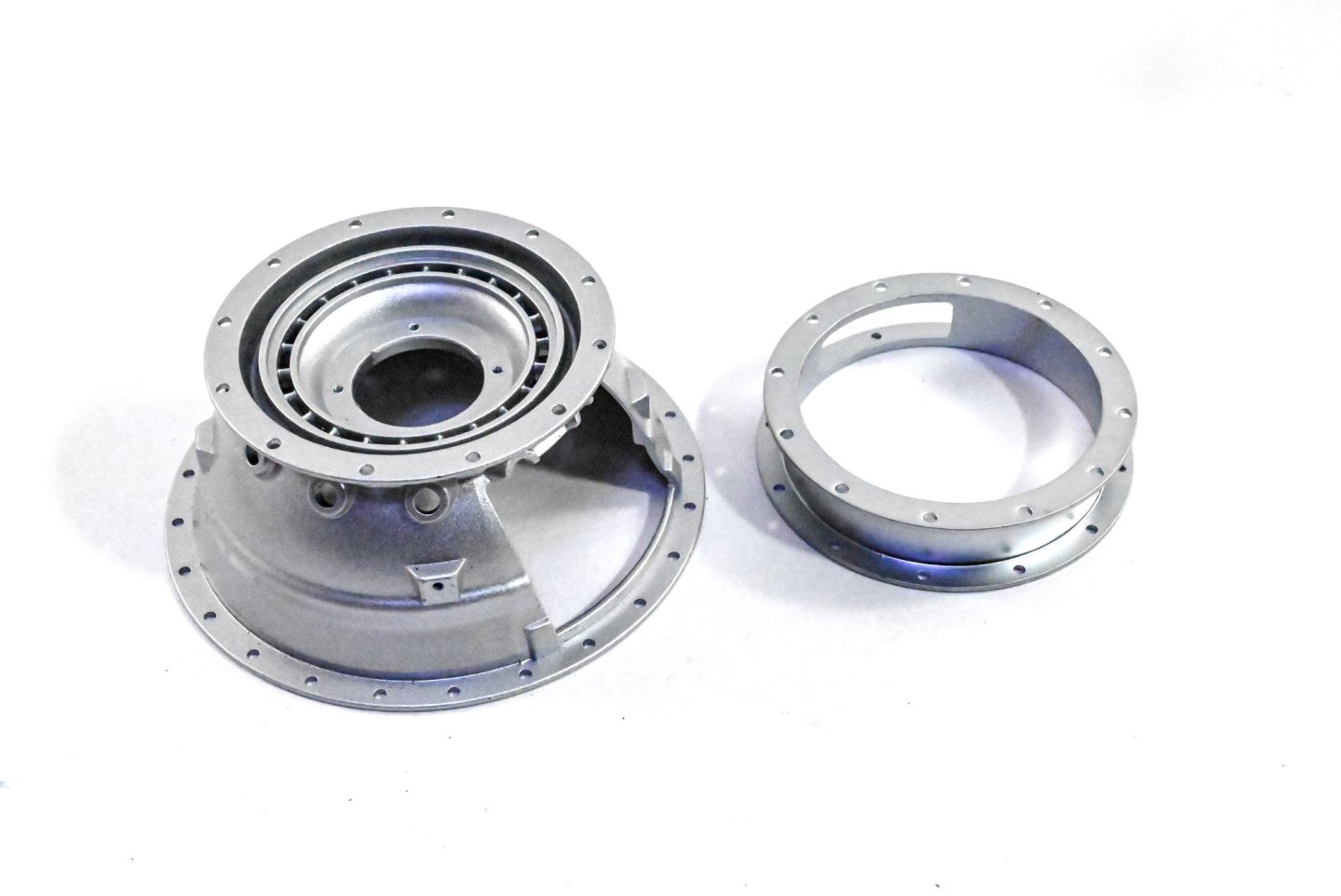
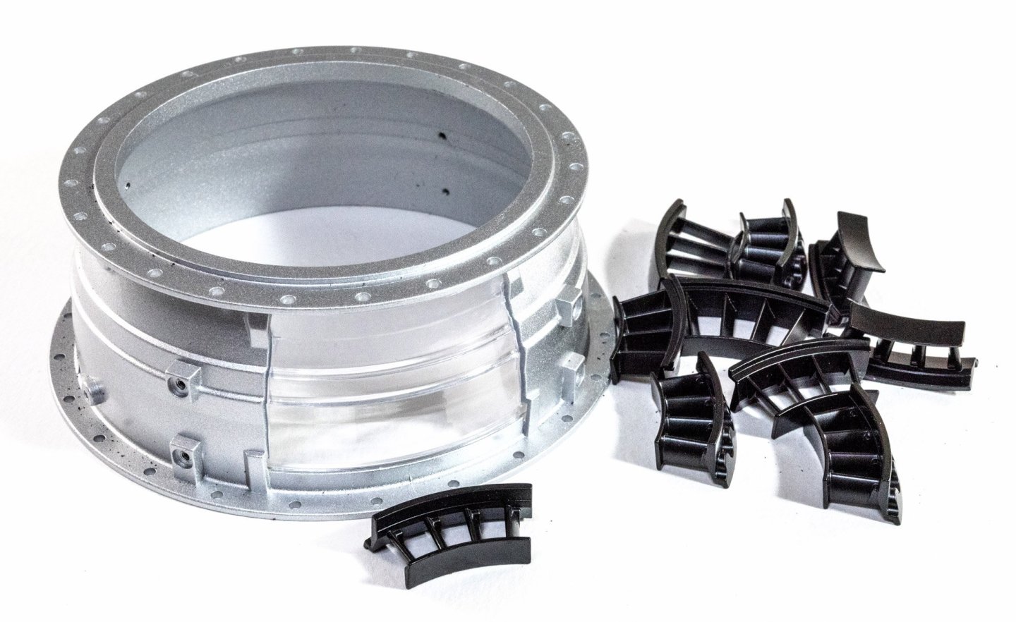
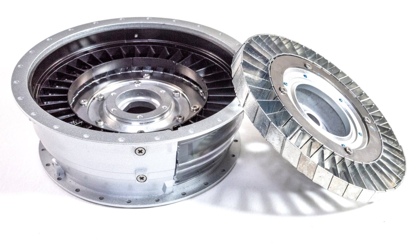
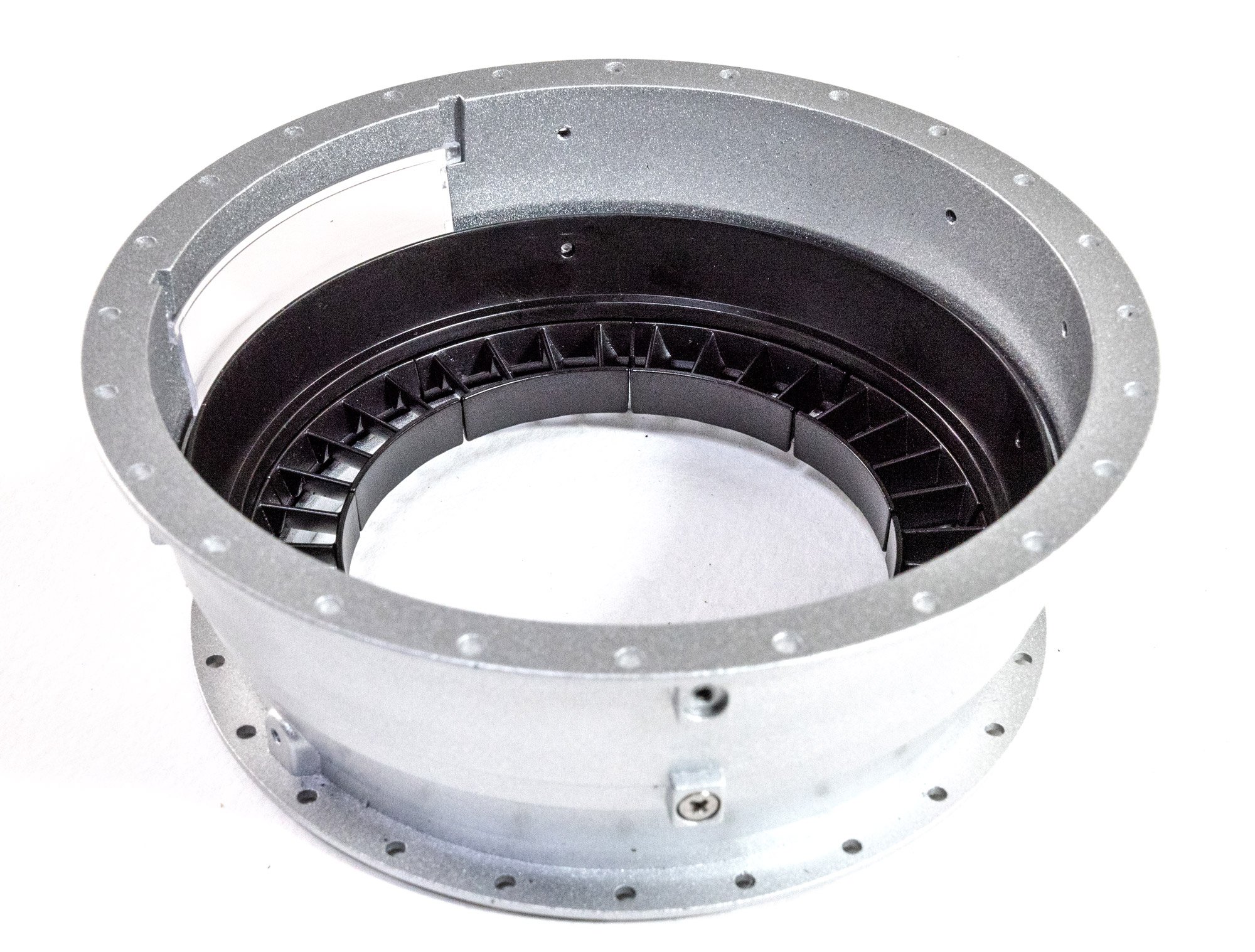
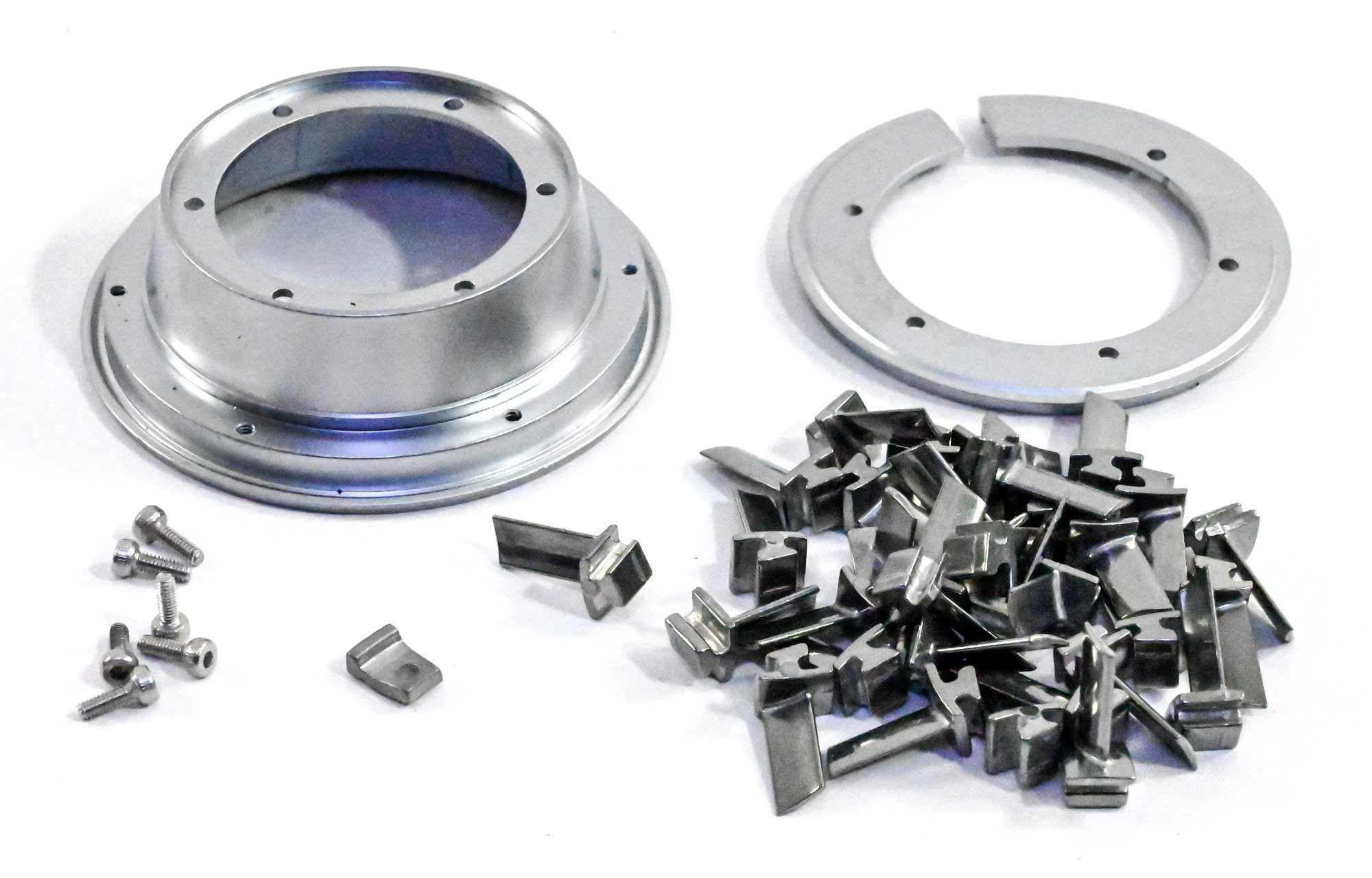
High Pressure Lower stator Case
We now turn attention to a part of the engine's outer case. This will sit just to the rear of the main fan casing and consists of two nicely machined halves into which clear viewing windows are inserted. Inside these sit two more rows of static stators, seen here in black. These are simply pushed into place and will move about, so it's a case of making sure they stay still until the halves are eventually bolted together.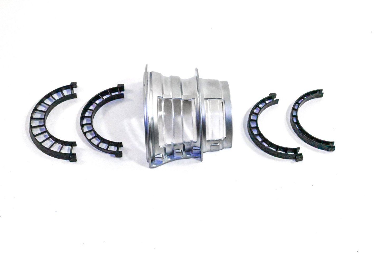
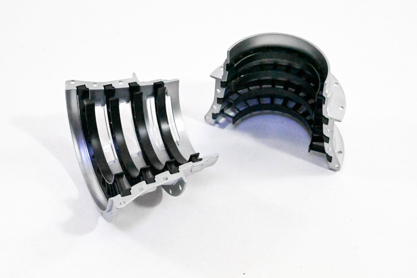
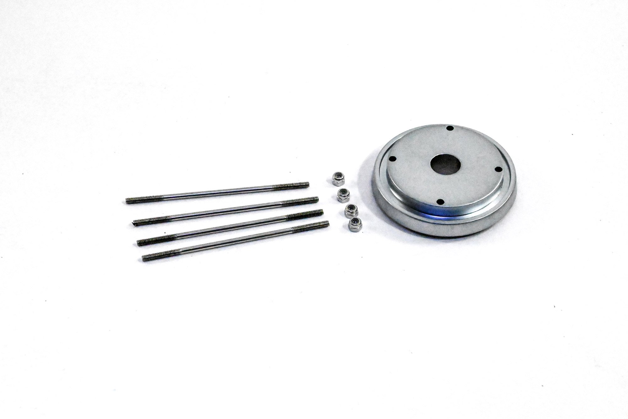
High Pressure Rotor
Inside that housing sits a high pressure rotor assembly. This is essentially a set of drums and rotors which are bolted together into a single unit. These are all slotted onto three rods which are then secured at each end of the drum.

....to be continued.
-
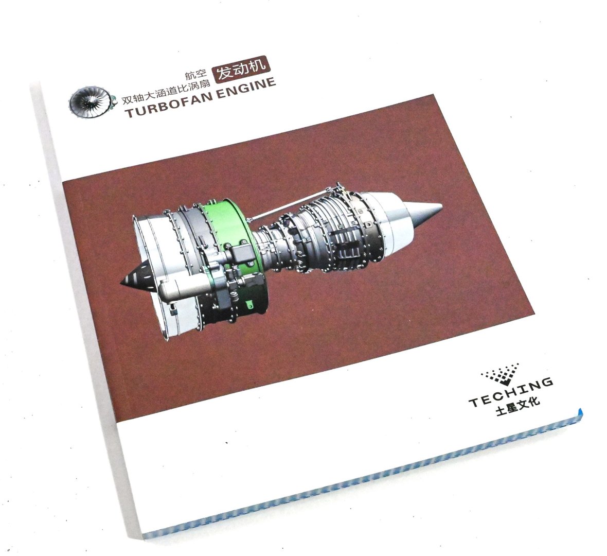
1:10 Turbofan Engine
Teching
Catalogue #33ED3479934
Available from EngineDIY for $999.99USD (minus discount)

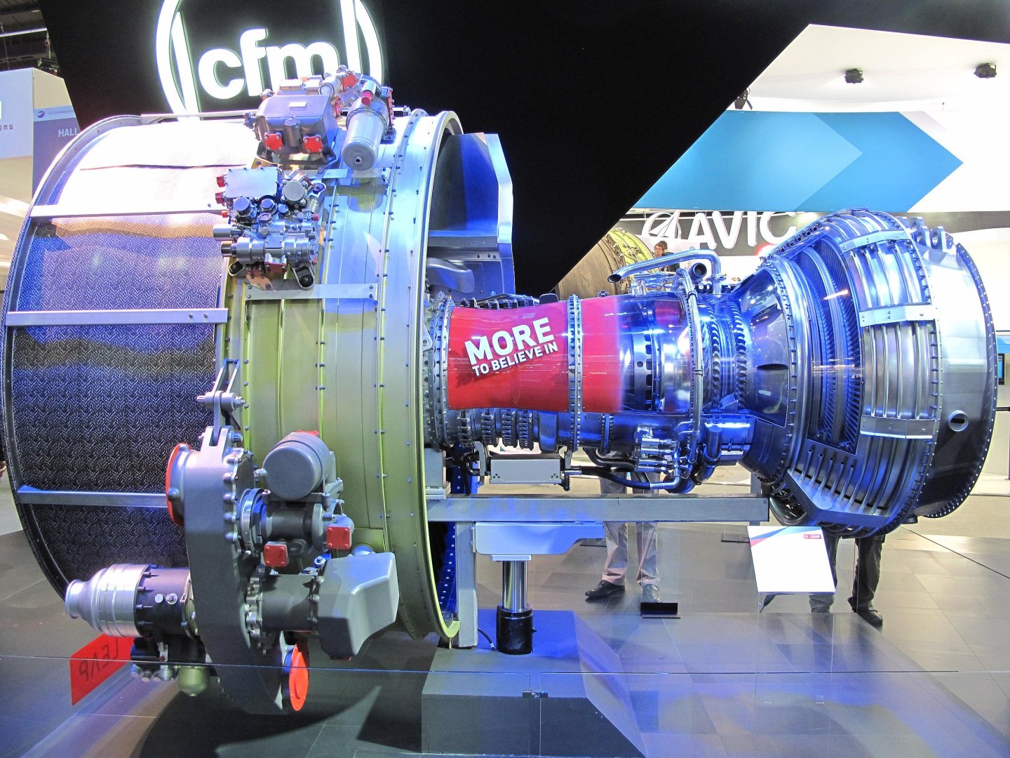
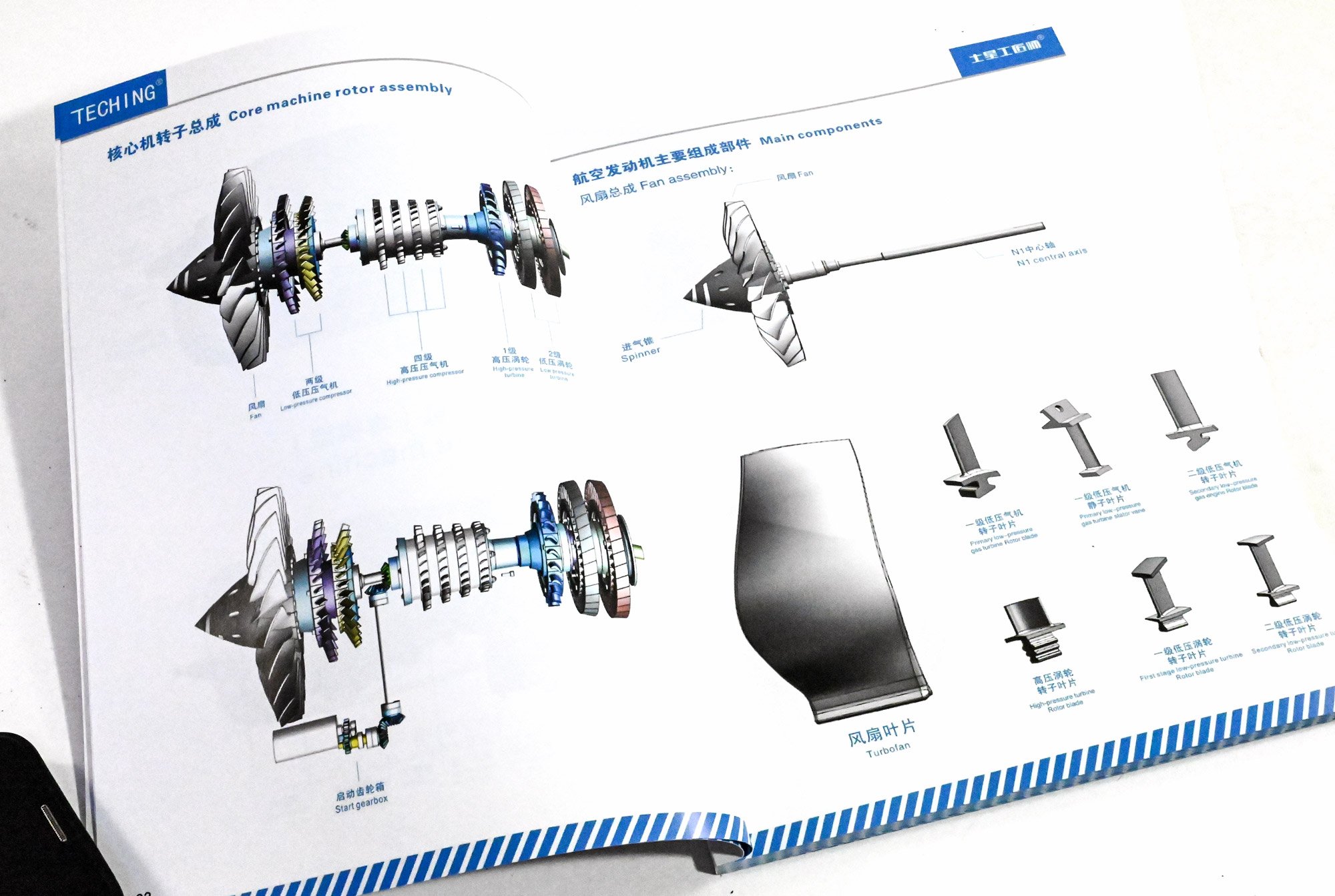
A turbofan or fanjet is a type of air-breathing jet engine that is widely used in aircraft propulsion. The word "turbofan" is a combination of the preceding generation engine technology of the turbojet, and a reference to the additional fan stage added. It consists of a gas turbine engine which achieves mechanical energy from combustion, and a ducted fan that uses the mechanical energy from the gas turbine to force air rearwards. Thus, whereas all the air taken in by a turbojet passes through the combustion chamber and turbines, in a turbofan some of that air bypasses these components. A turbofan thus can be thought of as a turbojet being used to drive a ducted fan, with both of these contributing to the thrust.

Animation of a 2-spool, high-bypass turbofan
A. Low-pressure spool
B. High-pressure spool
C. Stationary components
1. Nacelle
2. Fan
3. Low-pressure compressor
4. High-pressure compressor
5. Combustion chamber
6. High-pressure turbine
7. Low-pressure turbine
8. Core nozzle
9. Fan nozzle
The turbofan was invented to improve the fuel consumption of the turbojet. It achieves this by pushing more air, thus increasing the mass and lowering the speed of the propelling jet compared to that of the turbojet. This is done mechanically by adding a ducted fan rather than using viscous forces by adding an ejector, as first envisaged by Whittle.
(Information abridged from Wikipedia)
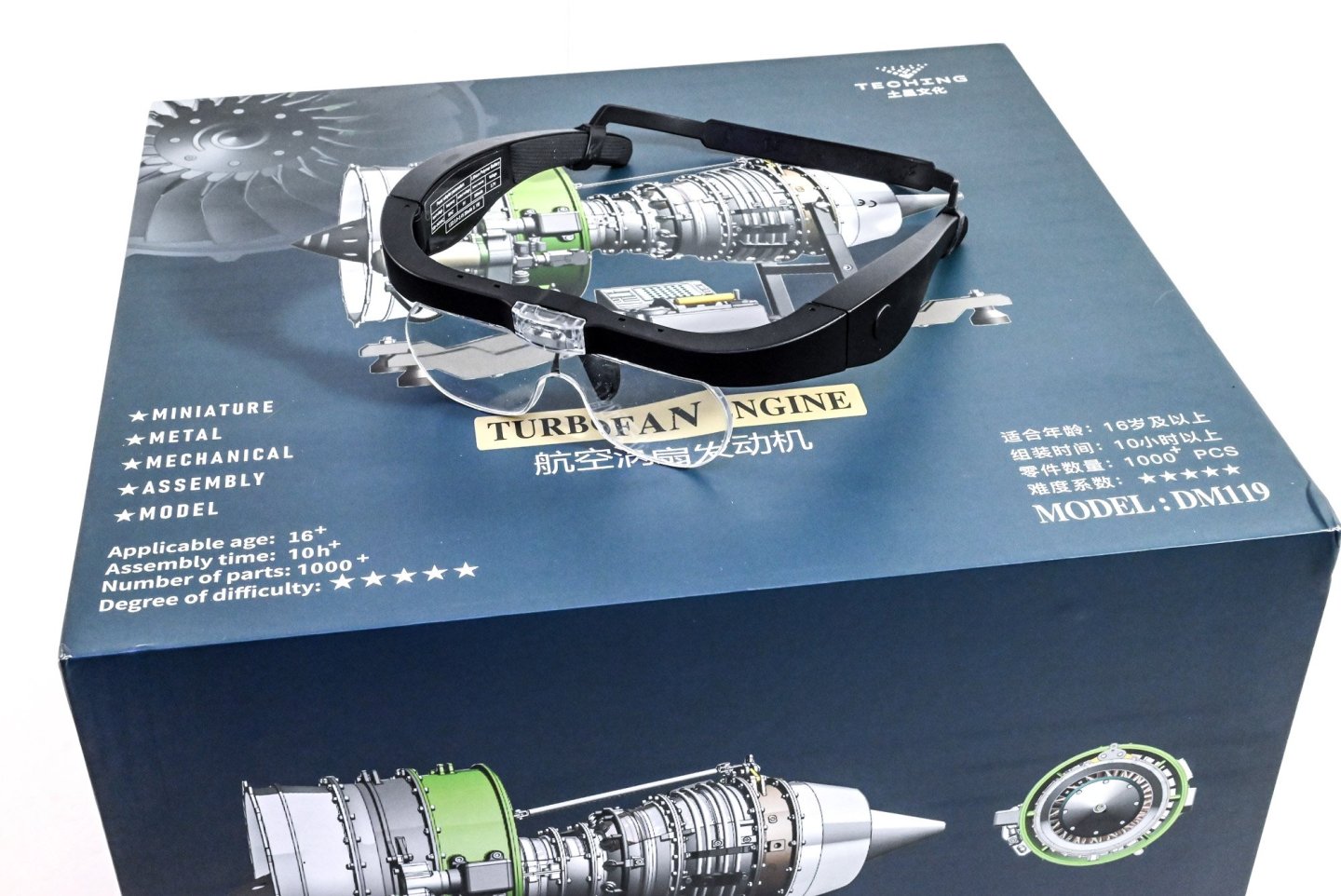
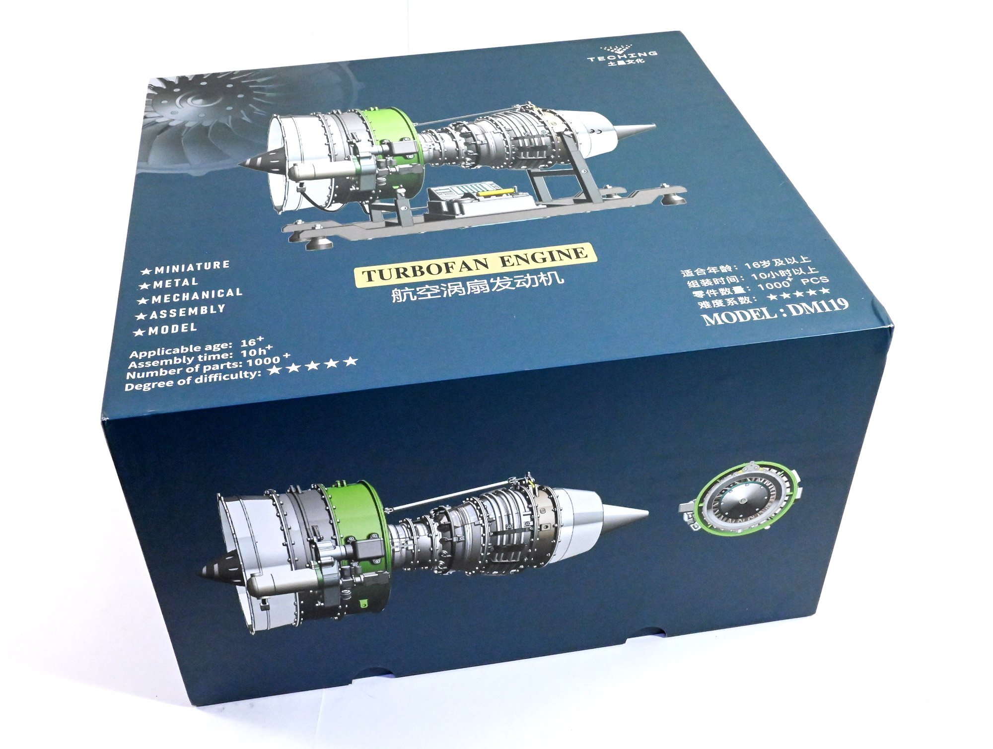
The kit
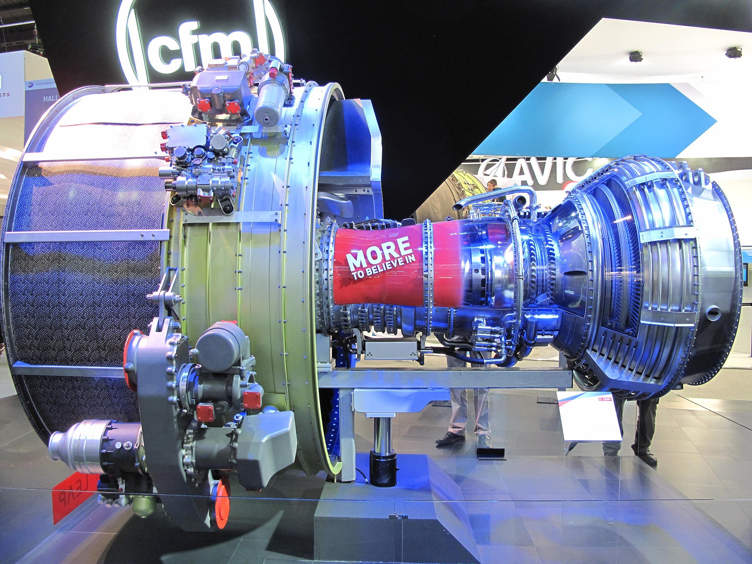
This is a large and heavy kit. It's also very expensive and I make no secret of this. The box with contents, weighs in at about 5kg, and the completed model at around 4kg. In all, there's over 1000 parts, including the various fittings of course. That product box is extremely sturdy and takes a real effort to get that lid from the base. You can get an idea of the size of this kit with my magnifying visor sat on top. The engine seems to be based on the CFM International LEAP turbofan engine, as fitted to the Boeing 737 MAX and Airbus A320 Neo. The finished model also features a test stand and a throttle unit with full engine sound.
Here are a few more specs, supplied by Teching.
- Material: Aluminum alloy + Stainless Steel
- Model: Dual Rotor Turbofan Engine
- Scale: 1/10
- Model Length: 380mm
- Fan Diameter: 165mm
- Number of Parts: 1000+PCS (Components: 400+PCS, Screws & Nuts: 600+PCS)
- Drive System: Motor-driven
- Battery: 3.7V 800mAh Lithium Battery
- Power Charging Cable: DC 5V USB Cable
- Charging Time: 3 hours
- Battery Life: 1 hour (at Full Charge)
- Assembly Time: Approx. 10 hours
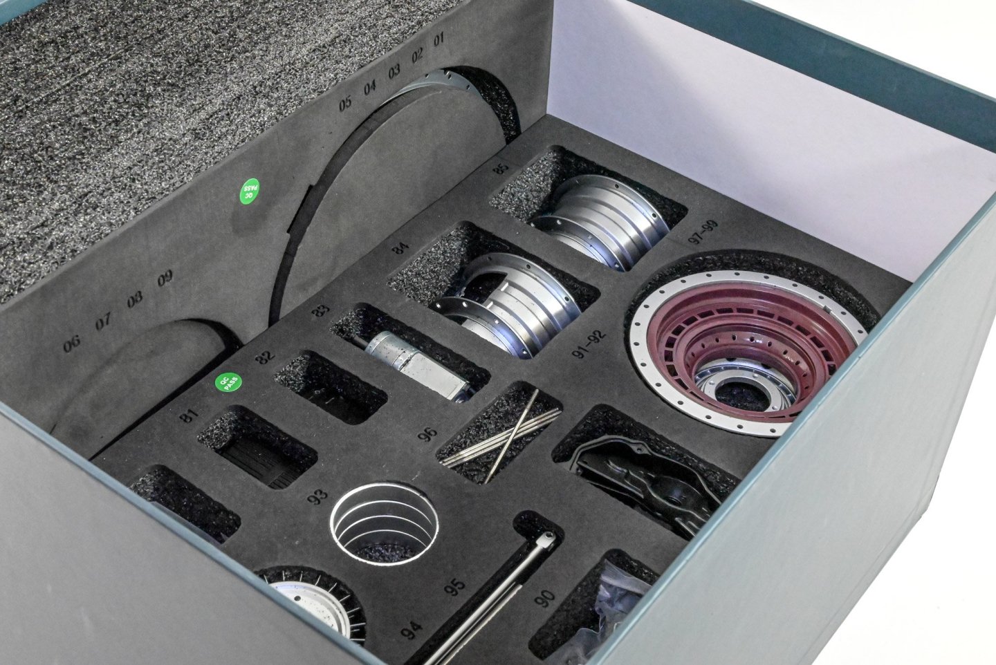
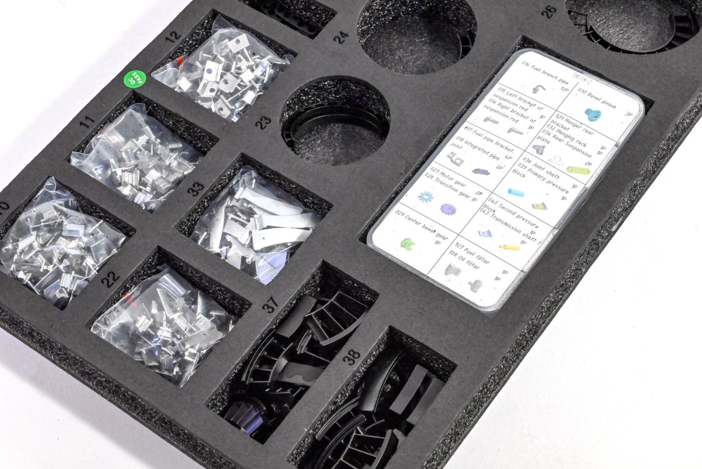
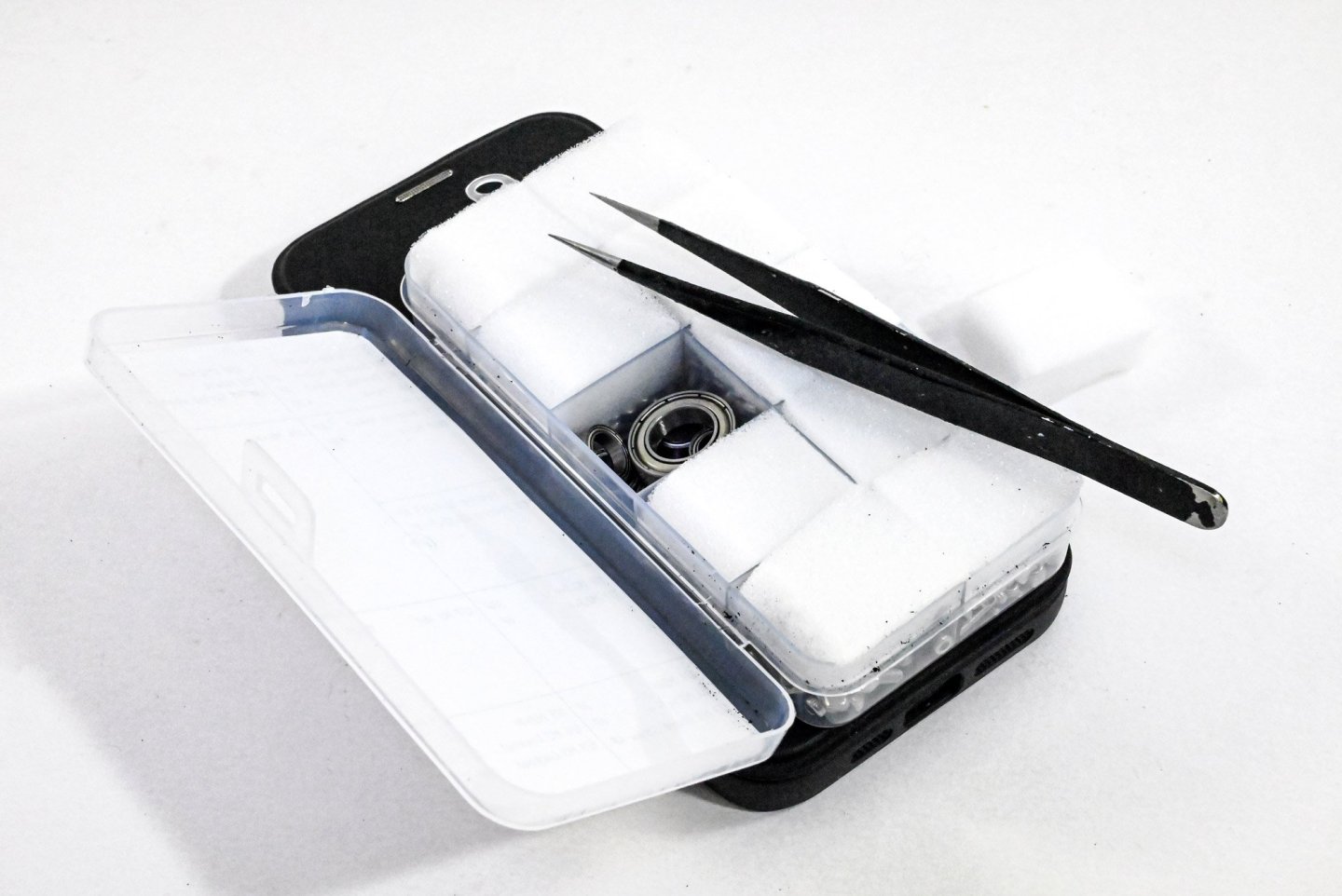
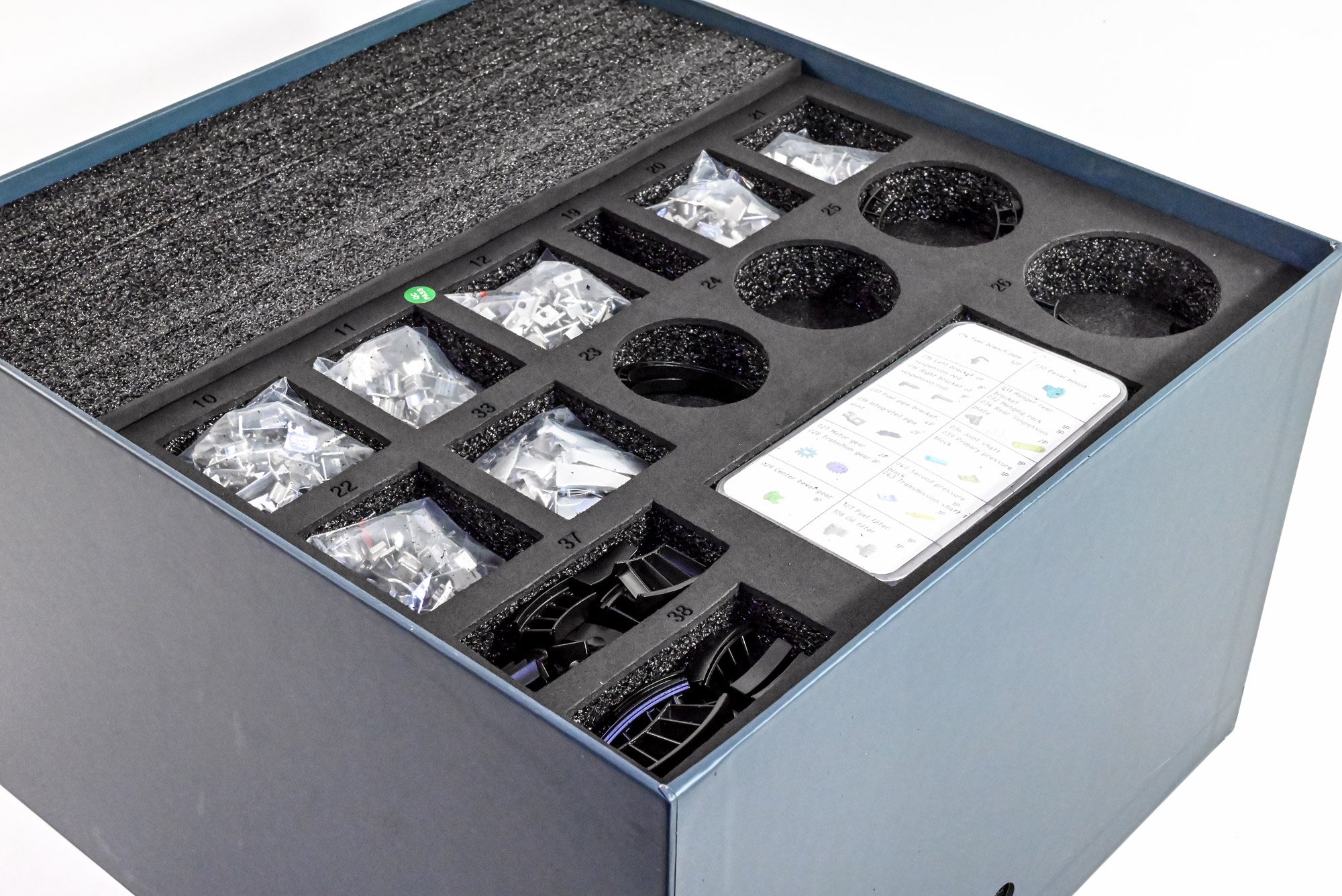
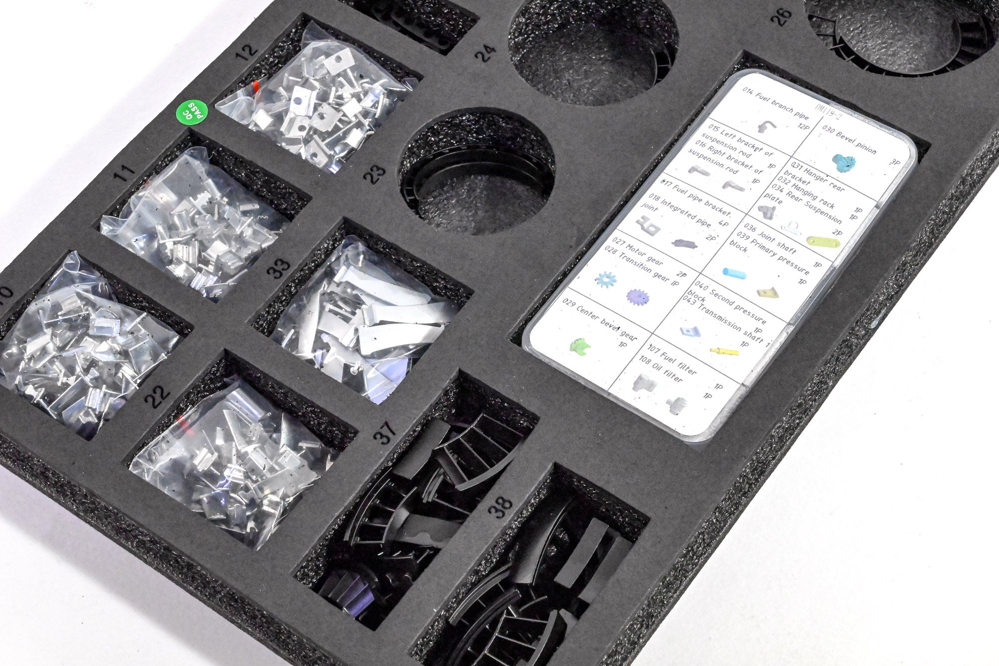
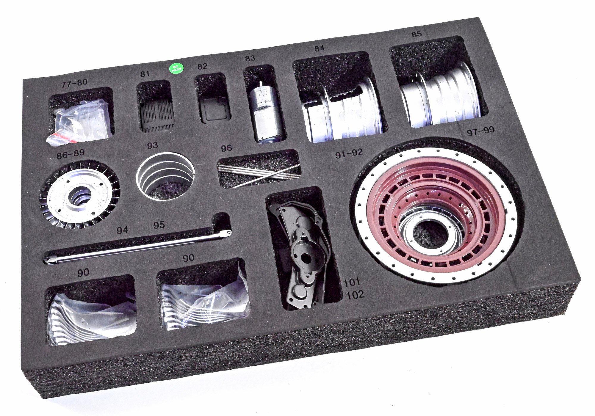
Underneath that heavy lid are several trays of parts, all numbered so you know exactly where to find the parts you need. A number of parts are fairly similar, so it's important you use the correct ones as you go. On top of the parts trays is a clear acetate sheet to make sure nothing comes loose, and lastly, the colour instruction manual is provided.

Here you can see just how those parts are supplied. Many smaller parts, such as stator blades etc. are packed into clear wallets and then sat within their numbered recesses. One point to note here is that there is a little fine, slightly powdery debris on many parts, from that foam. I found that blowing the parts with an aerosol cleaner helped first...especially as the construction is precision.
Tray 1

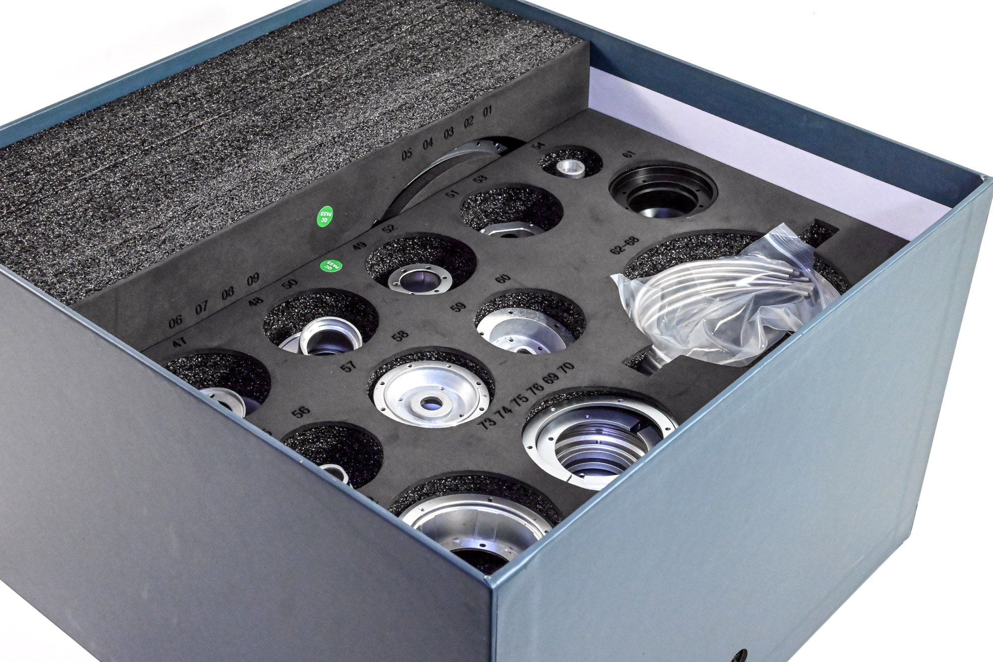
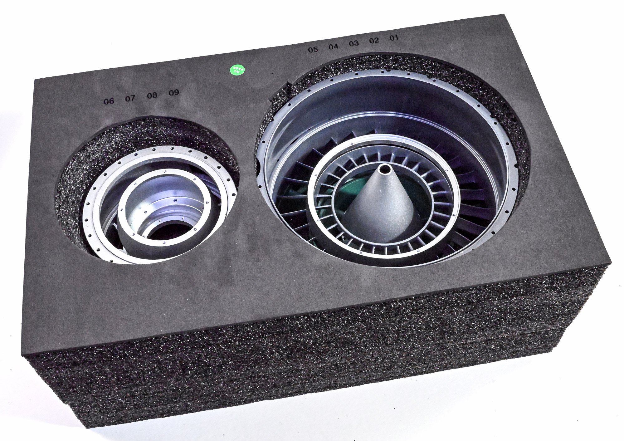
Tray 2

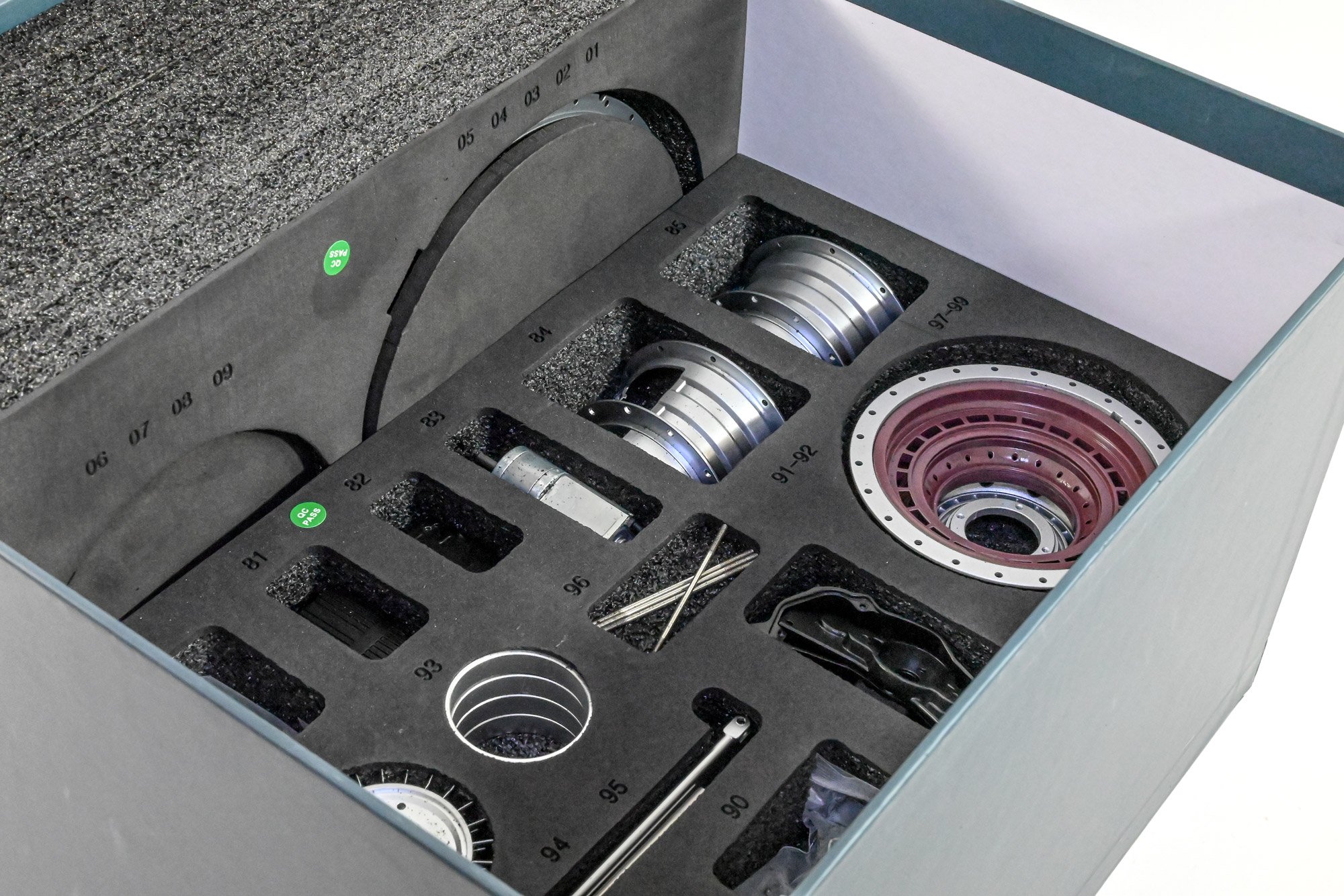
Tray 3
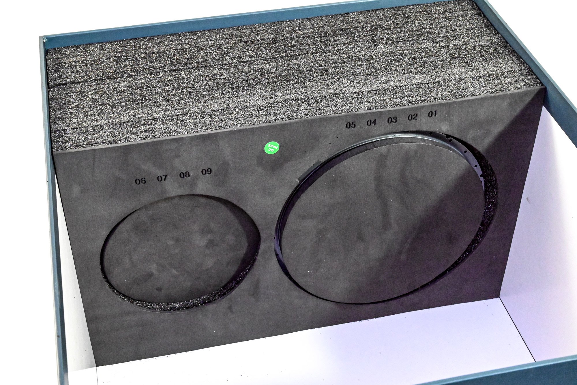
Tray 4

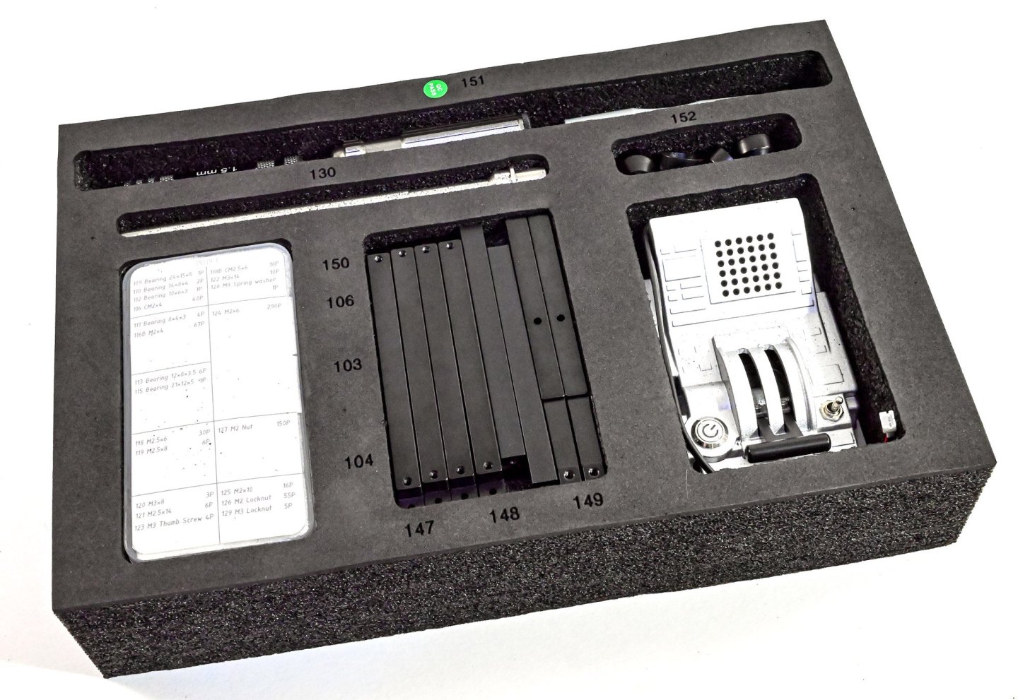
Tray 5

I've now laid out the trays so you can see the parts a little clearer. the main parts have either an anodised, dipped, or painted finish. All of the finishes are robust and not easily marked. All of the black parts you see are also metal. The only plastic parts I believe I encountered are the clear viewing windows for the various cutaway sections.
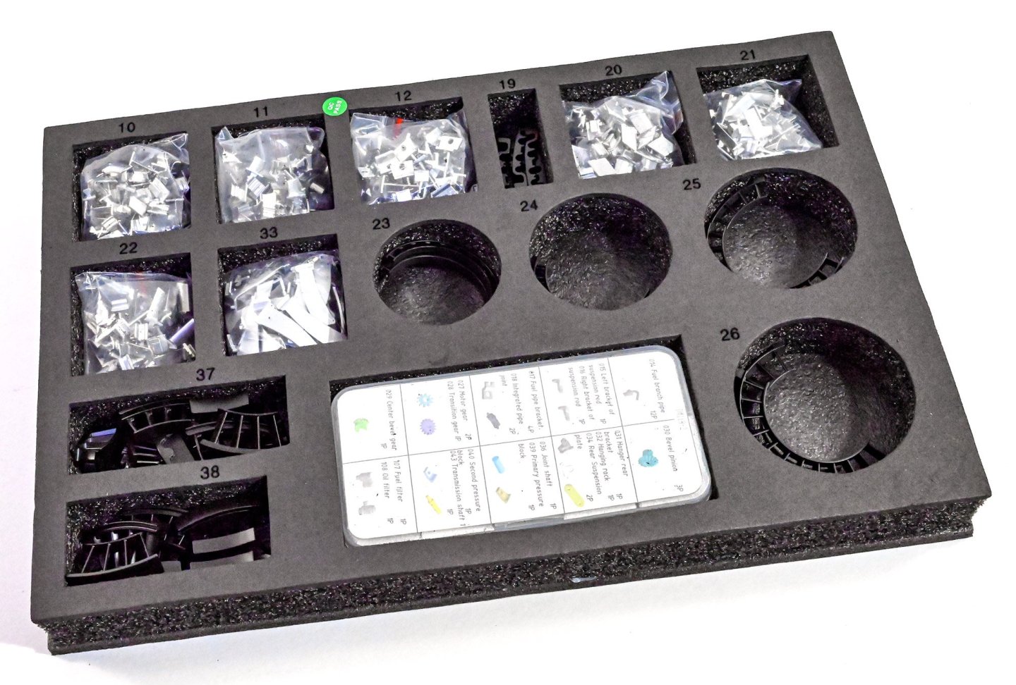
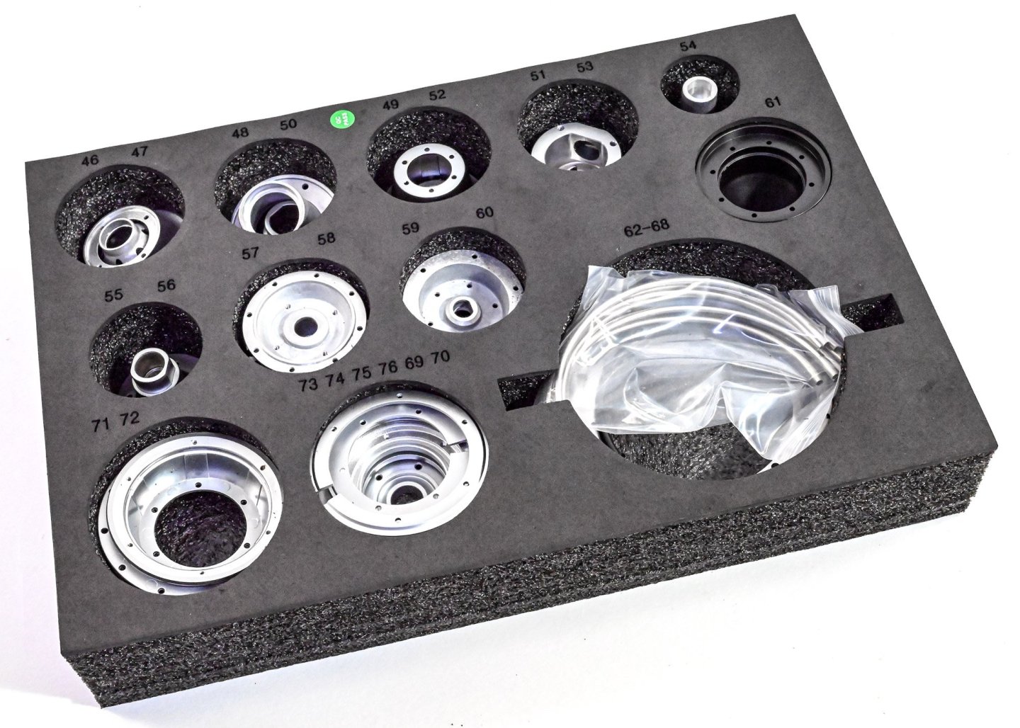

As you can see, many of the cutout have more than one part, but all are so carefully packed that nothing whatsoever is marked or damaged.

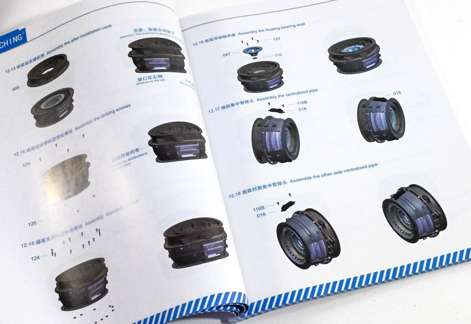
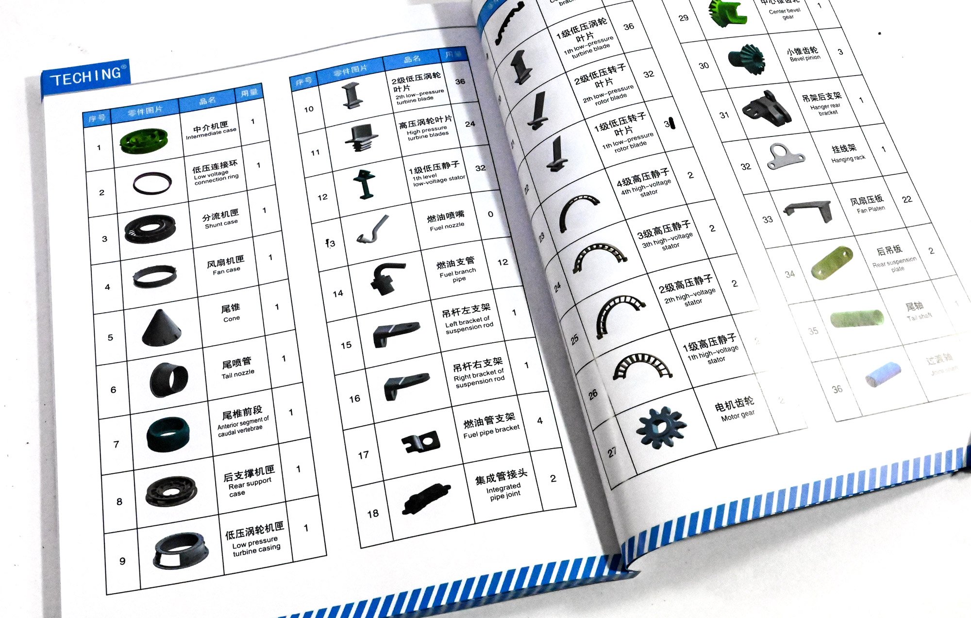
Instructions
This comes in the forum of a full colour, glossy 124 page publication, which details every single stage in wonderful clarity, with sometimes more than one single image to show a particular stage. The manual is published in both English and Chinese text, and not only includes the instructions, but also a little about the engine, some safety notes, and also a full colour parts key at the end of the manual. I didn't find a need for the latter, but it's there if you feel you need to reference it.


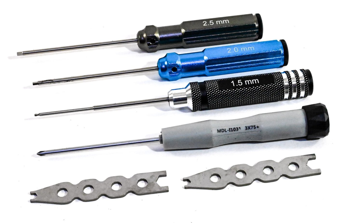
Tools
The model is also supplied with a set of tools. I did have problems with the 1.5mm hex driver as the head sheared off. That's no problem for me anyway as I wanted to use my own Wera tools. Some small spanners are also supplied.
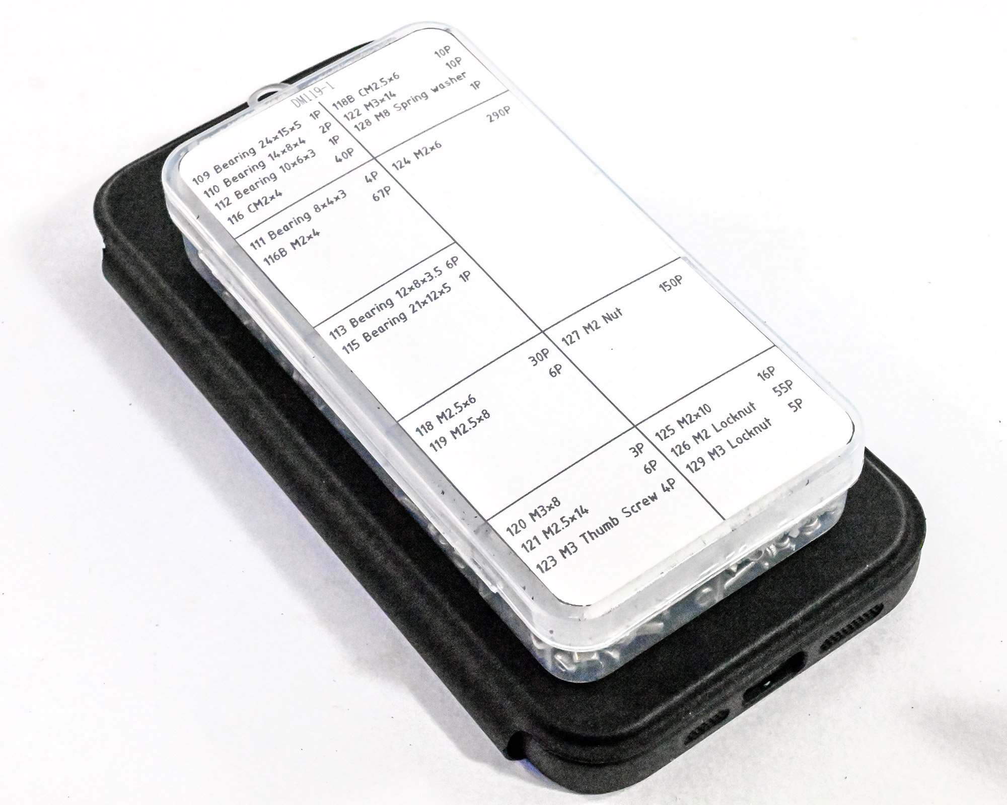
Fittings
Two plastic compartment boxes are included. As well as the screws, bolts, nuts etc, the boxes also contain bearings and other parts specific to this particular kit. All in metal.

Conclusion
You really have to like assembling mechanical models to get the most from this kit. There are LOTS of nuts and bolts to tackle and you'll need a reasonable bench area to store the various subassemblies as the build commences. The model is all metal in construction (apart from the clear viewing panels) and is something that really should not be rushed, and why would you want to if you are paying a premium for such a project. Tools are supplied with the kit, although my 1.5mm hex driver head did shear off and I continued with my Wera hex head set for most things. This is very much a precision kit and the excellent instructions need to be followed at each step. There are more than enough images for you to get orientation correct, and the text is very easy to follow, with no ambiguity. The only thing I would suggest is that you get a little model grease for the various gears, and a little lube oil for the bearings. The kit does have a space in the accessories box for that lube, but it's not included in the UK shippings, for reasons I don't know. If you've ever wanted to buy a model engine of a turbofan, then it gets no better than this one.
So what do I think of the kit in terms of build-ability? Well, we'll look at this over the next posts I make, culminating in a full build and video test startup.
My sincere thanks to Lucas at EngineDIY for the opportunity to build this remarkable kit on Model Ship World. To buy directly, click the link at the top of this article.
To get a nice fat discount on this kit, use the voucher code JAMESHATCH at checkout....TO BE CONTINUED.

-
Moved to correct forum area.
- mtaylor and Keith Black
-
2
-
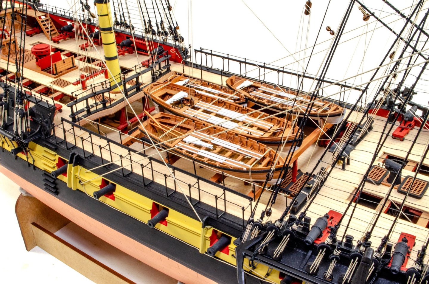
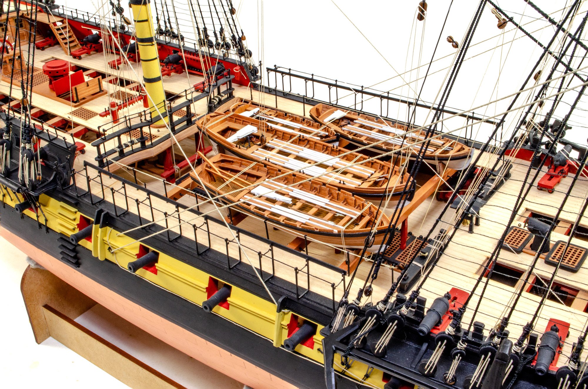
That is such a pretty planking job.
- FrankWouts, Thukydides, mgatrost and 2 others
-
4
-
 1
1
-
27 minutes ago, Beckmann said:
Very impressive and perfectly executed. Congratulation. Are you going to make a display case for the model? It will be huge.
Matthias
No, this one will have a new home in Scotland, so I don't need to worry about housing her permanently.
- mtaylor, Ronald-V, Ryland Craze and 1 other
-
4
-
1 hour ago, mugje said:
by the way...2 years with hiatus....still really fast 😮
I assume you still have a day job James?
About 7 months of that was spending 15 minute sessions then needing 2 or 3 hours mostly sleeping between them. Then Grecian was 10 to 12 weeks I think, so all that extended things.
And yes, I still have a day job!
-
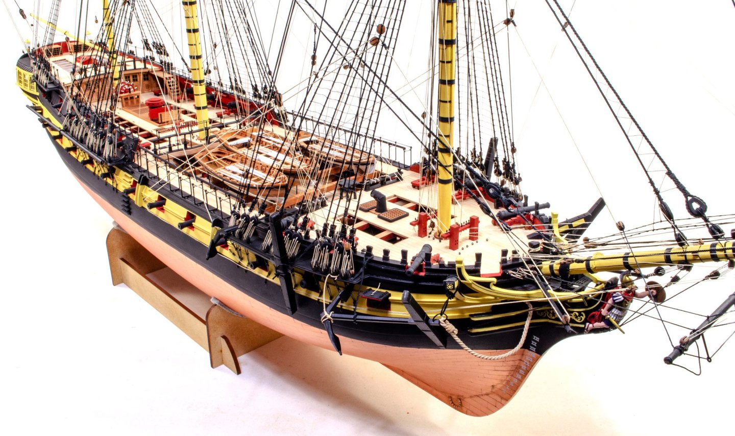
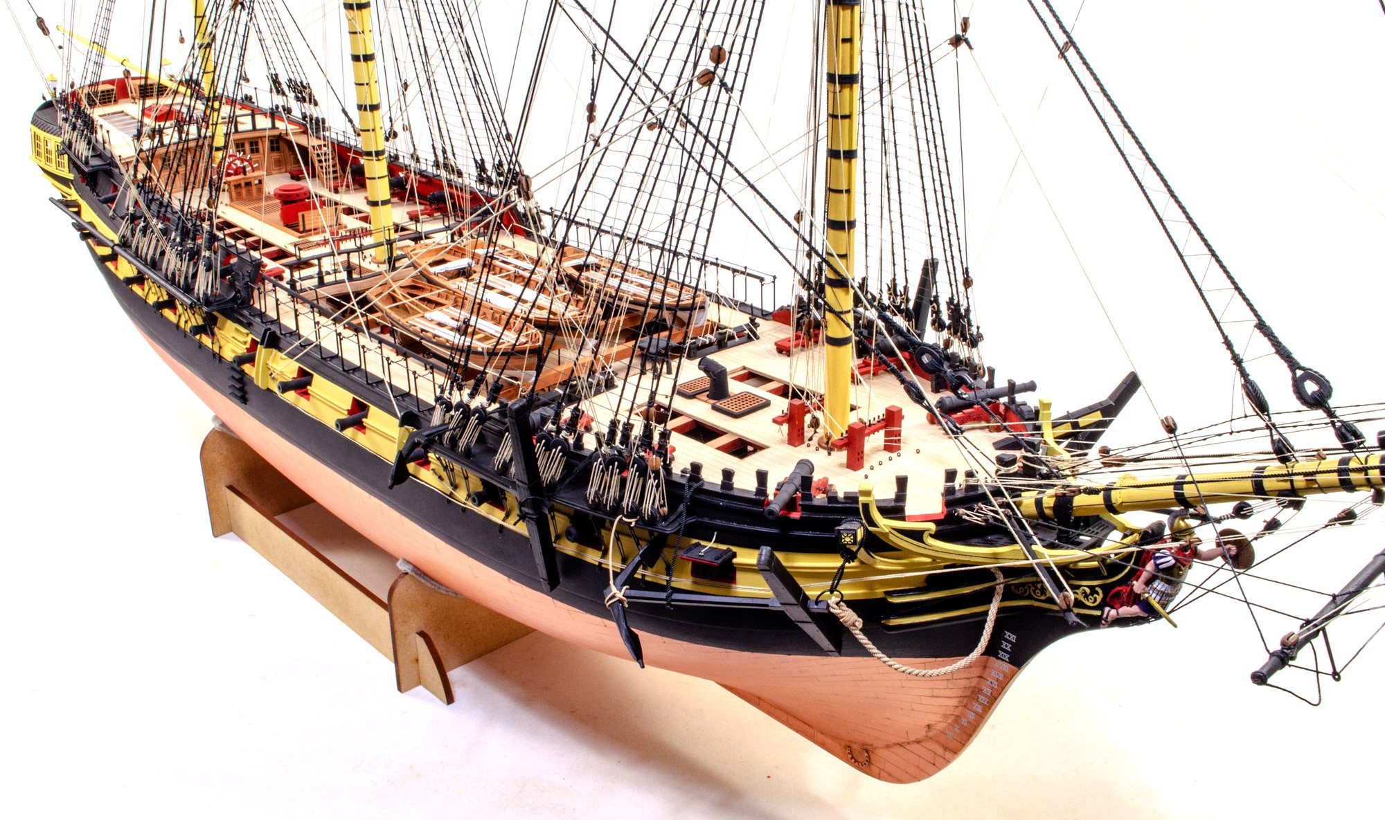
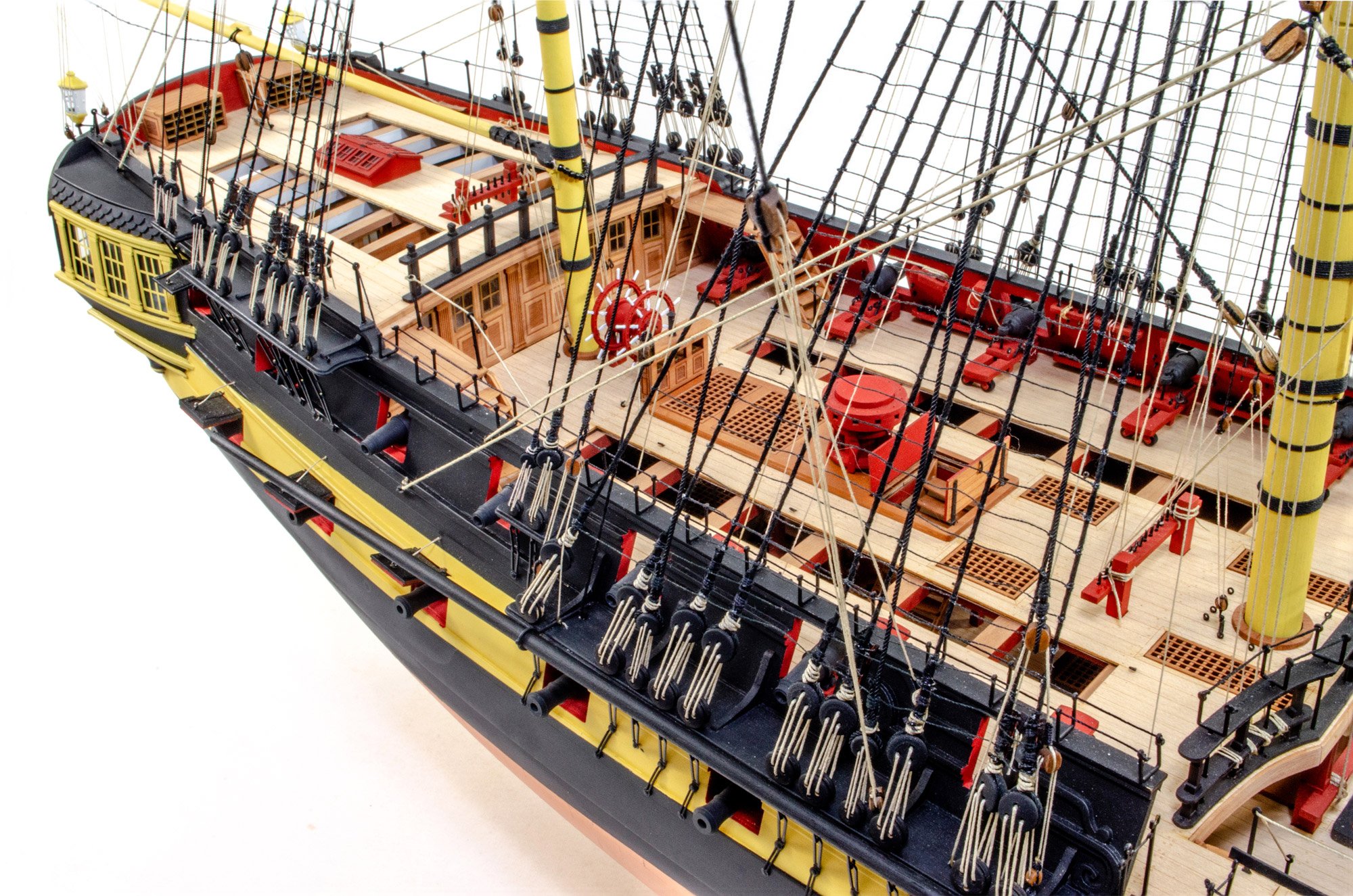
Well folks, this is it.
After 2yrs and 2 months, a period of ill health due to long covid, and also a break to build Grecian, here is my completed HMS Indefatigable. The rigging on this is intense but The last rig sheet went quickly. Hope you like her.


- petervisser, Chuck, jpalmer1970 and 52 others
-
28
-
 27
27
-
-
-
5 minutes ago, Cristiano said:
.....so the modeller is forced to purchase the sheets apart if he want to complete the model.
A modeller could just use copper tape of the correct width and then cut the plates themselves. This approach has been used on VM's Grecian, HMS Indefatigable, and very soon, Harpy.
-
-
-
25 minutes ago, navarcus said:
Wouldn't the purple smokestack's (vent?)
opening face forward because the wind comes from aft?
Remember, the ship is travelling forward, pushed by that aft wind. If the stack was facing forwards, there would be a positive pressure at the vent, forcing smoke under the deck. Facing backwards, despite the wind, there will be a negative pressure, helping to draw out smoke.
-
That's a nice look under the hood.
I definitely can't understand the lack of deck camber in modern kits. Looking forward to seeing you build this one.
- chris watton, catopower, Ronald-V and 2 others
-
5
-
-
-
-
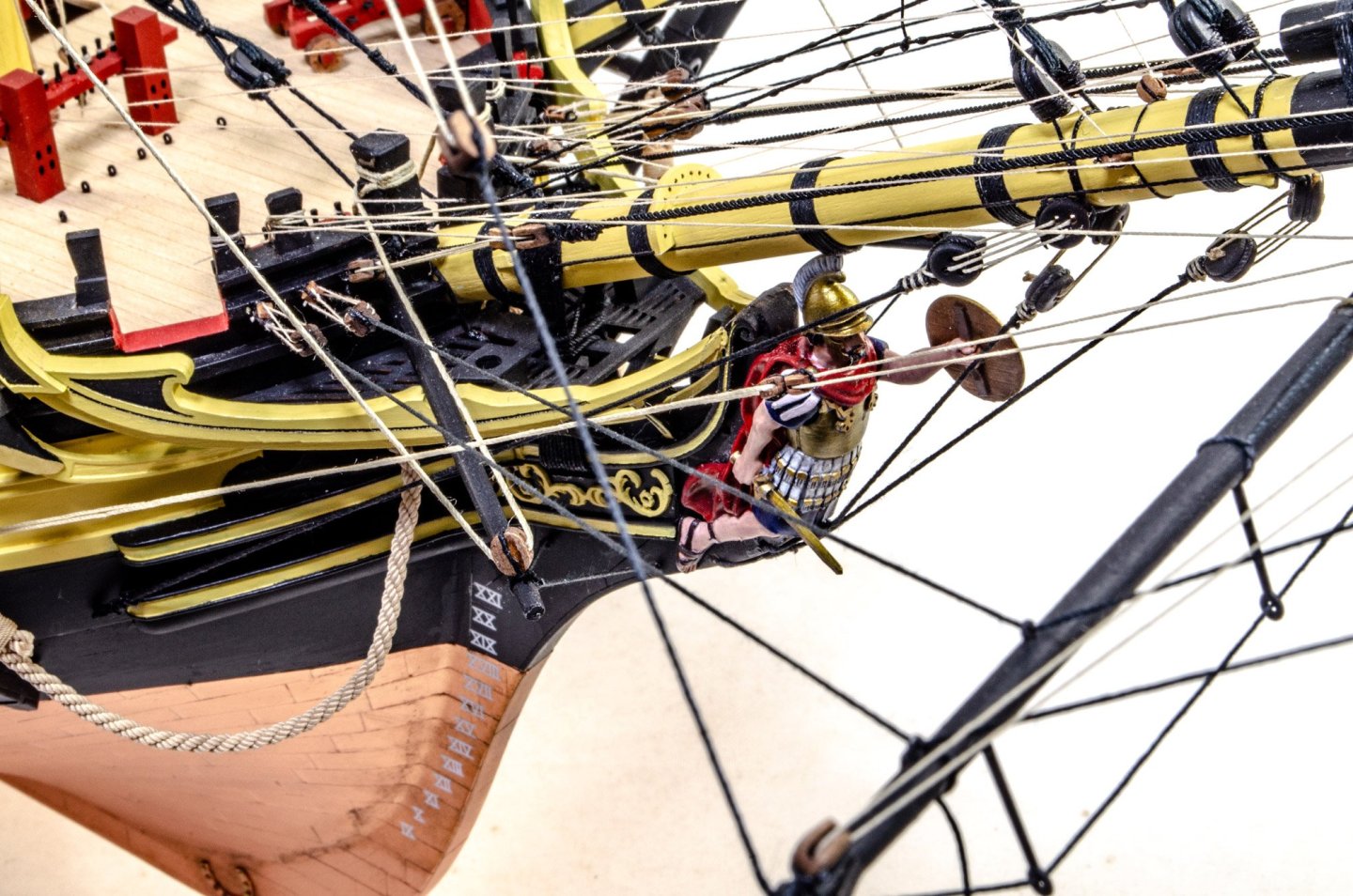
Beautiful work.
I can't imagine they are quick to carve.
- Ryland Craze, Canute, Nirvana and 1 other
-
4
-
If someone here has the knowhow, maybe they can make a vectored one in PDF form, that can then be scaled and printed to whatever size.
- brunnels and hollowneck
-
1
-
1
-


1:10 Turbofan Engine - Teching (build review)
in Non ship-related reviews
Posted
Onto the final leg of building the turbofan.
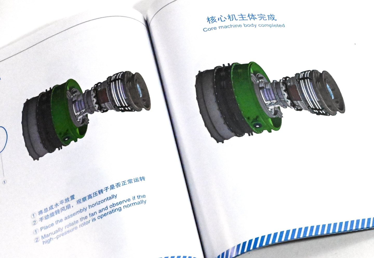
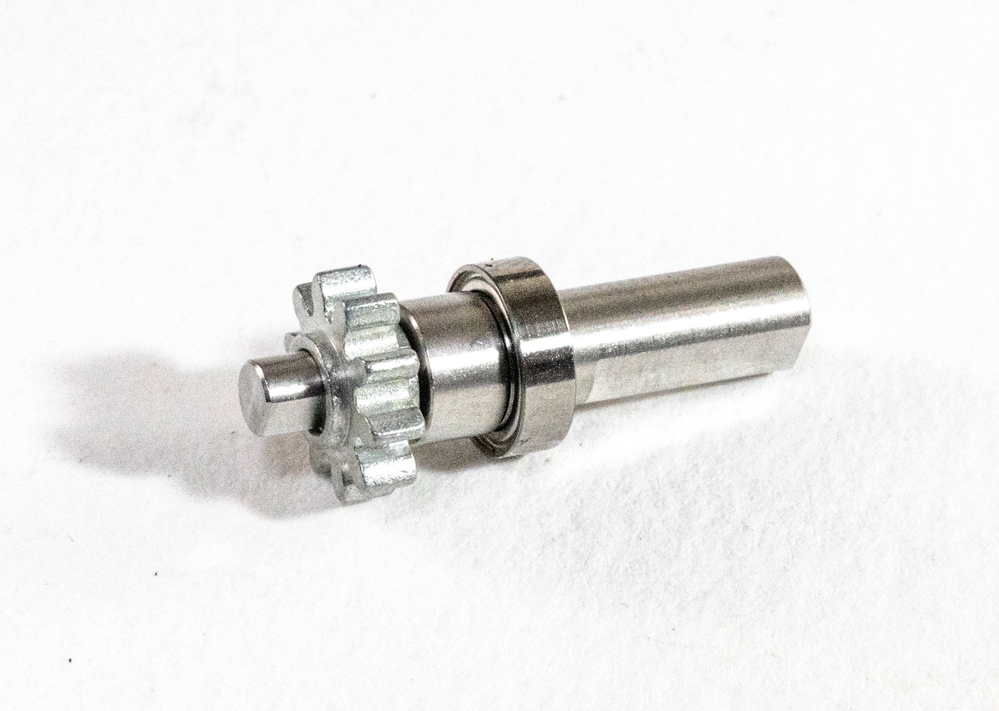
The intermediate casing is now used and fitted with the parts I've just built, as well as inserting a secondary drive shaft through the casting, to the outside, where a gear is installed.
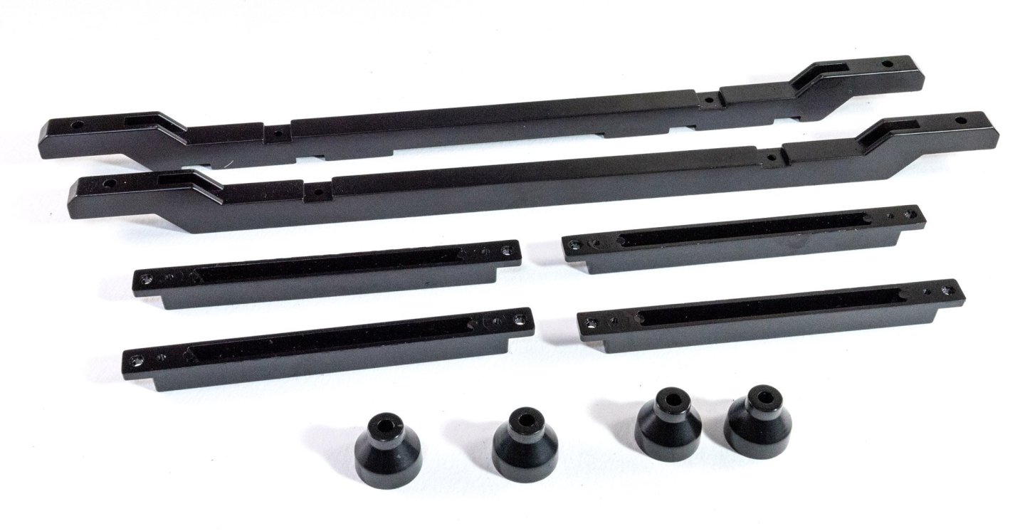
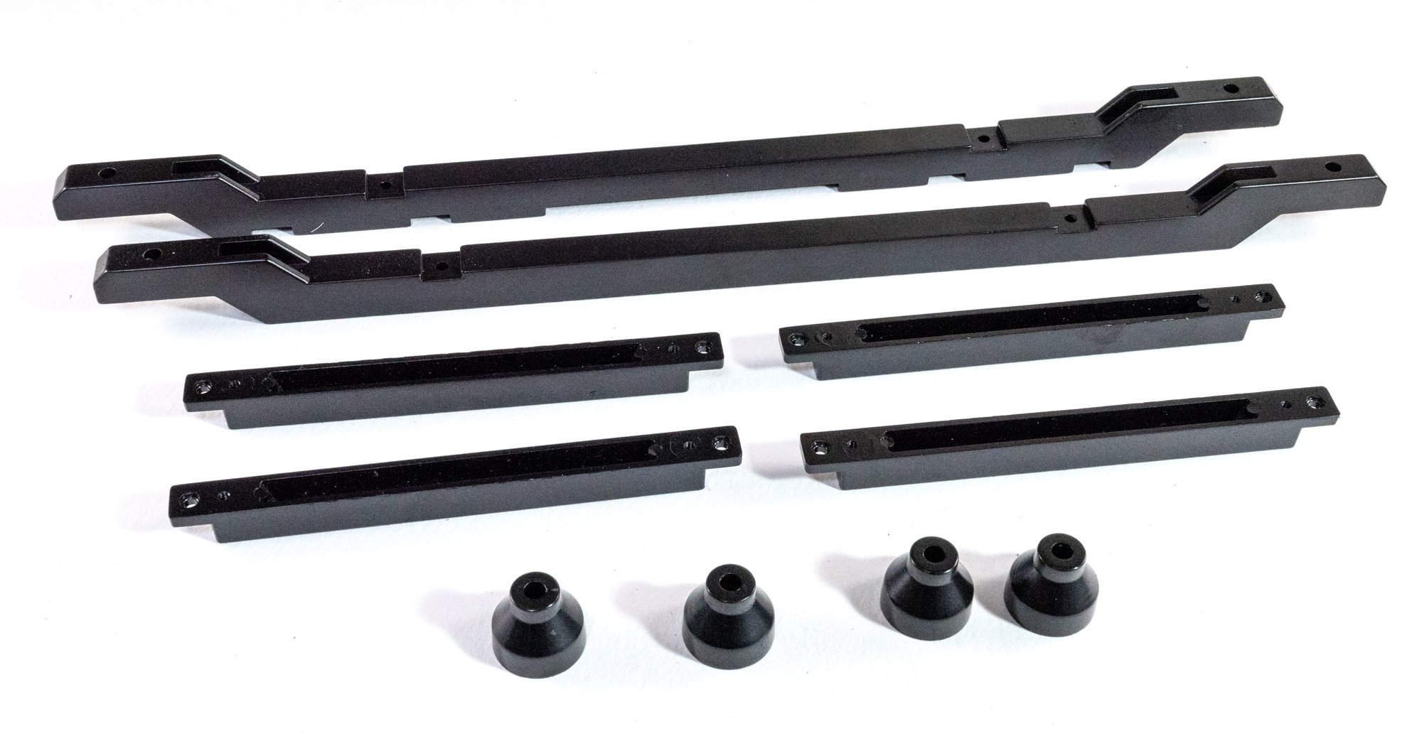
The sealing plate is now attached, as well as the brackets which will hold the tie rods.
After fitting its bearing unit, the casing is connected to the forward low pressure casing unit.
....followed by the high pressure stator case.
The next in line to be fitted to the engine is the combustion chamber.
The high pressure turbine is now interred.
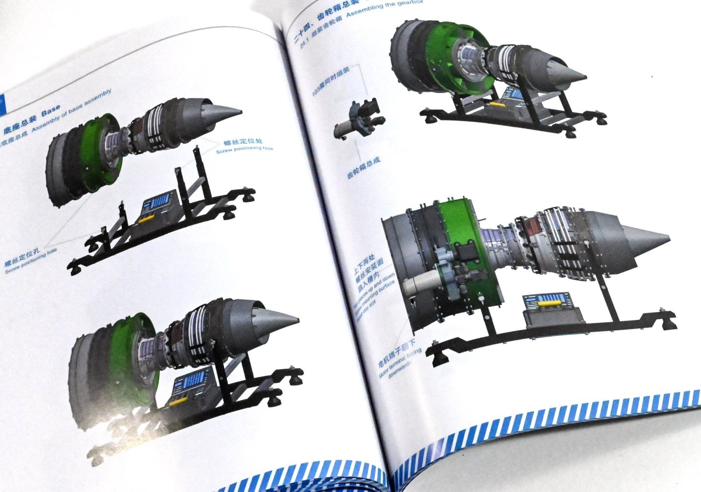
The anterior vertebrae is now fitted to the back end of the combustion chamber, followed by the cone and the tail nozzle.
This grand looking engine now needs to be fitted to the test cradle so that it's easier to work on.
The electric motor drive unit is now fitted to the low pressure fan casing and some model grade used for lubing the gears.
The ties and some other external engine details are now fitted to the engine.
And she is now complete!
I really have to say that this has been a blast to build and despite the high price of the unit, you are left with an extremely heavy and beautiful replica of a turbofan that you can power up and see working. This has taken me a week of evenings to build, and part of a weekend, only broken up by waiting on some replacement parts which came very quickly from China. Would I recommend it? Absolutely! If your budget can stretch to this behemoth, then she will look great on your office desk or cabinet.
Here she is, working...