thibaultron
-
Posts
2,952 -
Joined
-
Last visited
Content Type
Profiles
Forums
Gallery
Events
Everything posted by thibaultron
-
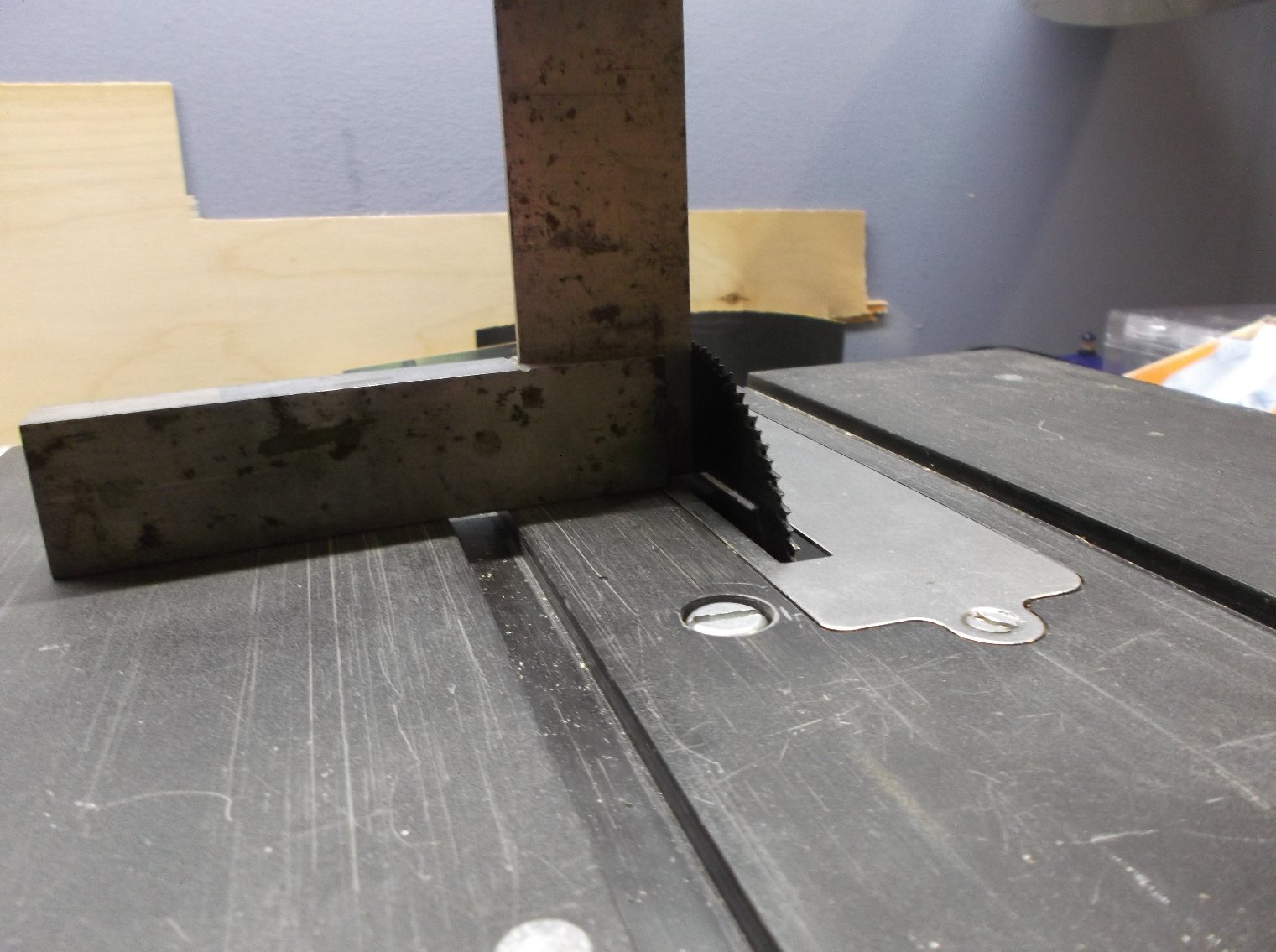
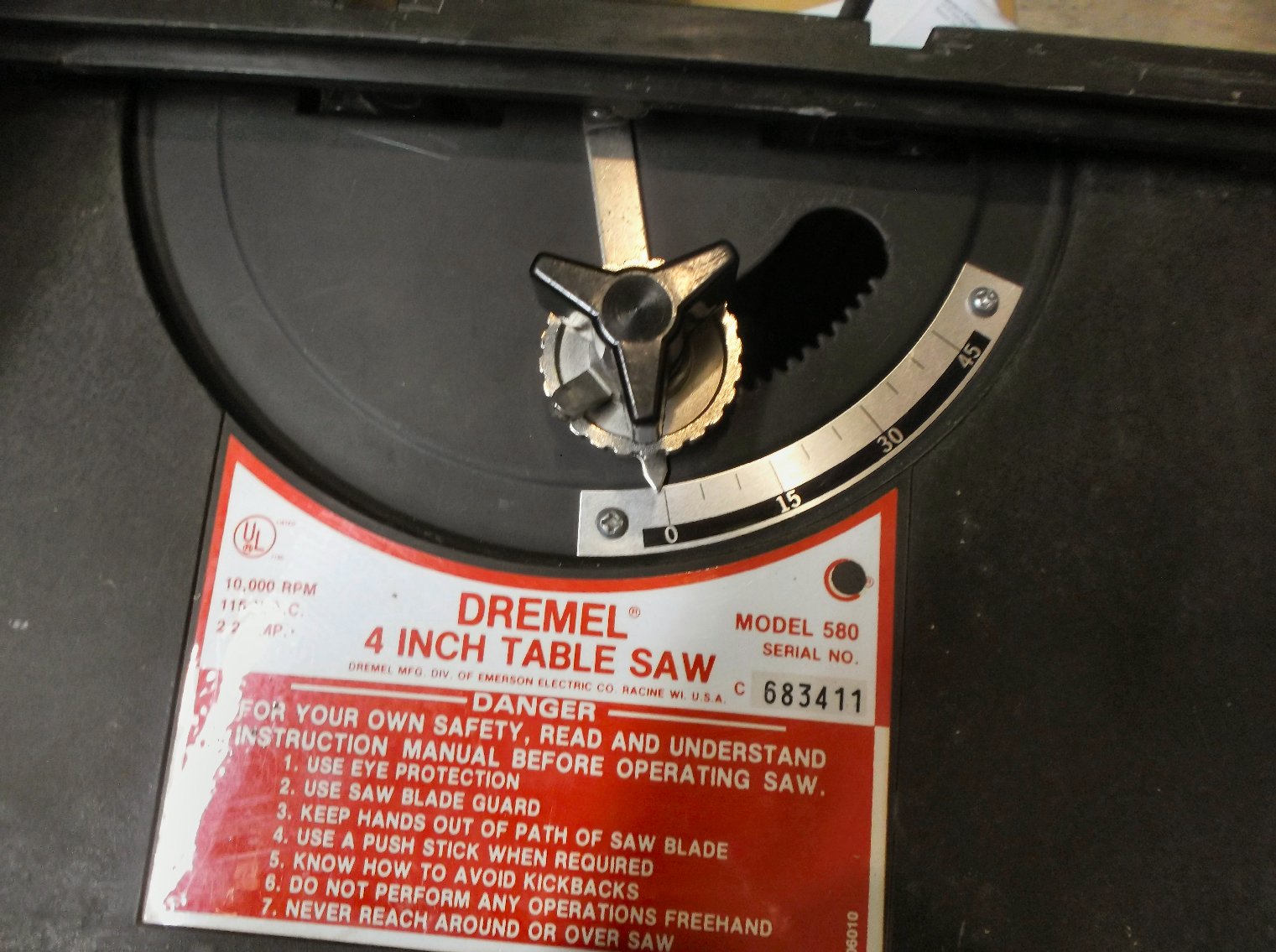
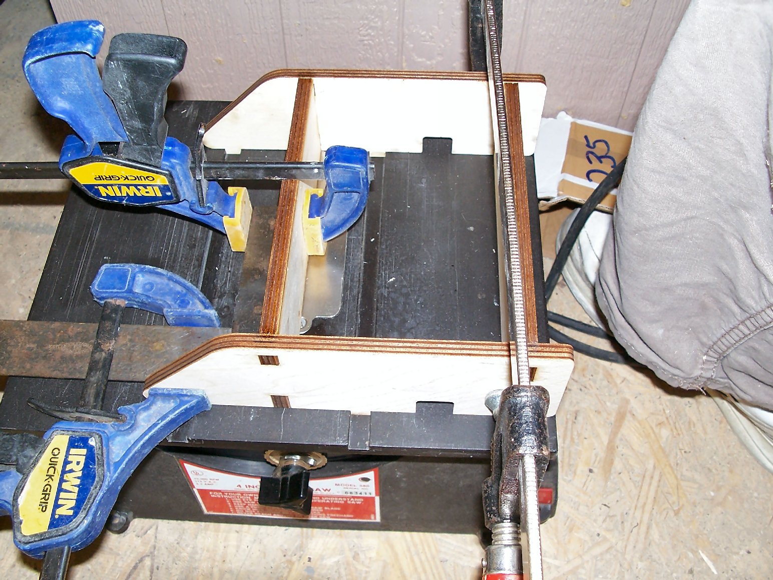
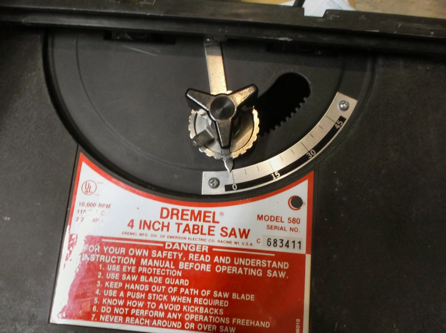
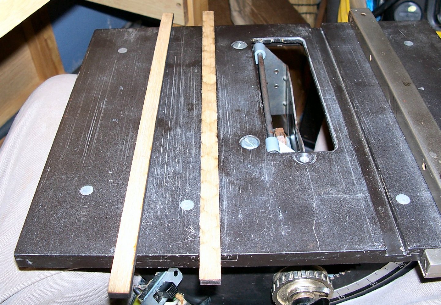
 Part 006 I’m sorry that I haven’t posted in a while. I’ve not had much spare time. Between work, some side jobs and my wife’s doctor appointments, I’ve had little spare time, and when I do, I’m too tired to get out to the shop. I found two saw blades on Ebay, for a reasonable price, so I bought them. I don’t know if I’ll use the 30 tooth blade, but I really wanted another 8004 – 100 tooth blade. I used the jig I bought to align the blade mechanism. I decided that using the jig to align the verticality of the blade was not going to work. I felt that there was too much blade flex to trust the jig, and with the shims I added to the tilt mechanism, it is now too stiff for the jig. Instead I tightened the mounting bolts and used a machinist square to get the blade vertical. Then I loosened the bolts again, mounted the jig, and clamped the blade. Then I tightened the mounting bolts, aligning the blade assembly parallel with the miter groves. I checked the tilt gauge and found that it needed adjustment. This involved simply loosening the gauge mounting screws and sliding the gauge to match the pointer. In the previous picture of the jig on the saw, you see that I also used the jig to square the fence. No saw test yet, that will come soon.
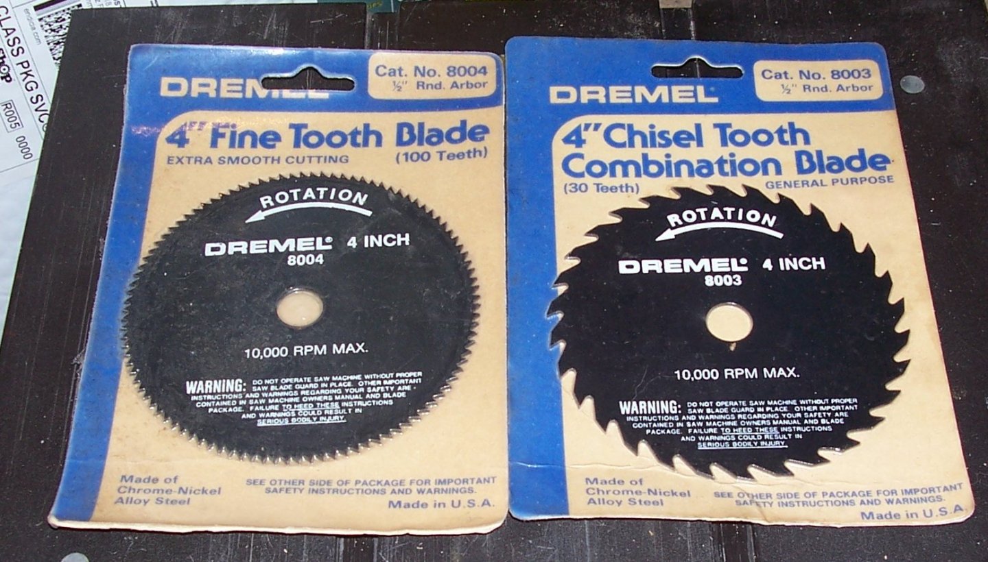

-
Homemade Spray Booth
thibaultron replied to BETAQDAVE's topic in Modeling tools and Workshop Equipment
Sharpen a wide chisel, buy a couple of lengths of square metal keystock. Then clamp or screw then to the top, and run the chisel along them to flatten the top edge. Before I catch heat about running a chisel edge across metal, use a cheap chisel. -
The B-17 gunship was the YB-40. Basically added another dorsal turret, and made all the single mounts dual mounts. The bombay was used for ammo storage.
-
In the Italian bombing front, an Italain Ace was flying a captured P-38, and shooting down Allied bombers who were mistaking it for one of their fighters. There was a version of the B-17 that was fitted out with extra guns, and no bomb load. Its fault was that the other bombers got faster after they lightened their load, after dropping their bombs, but this variant did not, thus slowing down the retreating formations. A pilot got the bright idea to have US intellegence investigate this ace. They found that was an insanely jealous man, who had been away from his wife for a long time. They then painted nose art on this B-17 with some saying and a likeness of his wife. Sure enough on a run shortly there after, he spotted the plane and attacked it, and they managed to shoot him down. They did not get away without damage and injuries, but they got him.
-
Look on their web site, last time I looked they sold the plans for all their kits.
-
Guys, I'm about your age. I just want to say, that I was never one of the ones that disrespected the Nam Vets and that you for your service!
-
So, what was the quick way you used?
-
I'm in.
-
You need to notch the two bottom planks to fit around the raised section of the keel.
-
Homemade Spray Booth
thibaultron replied to BETAQDAVE's topic in Modeling tools and Workshop Equipment
I like the tear off tape idea! Thanks for the tip! -
Yes, the B-17s were tough beasts! In one amassing incident, a German fighter flew through the fuselage of one by the tail, it cut the hull al the way through, except for an 18 inch section. Luckily this area was where the control lines ran. The plane made it all the way back to base safely. The fuselage finally broke during landing, with the added stress of the tail wheel touching the ground. Everyone in the crew survived.
-
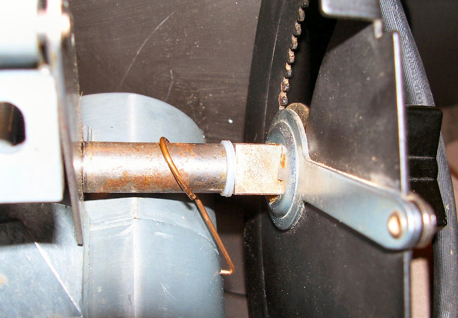
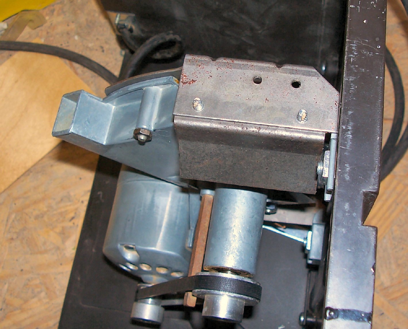
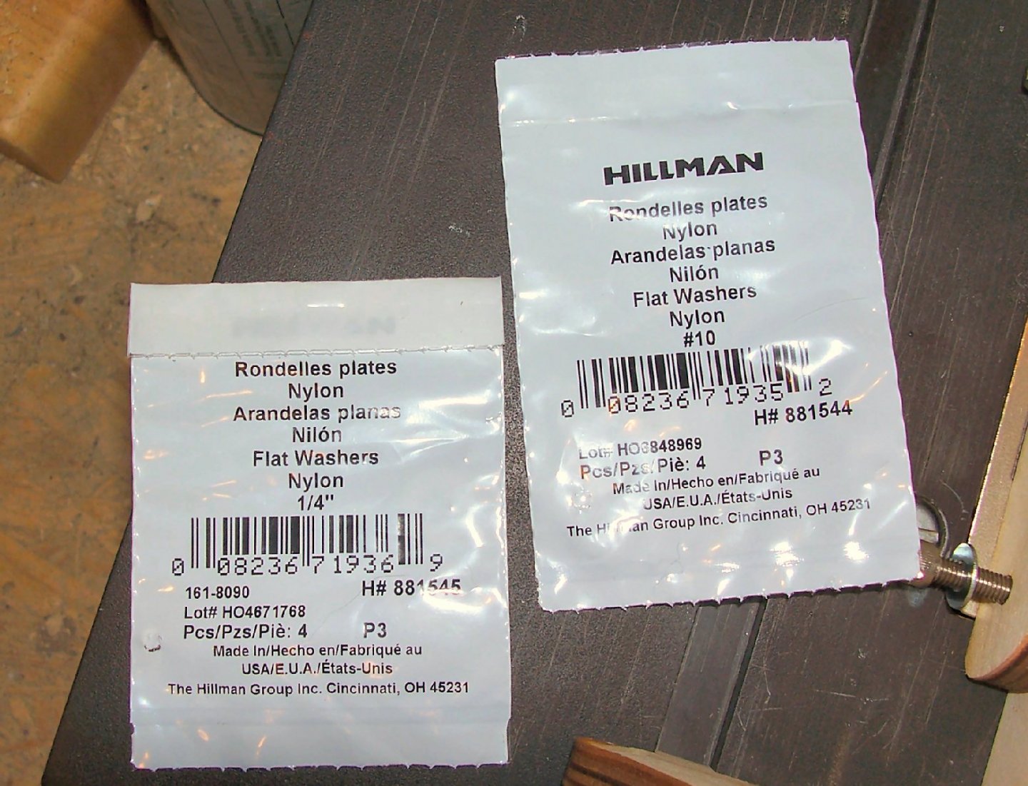
Part 005 I stopped by Lowes today and bought some nylon washers, for the saw. I bought #10 washers for the blade drive assembly, and ¼” washers to fix the blade angle/lift mechanism. The #10s will replace the Mylar washers I installed earlier. I have a better feeling about their durability. The blade tilt/lift assembly was loose and allowed the mechanism to flop around a bit. Maybe not a problem, but I don’t want it to change angle, even slightly, while I’m cutting. The shaft that raises and lowers the blade, runs through the center of the block that adjusts the blade angle, there is a gap between this shaft and the block that allows the assembly to flop a little. I slit one side of two of the ¼ inch washers and inserted them into the gap (yes it was “fun”). This tightened up the assembly quite well. By the way the copper wire you see, is suppose to be the spring that holds the shaft into position. Being copper it does not hold very well! I’ll make a new one out of some brass or steel wire. There is still enough movement that I think I’ll add a second adjustment point at the back. Nothing fancy, just a curved slot with a screw I can tighten when I get the blade at the angle I want. In anticipation of this I installed the angled blade cover on the inside of the assembly, rather than at the back, like it came from the factory. I’ll grind the ends of the screws off, when I build the back.


-
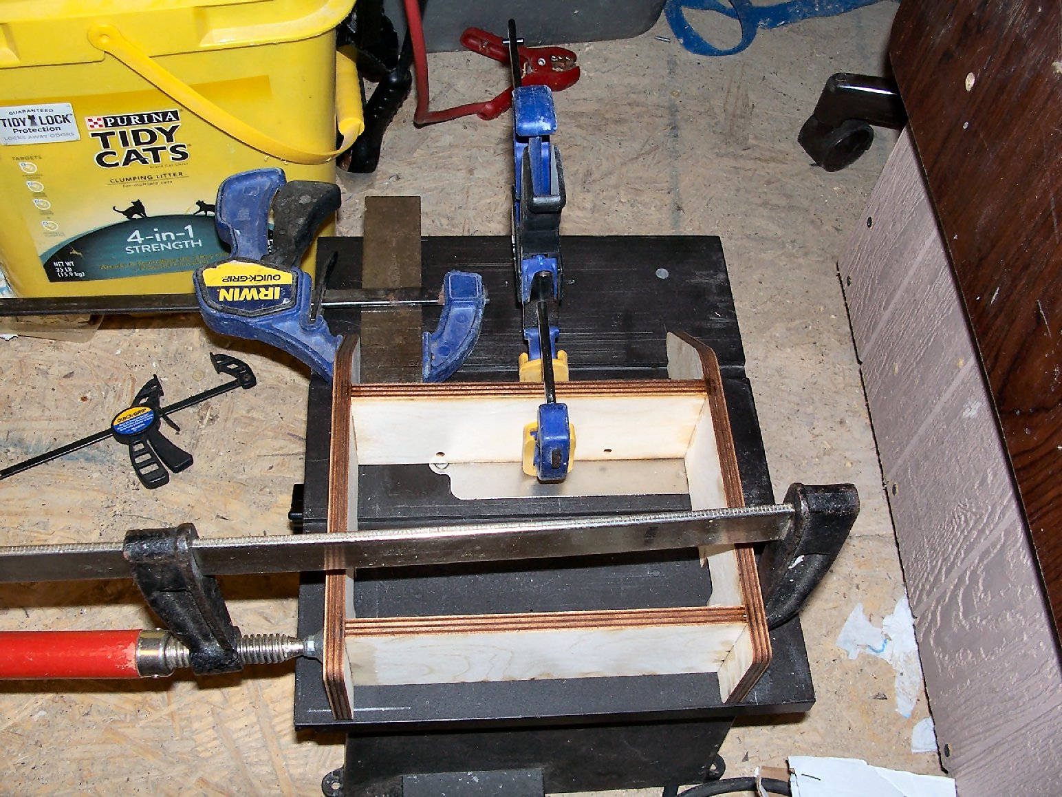
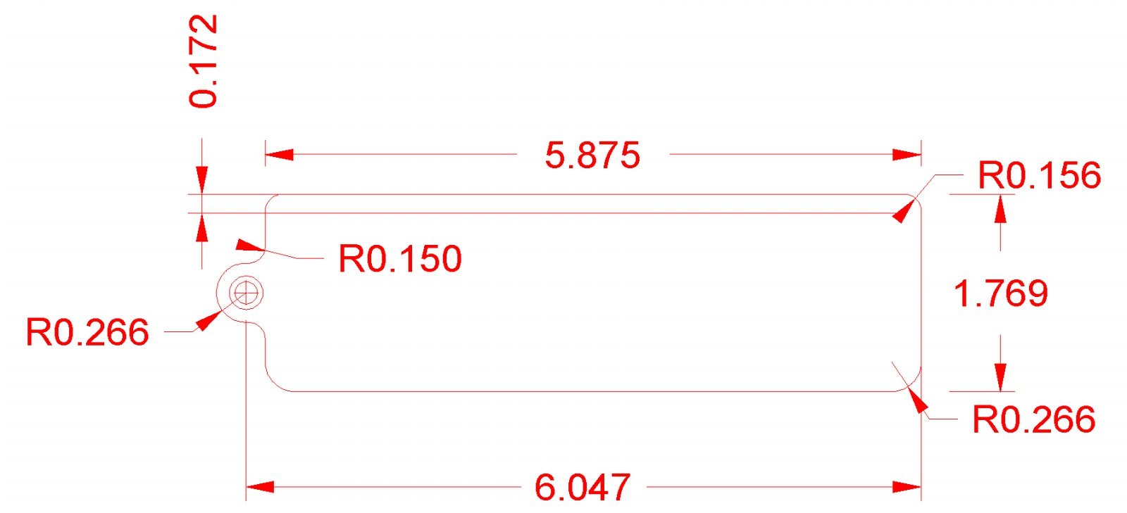
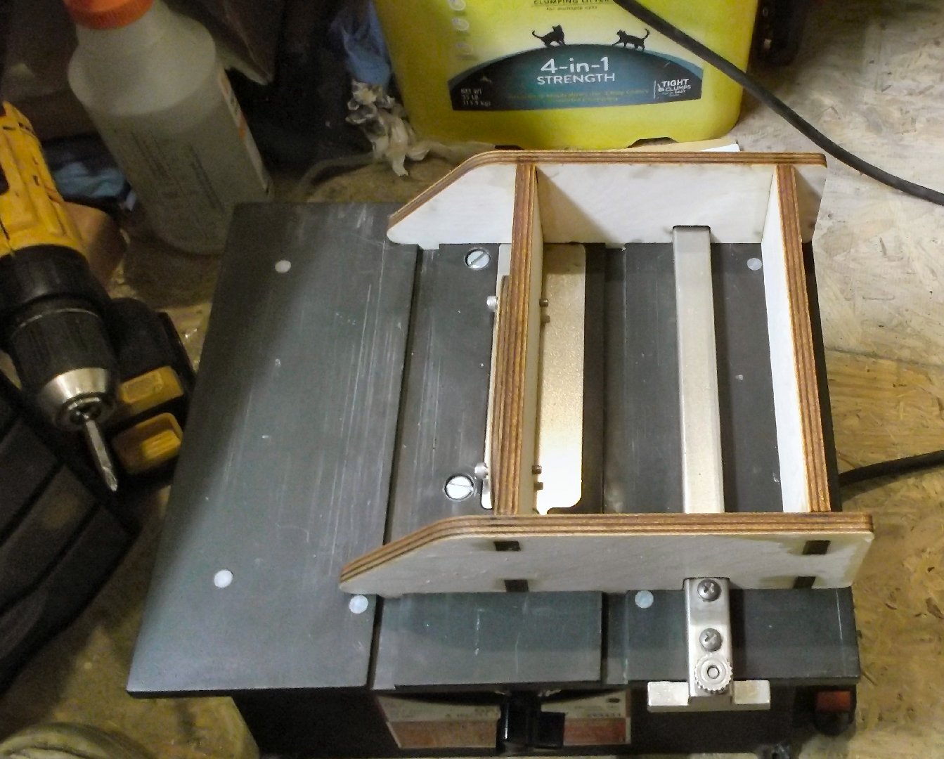
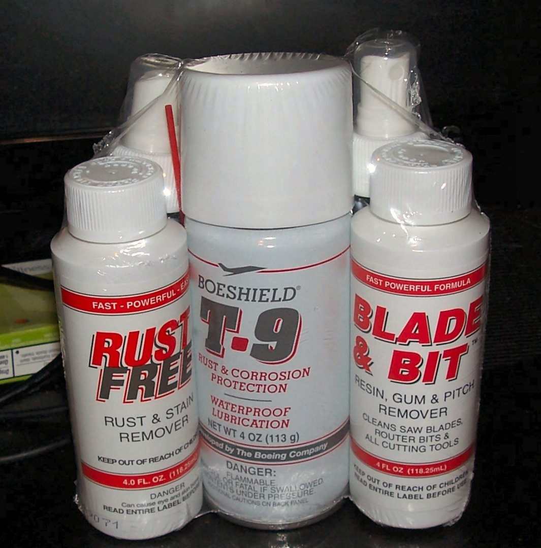
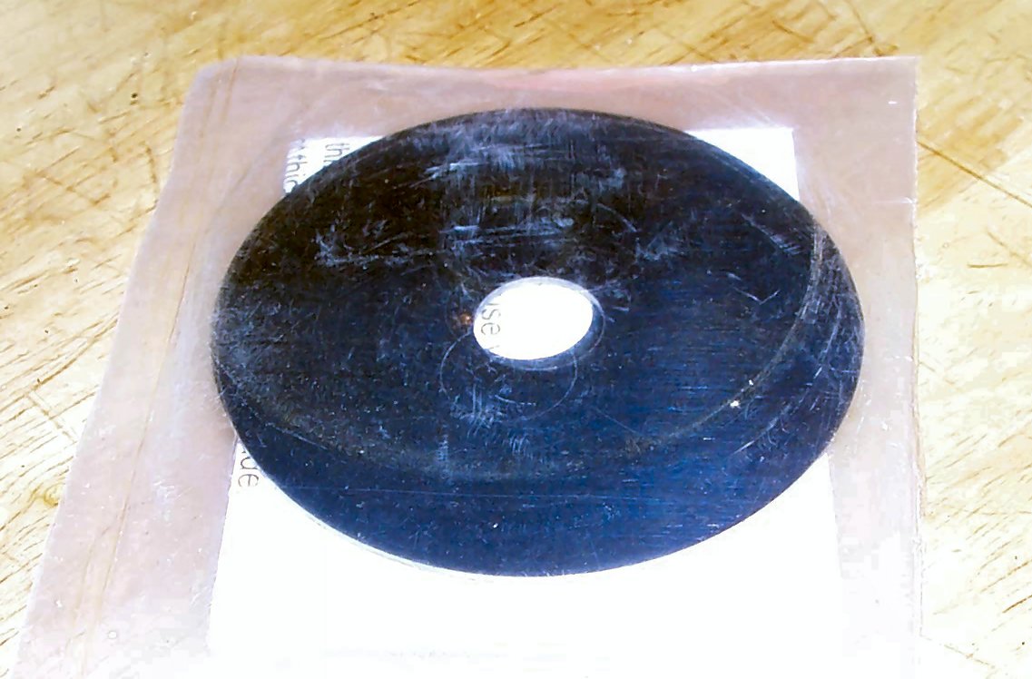
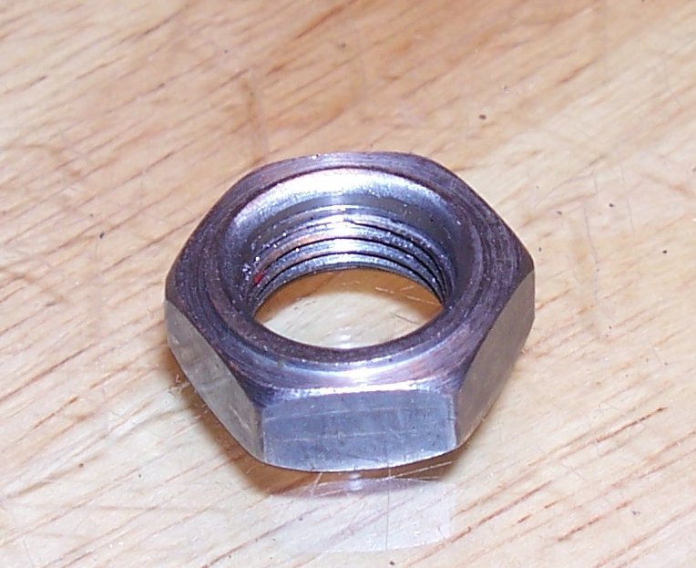
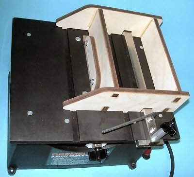
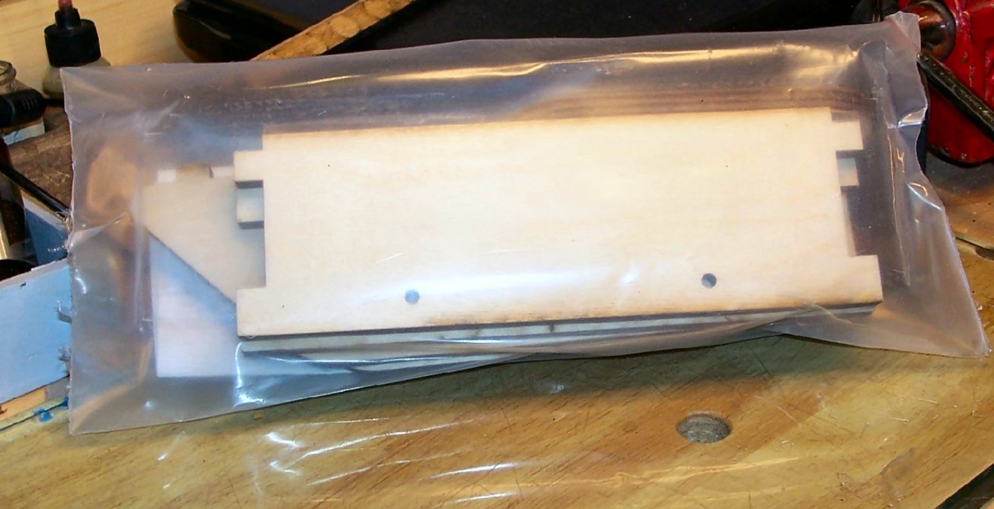
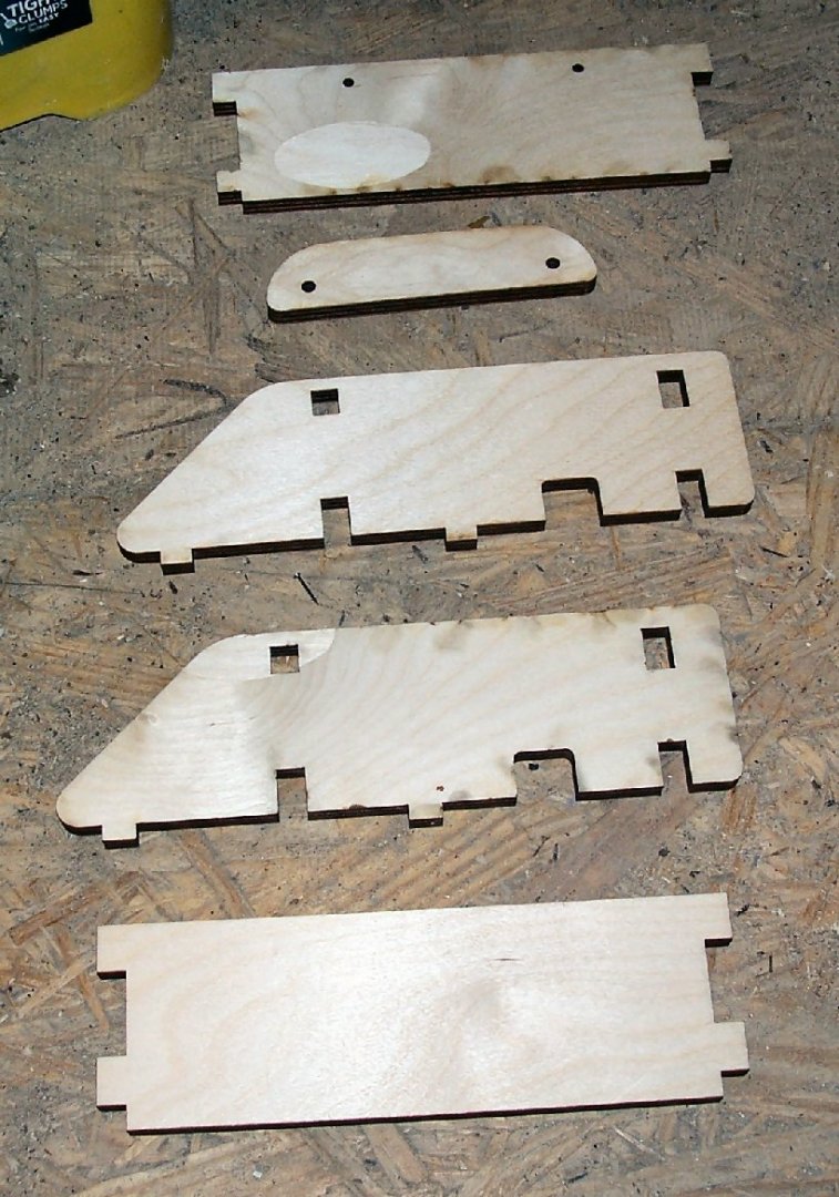
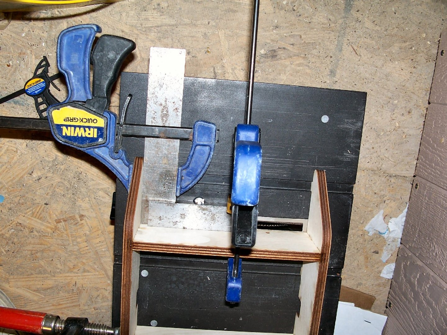
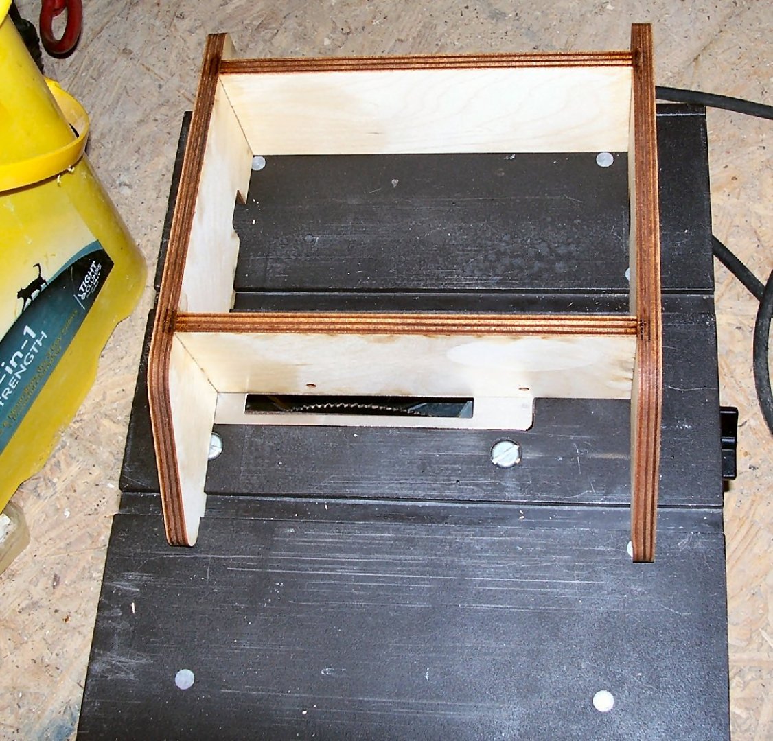
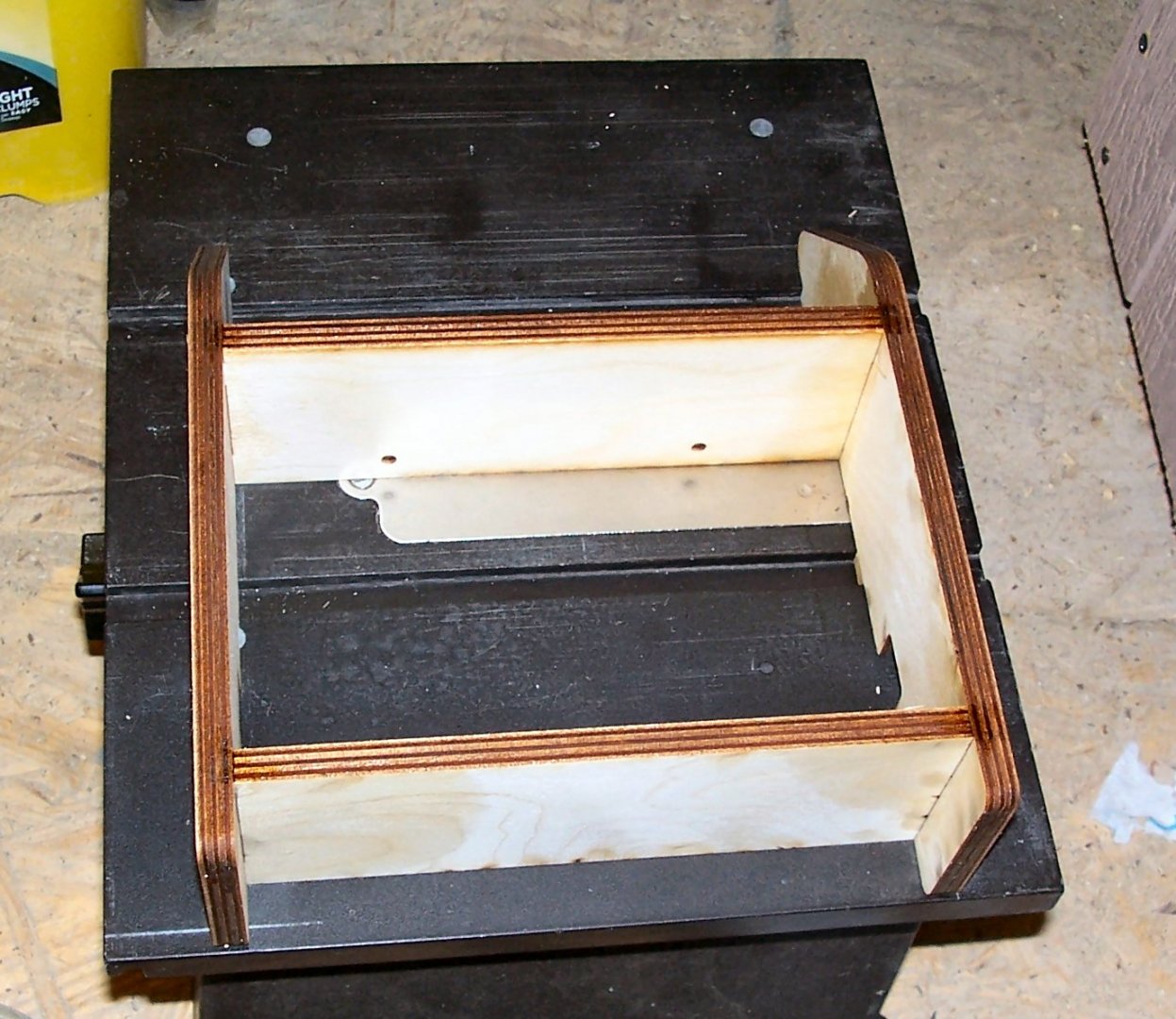
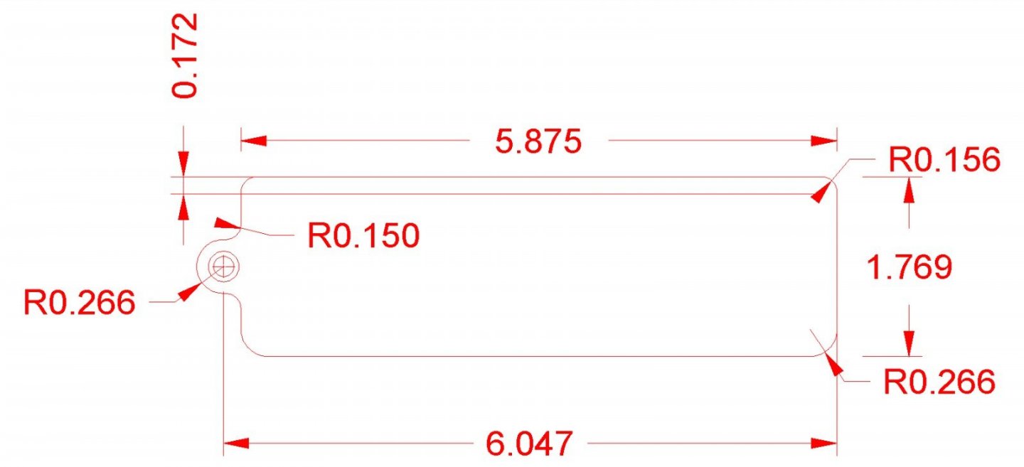
Part 004 A quick review of the Boesheild products I used in the last installment. The Rust and Stain remover and the blade cleaner, both worked well. The protectant did not work as well as I had hoped. The metal stayed “wet” and after several days I had to wipe the parts off to get them to dry. I think that there is a wax coating on them, only time will tell. I ordered some accessories from Radical RC for the saw. https://www.radicalrc.com/category/Table-Saw-Dremel-Accessories-492 Here are shots of the parts. I’ll describe them as I go. These are laser cut slides for the miter slots. I’m going to use them to make a sliding table for the saw. These are support disks for use when you are using thinner blades than those the saw was designed for. These blades are typically the modern high tooth count ones such as 100 or 200 tooth blades. If I’m using the 100 tooth original Dremel 8004 blades, these are not needed. There are two disks in the package, one is placed on each side of the thinner blade. They both add stiffness to the thin blade and bulk out the total thickness so the factory nut can clamp the assembly. Without the support disks, the blade alone would be too thin for the nut to clamp the blade. This is a nut that is machined so that 5/8” arbor blades can be used on the saw, which is designed with a ½” shaft. This allows me a wider selection of blades to be used in the future. The last part I bought is an alignment jig for setting up the saw. Once built, it allows quick setup of the blade mechanism. The jig holds the blade vertical, and square to the miter slots. You loosen the blade assembly hinge bolts and clamp the blade in the jig. You can then tighten them, and the blade will be parallel to the miter slots. You then can move the blade tilt marking plate so that it falls at the zero degree mark. The jig also holds the fence in position, so that you can tighten the bolts that hold the fence body to the fence clamp, insuring that it is also parallel to the blade. Here is a picture from the catalog. Here is the package and the wood parts it contains. There are also two screws and washers for installing the clamp piece (the smallest wood piece). You are to assemble the parts on the saw table, and use a square to align the body pieces, then wick thin superglue into the joints. These photos shows the parts assembled on the table, with a machinist square clamped on to hold them square. I wish I’d had another long clamp for the other joint area, but I was able to hold the pieces with my hand. I carefully wicked in the glue one joint at a time, and let it set before moving on. I even managed not to glue the jig to the table! If I had a smaller square I would have clamped it inside the assembly rather than how I had to clamp the larger one. Once the last joint was set, I removed the jig, and wicked in more glue along the lengths of the joints. Here are a couple shots of the finished jig. I still have to install the clamp. I could not locate my Allen wrenches for the cap head clamp screws, yesterday. I’ll find them the next time I get to the shop. Next month I’ll buy a couple of the blank 3D printed saw blade inserts, and their aftermarket miter gauge. I also drew up a insert blank on my CAD program, so that I can design my own future inserts.


-
Use a modeling putty, not bondo! The bondo is much harder than the wood and would be difficult to sand without cutting into the wood. When you go to paint the model, seal it with shellac or varnish, before painting, if you will be using acrylic paints. Do a search in the forum, there was a thread a little while back , on the various methods of sealing recommended.
-
Well done!
-
I found the book both fasinating and helpful.
-
In model railroading, you can find a prototype for just about anything. One of the hard and fast rules, though, is never put a window in a chimney. However, when I lived in Pittsburgh, there was a house with just such a window in the middle of the chimney! A couple of years ago I found the house on Google Maps, and the street view shows that the chimney and window are still in place!
-
Chesapeake workboats had painted decks, so nails would not show. While the Sharpie is not specifically of Chesapeake origin, it would probably been treated the same for a similar use.
- 90 replies
-
- 1
-

-
- finished
- Midwest Products
- (and 1 more)
-
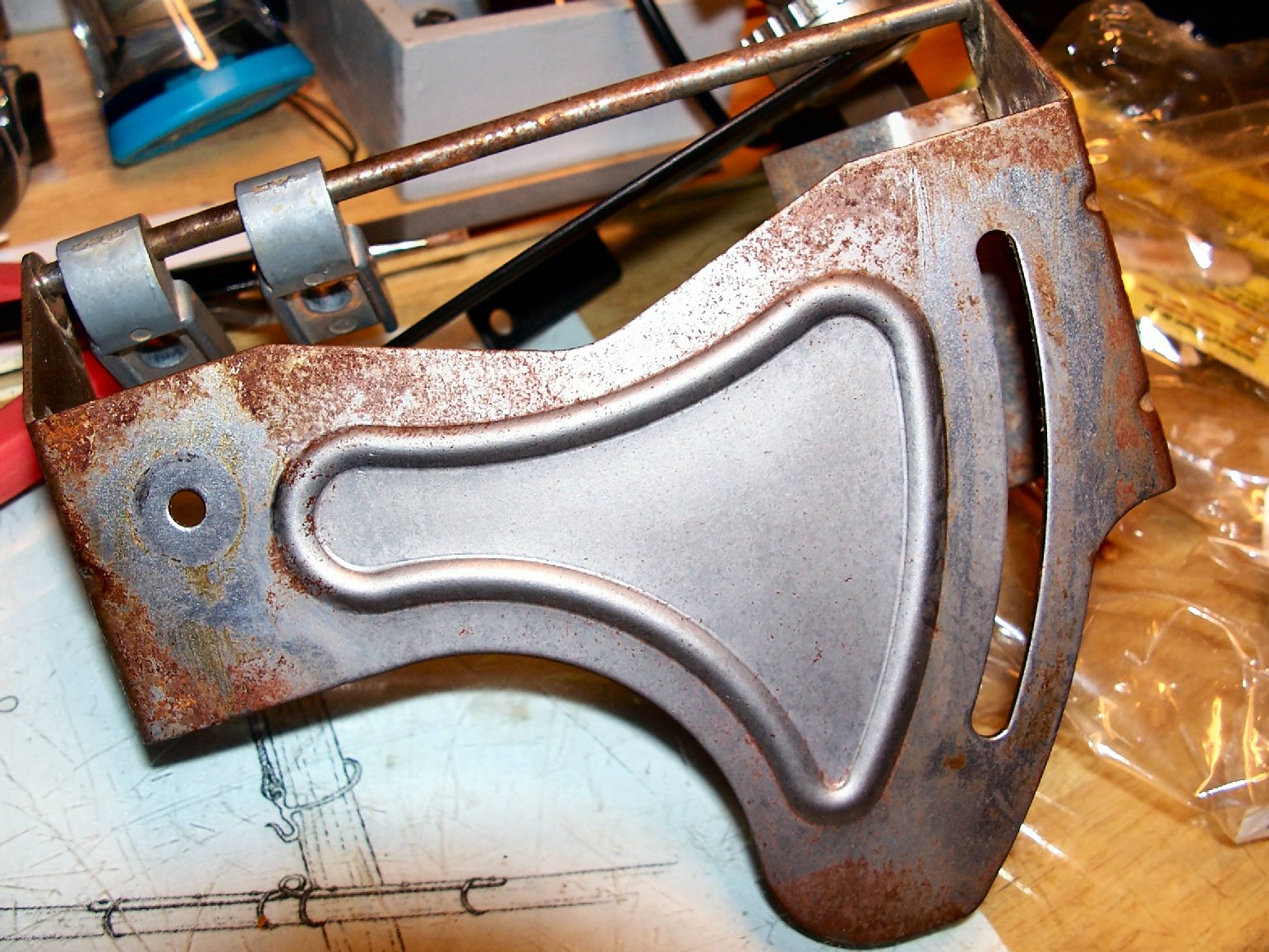
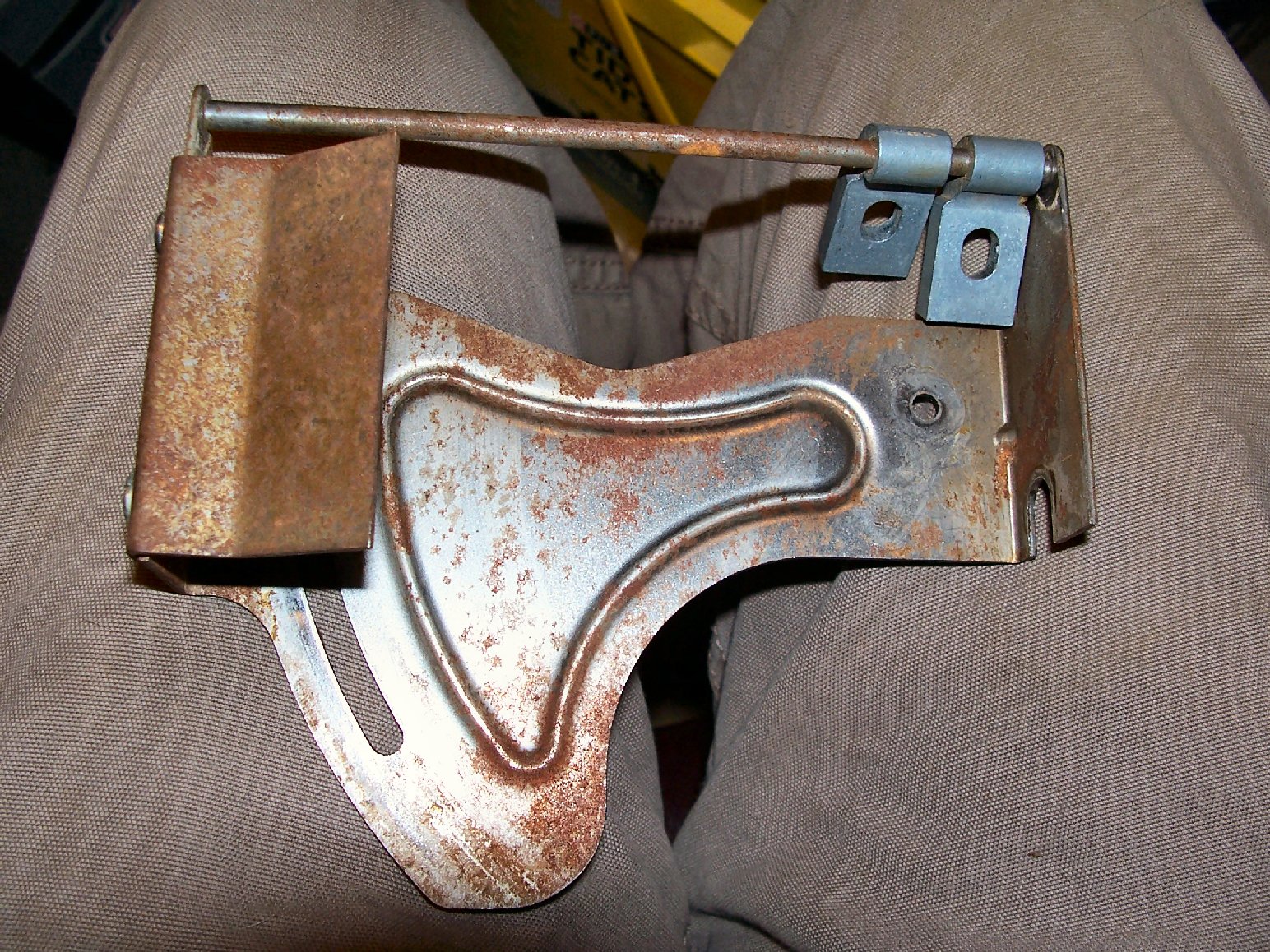
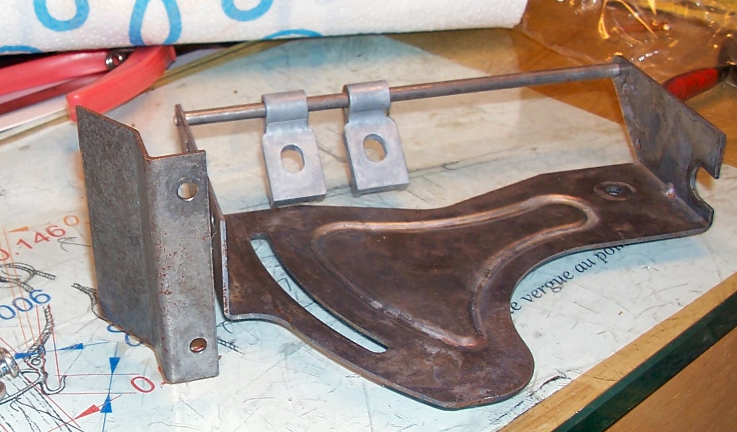
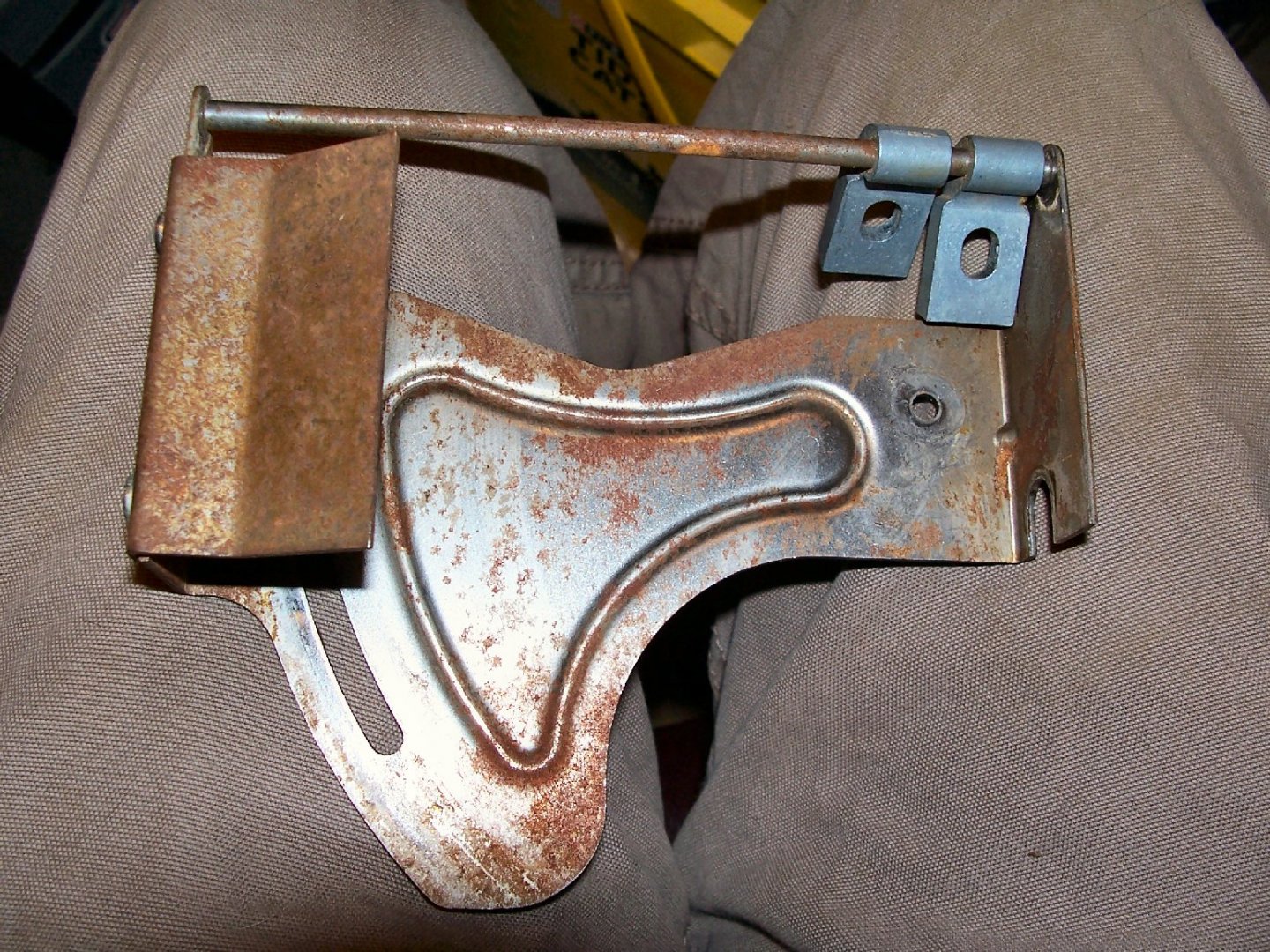
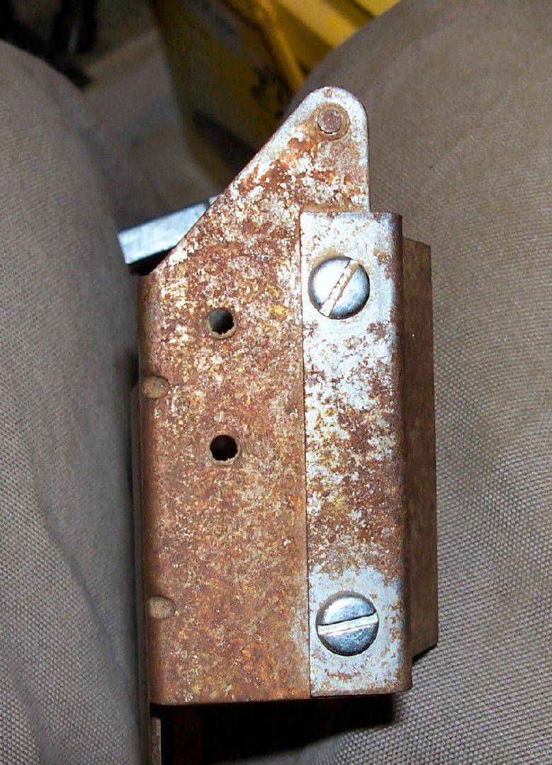
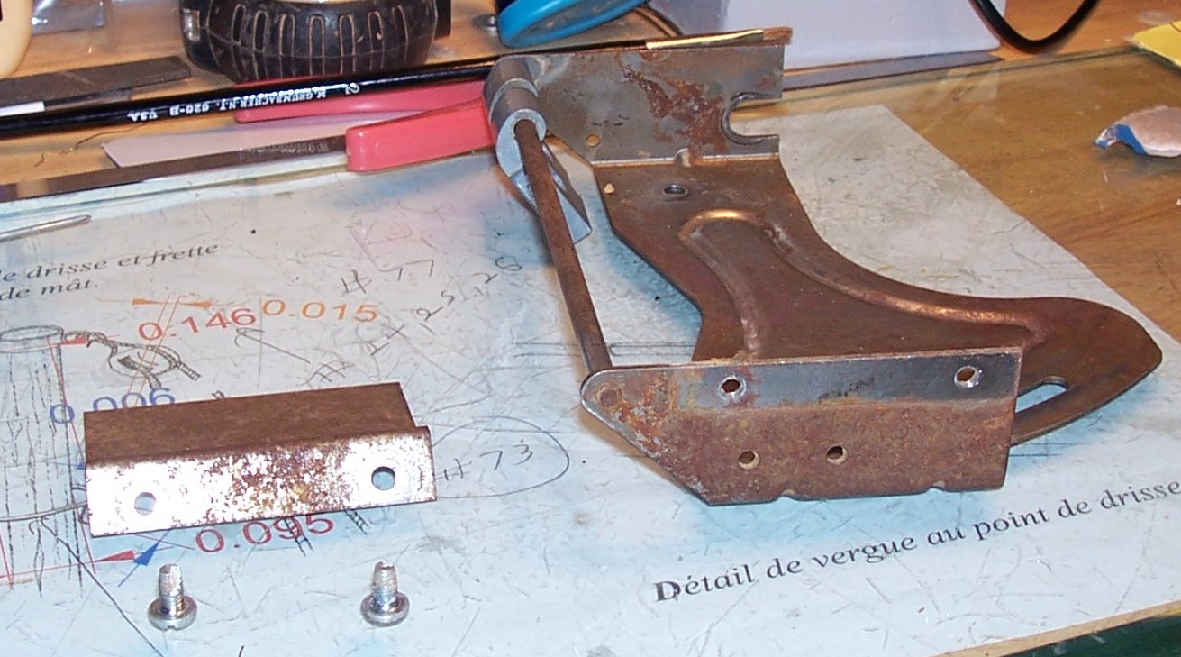
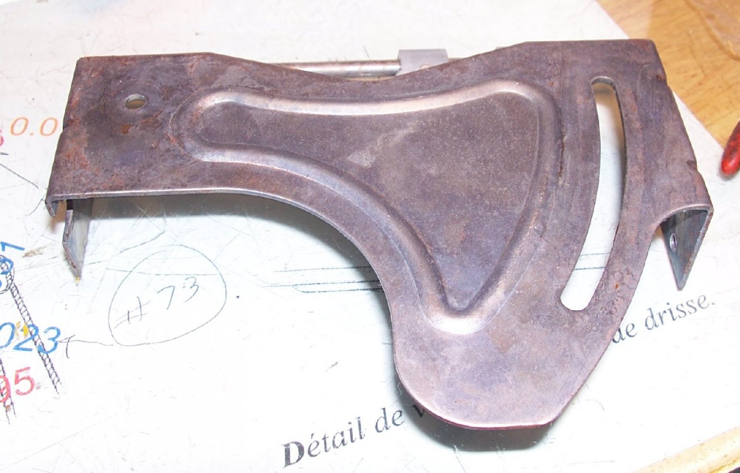
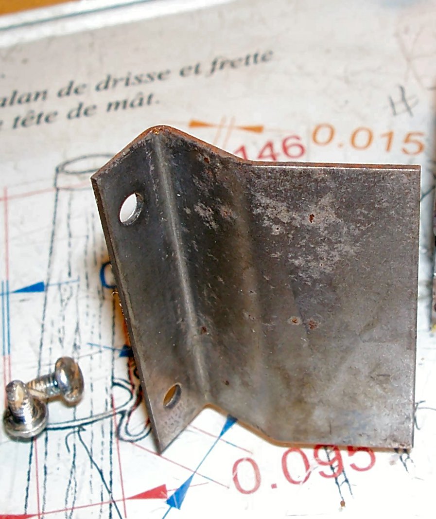
Part 003 I received the Boesheild rust converter/protector/blade cleaning kit recommended in the site I talked about earlier, and worked on cleaning up the sheet metal parts of the saw. The protectant and the resin cleaners are both recommended for wood working tools and are stated not to effect the finishing of the wood. Here are three shots of the sheet metal assembly, before I treated it. In the first shot I had already tested the rust converter on the inside of the center area. I disassembled the main and end pieces, so I could get to the area between them. I started with the smaller piece, spraying the converter on and using a green kitchen scrubby to work the solution into the pits, and loosen the flakes of rust. I then repeated the process for the rest of the assembly. The write-up I mentioned said to use a brass brush, but I could not find mine. Looking at the photos, the scrubby did not get down into all the pits, so I would recommend using the brush. In the last picture, you can see that the converter also darkened the galvanizing slightly. After rinsing the parts with water, I sprayed on the protectant. It seems to be similar to WD-40 in application. I set the parts to dry, as in the instructions on the can, and will check them out tomorrow.


-
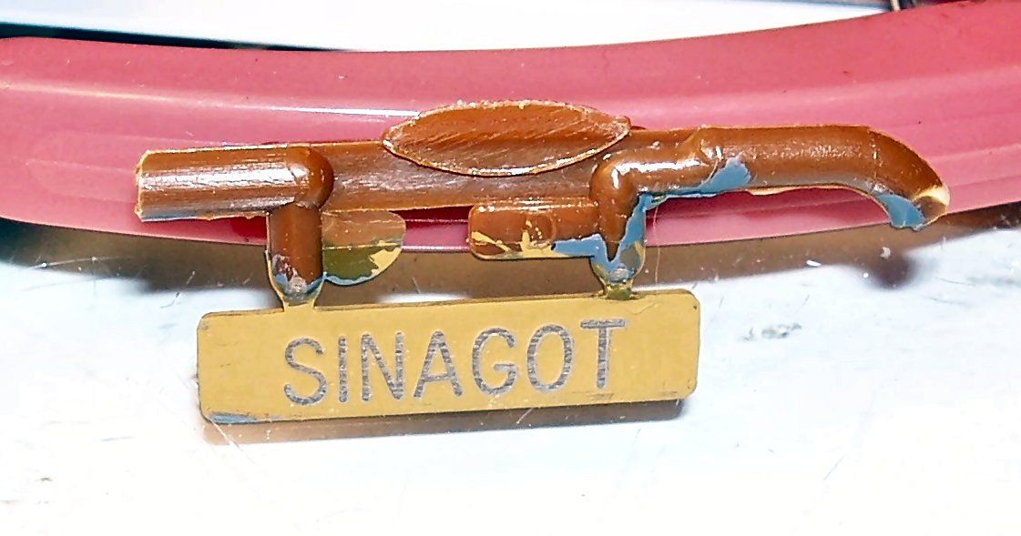
PART 14 A quick update. I sanded the faceplate to expose the original plastic color of the part, and it worked. I wish now that I had painted it with a lighter color, to make the contrast better, but you can clearly read the name. Here is a shot of the nameplate. I only had 320 grit sandpaper available, so you can see some scratches in the close-up, but not from viewing distance. I touched up the areas around the edges that also caught the sanding, and will go with this look.
-
My condolences!