thibaultron
-
Posts
2,644 -
Joined
-
Last visited
Content Type
Profiles
Forums
Gallery
Events
Everything posted by thibaultron
-
 Just ordered a set, thanks Chuck!
 -
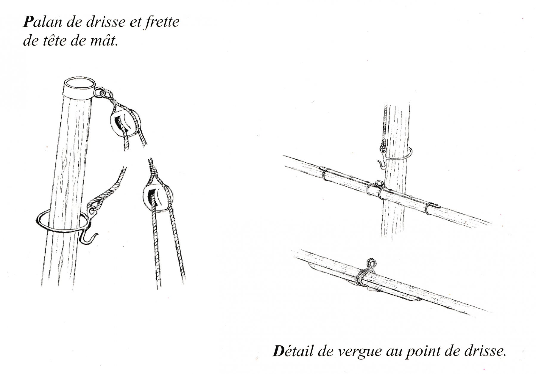
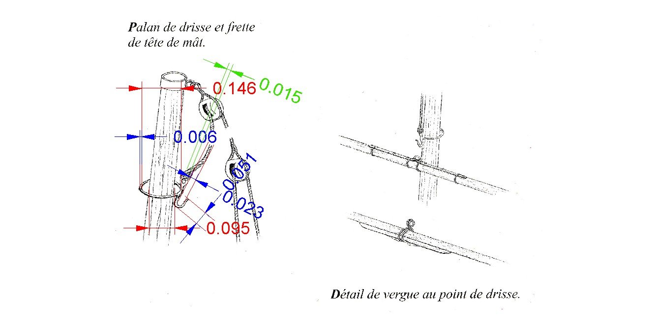
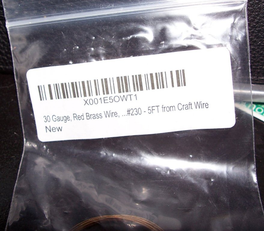
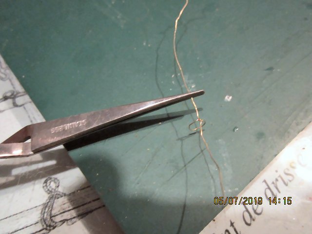
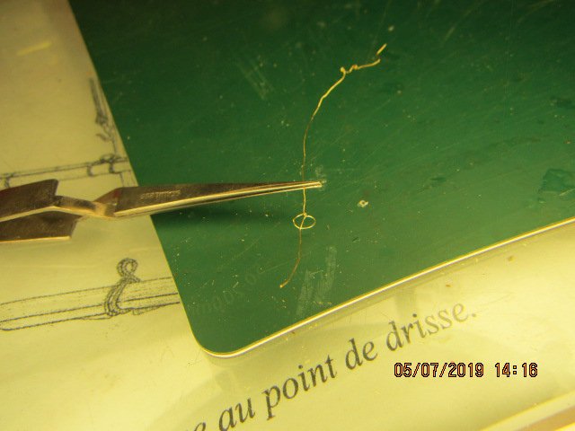
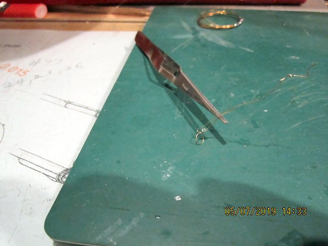
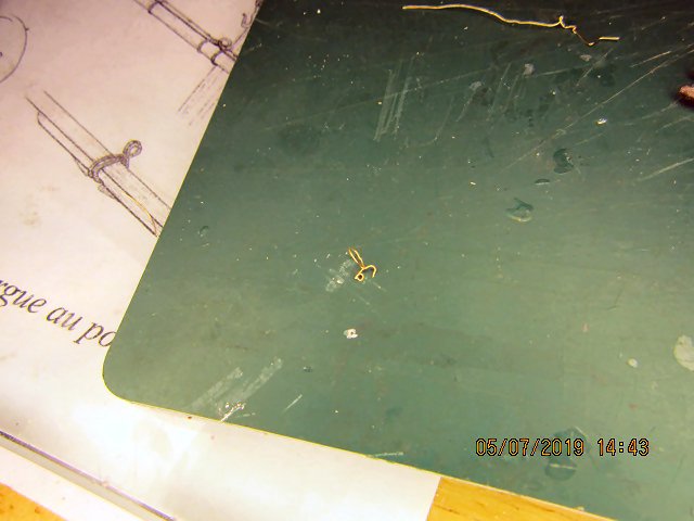
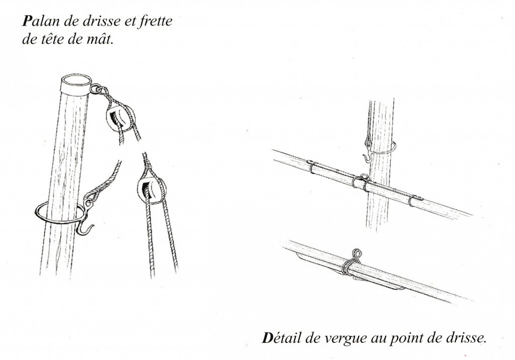
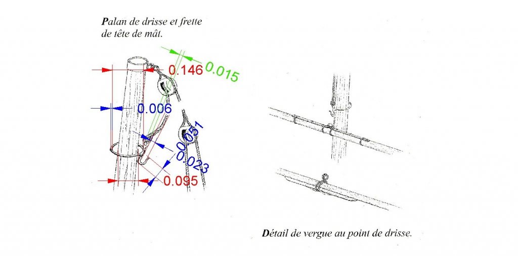
PART 11 I worked on the Hoist Ring today. This is the diagram I showed earlier, and the following one with dimensions. The critical dimensions are: Ring Diameter = 5/32” – 5/32 drill bit as form, initially (see below) Eye Diameter = 0.015” - #77 drill bit Hook Diameter = 0.023” - #73 drill bit This was just a practice/trial and error session. This is just as well, as the “new” used camera I was using was set on 640X480 resolution, as I discovered when editing the pictures! I bought 0.008” copper, dead soft brass, and half hard brass wire, to experiment with. The half hard is what I used, the copper was way too soft to hold a shape under handling. I skipped the Dead Soft, and found the Half Hard quite workable, and sufficiently sturdy. There will be no load on the ring as the spar will be glued to the mast. In this scale, 1/64th, I will not try to replicate the forged construction of the original. At first I tried wrapping the wire around the 5/32nd bit then folding the ends across each other, then vertical to form the hook and eye legs, forming a sharp corner, but no firm connection. This worked, but the ring did not hold its shape during further work. The two corners separated when the ring twisted. For the “final” version, I used a pair of needle nose pliers, with a stepped taper on one jaw and a flat mating surface on the other. For the area where the legs will be, I tied a simple knot by looping one leg back through the ring. After a bit of pulling and tightening of the knot, I got a firm joint at the legs. Next I used a pair of flat jawed needle nose pliers to clamp the ring in and stretched the legs to be at right angles to the ring. I then held a #77 drill bit on one jaw, on top of a leg and wrapped the wire around it, forming the eye. Then while also holding the #77 in place, I repeated this on the hook leg, using a #73 drill bit. This time I only wrapped it enough to form the bottom of the hook The assembly now looked like this. After playing with it a bit using pliers and tweezers to get everything in line, I cut the excess wire with a single bladed razor. Here is the final trial piece. You can see some kinks in the main ring. I was reusing the same piece of wire as I practiced, and it was distorted from prior attempts. For the final pieces I'll have to refine the eye, but I'm calling this trial Hoist Ring a success. When I make the finished parts, I’ll take a better sequence of pictures. I finally got the camera reset to take full resolution (14megapixel) shots, so the pictures will be better next time. It may be a few weeks before I can get back to the model. I’m about to start a month long 12 hours a day 6 days a week short term job.

-
Played a little with the wire for the hoist fittings. The .008" (0.2mm) is too soft. I was able to make a rough fitting, but it collapsed before I could finish. I'll try the brass wires today, with pictures this time. I may have to build a simple jig.
-
I would say a coat of epoxy or the old fashioned RC aircraft dope. I used the aircraft dope on the outside and inside of my RC Combat Warship models.
- 9 replies
-
- 1
-

-
- corel
- Chesapeake Bay Flattie
- (and 2 more)
-
Fantastic model!
-
Nice!
-
Table saw with a reasonable price
thibaultron replied to Clark's topic in Modeling tools and Workshop Equipment
How did the old Dremel saws stack up? -
I don't think you have to decorate both sides. I beleave the cross was only painted on the front of the sail.
-
Some do some don't, it would be nice if more did, but with the cheaper kits, it would add a chunk to the price.
-
Just a note on the sign. Never use RTV to mount the board like shown! The agent that sets normal RTV is an acidic compound, hence the vinegar smell, and will, over time, corrode that board. When building water tight boxes for my RC ships, I used aquarium grade RTV, which uses a non corrosive action. Even then I would mount the components with screws, and use the RTV only as a thin seal for the removable cover, and let the RTV set for a week or so, before closing the box.
- 133 replies
-
- 1
-
-
- alert class
- tugboat
- (and 1 more)
-
Frank, I think that the figure "8"s are not rope knots, but twisted rings. See the enlarged section of your photo. What is the address of this picture, I'd like to look at the site.

-
There is/was one on Ebay, this morning, at least.
-
Great job, and congrats on an unusual model!
-
I have two of these models, to be used on my railroad layout which will be a port scene. along with a Shell tanker. All are way small in scale, but should look OK alongside the layout. The layout is based on one I saw in a magazine, but slightly larger. The author toted it as a 2X10 design, to enter it in a contest. After CADing it out, it became apparent that the one he showed in the photos that he actually built was closer to 2.5X12! So I had to enlarge the design. The ships in his pictures look good in the scenes. Trying yo fit even a single HO scale freighter in a reasonable sized layout would be difficult, let alone three or four. They have to be low models, also, so you can reach over them to uncouple the cars, or re-rail them.
- 7 replies
-
- 4
-
-
- northsea fishing trawler
- revell
- (and 1 more)
-
Shop Safety and Oops Repairs
thibaultron replied to BETAQDAVE's topic in Metal Work, Soldering and Metal Fittings
The more I get to know people, the more I like my cat! -
Shop Safety and Oops Repairs
thibaultron replied to BETAQDAVE's topic in Metal Work, Soldering and Metal Fittings
Hope it heals well. You might want to have that looked at, you may need a stitch or two. -
Welcome to the forum, and thank you for the service you provided!
-
My Spray Booth Construction
thibaultron replied to thibaultron's topic in Modeling tools and Workshop Equipment
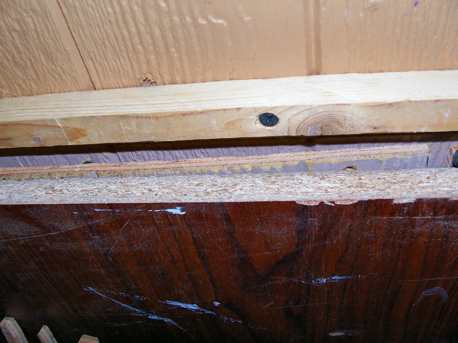
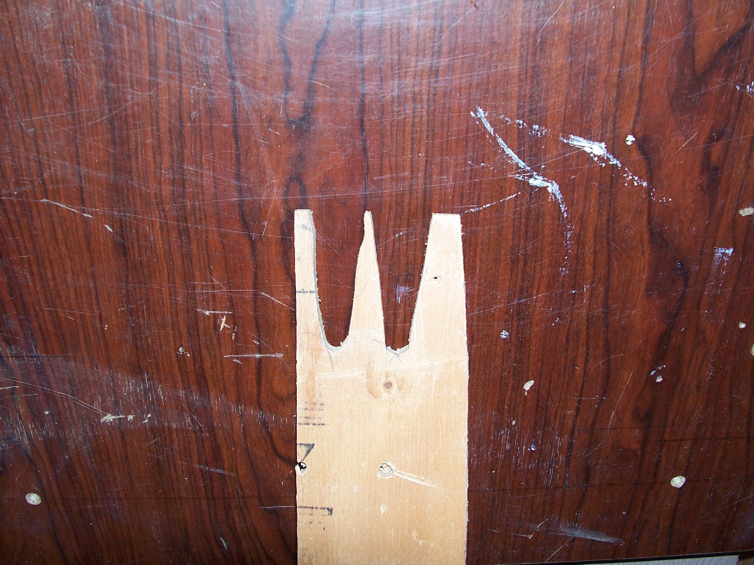
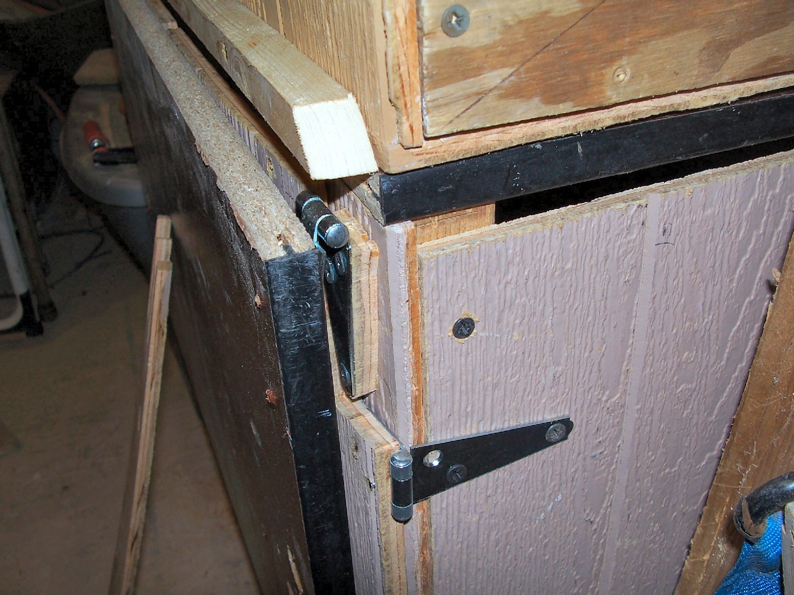
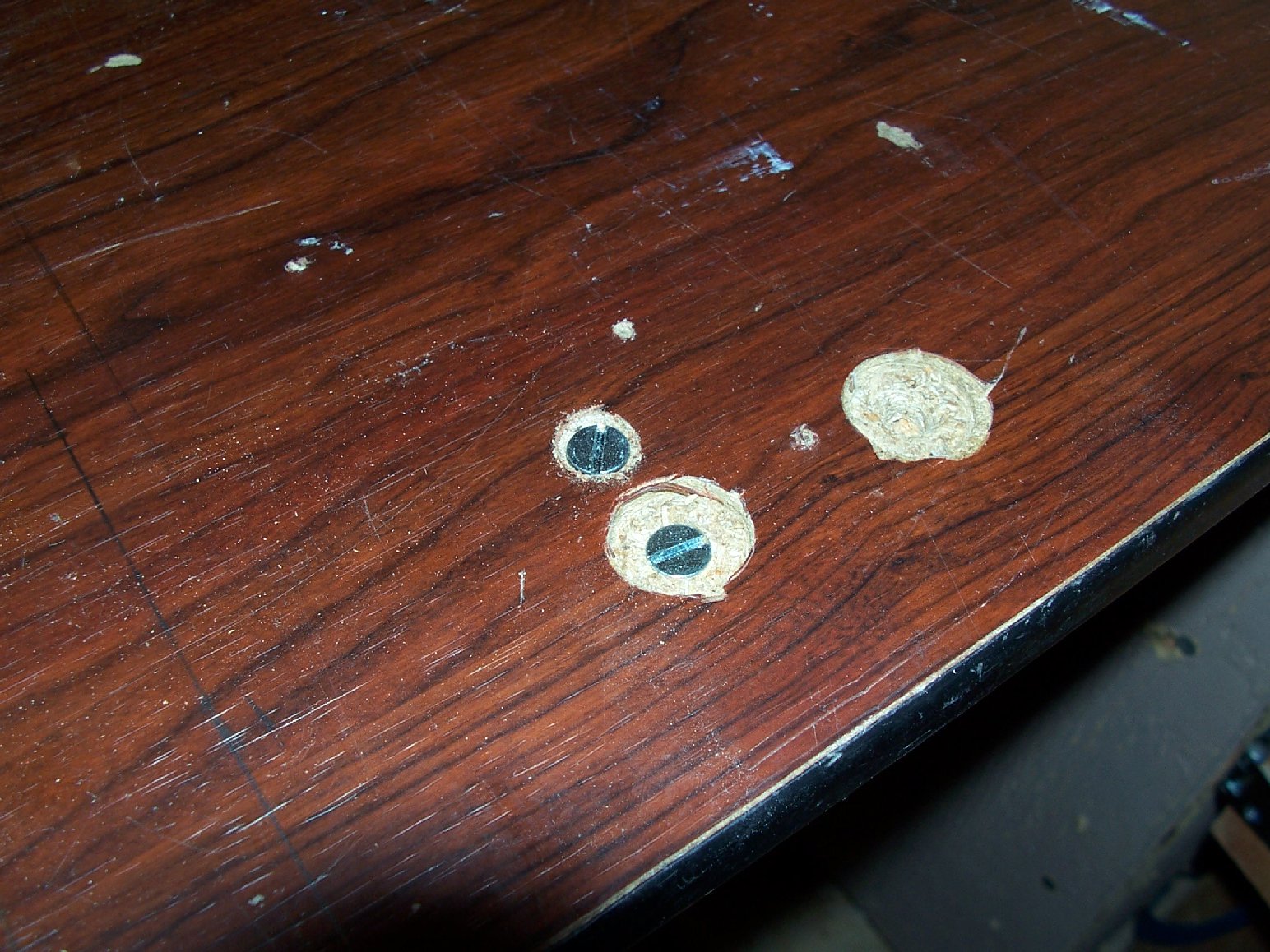
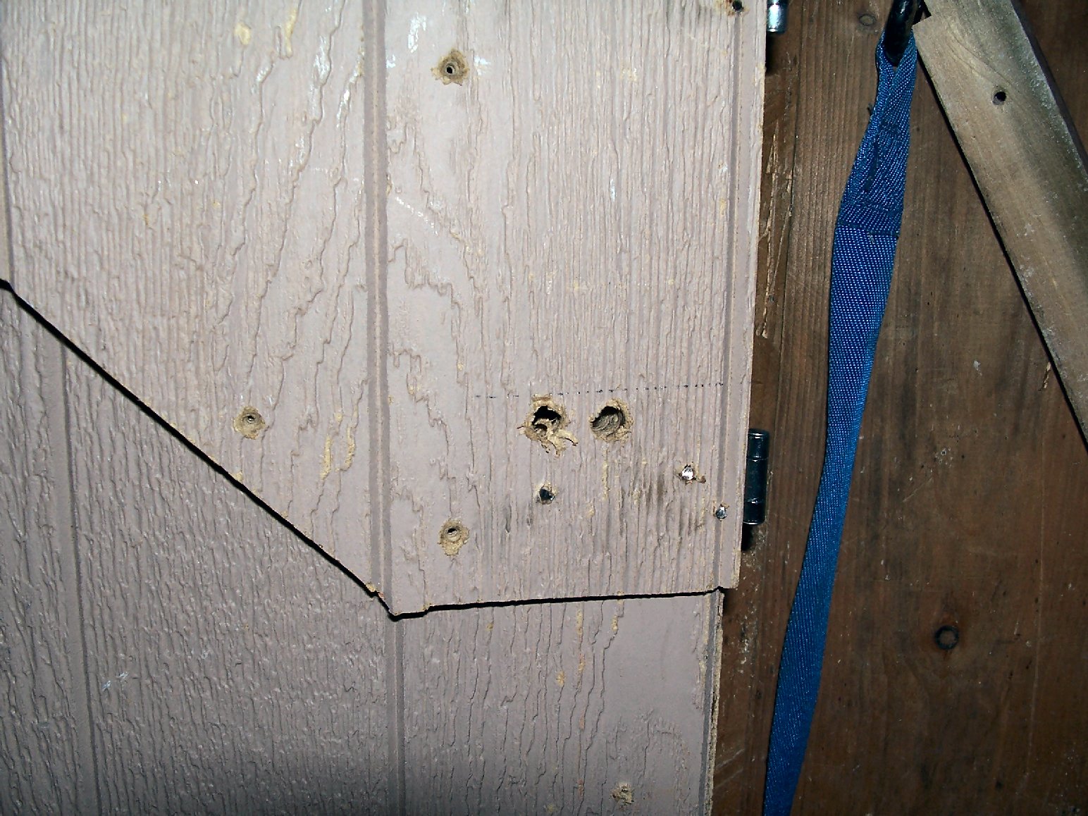
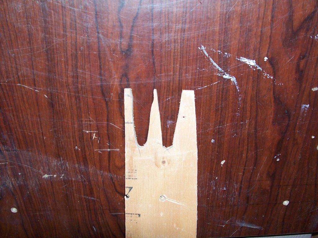
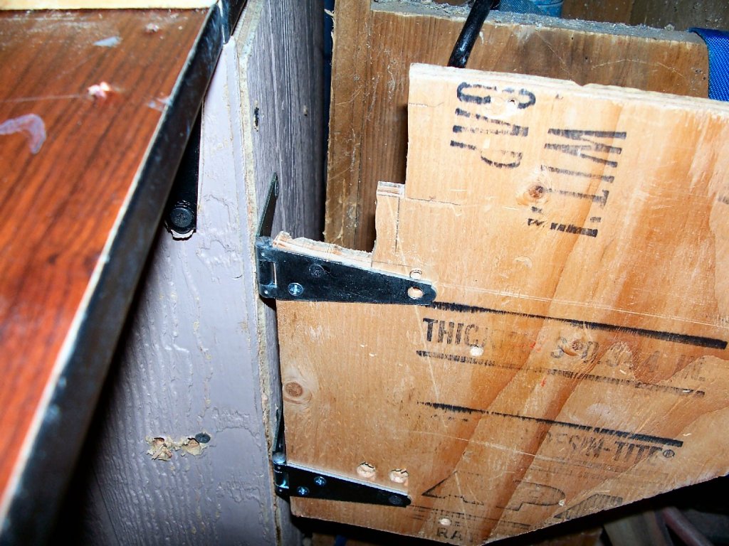
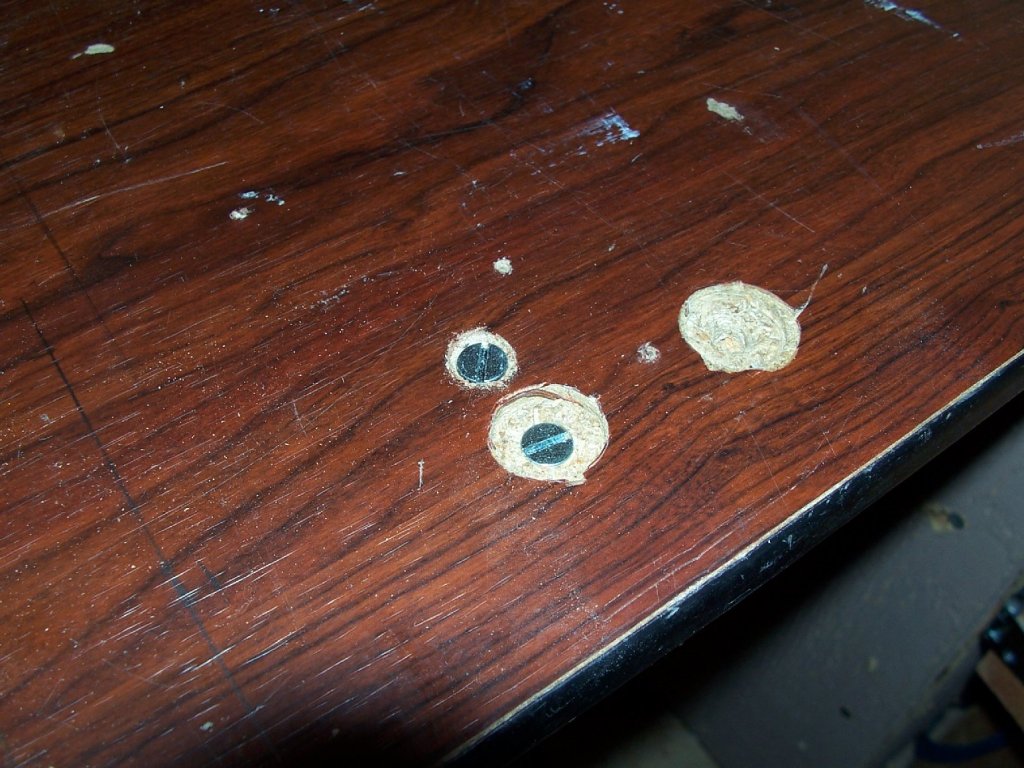
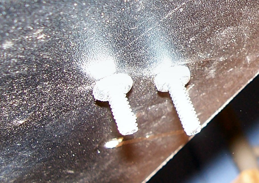
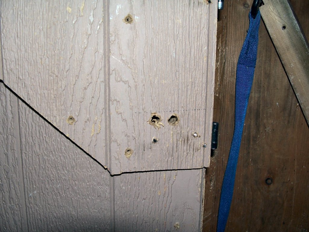
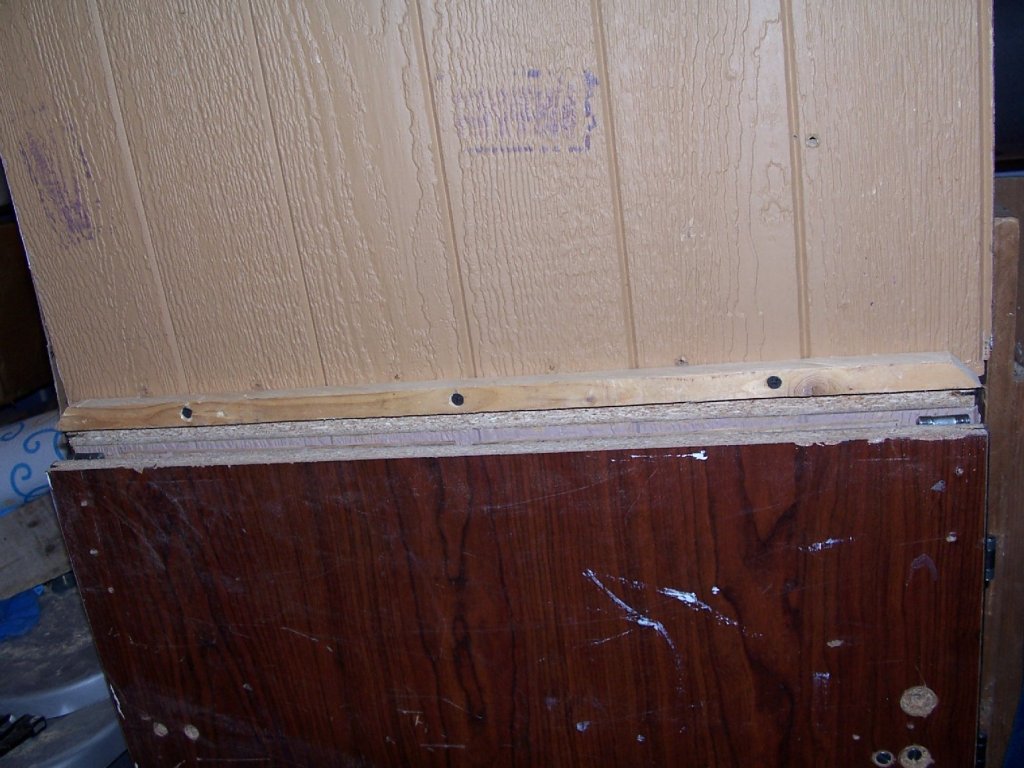
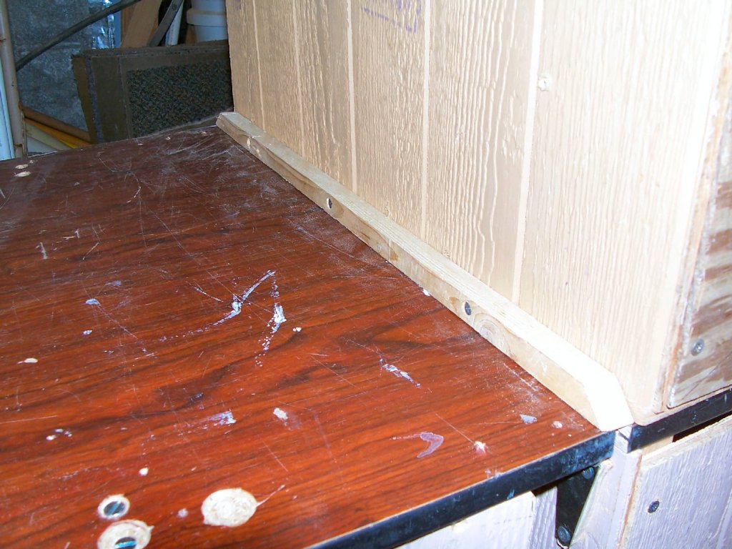
Part 13 I finished installing the drop leaf today. I discovered that one of the supports was warped, and there was no way just adding a washer or two behind the hinge was going to let the leaf swing down fully. This shot shows the warped leaf, on the right, if you look closely. This is after I added the plywood washers (see below). I cut two hinge leg shaped washers from the last scrap piece of the plywood I built the booth out of. This shot is of the piece, after the washers were cut out. I’d already installed them before I thought to bring the camera out. I drilled out three holes in the washer. To match those holes in the hinge leg. I drilled these the same size as those in the hinge, as in a metal washer. Then I removed the hinge screws and installed the ply washers between the hinge and the side of the booth stand. You can see it in the middle upper of this picture. With the thick washer in place I had to trim the corner of the supports a bit more, to clear the bottom of the hinge leg. To capture the supports when the leaf is up, and prevent them from being accidentally knocked back to the folded position, I put in two #10-24 flat head screws into the table. A number 6 or 8 would have been sufficient, but I reused an existing hole, so had to go with the #10s. I counter sunk the table for the screws, and secured them underneath with a nut. The support is swung out and placed with the screws on either side of it, preventing it from being knocked in either direction. The leaf lifts up high enough for the support to clear the screws when positioning the support. The picture below is way out of focus, but you can make out the screws and nuts. I drilled a 3/8” hole in the folded in supports and the side of the stand, to clear the screws when the leaf is folded down. Adding the ply washers, of course, moved the edge of the table away from the booth by 3/8”. To keep little “things” from rolling down that slot, I added a ¾” square batten to the side of the booth, that seals the gap, with the leaf up. Adding it to the table would have been better, but there was not enough “meat” at the edge of the leaf to hold screws. I would have had to go with a wider batten, to attach it to the table. I chamfered the ends of the batten, so that there was not a sharp corner to hit. I still have to replace various hinge screws with #8-32 flat head machine screws, but I don’t have any, at the moment.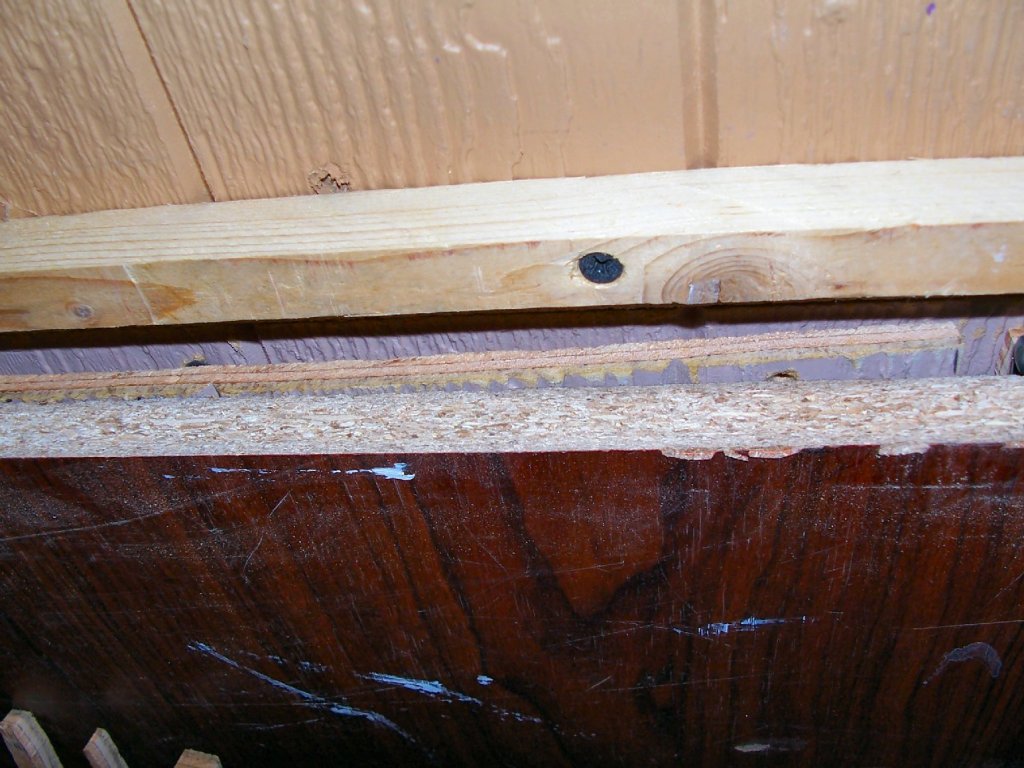

-
Ordered some .008' copper wire, as well as .010 half hard and dead soft brass wire to make the hoist rings from. Here is a dimensioned drawing from the book. I hope that at least one of the wires will be strong enough to hold up after i make the fitting. It will not have to support the yard, That will be glued to the mast, as per the kit design, but it will have to withstand my fumble fingered installation! I estimated the sizes by measuring the actual diameter of the masts at the ring height, and used that as a basis for the other ones. CAD is great! The final diameters of the ring may be slightly larger than in the drawing, as the base of the masts are 0.115", and the ring should be able to rest on the deck, I would think. The drawing is quite busy, but it has all the dimensions I need.
-
Found this link on home 3D printing. he has 3 videos in the play list.
- 133 replies
-
- 1
-
-
- alert class
- tugboat
- (and 1 more)
-
Try water in the bottle instead of paint. Water is what they use at Badger to test every airbrush, before shipping. If it will not even spray water, there is something very wrong with it.
- 133 replies
-
- 4
-
-
- alert class
- tugboat
- (and 1 more)
-
I understand Badger also has great customer service, give them a call.
- 133 replies
-
- 2
-
-
- alert class
- tugboat
- (and 1 more)