Louie da fly
-
Posts
7,991 -
Joined
-
Last visited
Content Type
Profiles
Forums
Gallery
Events
Everything posted by Louie da fly
-
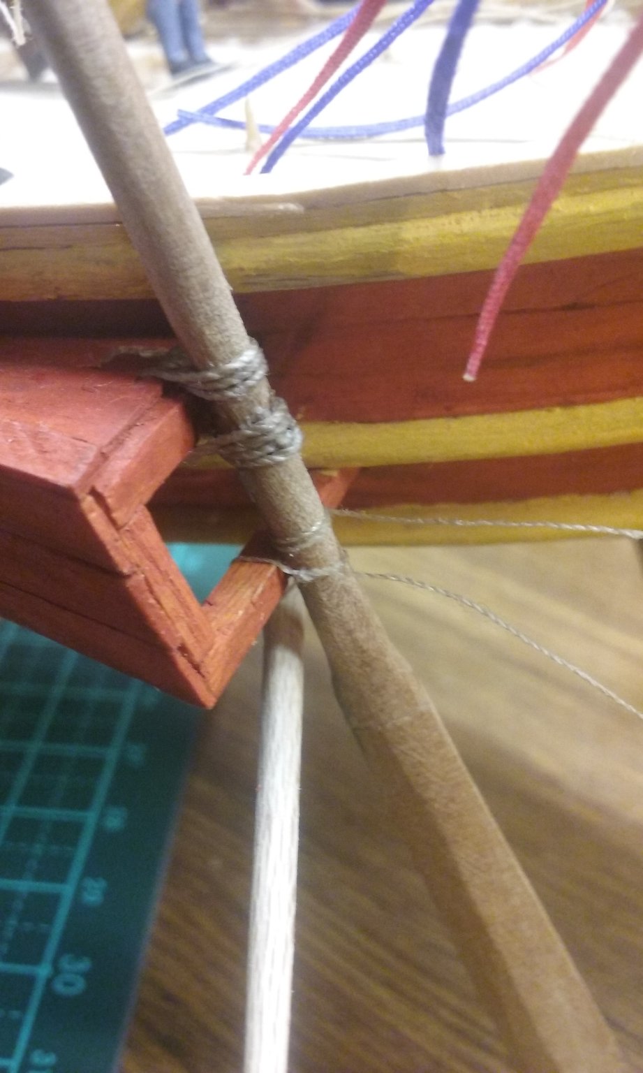
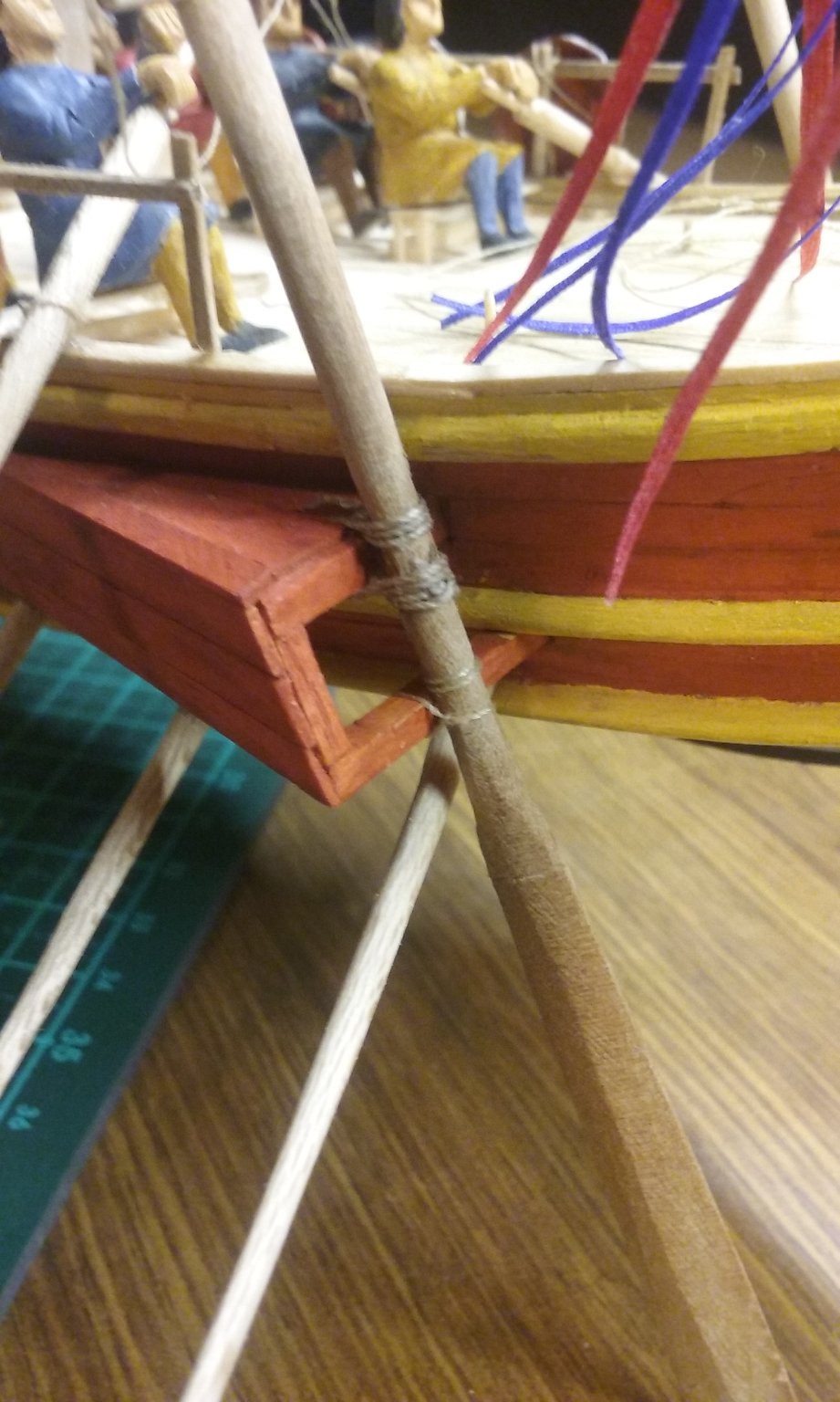
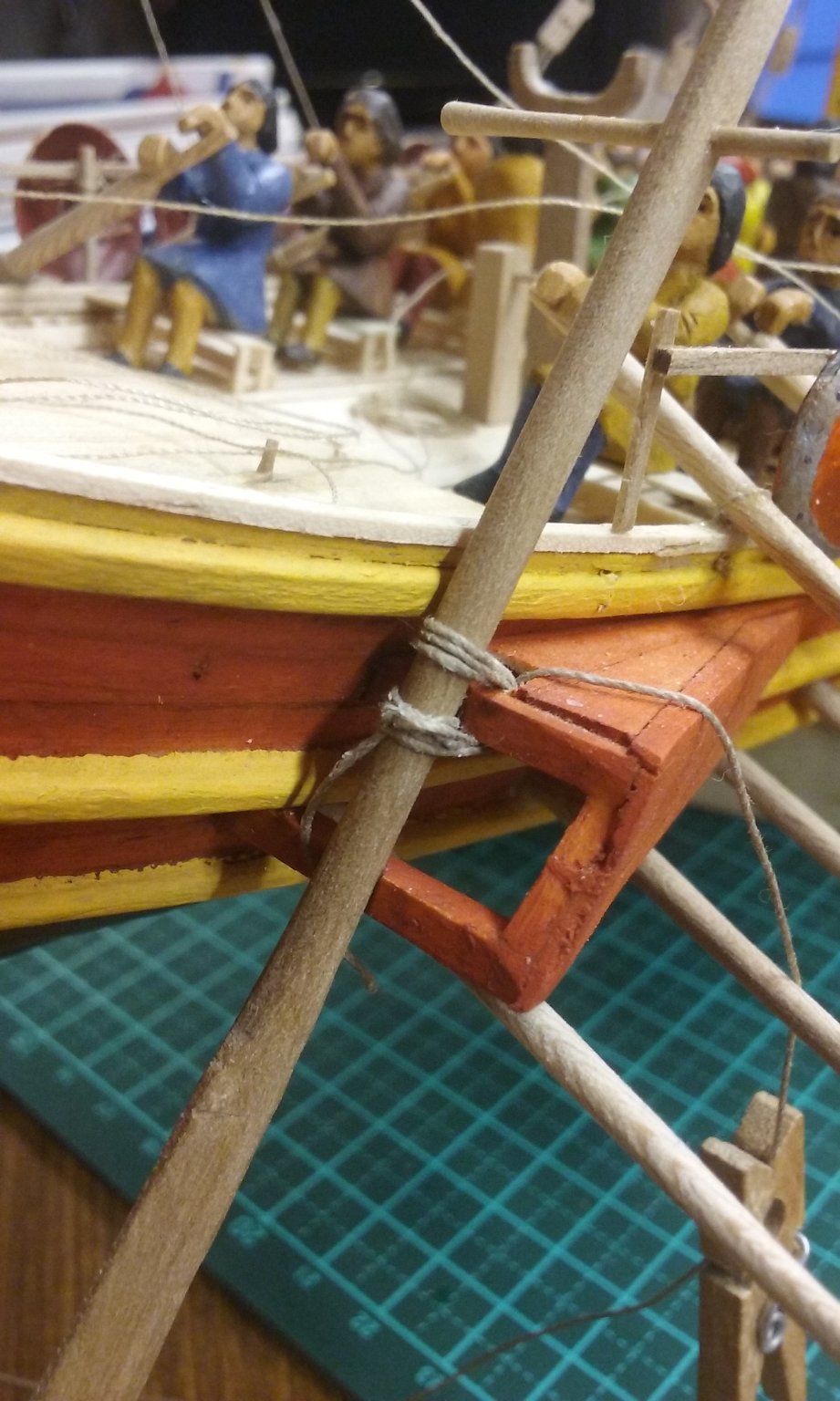
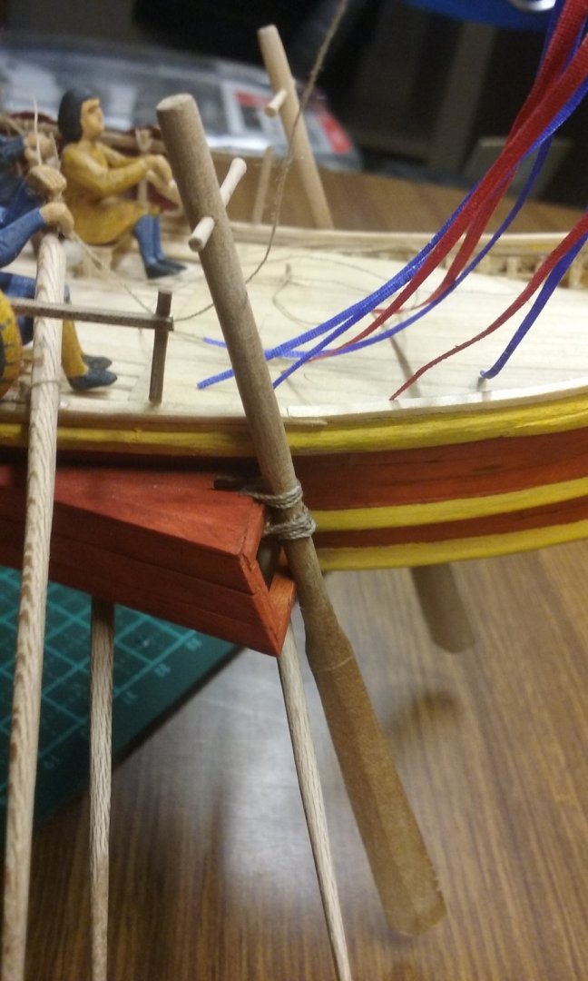
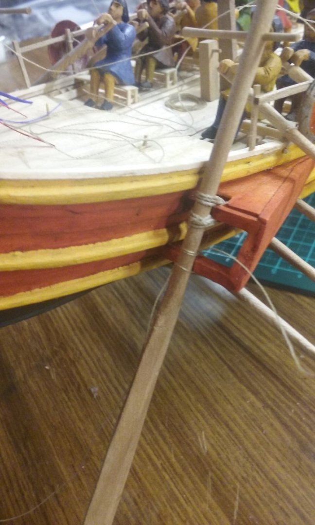
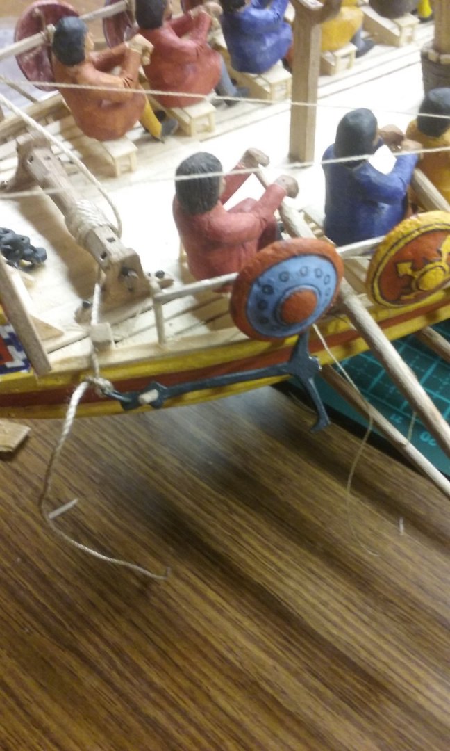
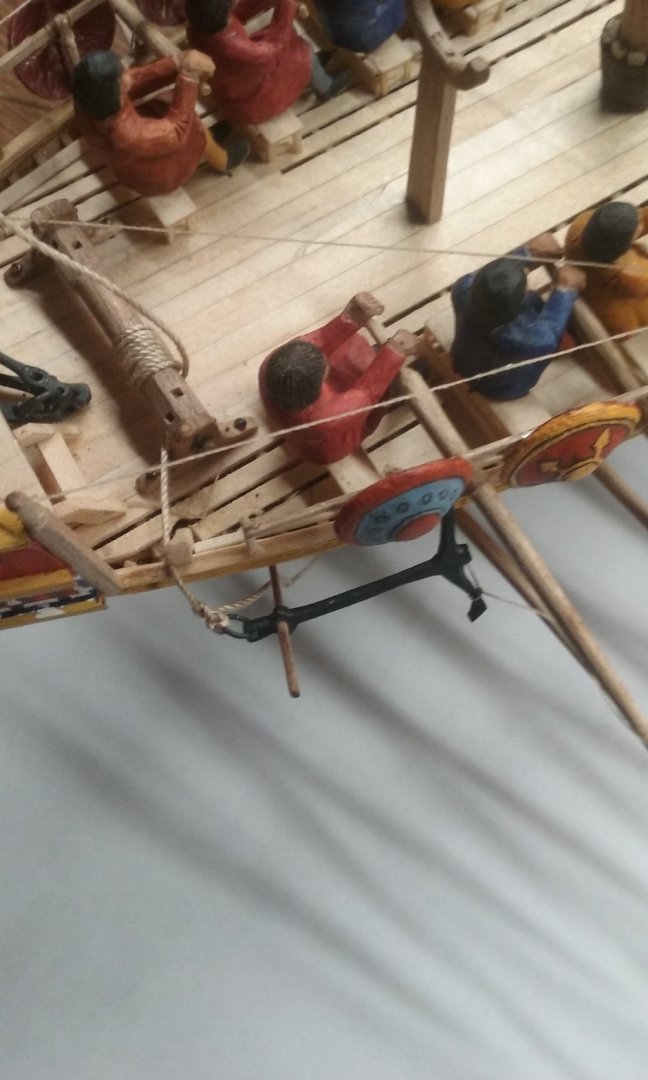
 And on to the lashings for the side rudders. The diagrams of lashings in the TAMU paper I mentioned on the previous page weren't much help, so I worked up something of my own. Remembering back to my days as a Sea Scout at the age of 14 I remembered a lashing we'd used. But first I had to re-teach myself how to do a clove hitch, something I hadn't tried for 57 years, and even back then I'm not sure I really mastered it. Took me two or three goes with the instructions in front of me, then maybe half a dozen tries without. And I think now I can do a clove hitch from here on in - something I think is going to be very useful in future models involving ratlines(!). The clove hitch starts the lashing: Then round and round: This is a sort of universal joint made from rope. It allows the rudder shaft to pivot left and right for steering under the influence of the tiller, just as in a stern rudder. And it can also swing upwards around the beam so the rudder lifts out of the water - either when only one rudder is in use, or to enable the dromon to be pulled up onto the beach stern-first. Then for the lower lashing - this one is made of lighter rope. According to the TAMU paper on the previous page of this log, if the rudder hits a submerged obstruction, instead of the rudder shaft being shattered the rope will break allowing the rudder to swing up out of the way. Before beaching the ship this lower lashing is untied. That's all for now . . .
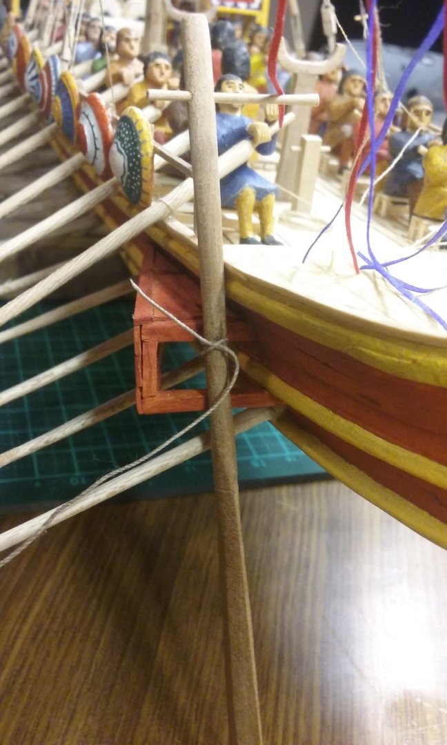


-
Congratulations, Hellmuht! You've done a beautiful job of this model; a combination of thorough research, inspired guesswork when the information wasn't available, and superb craftsmanship.
- 158 replies
-
- 2
-

-

-
- byblos ship
- Egyptian
- (and 1 more)
-
Glad you liked them, Christos. Probably the best website for these is https://zaherkammoun.com/2017/01/06/des-mosaiques-de-sousse/
-
Roter Löwe 1597 by Ondras71
Louie da fly replied to Ondras71's topic in - Build logs for subjects built 1501 - 1750
A real pleasure to watch your progress. Beautiful work. -
Thanks for the idea, Carl. But I feel I'm committed now, and I really don't want to go back. I've got a solution that works now - that's good enough, I think.
-
Thanks for the likes, everyone. and for the flattering comments. Possibly - were you thinking of supporting it from the lateen yard? Without something to support the block I can't see how you'd do it that way when the mast and yard have been lowered. Or were you suggesting that the block's tackle should be belayed to something lower down, such as the pavesade (railing to support the shields)? I'm a total duffer when it comes to this sort of thing - always have been. For me, learning how rigging works is like driving nails (blunt ones) into my brain.
-
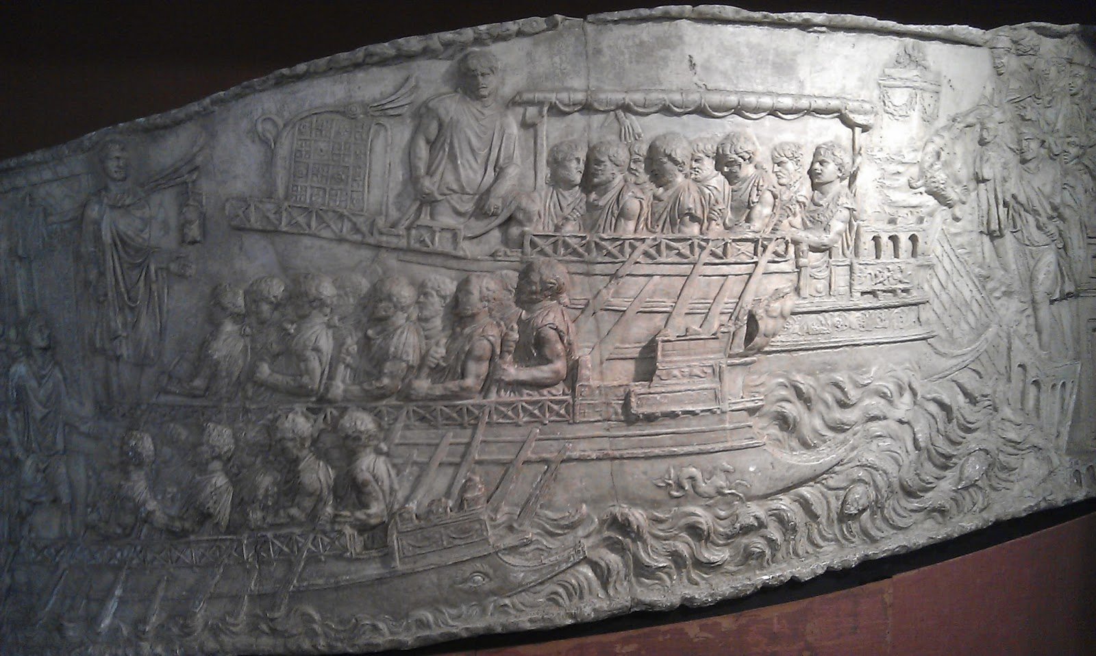
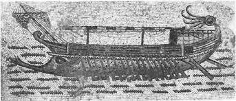
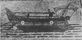
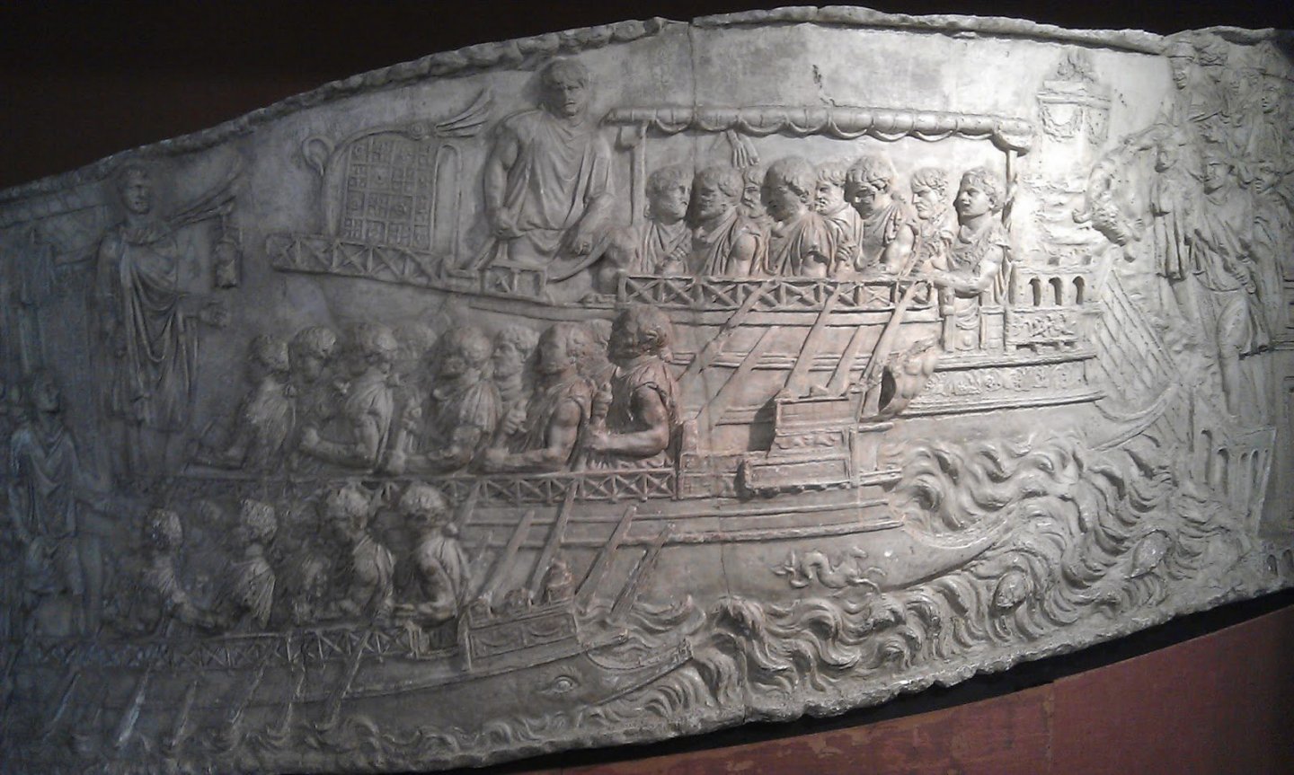
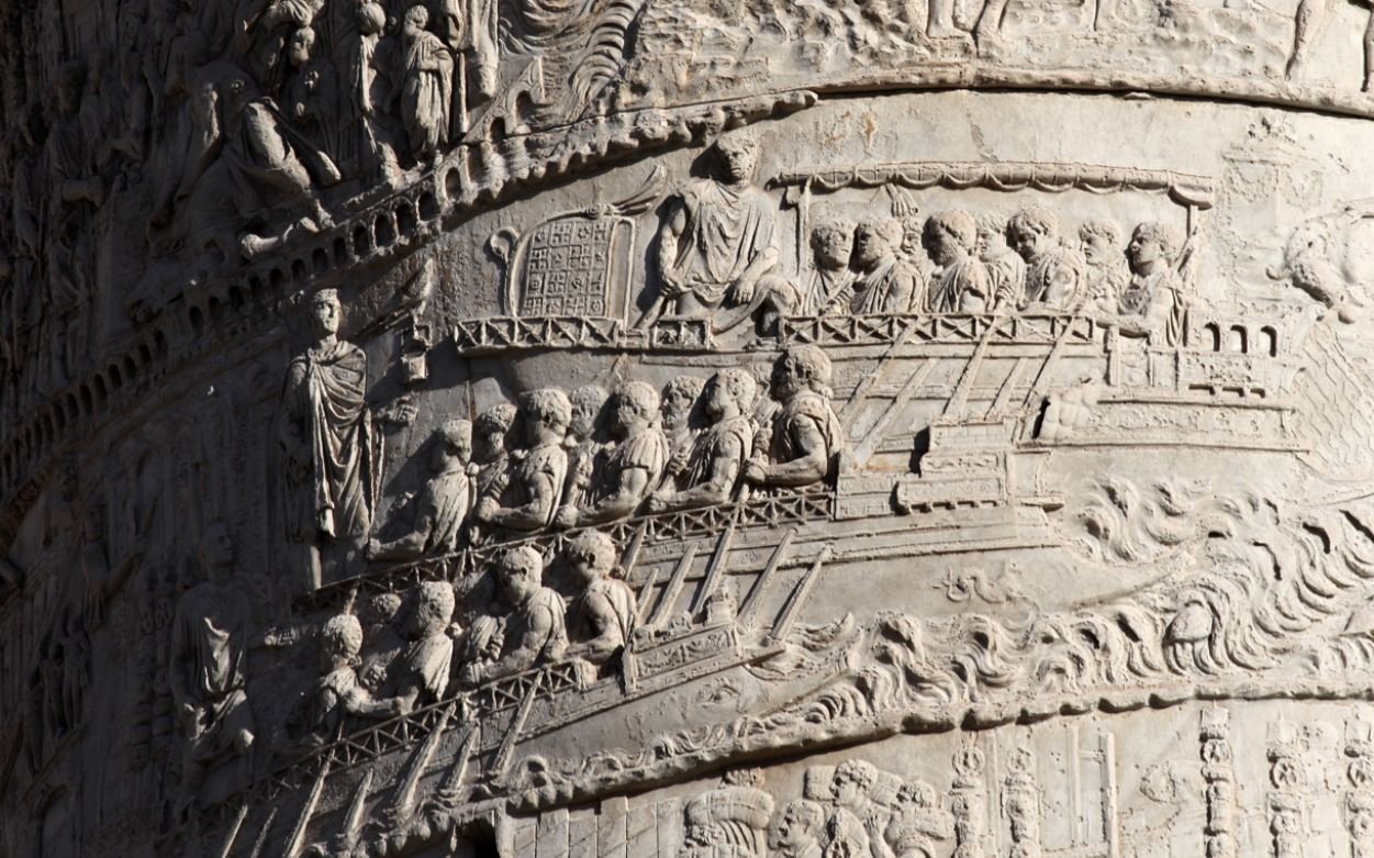
Looking very good, Christos! She's almost ready to go. I thought you might like a few contemporary representations of vessels with dropped masts, showing the ιστοδόκη on each. 3rd century galley mosaic, Themetra, Tunisia Themetra baths Tunisia Themetra baths Tunisia Hellenic ship, mosaic (ca 1st century BCE-CE). This one doesn't show the ιστοδόκη, but it looks like they're dropping the mast. Trajan's column c. 114 C.E. Trajan's column c. 114 C.E.
.jpg.112c305471aefd007a1c8f3d760bcdd8.jpg)
-
Those guys were a lot tougher than we are today - no footropes, just shimmy up the yard - no problem! (I'm scared of heights anyway, so I'd be no use whatsoever.) Here's another picture of the same thing, by the Portuguese painter João José Vaz (1859 - 1931)
-
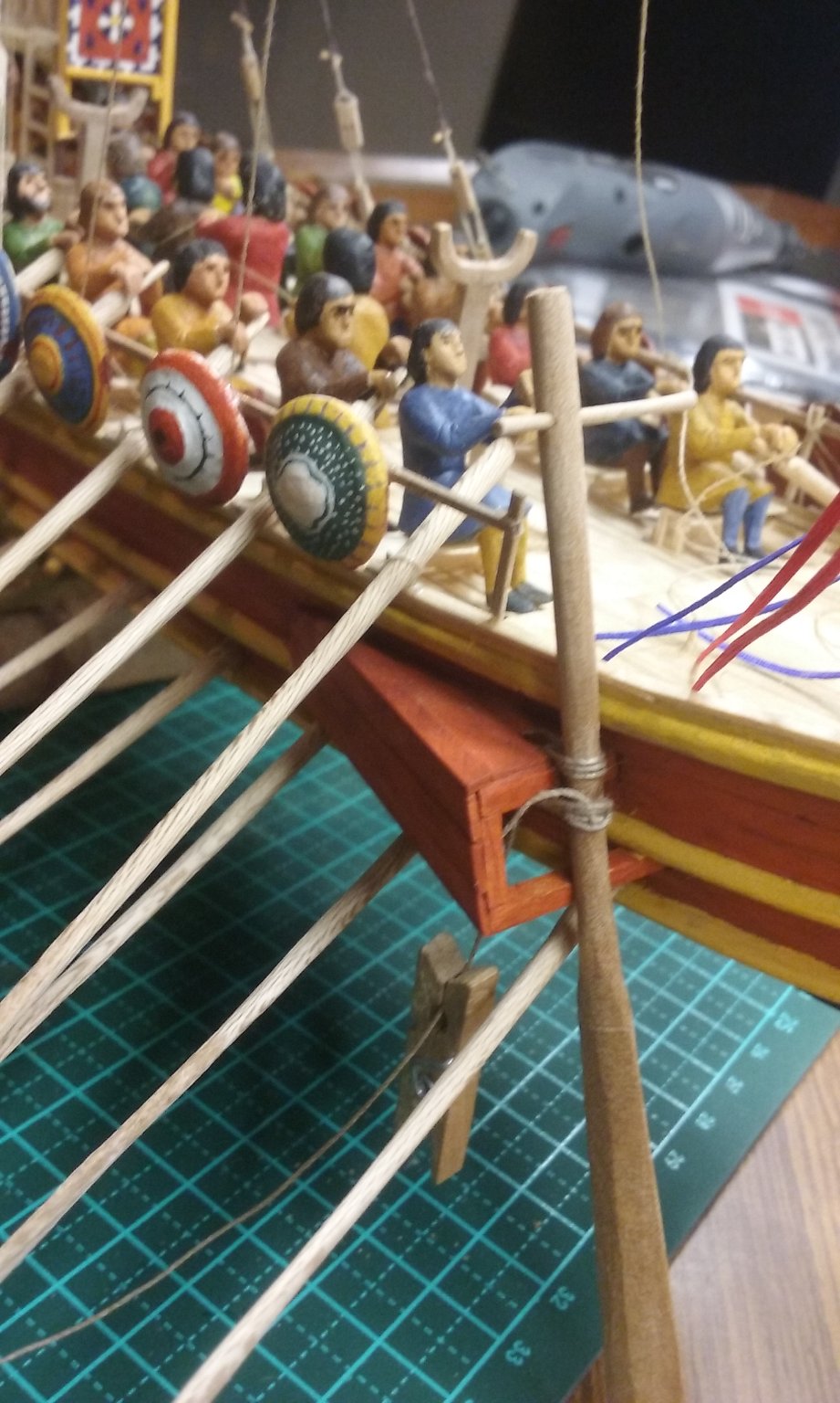
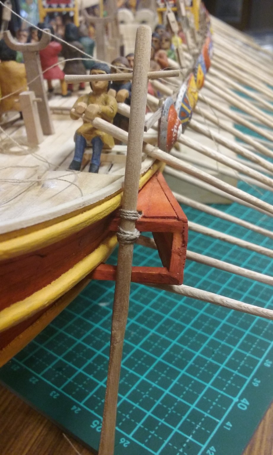
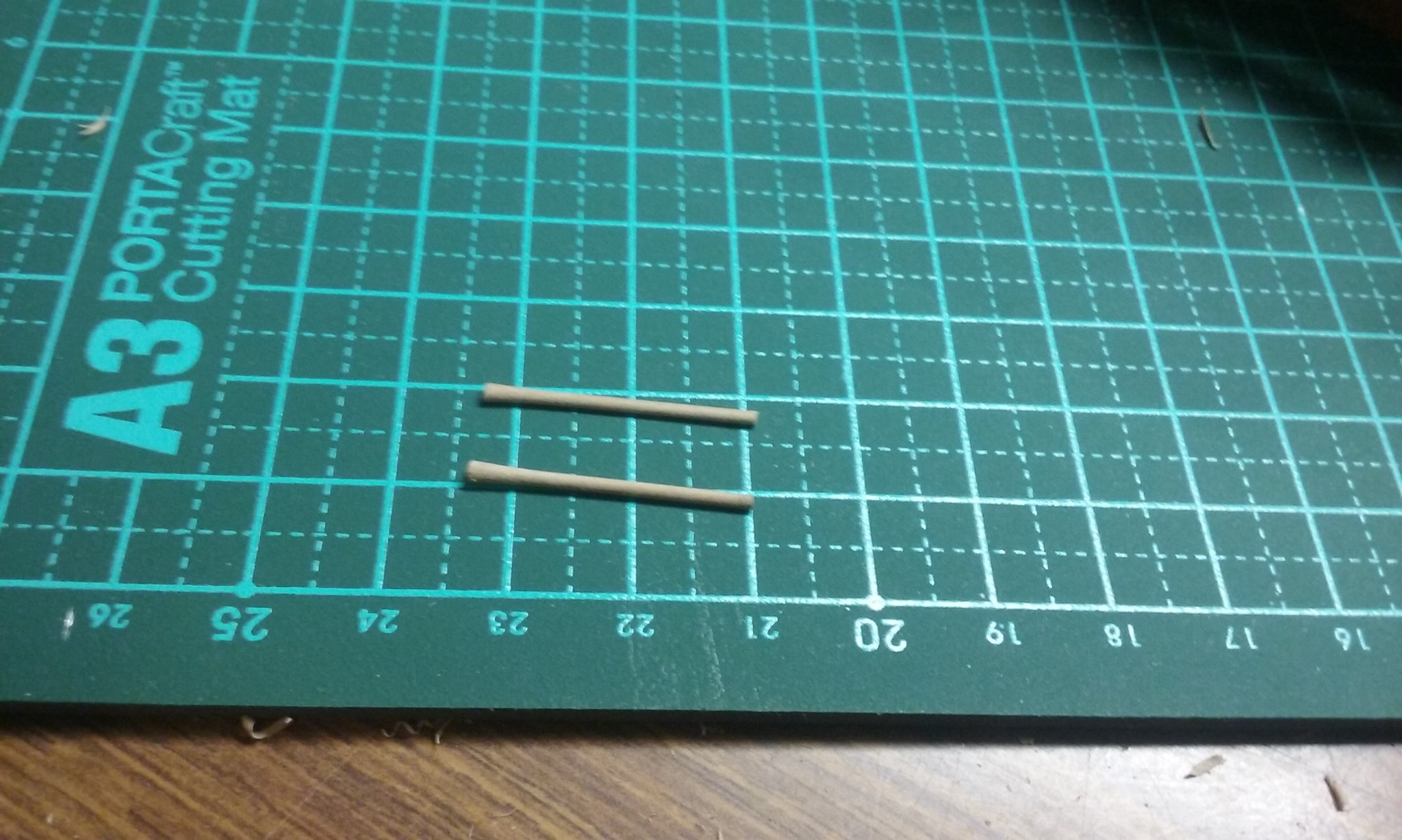
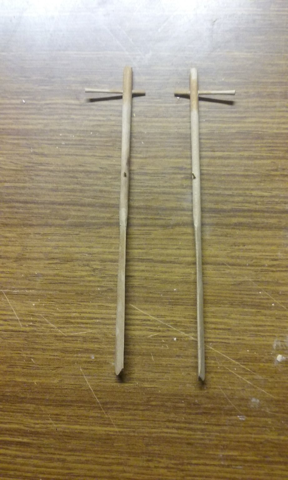
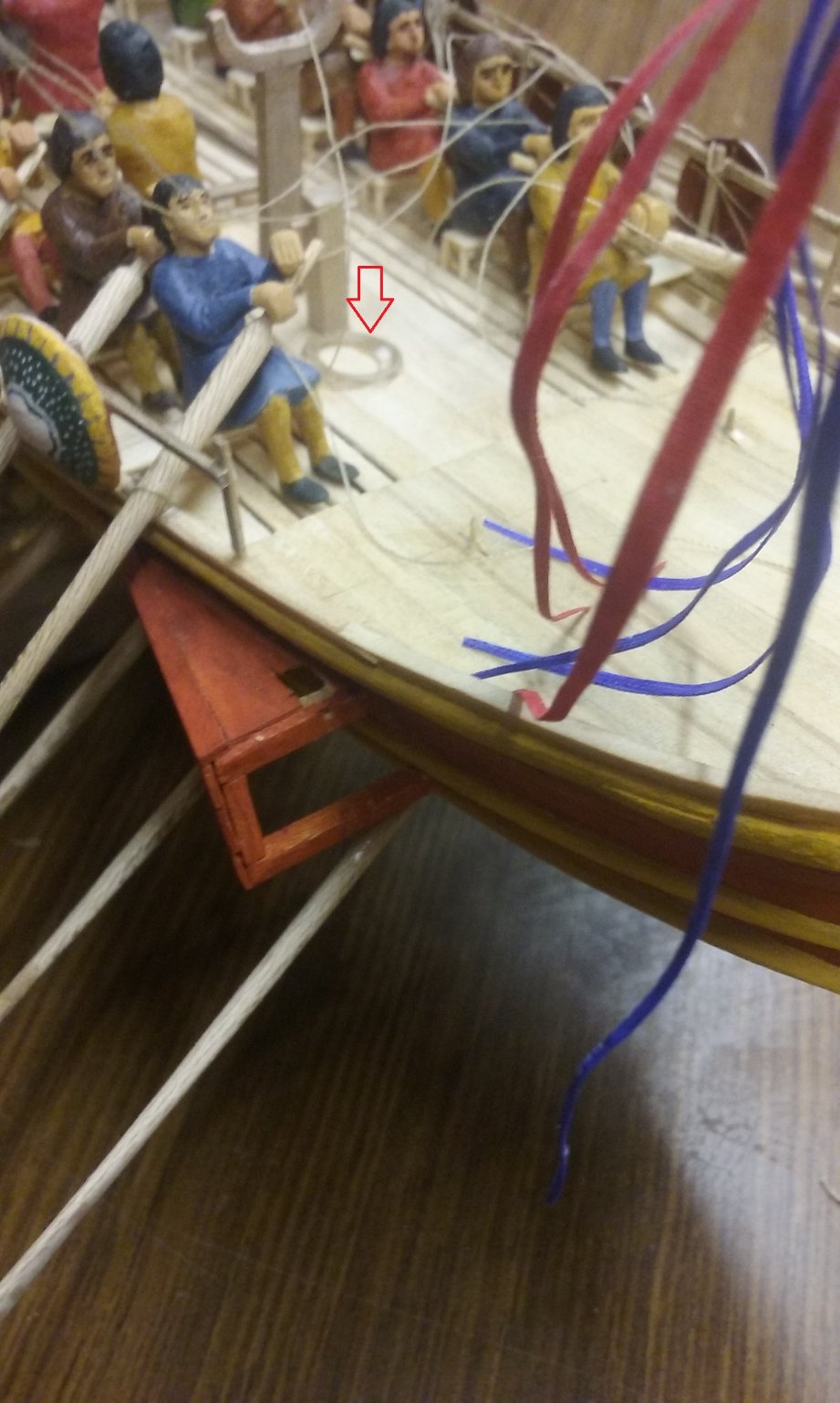
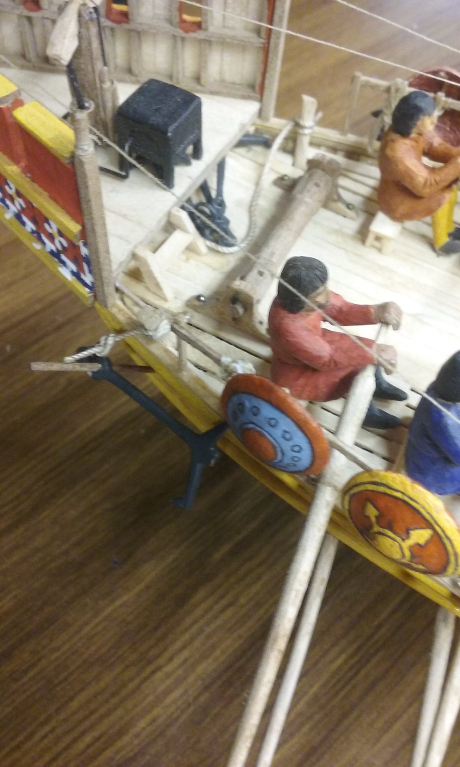
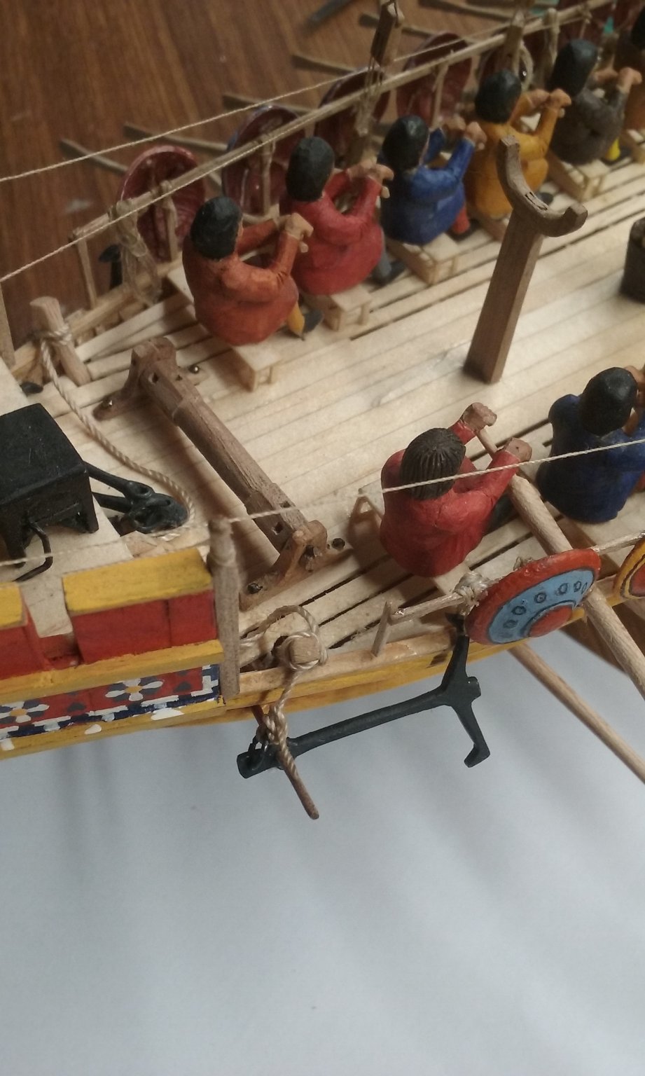
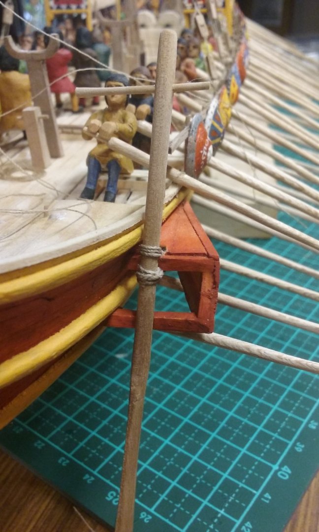
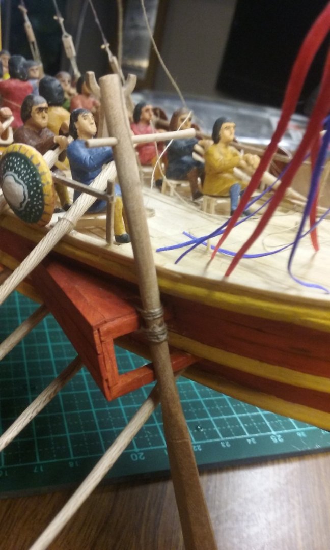
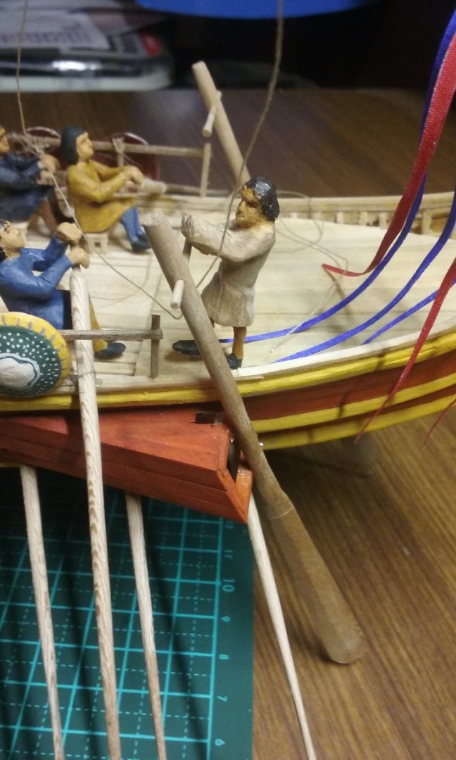
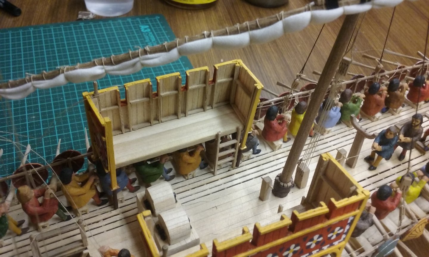
I've made and installed the tillers for the side rudders (steering oars) and put the rudders in place. I discovered I'd slightly miscalculated the position and angle of the holes for the brass pins mentioned above. The tillers were too high and instead of facing directly across the ship they were angled a little aft. So I drilled new holes in the rudder shafts - fortunately the old holes are hidden by the shafts themselves when the rudders are in place. I have yet to add the rope lashings that supposedly hold the rudders in place, finish the steersman I've already made (he's just standing there loose fitted at the moment), and carve another steersman for the other rudder. I've been tidying up the free ends of the rigging (the bosun will be pleased) - adding coils to the ends of the loose ropes, particularly for the after yard where the tacks and vangs aren't yet ready to be pulled tight (and shortening the ropes - so the coils take the place of the bit I've cut off). That way they're not all over the decks. I'm still thinking about the free end of the halyard tackle the crewmen are pulling on to haul up the yard. By rights, there should be a lot of it - if you take into account all the rope that runs between the blocks of the tackle. But I'm thinking of cheating and just cutting it shorter - otherwise it's just going to mess up the deck. And I forgot earlier to post the fact that I've added ladders to access the side castles. I had to put them at the after end of the castles so they didn't get in the way of the oarsmen getting to their benches - they can just get in through the side of the castle, (except the man right in line with the ladder, who can get to his own bench by climbing over the back of it).
-
I haven't been looking at this build for a while. Your progress is very impressive, and the boat just keeps getting more and more beautiful. And I think I'll steal your idea for the sail!
- 72 replies
-
- 2
-
-
- fishing boat
- Barco Catalan
- (and 1 more)
-
Just a note with the hearts - make the hole before you cut the block out. That way you can avoid the problem of splitting the block when you drill the hole (don't ask me how I know!) The shoulder pieces would be a good idea for keeping everything in place, but given the purpose of your model it's not vitally necessary. It's down to how good a model you want to make. I can see the lure of the Dark Side has gotten to you . . . By the way, I do like the toggle through the side of the ship that you've used to terminate the lower end of the shroud.
-
Very interesting video. It looks like a lot of fun. I wasn't sure about the reef points - how far back reef points go - I thought they didn't come in until later but on investigation I found this picture which is supposed to be late 13th century but judging by the armour (something I do know about) it dates to about the middle of the 14th - and it does have reef points. But in fact the longship from Skamstrup in my post above also has them, so you the problem I was concerned about didn't really exist. (Nonetheless, I think it was worth going to the trouble of checking.)
- 179 replies
-
- 5
-
-
- longship
- Helga Holm
- (and 1 more)
-
That's very interesting. I hadn't known about the "light" trieres at Salamis. I'm enjoying following your historical research.
-
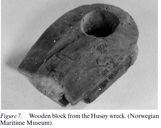
"Butterfly cleat" sounds good. But they've only been found on Viking ships and yours is several hundred years later. I'd be going with hearts myself, as attested by this one from about 1390-1400. According to the report "A number of loose rigging items were found, including six complete or partial blocks and two possible deadeye fragments . . .The largest block has seven holes but the others have only one or two" It appears the report doesn't distinguish between hearts and conventional blocks with sheaves, but the one below at least is definitely a heart, and possibly the others are too. Looks like one end has been cut off?
-
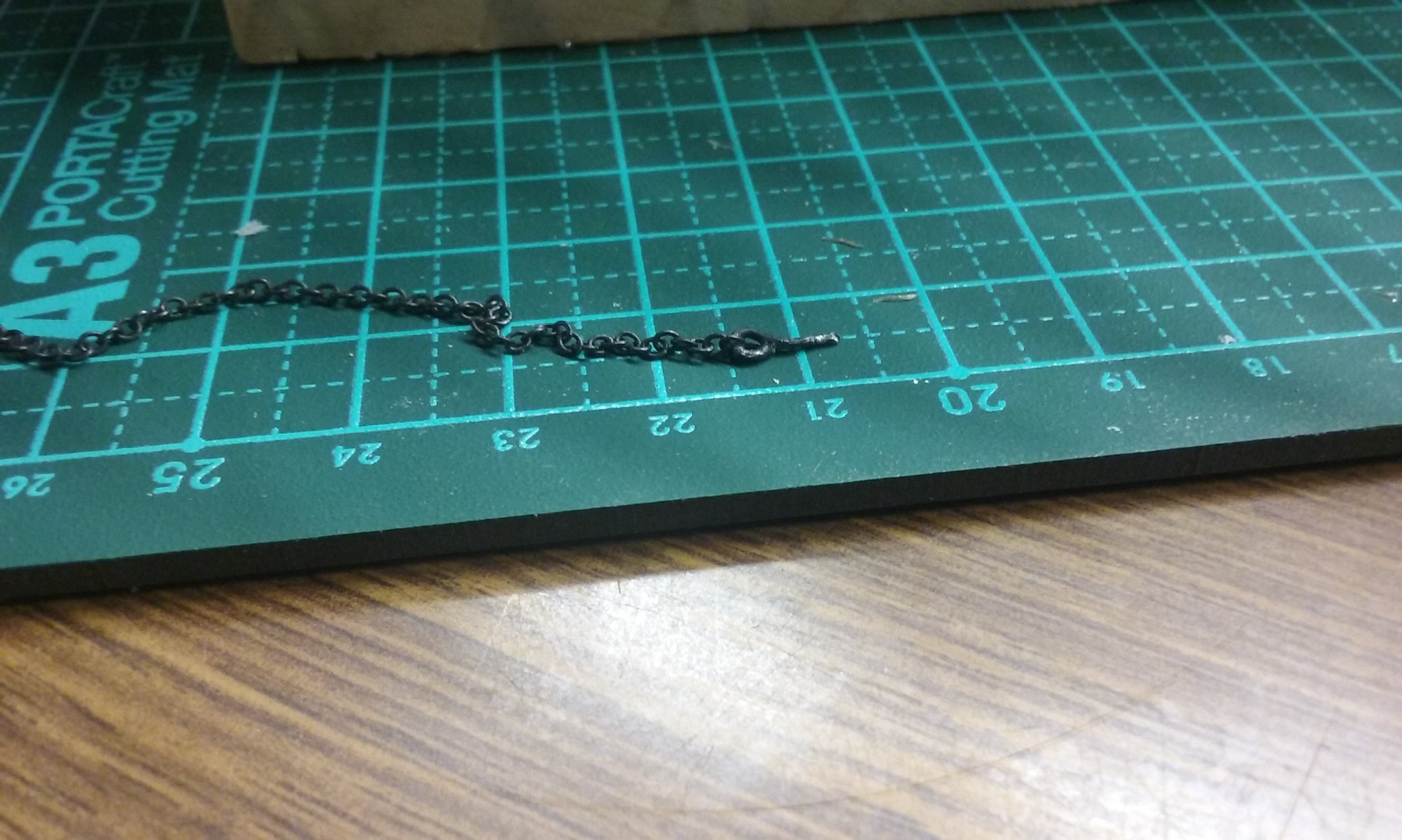
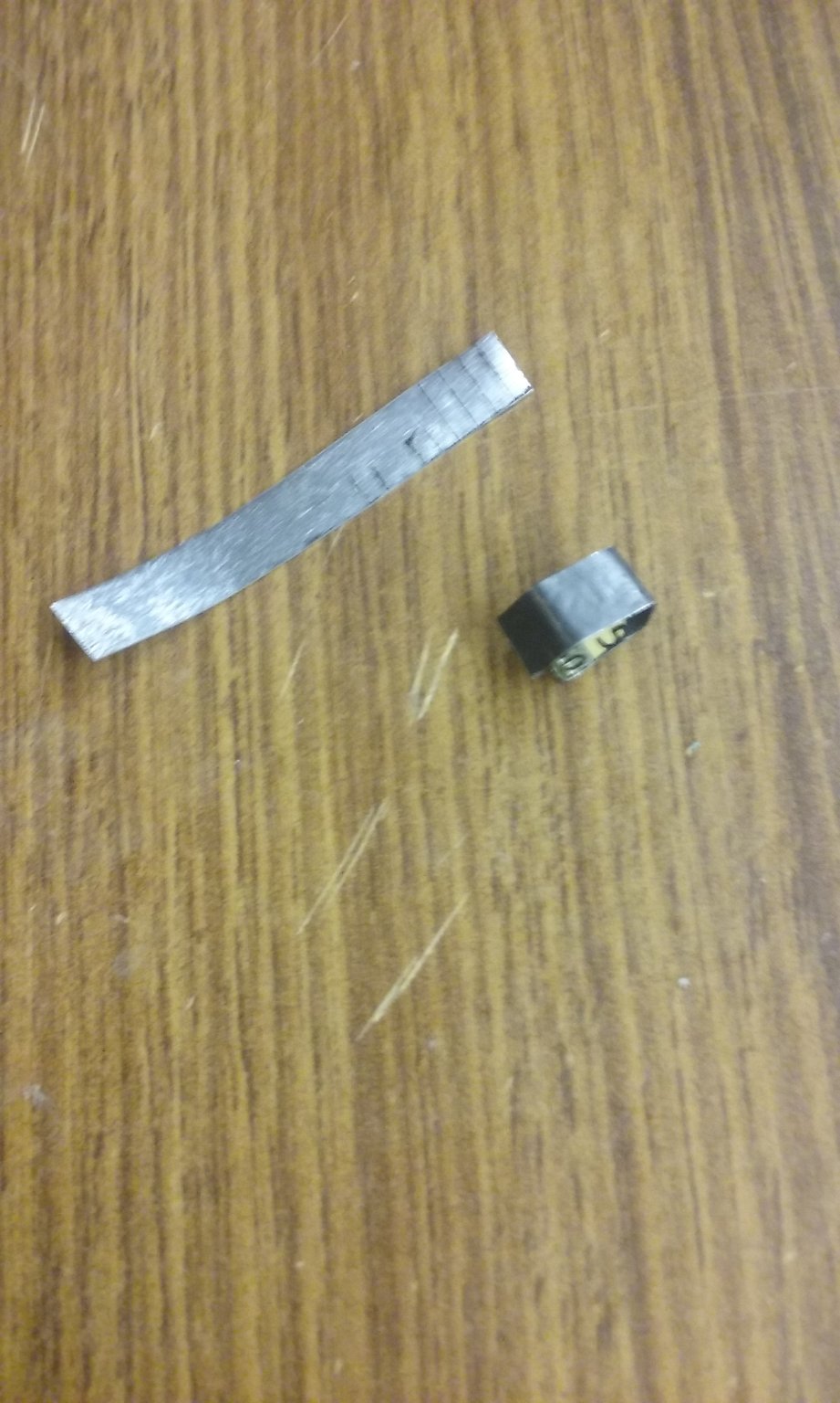
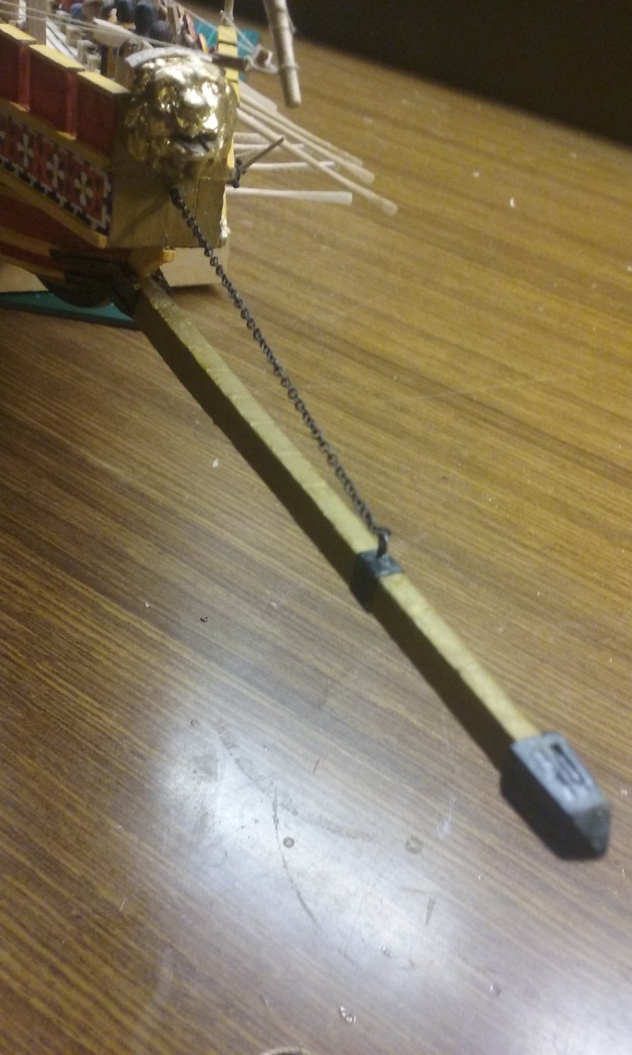
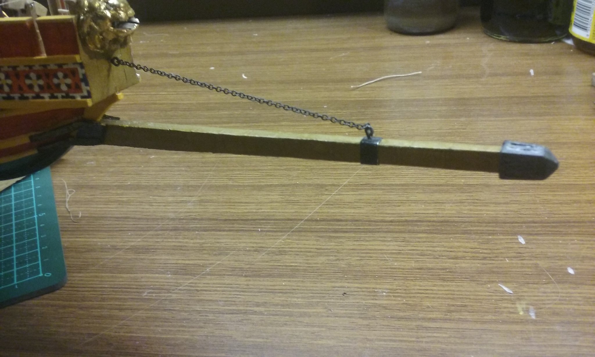
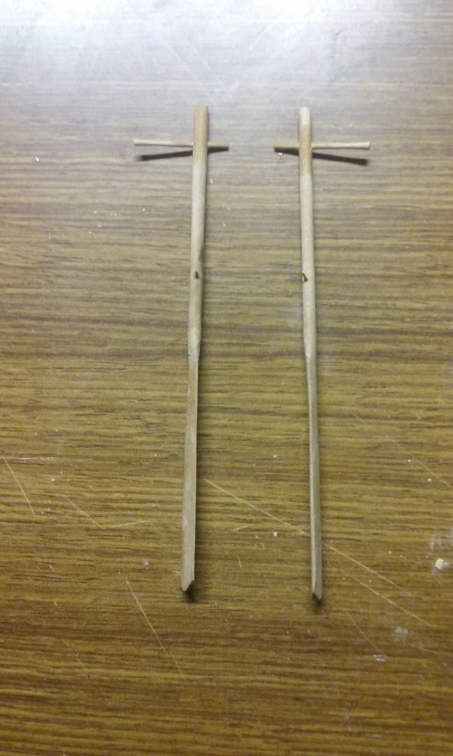
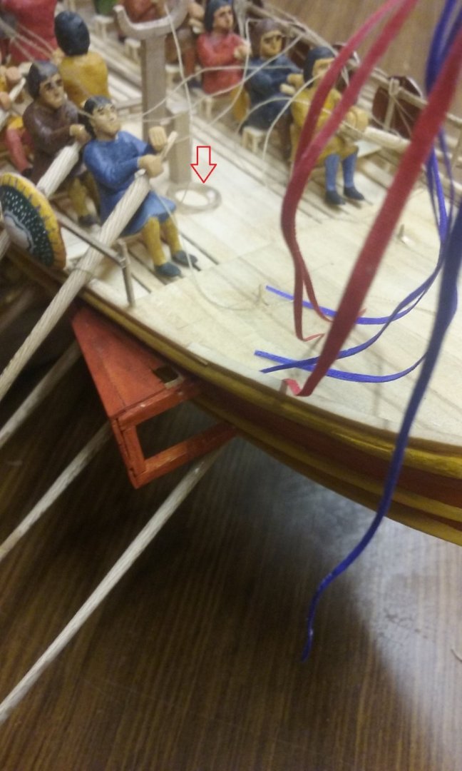
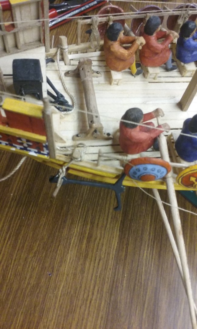
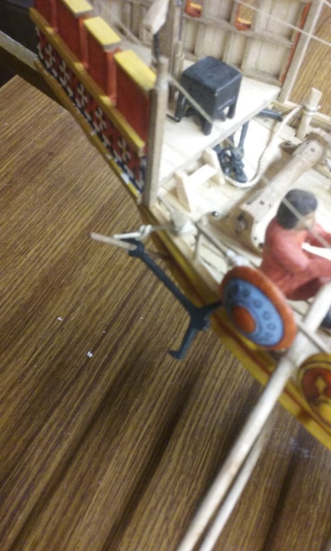
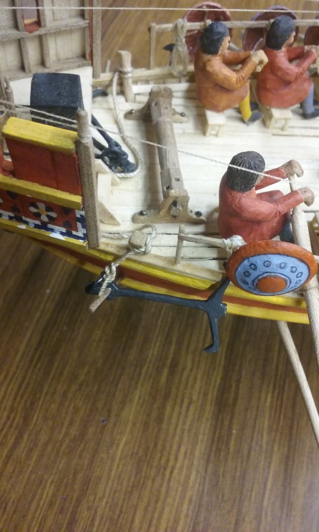
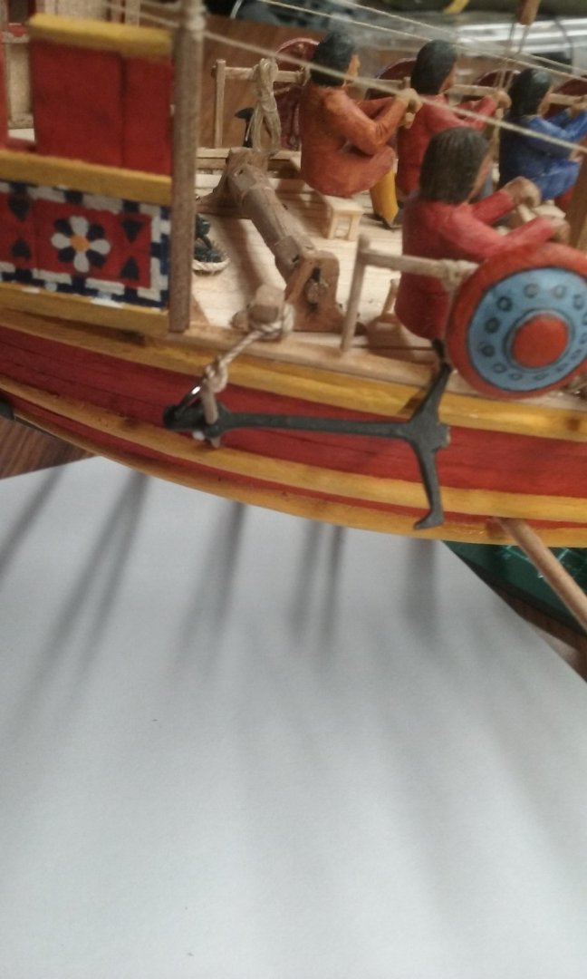
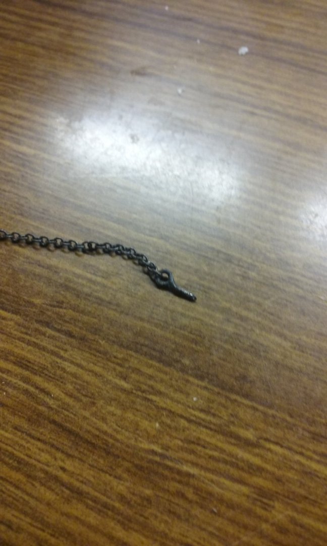
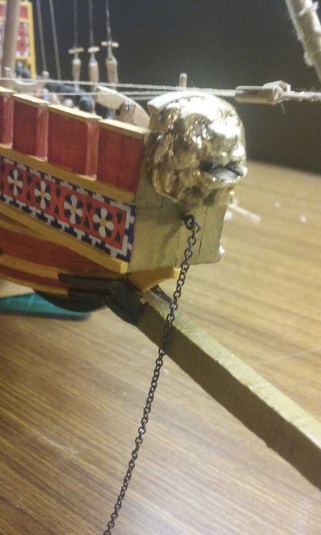
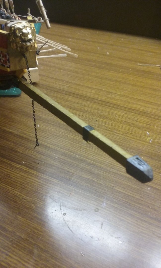
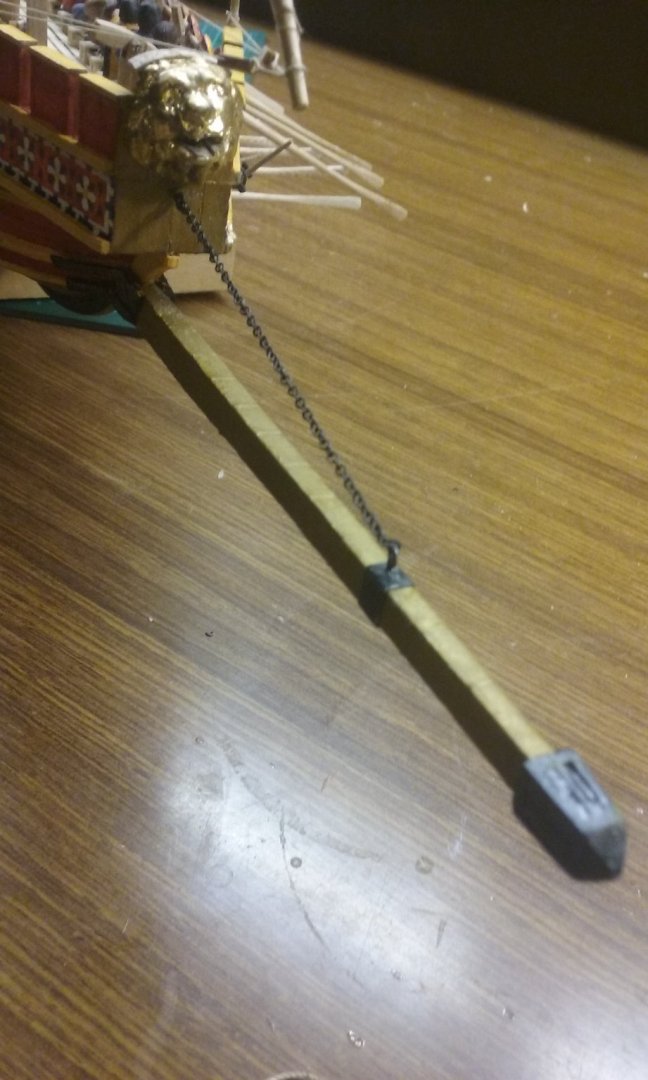
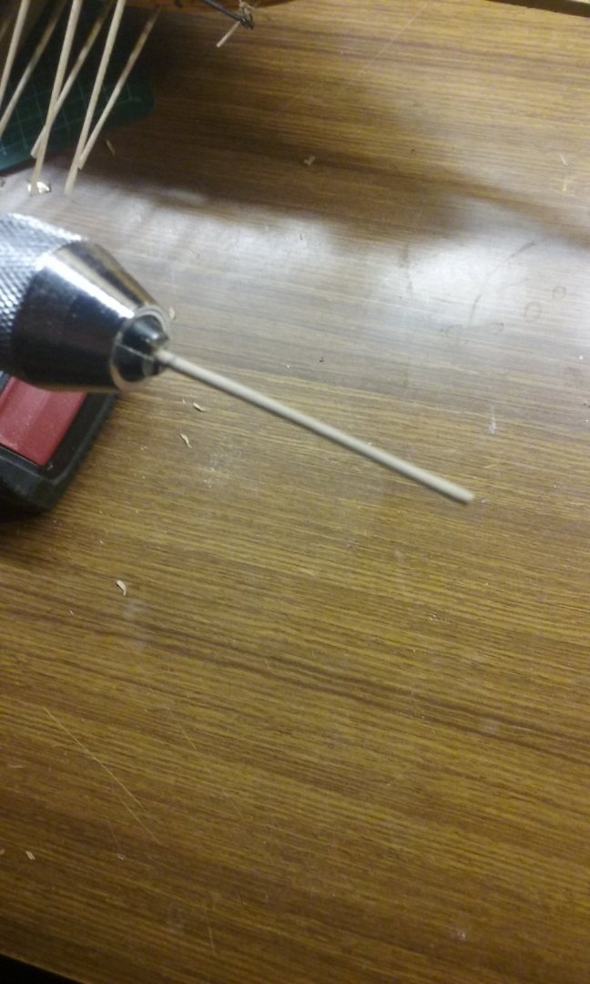
Thanks, Wolf. That's very flattering (blush) Okay, I bit the bullet and installed the anchors and cables without involving the windlass - they're catted and fished, and the cables vanish under the forecastle as though they're coiled there. I'm not sure if I should cut the free end of the anchor cable a little shorter. It looks like it might be a little long. And I did something I've been wanting to do for a long time, and which I wasn't willing to do until I was near the end in case I broke it while working on other things - I've finally added the chain that supports the ramming spur at the bow. I attached the chain to one of the eyebolts I'd prepared earlier. Then made an "iron" (actually thin aluminium from a catfood container) strap to go around the spur. And drilled a hole in the front face of the forecastle, inserted the eyebolt and added a dab of CA glue to keep it in place. I cut the chain to length and added another ringbolt on the other end. Then put the strap on the spur and glued it on with CA, and drilled a hole in the top for the second ringbolt. And inserted the ringbolt and glued it in place. VOILA! And I've started making the tillers, using the "poor man's lathe" That's all till next time.


-
It seems a bit of a shame to do all that work for something so beautiful, that won't be seen when you're finished. The sigmoid scarphs (wonderful term) are very attractive, both on the "gunwale" (guns haven't been invented yet) and the planking.
-
Maybe these would be more up your alley. They're pre- Viking (mid 7th century), so not really appropriate to your build - the first is the British Museum's replica of the helmet found at Sutton Hoo in the U.K., the second is one of several found at Vendel in Sweden. I like the way the eyebrows form the wings of the dragon on the sutton Hoo helmet.
-
Nice idea, Pat. But I don't want to go all "19th century sophisticated" on this - I'd like to keep everything as simple as possible, as it was before 700 years of extra evolution. I'll just cat and fish the anchors, lead the cables under the forecastle and leave it at that.
-
It certainly looks like one. If so, it's the earliest representation I know of. The oldest I've previously come across were early 15th century. This is a really interesting build, of a unique vessel. Keep up the good work. By the way, I think you're right in using the reconstruction as a guide but making your own judgments about the original form of the ship for your model.
- 179 replies
-
- 3
-
-
- longship
- Helga Holm
- (and 1 more)
-
I'm enjoying following this one - if only to see the physical results of all that theoretical preparation you did.
-
I thought of that, Phil. Unfortunately there's nowhere to put one without it getting in the way. Druxey, that was terrible (but in a good way) . Yes, whatever else, if I install a windlass in a future build I'll have a better idea of how it all works in relation to everything else. I have to say I'm learning a lot. They reckon that the best way to avoid Oldtimer's disease is to create lots of new neural pathways by doing and learning new things. At this rate, I'll never get it.
-
What's wrong with these photos? For those who answered "the anchor cable is at the wrong angle to the windlass" go to the top of the class. And there's no way I can move the windlass to change the angle - there's no room. Looks like I won't be using the windlass for the anchors after all (sigh). Oh, well -the crew will just have to rely on brute force to raise the anchors.
-
Ahh, there's nothing like positive thinking. And that's certainly nothing like positive thinking . . .
-
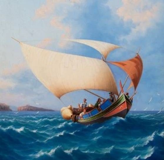
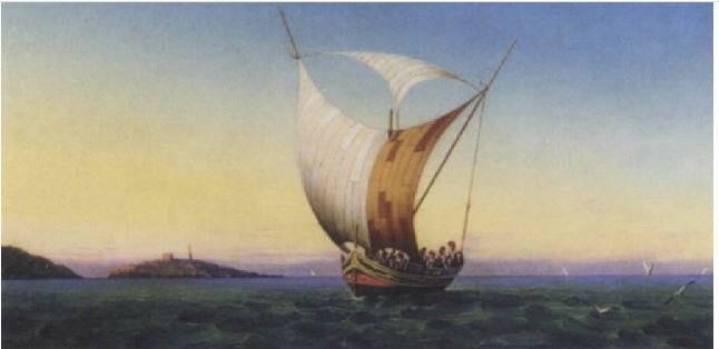
Double spritsail rigging
Louie da fly replied to Thanasis's topic in NAUTICAL RESEARCH GUILD - News & Information
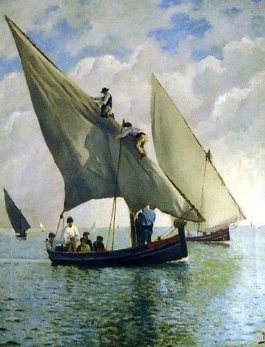
Yes, it appears to be a similar rig to a Maltese Luzzu, though your photo shows only one diagonal sprit per mast. (Apparently these vessels no longer exist - a pity, they're really cool).