ccoyle
-
Posts
10,556 -
Joined
-
Last visited
Content Type
Profiles
Forums
Gallery
Events
Everything posted by ccoyle
-
Hello, David! A good teacher friend of mine recently retired from Rim of the World High, not far from you.
-

kit review 1/72 Wütender Hund by Shipyard - Hanseatic Cog
ccoyle replied to ccoyle's topic in REVIEWS: Model kits
Dunno -- but I will build it anyway! 😉 -
Welcome! That particular kit is a popular beginner's project, and there are plenty of finished examples here on the forum. Very interesting place to be from, San Andres Island -- I had to Google it. Cheers!
-
kit review 1/72 Wütender Hund by Shipyard - Hanseatic Cog
ccoyle posted a topic in REVIEWS: Model kits
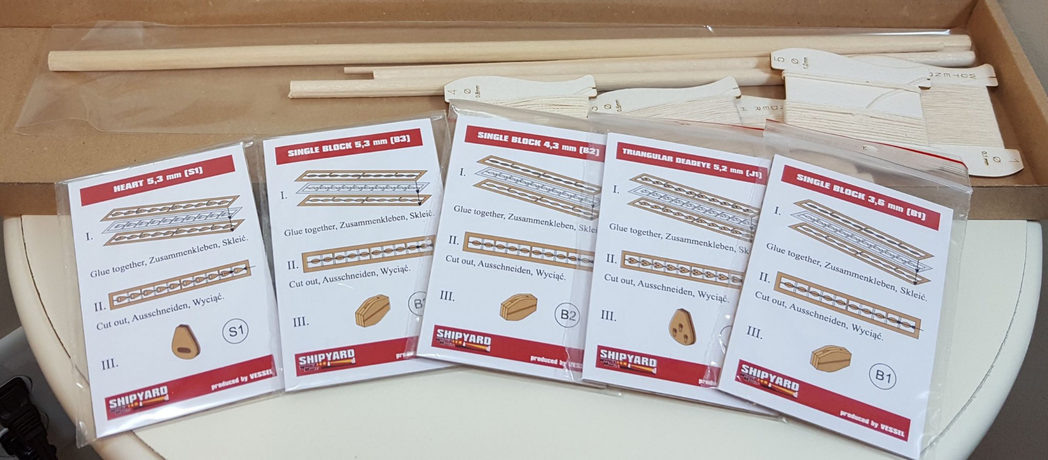
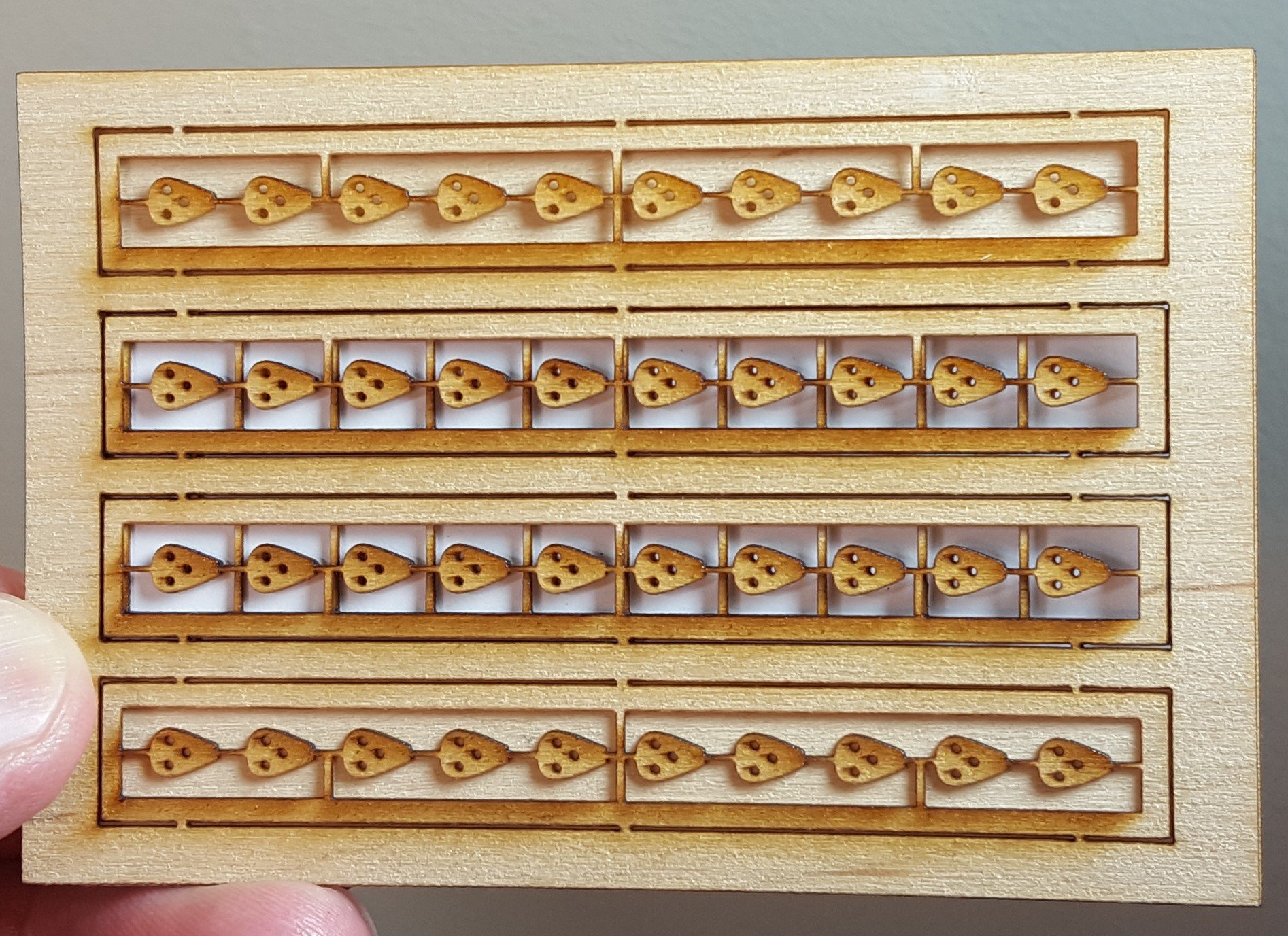
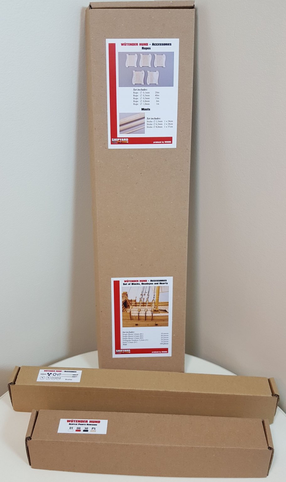
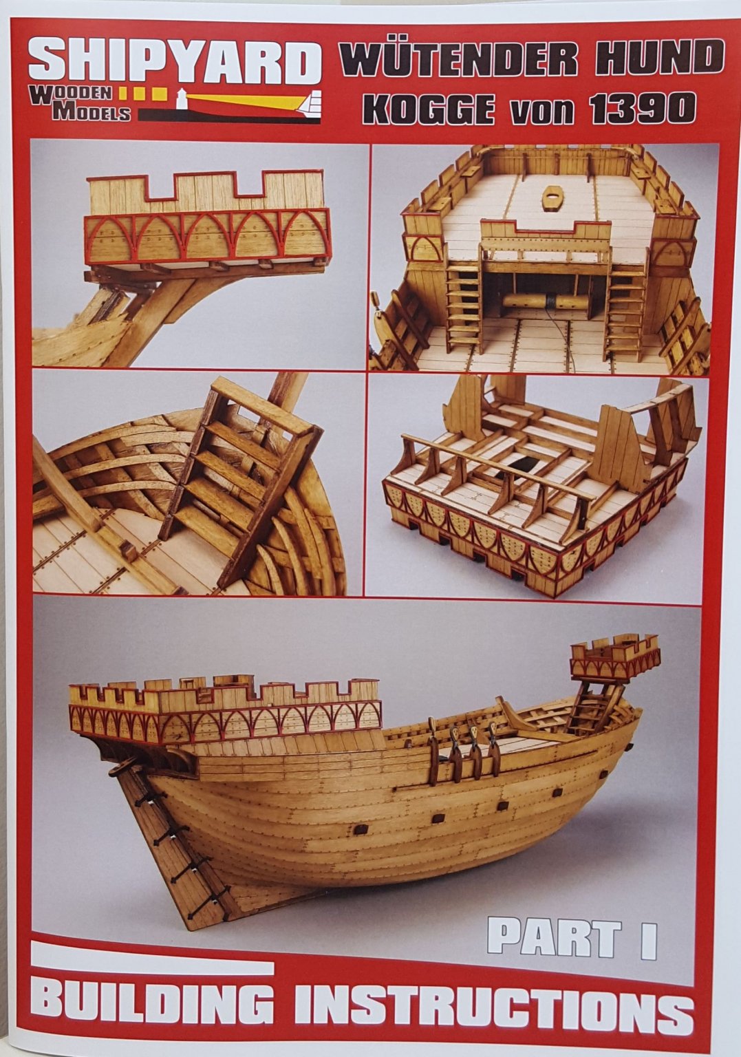
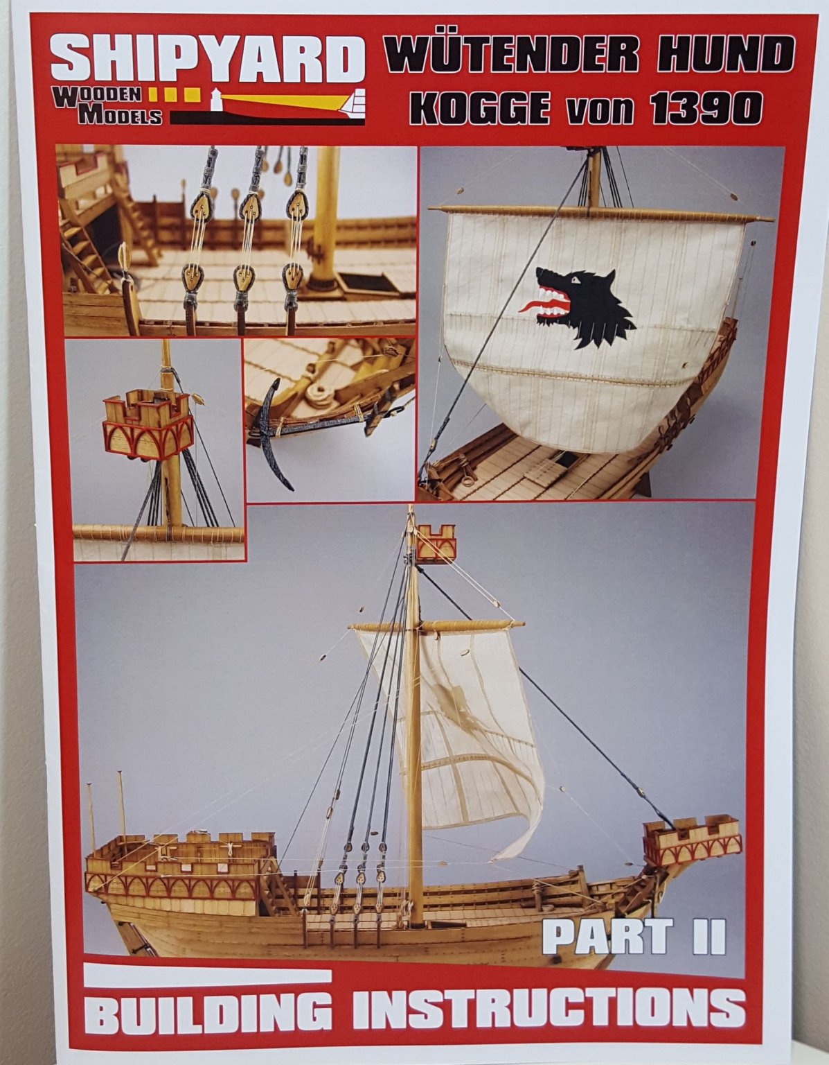
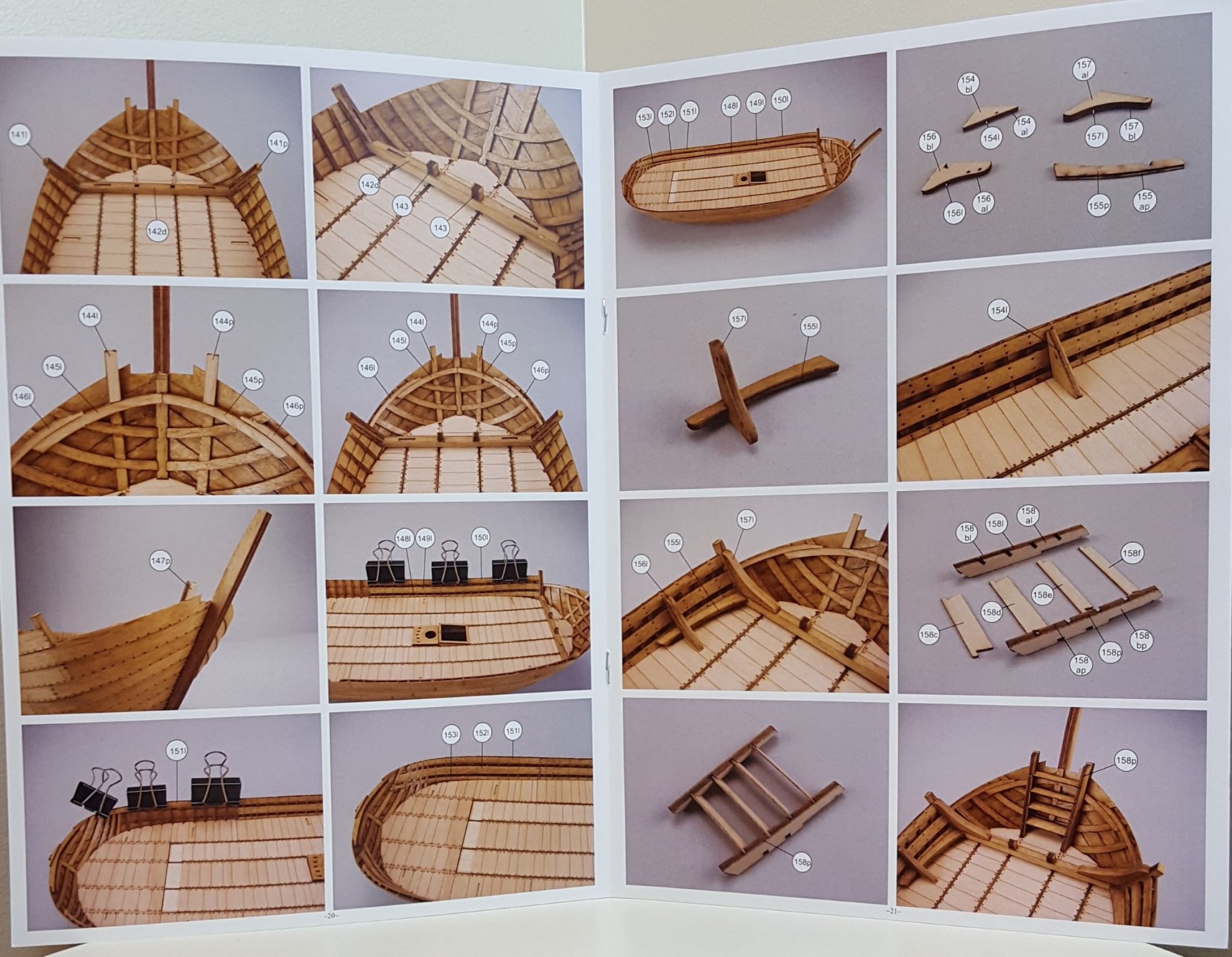
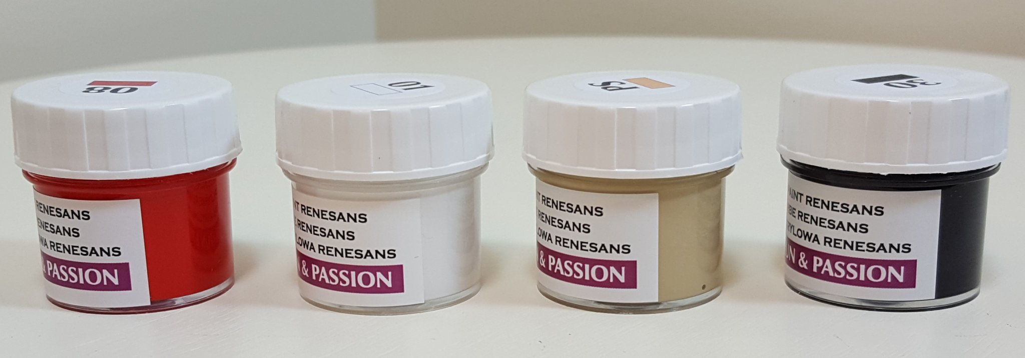
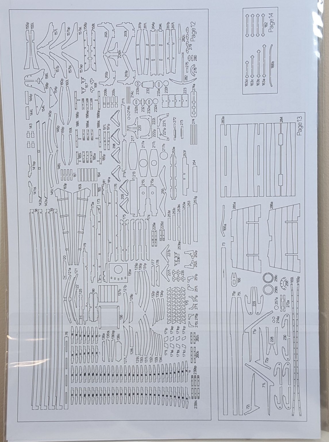
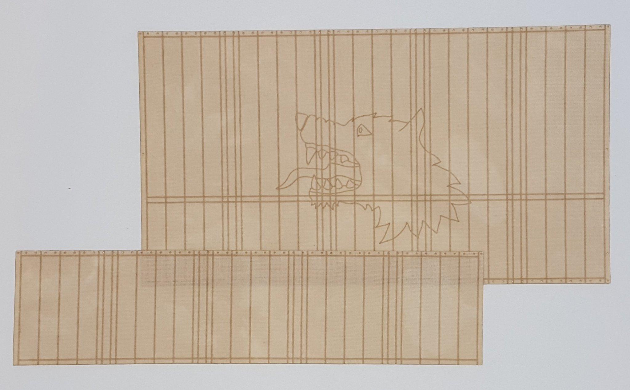
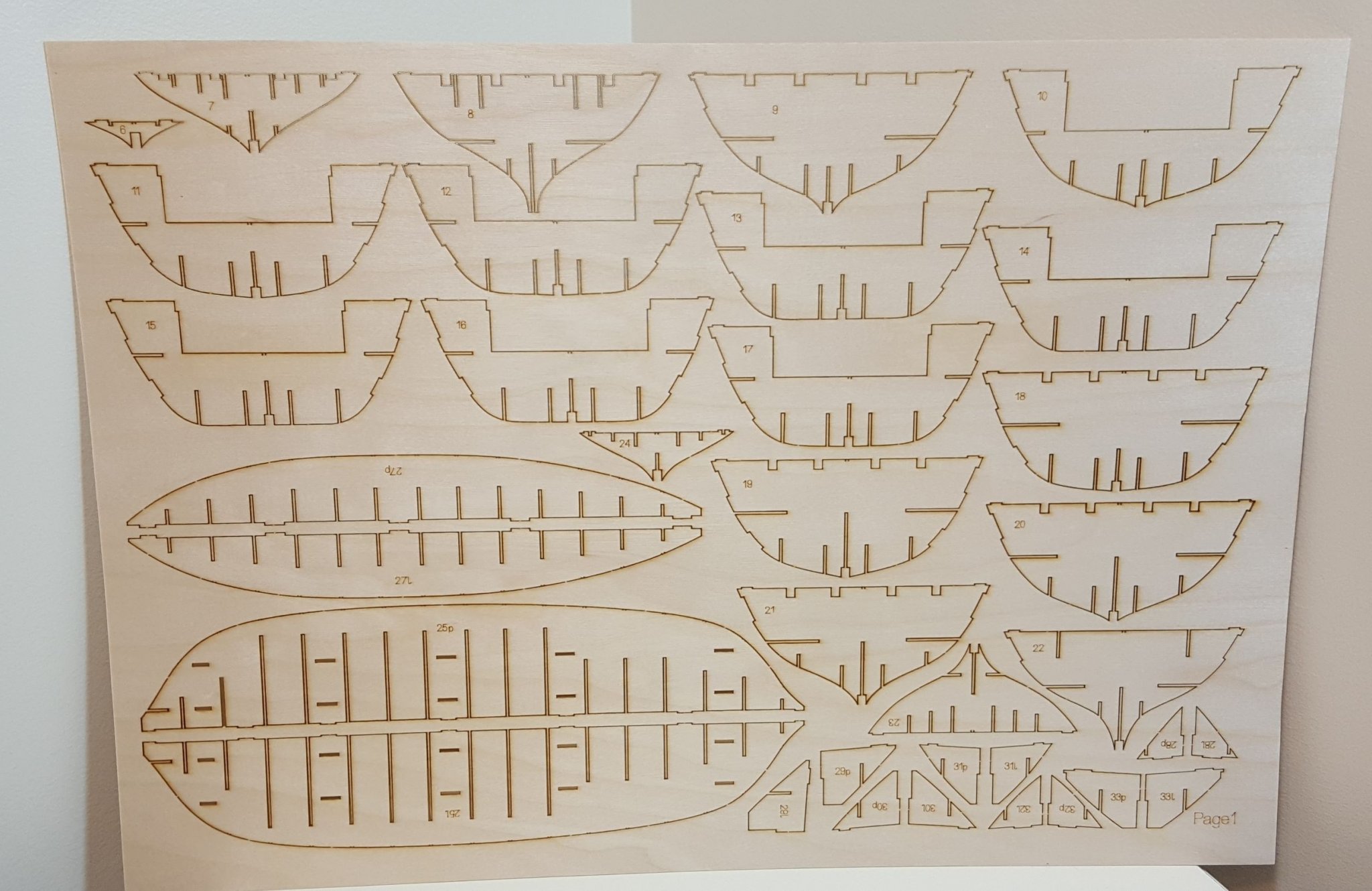
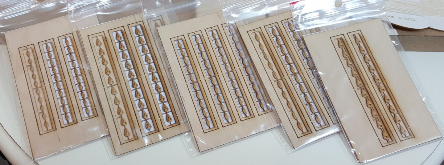
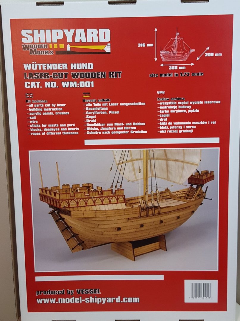
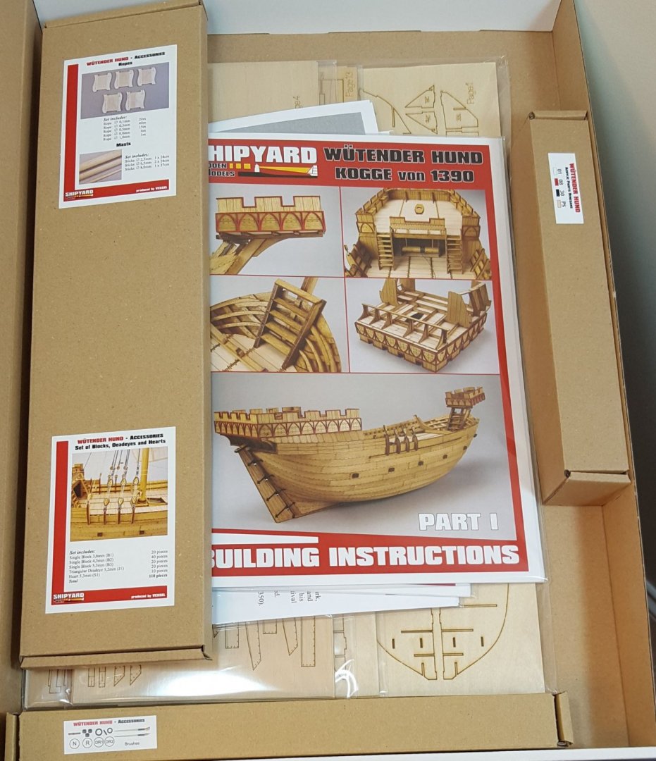
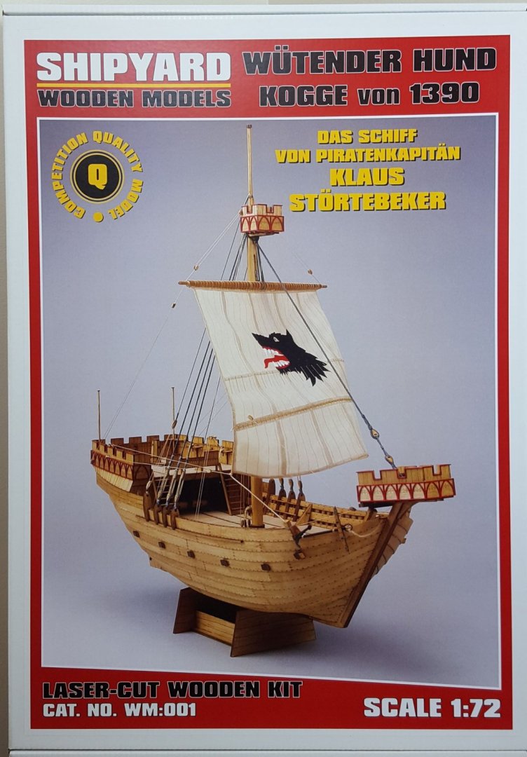
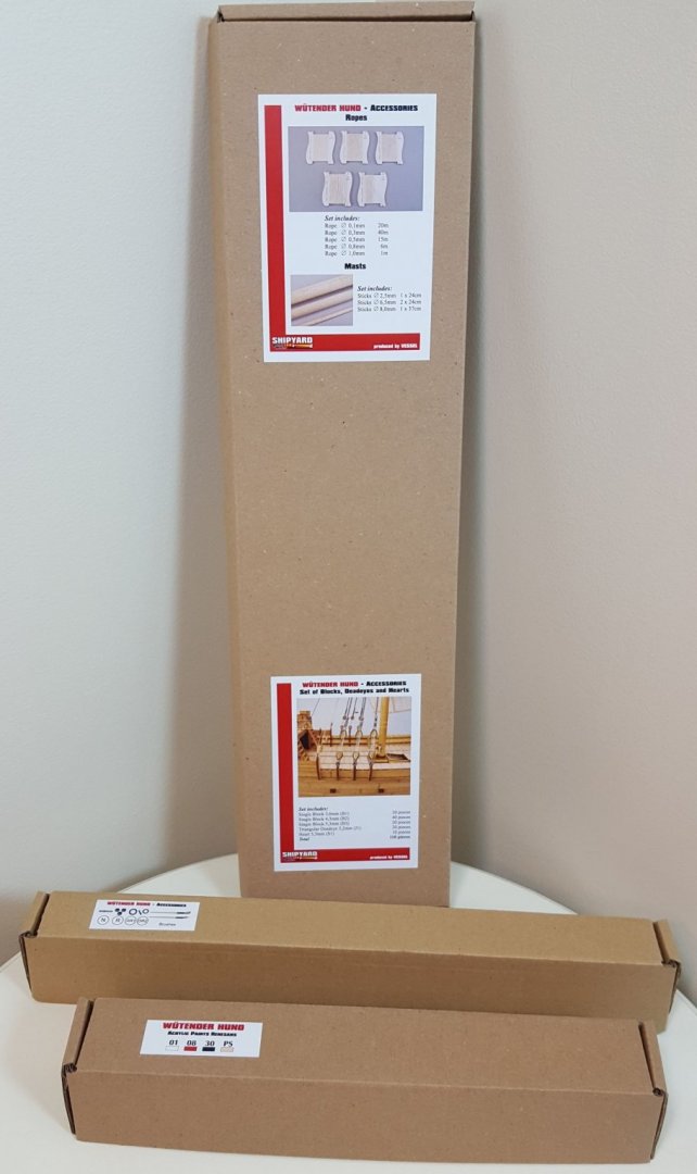
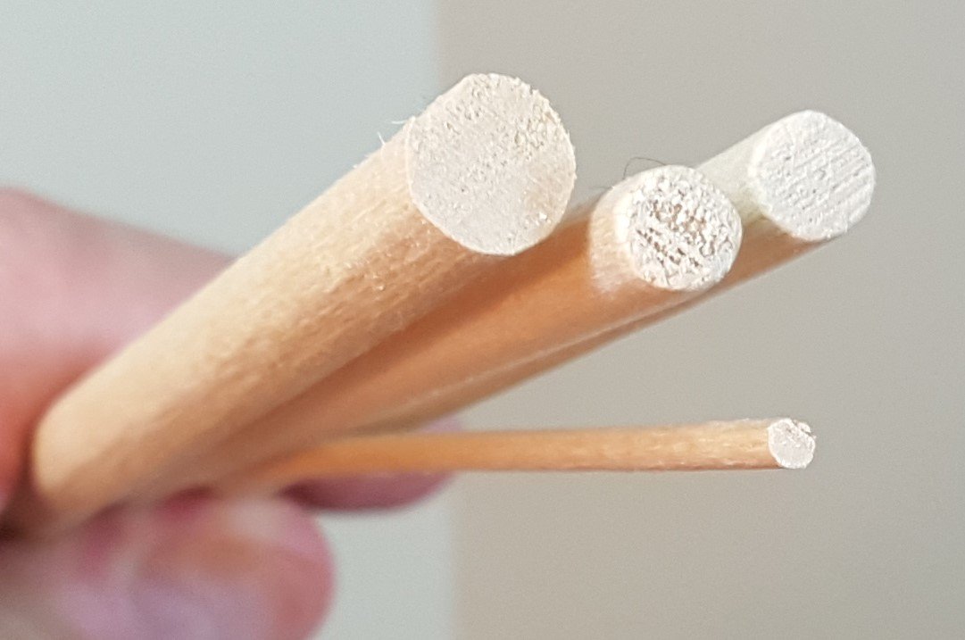
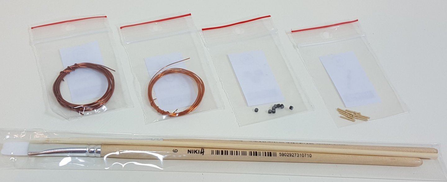
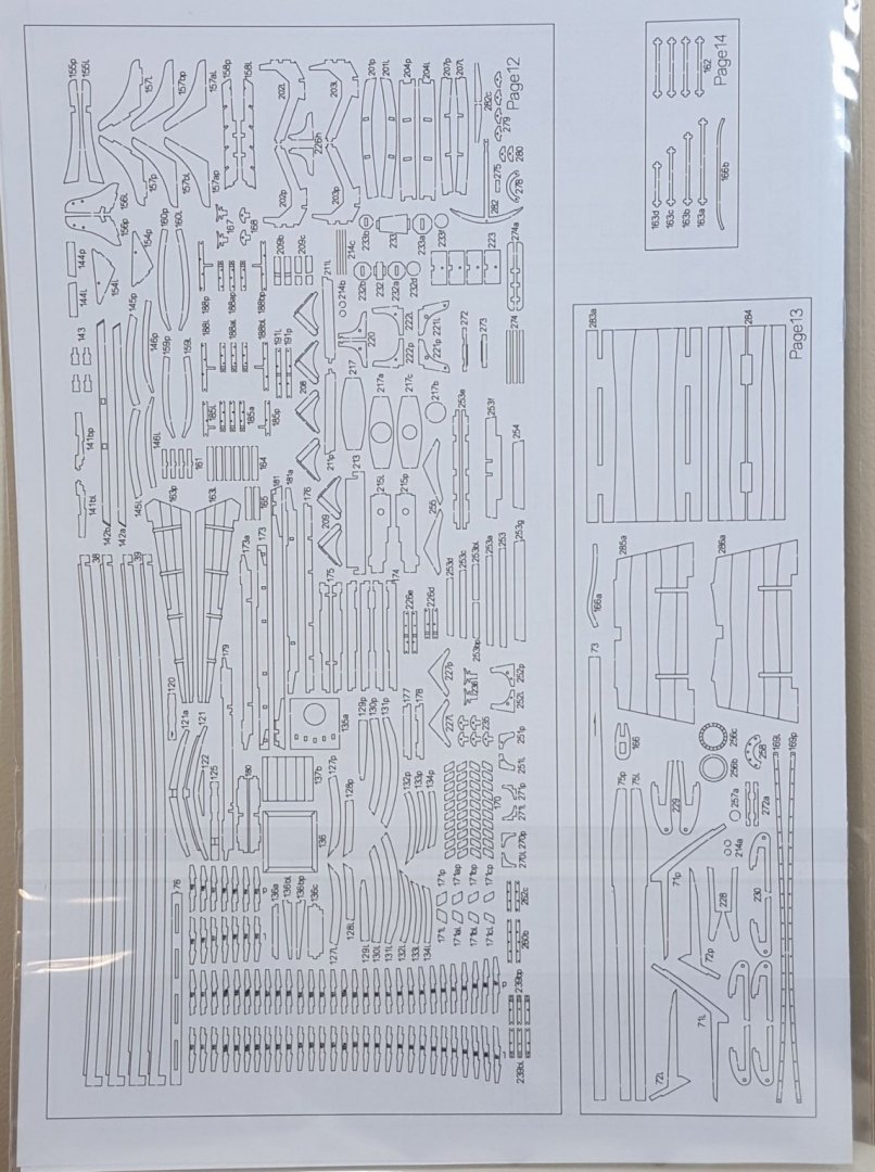
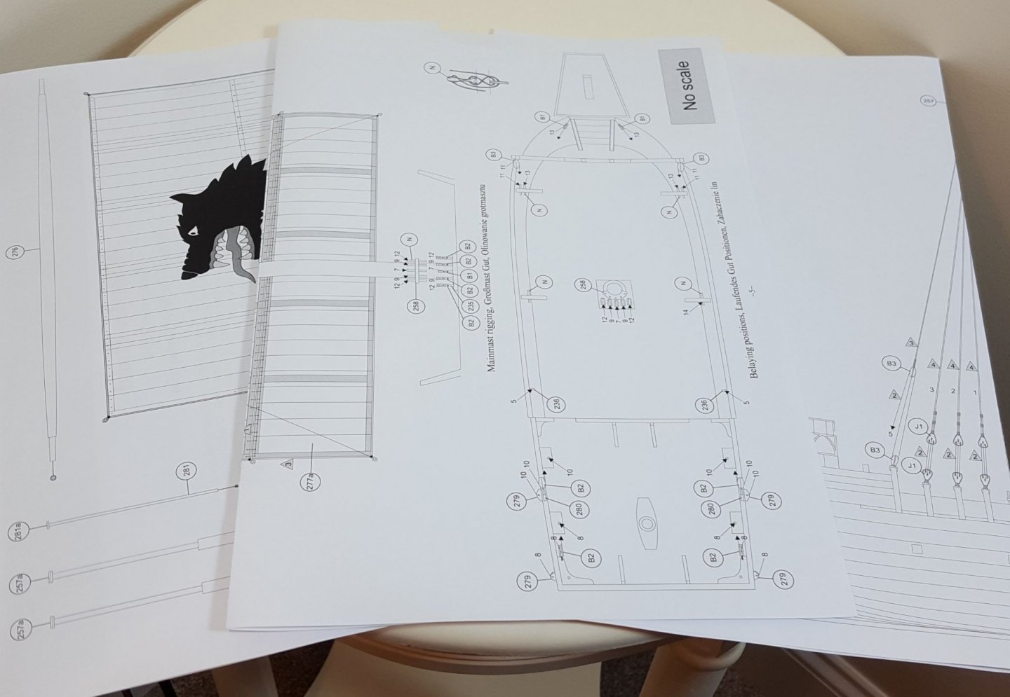
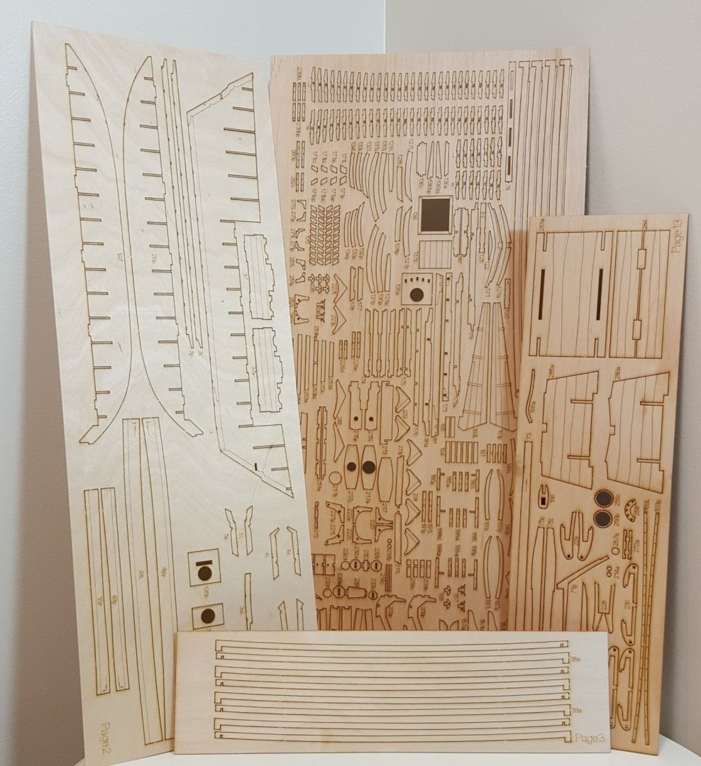
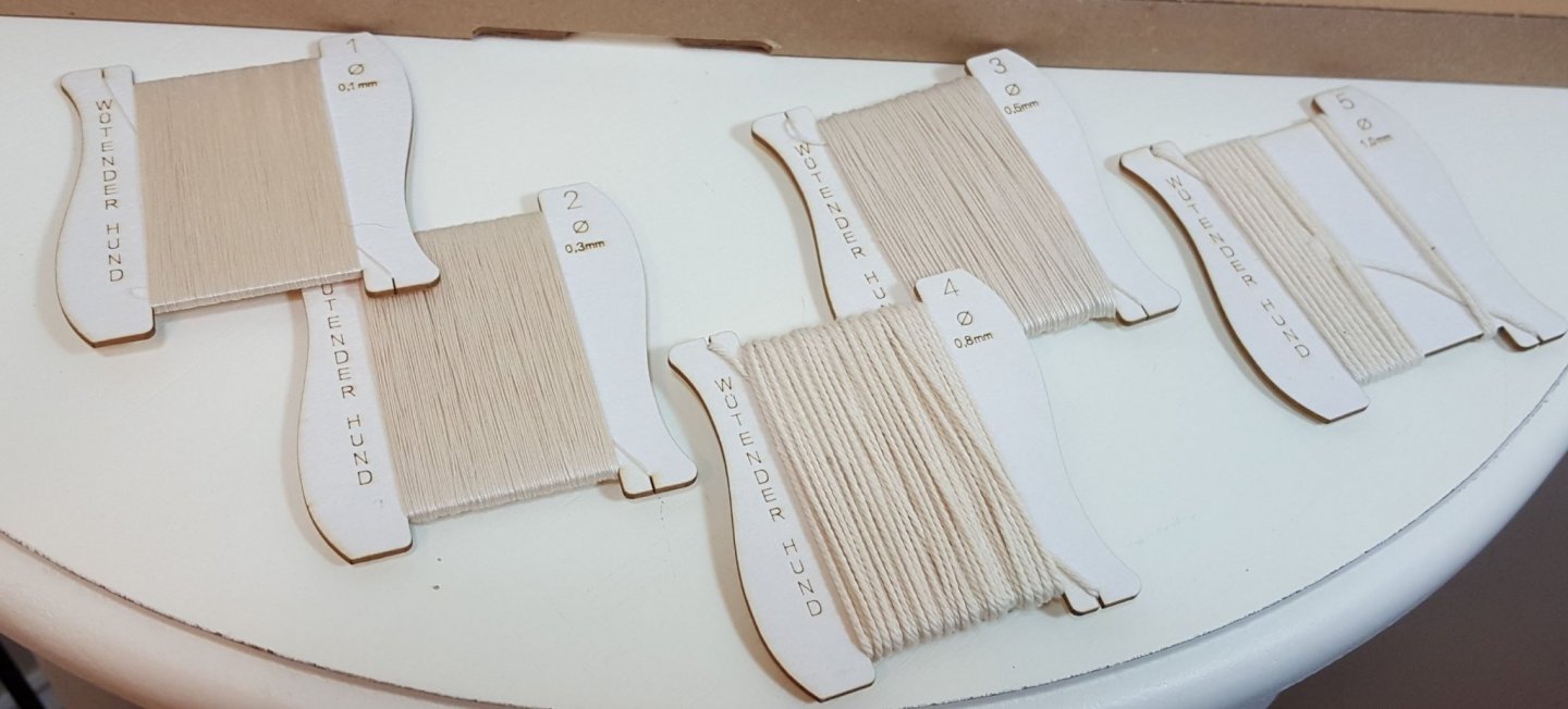
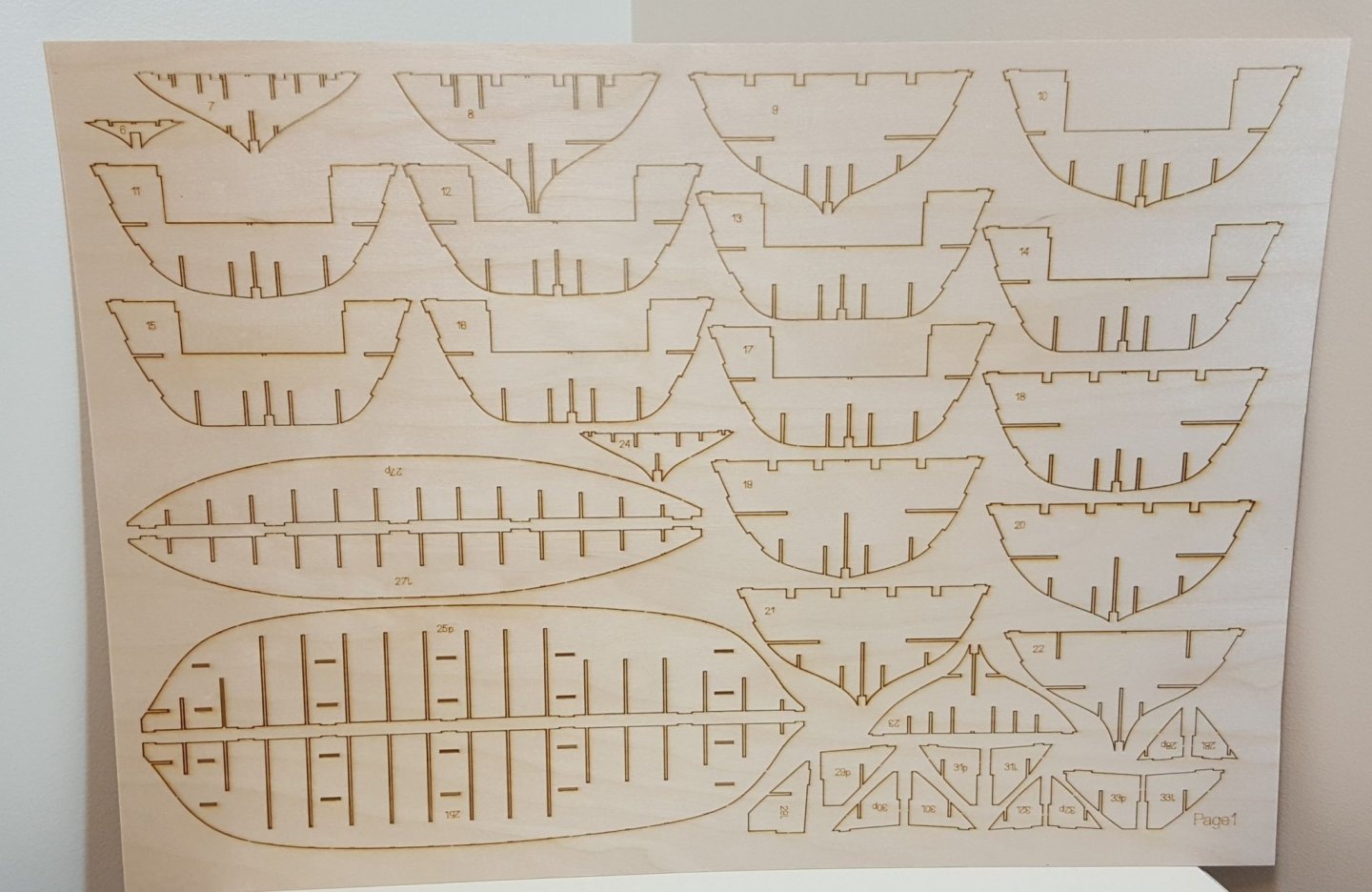
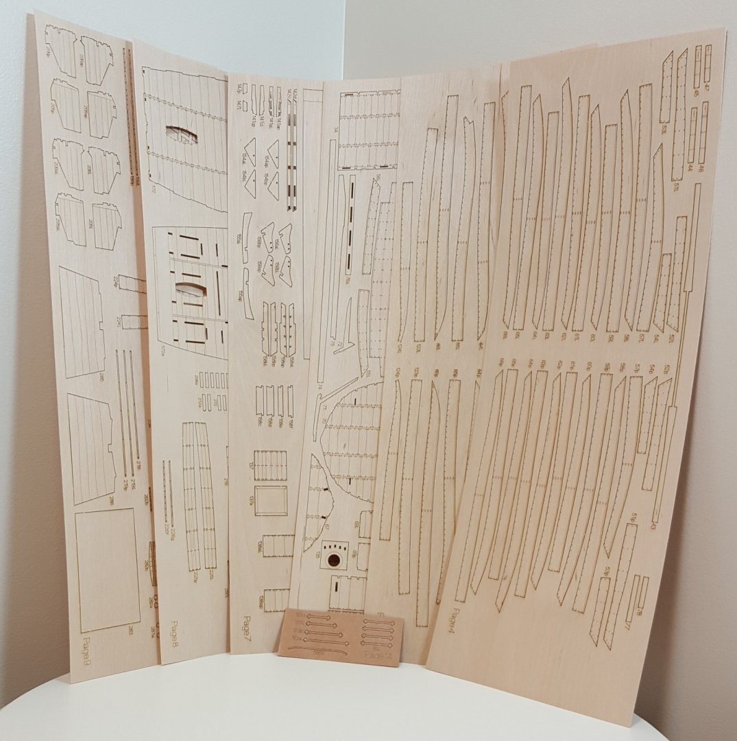
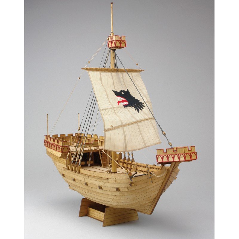
1/72nd Scale Wütender Hund - Privateer Klaus Störtebeker's Cog Shipyard **Now available as of 03/2020** (A note about this review: I am not James! Which means that I do not currently possess a slick photography setup, nor do I have photogenic hands. 😋 Judge the photos accordingly!) Polish designers have been in the vanguard of card model kit development for decades. One Polish company, Shipyard, has established a deserved reputation for high-quality card model kits of sailing subjects, usually in 1/96th scale. A few years back, they started producing what they call, thanks to the vagaries of translating Polish into English, “laser-cardboard” kits in 1/72nd scale. These kits included laser-cut parts, a set of laser-cut formers, and all of the fittings and materials—including paints and brushes—needed to finish the model (everything except glue). With the release of Wütender Hund, Shipyard have now entered into the wooden kit market as well. After all, paper is just processed wood, right? When I first read about this impending release, I was keen to find out if Shipyard’s venture into wooden kits would produce something on par with their top-notch paper kits. After a quick glance through the kit’s contents, I think that it’s safe to say that Shipyard has come up with a winner. Ready? Then let’s take a look! Wütender Hund was the vessel captained by Klaus Störtebeker, the leader of a group of North German privateers that were active at the end of the 14th century. The ship is an example of a cog, a common type of merchant vessel during the Middle Ages. The name “Wütender Hund” roughly translates as “mad dog.” When completed, Wütender Hund is 355 mm long by 316 mm high and 200 mm wide. Upon its arrival at my door after its long trip from Puszczykowo, Poland, I was pleased to find that the good folks at Shipyard had packed the shipping box very well, with plenty of cardboard to stiffen it and packaging peanuts to help it survive stops in Poznan, Arnhem, Cologne, and Liege on its way to America. Neither the kit box packed inside nor its contents were damaged in any way. The kit box itself is 500 x 350 x 50 mm in size and features bold graphics, details about the kit, and photos of the prototype model. It comes protected inside a clear plastic shell. Opening the box reveals three smaller boxes along with plans, instructions, and sheets of laser-cut parts packed in clear plastic sleeves. There was no packing material inside the box, but then again there isn’t really anything inside that could be damaged by simply sliding around. We’ll start by unpacking the mysterious inner boxes! Inside the largest of the boxes are rigging materials. Wütender Hund has a very simple rig, having only a single mast and one yard, so there isn’t a whole lot of dowels in the kit—three, to be precise (the smallest-diameter dowel is intended to be used as a glue applicator). One dowel had a slight bend at one end, but the remainder were nice and straight. (I think there's a dog hair in the photo -- I have three dogs, and one of them is a shed-o-matic!) Five diameters of rigging cordage are provided, from 0.1 to 1.0 mm. All of the rigging is left natural; tarred rigging will need to be colored. Blocks and hearts are laser-cut. Each block or heart is built up from multiple layered parts. The inner parts are smaller than the outer parts, so that the finished hearts will have a groove for stropping. (Edit: Having now built up a few of the blocks, I can say that these turn out very nicely.) Moving to the next box, we find individually bagged materials and tools. Two diameters of copper wire are provided for making various metal parts. These and the turned brass belaying pins will need to be blackened. One bag contains tiny pieces of cut plastic tubing that will be used for making gudgeons. Two paint brushes, one square-tipped and the other round, are provided. They appear to be white sable or similar. (Edit: I prefer pre-blackened annealed wire and will substitute that during construction where possible. The cut plastic tubing gets covered by the card stock during the construction process.) In the last box we find a set of four acrylic paints: black, red, white, and beige. (Edit: The paints give very good one-coat coverage.) There are a whopping 14 sheets of laser-cut parts. The laser cutting is very good, and char on the reverse sides is minimal and easily removed. Many of the parts are veneers, so their reverse sides are not even visible on the finished model. The thickest ply sheet contains hull formers. Unlike some wooden kits, these do not have fairing lines engraved on them, but since the bulkheads are thin, they will not need much work in that department. Other parts are cut from different shades of plywood (walnut is my guess), which should produce some pleasing contrasts on the model. Plank seams are laser-engraved. (Edit: After completing much of the hull, it's safe to say that the plywood quality has been very good, no matter the thickness of the sheet. There are a few blemishes here and there, which is to be expected in plywood. The plywood takes stain very well on the engraved side, but the reverse side not so well; this affects relatively few parts of the model.) The thinnest sheets contain veneers that will be applied to various parts of the model. These also have laser-engraved details, which I personally find rather remarkable when considering how thin these actually are, i.e. engraving lines nowhere cut completely through the material. The smallest sheet is brown card stock and contains parts that will need to be painted to simulate ironwork, such as rudder hardware. (Edit: I'm not sure what kind of stock is used for the iron work, but it is tough, molds to contours well, and after painting does a very passable job of looking like real iron work.) A complete suit of pre-cut and pre-printed sails (two -- whoa, nelly!) is included. The striking “mad dog” will need to be painted. As you can see, that’s a lot of parts! Happily, a complete parts list is provided, featuring labeled drawings of every parts sheet. Sixty-four pages of full-color instructions in two booklets walk the builder through the construction process. Book 1 covers hull construction, while Book 2 covers masting and rigging. (Edit: The photo instructions have been great! There have been only a few minor questions raised about what exactly to do, but so far I have been able to figure everything out. If anything, there might actually be more photos than than are necessary, but I'm not going to complain.) The instructions are almost entirely photo-based and include very little text, but the build sequence is thoroughly outlined by the high-quality and plentiful photographs. This format will feel familiar to card modelers. Two single-sided and one double-sided plan sheets are included. These include hull plan and profile views, masting and sail plan, and rigging plan. Shipyard’s extensive experience with both laser-cutting and the production of card model kits has enabled them to do a superb job of bringing to market what is essentially a card model in design that is constructed in wood rather than paper. (Edit: This extends even to having to attain proper parts thicknesses by laminating two or more parts together. Again, this is familiar to card modelers, but may be something unexpected to modelers who have only built the usual kinds of wooden models.) The quality materials, colorful instructions, and attention to detail suggest that Shipyard are sincere in their desire to bring together the best of both modeling media. Have they succeeded? I think they have, and I’ll probably find out for certain in the near future, as this kit practically begs to be started sooner rather than later. My sincere thanks go to Shipyard for providing this kit for review, and I hope that it becomes a big seller for them. For those interested in buying the kit, Ages of Sail, an MSW sponsor, is the US distributor of Shipyard products. For those wishing to stick to card models, Shipyard also offer a laser-cut cog kit in 1/72nd scale as can be seen here being built by Clare Hess and reviewed here. Cheers!


-
Great job, Don! That is a fine model indeed and a testament to your skill and determination. Cheers!
- 120 replies
-
- 2
-

-
- crabbing skiff
- Chesapeake Bay crabbing skiff
- (and 3 more)
-
Yes, but you are very close to finishing! Nice work!
-
Ah, but you don't have to wait! The link is embedded in the intro in the first post.
-
Will probably get bumped to somewhere very close to the top of the queue -- along with finishing the MK Kanonen Jolle, the Okumuto Hannah kit, any number of 1:33 card planes, and my full-size Sassafras 12 canoe. Whew!
- 175 replies
-
- 8
-
-
- hanse kogge
- shipyard
- (and 1 more)
-
You can reply to the thread I started. I'm sure folks wouldn't mind seeing more. That's the kit that is on its way -- stuck in Liège, Belgium, at the moment. 🤔
- 175 replies
-
- 4
-
-
- hanse kogge
- shipyard
- (and 1 more)
-
That doesn't sound right. I got a small bottle (0.85 oz) at the hardware store for about five or six dollars.
-
Ah. I have used CA on all of my hulls up to this point, but never on one that I intended to leave as bare wood. Leakage between planks and even through the wood itself comes with the territory with CA. On my latest model, I have used a product called Rapidfuse from DAP. I believe it is a CA derivative, but not nearly as messy. It sets in 30 seconds and is completely dry in three minutes. With any CA product, it is important to apply the bead of glue down the center of the plank, because it will spread when pressure is applied. Hope this helps a bit.
-
Clare, you did such a fine job on your introductory post that I took the liberty of copying it into the kit reviews section -- hope you don't mind!
- 175 replies
-
- 5
-
-
- hanse kogge
- shipyard
- (and 1 more)
-
Hello, friends! MSW member Clare Hess did such a bang-up job of describing this Shipyard kit in the first post of his build log that I took the liberty of copying it to create this review. You can find Clare's build log here -- and knowing his work, this will be a good one to watch! ______________________________________________________________________________________________________________ Earlier this year, I managed to acquire a relatively new kit produced by the Polish card model kit maker Shipyard. The kit is one of two that were released at least a year ago, maybe longer. Both kits represent medieval Cogs from the 1300s. Unlike other Shipyard kits I've worked on (yes, I only finished one paper ship model kit, but started a couple of them) which were paper kits and required cutting out pre-printed parts, this is a laser-cut card stock kit. Everything is already cut out in this type of kit, and the model requires painting. The kit I am building the kit listed by Shipyard as the Hanse Kogge - Bremen 1380. It is a 1/72 scale laser-cut kit based on the Bremen Cog. The completed model measures a little over 13" long and about 12.5" high. I decided to go ahead and take on this kit, though I have other projects, as the laser-cut design should make construction much simpler than the paper kits I've worked on. Ages of Sail, which is how I got my kit, sells this kit for about $125. There is a second Cog kit available called the Wütender Hund. It's a slightly bigger kit, maybe a little more complex, that sells for about $10 more. If you're interested in buying one, I'd really like to see other build logs! Here's a link to the kits on Ages of Sail: https://www.agesofsail.com/ecommerce/catalogsearch/result/index/?cat=72&q=Kogge So, taking a look at the contents of the kit... The laser-cut parts are in a cellophane envelope, individual carboard boxes keep things from knocking around in the main box and contain parts, paints, etc. The instructions make up a full-color booklet filled with photos. There's very little text, and what there is in multiple languages. Parts that aren't part of the laser cut sheets are provided in a couple cardboard boxes that include rigging line, laser-cut blocks and deadeye sets, paints, brushes, dowels, metal accessories, etc. The sail is pre-cut and pre-marked, but will need to be painted. There are several sheets of laser-cut card stock in various thicknesses and finishes. Some of the sheets have a glossy finish. Here are just some of the sheets. There are a couple sheets of plans included, which mostly cover rigging details. This looks like a very good kit and I'm pretty happy to be able to work on it. Next time, I'll post the start of construction. Clare
-
It can be tricky to find, but it is available here.
-
The kit will be produced by MarisStella, and based on the quality of their previous kit offerings (look for finished examples in the galleries), this kit should be very, very good. http://www.marisstella.hr/
-
That's in the neighborhood of where the mainsail sheet is belayed.
-
Outstanding, Clare! BTW, a Wuetender Hund kit is on its way to South Carolina even as we speak -- review to follow soon after!
- 175 replies
-
- 6
-
-
- hanse kogge
- shipyard
- (and 1 more)
-
UPDATE TIME!! Okay, not a big update, but an update nonetheless. After a forced hiatus for the move, followed finally by the move itself (#38), getting the "man cave" set up, and purchasing a suitable modeling desk, the ship yard is back in action! I sanded an oar down to shape this evening -- only took 40 minutes. Twelve more oars at 40 minutes per oar is ... lessee ... only 8 more hours to complete the oars. 🤪🤪🤪 Still -- it's progress.
-
Quick! Somebody hide my debit card!!
-
And another from the Great Pacific Northwest
ccoyle replied to Egilman's topic in New member Introductions
Welcome aboard! -
Outstanding, and very colorful!
-
De Havilland DH 60 Gipsy Moth by Mike P - 1/4 Scale - WOOD
ccoyle replied to Mike P's topic in Non-ship/categorised builds
Lovely! I have the RAF version in a 1/33 scale card model from Kartonowa Kolekcja -- somewhat smaller than yours and forever Earth-bound. -
De Havilland DH 60 Gipsy Moth by Mike P - 1/4 Scale - WOOD
ccoyle replied to Mike P's topic in Non-ship/categorised builds
Love the old biplanes! You going to dress her up as a private aircraft or an RAF trainer? -
Pretty good for a month's work!