trippwj
-
Posts
3,156 -
Joined
-
Last visited
Content Type
Profiles
Forums
Gallery
Events
Everything posted by trippwj
-
 Very nice, Sjors. Hope Anja had many copper coins in her bank for you to melt down!
- 1,616 replies
-
- 3
-

-
- caldercraft
- agamemnon
- (and 1 more)
-
I haven't been able to find the source (it may have been Charles Davis?), but he discussed the rat lines as not tarred for the reasons listed by Kester and a couple of others. 1. Reduce amount of tar tracked on that nicely holy stoned deck 2. Keep the flexibility in the finer rope used for the ratline 3. Cost - there are a lot of them rats to tar for minimal gain in service life! Realistically, they would pick up some of the darkening from the "wicking" action when shrouds were re-done, but probably not as dark as the shrouds.
-
I think the choice really depends on the piece. Is it worth the effort and waste to set up and spray 3 pieces of 1/8" x 1/4"? For other parts such as the hull it may make sense.
-
Toluene, heat gun and Dremel on her prosthesis - she is much more trusting than my mother was! That framing is looking very nice, Mark.
-
Nice gift! I am sure you will put it to good use. Nice work on your Hermione. Looking forward to the next update as well, and Happy Birthday to you, Nick!!!
-
I have submitted a review of Allan's book to the MSB Journal - should be coming out in the August edition. See below - Scantlings of The Royal Navy 1719-1805: Comparisons of 1719, 1745 Establishments, Ship Builders Repository and Steel’s Elements and Practice by Allan Yedlinsky, Published by SeaWatchBooks, LLC. 2014. ISBN-13: 978-0-9837532-9-2 From the publisher: 14”x8 ½”, semi concealed, lay flat Wiro binding, heavy paper cover, 271 pages, one color. This specially formatted book (14”x8 ½”) is divided into 2 sections. The first shows all of the scantlings from the 1719, 1745 and 1750 amended figures in an easy to use spread sheet format. The second section compares Steel and Ship Builders Repository in the same format. Additionally, the author provides notes and comments for each section. The work is presented in a lay flat binding so that when opened, 28” of information is in front of the reader. In the preface to the 1755 edition of Sutherland’s Ship-Builder’s Assistant, the anonymous editor offers the following: The advantages flowing from Shipping, are so great and conspicuous, especially to the Inhabitants of these Kingdoms, that it would be superflouous to advance Argument in Favour of the Art of SHIP-BUILDING, or MARINE ARCHITECTURE, and therefore whatever has the least tendency to its Advancement, certainly merits Encouragement. It should also be remembered that every Improvement made in an Art of such Importance to Society, adds a farther Security to the Power, Strength, and Interest of these Kingdoms. Allan Yedlinsky provides the model ship builder, as well as the naval historian, with a valuable contribution to the art in his Scantlings of The Royal Navy 1719-1805. The builder of a model ship, not unlike the builder of the full size ancestor, requires a great deal of information to build a model which accurately represents the desired vessel. While the basic dimensions of length, beam and number of guns is important, these alone fail to provide sufficient information to describe the intricacies of the vessel. To fully describe the desired result necessitates the use of a 3 dimensional description of not just the summary dimensions, but the sizes (or scantlings) for a myriad of smaller bits and pieces. In Scantlings, Yedlinsky brings together the detailed information from the primary sources of the era used to guide the building of His Majesty’s ships of war during the 18th and early 19th centuries. While other books have been published on the topic (such as Goodwin’s The construction and fitting of the English man of war, 1650-1850), none have to date pulled the detailed scantlings together in one easy to use set of tables. In Scantlings, we have for the first time all of the gritty details from the early Establishments, which were intended to standardize the construction of British war ships (actually, with humble apologies to Captain Barbossa, in practice they became “…more what you'd call "guidelines" than actual rules.”) The detailed tables of scantlings are both extensive and legible, set in a spacing and font which is easy to see without visual aids. The inclusion of the un-official (but more generally known) information from the Shipbuilders Respository and Steel’s Elements and Practice of Naval Architecture serve to extend the period covered through the Napoleonic wars and nearly to the advent of steam. No endeavor this ambitious could be expected to include every potential source of information. Yedlinsky has selected a set of valuable reference documents that are not only comprehensive in their own right, but perhaps more important, when consolidated in such a manner they offer an interesting insight into 100 years of evolution in shipbuilding. When used with care, heeding the advice offered by Yedlinsky, these scantlings can aid the model maker in filling in the gaps between plans, paintings, logs and other contemporary sources to build an historically accurate model. As noted in the preface from Sutherland , It should also be remembered that every Improvement made in an Art of such Importance to Society, adds a farther Security to the Power, Strength, and Interest of these Kingdoms. Yedlinsky has quite effectively consolidated some of the most important information concerning the improvement in the art of shipbuilding into this very useful volume. Whether a novice or a journeyman, if you are intending to build a British man-of-war from the 1700’s into the early 1800’s, this volume deserves a place on your bookshelf, along with your other most frequently used reference books.
-
Augie - The only reference specific to the Essex I found that gave the length was in the Anatomy of the Ship volume, they measure out to be about 12 feet for both capstans. I have found a couple of other references, though, that may be of use (and agree well with the length shown by Portia Takakjian in the AOTS) In the Humphreys papers, he lists the bars for a 30 gun ship as being 10 feet, and for a 40 gun ship 12 feet (appears to be from the 1719 Establishment). Steel lists them as being 11 feet for a 32 gun frigate, and 11' 6" for 36 and 38 gun frigates (Elements and Practice of Naval Architecture). All of these dimensions make a great deal more sense - 3 feet would not provide any great mechanical advantage when the capstan is likewise 3 feet in diameter at the head. Hope that helps!
-
If I were to believe them to be accurate as drawn, 3 feet on both capstans. I do not think that is correct. I need to do some checking in other sources to see what they use.
-
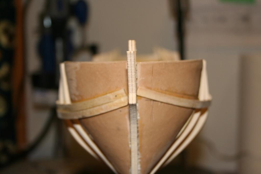
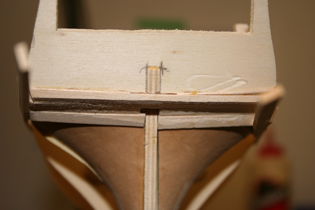
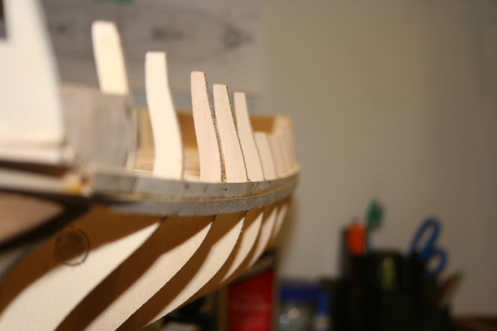
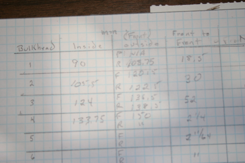
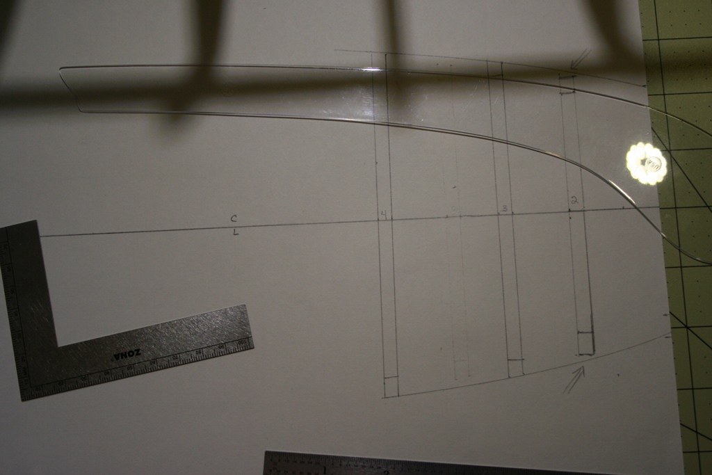
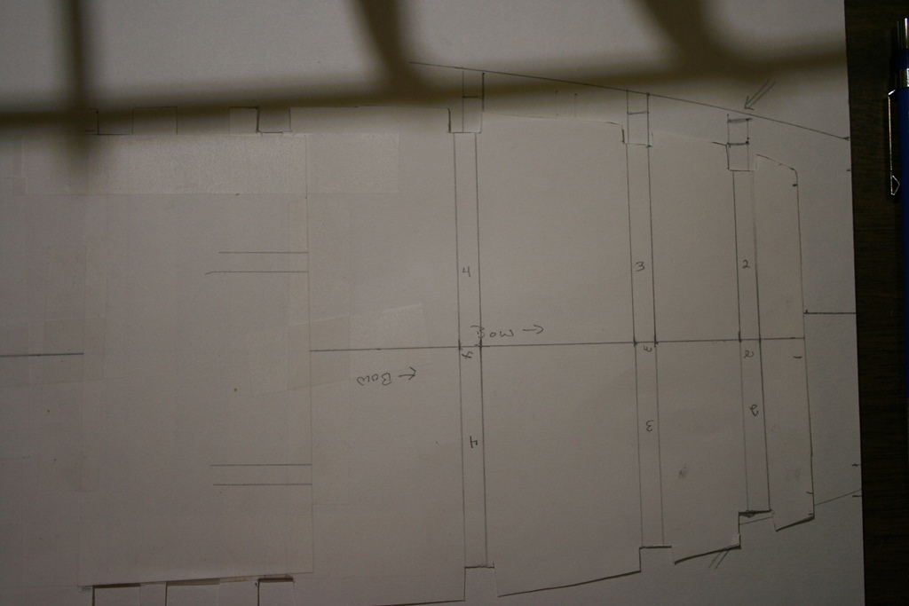
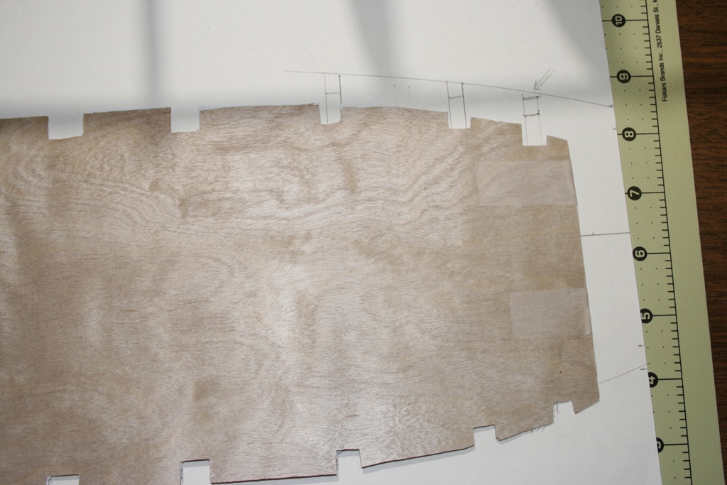
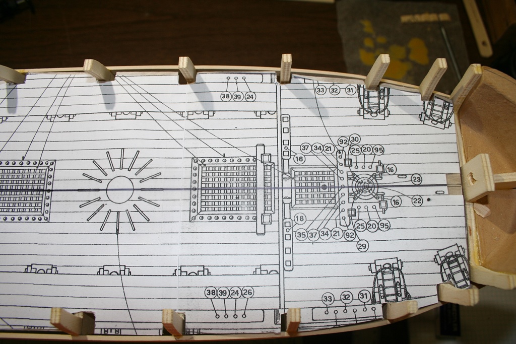
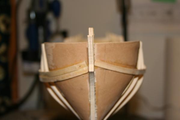
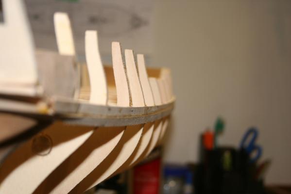
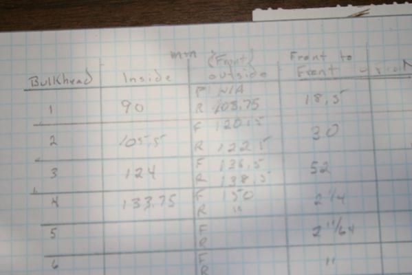
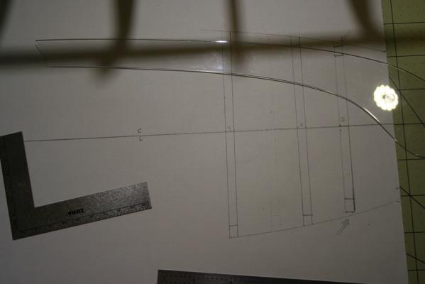
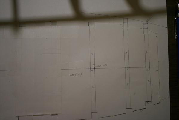
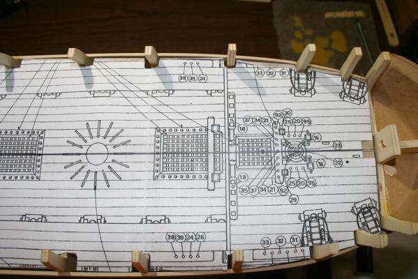
Wow - I had not realized that it has been over a month since I gave any update! Sorry about that! Have not gotten a huge amount done - my very special grandson has been here for the summer, so have been spending most spare time doing stuff with the boys. Between whale watching, Independence Day, the British Invasion and visits to other nations (Campobello Island, Canada), along with cleaning up from our hurricane, not a lot of time in the build yard. I have, though, made a small bit of progress. First, I have, indeed, gotten my first planks on the hull installed. Not the best looking, but since this will be double planked I am not terribly upset. View from bow - on (not quite in line, but follow the deck line nicely). View of stern (tough to see, but it is planked under there). View along the starboard side from the stern. I also placed an order with Bluejacket (local to me, so gave them a try) for some 1/64' ply for the false deck. Delivered in 3 days, very nice looking stuff. So, I started on the false deck. Since there were no good plans for the deck itself showing the bulkhead locations, I started by taking off the dimensions for each bulkhead (with great thanks to the Admiral, who lent her support to the cause). I captured the maximum diameter of each bulkhead (fore and aft face), the minimum width inside the hull, and the distance from fore of one to fore side of the next aft (all were the same thickness). Transfered these onto a large sheet of paper Faired the lines with a ships curve. Note the gap indicated at frame 2 - it exists with the first planks I put on. Verified the fit of the sheet into the hull after trimming out the bulkheads, then used this to shape and fit the plywood false deck. Once that was done, I then used the plywood to trim a printout of the deck plans - will use this to in turn place the various deck openings that need to be made in the false deck before I install it to the hull. So, that's where things are right now. Continuing to work the Essex for another month before switching back to the Emma C. Berry. Suggestions, observations, recommendations are always welcome!


-
Nice job, Max.
-
To do the Harriet Lane, starting with the hull downside up, I used calipers at each station to get the widths, then marked the midpoint off the rule. A bit of eyeball guided adjustment to align at bow and stern and drew the line.
-
Welcome back, sir, and many thanks for the update on your build - may take a bit of time for each stay, but dang they look good!
- 1,873 replies
-
- 1
-
-
- occre
- san ildefonso
- (and 1 more)
-
Nice work, Sal. The detail you are achieving on this bitty boat is most impressive!
-
Very interesting bit of data, Phil. Thank you for sharing that! Have been digging around on the Doughty cutters as well (starting when I found the Corel model of the USRC Ranger is totally fictitious!). I suspect, but have no proof, that the splashboards are actually a couple of separate construction items. The bitts there would tend to indicate an extension of solid framing timbers (knightheads) - would need additional strength to do the job there. The rest is likely solid planking (perhaps a bit heavier than normal bulwark planking would be) to both aid in diverting the spray since these cutters would have a tendency to want to ship water over the bow in a heavy sea, and also to provide stiffening between the bitts. Of course, that is all conjecture - but it seems reasonable given the way similar size topsail schooners were built at the time. There was no 1823 USRC Ranger (the kit name). I had a choice of several similar topsail schooners, but opted for the Detector. The Detector was built in 1825 by Fisher & Webster of North Yarmouth, Maine. She was stationed in Portland Maine for her career. I like the USRC Detector - my Admiral was an instructor for several years on Radiation Detectors, so thought it would be a good way to pay her some honors. I did some length on deck measuring on the two plans and worked the scale thing backwards to see how it worked out with Chapelle's descriptions. Using highly nautical terms, I measured the length along the centerline to the raised edge board thingies around the perimeter of the deck. I went to the closest 1/16". In "The History of American Sailing Ships", Chapelle says the Dallas was a sister ship to the Surprise built to William Doughty's 69'-6" plan (pg 194). I measured 17.25" on the AL Dallas plan and at 1:50, that would be 17.25 divided by .24 = 71.875'. If the scale were really 1:48 instead of the more Euro 1:50, the 17.25 would be divided by .25 = 69' which matches Chapelle's info more closely. On the Corel Ranger plans, I measured 10-15/16" to the perimeter board thingies. Dividing that by .1875 for the 1:64 scale, that ends up at 58'-4". On page 186, Chapelle describes the Massachusetts as being 58'-6-1/2". So the Dallas would be the largest tonnage and the Ranger would be the mid-size one based on the model plans, at least. I don't know if this is helps, but it was fun to open the boxes and look stuff over!
-
Glad to see you back online! The pictures post in somewhat of an arbitrary manner if you just upload them. What you can do is, after uploading said pictures, place your cursor where you want the photo to appear in the text and then click add to post next to the picture you want. Hope that made sense, but probably not.
-
The latest issue of the MSB journal is now available for download at http://www.modelshipbuilder.com/news.php This month's Table of Contents: Tidbits from the Past - Cats on Ships Model Ships of the Royal Museum Greenwich Shipwrecks of the World - the Steamship Beaver To Build a Hatch HMS General Hunter Proto-type Model—Part 3 Rijksmuseum acquires oldest known engraving of a herring buss The Book Nook - Ship Models: How to build Them by Charles G. Davis (1925) Badges: Heraldry of Canadian Naval Ships Gene’s Nautical Trivia Editor’s Page Note the following request from the Editor - she would be greatly pleased to have folks contribute articles to the journal. Great News! We will be starting our “One Eyed Willy” contest again in the September issue of MSB Journal. The contest will be run quarterly so we don’t exhaust the goodwill of those kind sponsors who generously donate items for us to use as prizes. Let me again make a request or two—if you enjoy the journal, spread the word among your friends and as always, I welcome any and all ideas, comments or articles. This journal has, and always will, depend on the readers to provide content. Do you have a favorite technique you use? Have you come up with a novel use for an item? Send it in—- if I get enough I can do a regular column on ‘tips and Techniques”, otherwise I can use them to fill in space at the end of articles. Please send your articles or ideas for articles to Winston@modelshipbuilder.com and put “MSB Article” in the subject line. Until next time, Ro
-
Like they all said - many happy returns of the day. Pictures?????
-
Give or take a stone.
-
Don - the weight is given in cwt, qrs and lb Hundredweight (cwt) Unit of weight, equal to 8 stones. 20 hundredweight to a ton. Quarter (qrs) Unit of weight, equal to 2 stones. 4 quarters = 1 hundredweight. Pound - avoirdupois (lb) Unit of weight, equal to 7000 grains, or 16 avoirdupois ounces. 14 pounds = 1 stone.
-
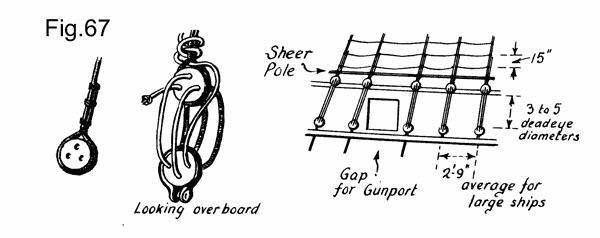
And I just KNEW that after hitting post I would find the reference! Here is some information from The Neophyte Shipmodeller's Jackstay by George Campbell (available from Model Expo and other sources). This is a great resource to have on your shelf! The shrouds are set up and adjusted by means of DEADEYES and LANYARDS. Start rigging them with the foremast on the starboard side. Seize (or bind) the first deadeye into a loop formed in the shroud. Fig. 67. Reeve (or thread) the lanyard through the deadeyes (you have already mounted the lower ones along the channel, Fig. 18.) according to the sketch in each case drawing the deadeyes together the distance given on your plan which may be anything from 3 to 5 deadeye diameters. Temporarily secure the lanyard in a hitch around the shroud end. It is finally secured by a hitch and a few round turns (you could glue this in place). Now run the free end of the shroud up through the lubbers hole, over the bolster, around the mast and down again to form the second starboard foremast shroud. Seiz;e a second deadeye into this end at the same height as the first one and all subsequent deadeyes similarly. When there is an odd number of shrouds on one side, the odd shroud is rigged on starboard, goes up and makes a full loop around the masthead and down the port side to form the odd shroud on the port side.
-
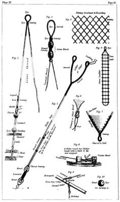
I can't find the reference at present, but recall that in general, subject to era and individual (rigger/captain's) preference, it was between 2.5 and 3.5 deadeye diameters between the deadeyes. Here are 2 diagrams - one from Steel (1796) and one from Biddlecombe (1848) that show part of the process and how the shroud and lanyard are reeved together. I'll see if I can find a better one with detail on reeving the deadeye. Hope these help!

-
In terms of the dimensions, I have come across quite a range - between about 20" and 32" in length. Interesting artifact recovered in the Great Lakes of a ramrod for a swivel gun that measured 14 inches long (the rammer, that is) with a 1/2 pound shot. Not sure who may have accurate period swivels - will do some checking when I get a chance.
-
Calculating the length of topgallant yards
trippwj replied to michaelpsutton2's topic in Masting, rigging and sails
According Sutherland in his The ship-builders assistant : or, some essays towards compleating the art of marine architecture, (1711), the top-gallant yards are 1/2 the top-sail yards. R.C. Anderson citre a similar ratio in his The Rigging of Ships in the Days of the Spritsail Topmast, 1600-1720 (1927). For French vessels during the 18th century, there is some interesting information in Marquardt's Eighteenth-century rigs & rigging (1992) where the top-gallant yard was 0.256 of the ship's length. He also offered that Chapman used 0.7 the length of the main topsail yard for the main top-gallant on Swedish ships, He provides a ratio of the fore and main top-gallant yard to the corresponding topsail yard of 0.690 from Falconer (1769) for all rates, and several possible ratios for English ships between 1711 and 1756 - ranging from 1/2 of the main topmast (1711), 3/4 of the beam (merchant ships, 1711), 5/17 of the topsail yard (1735) and the common 1/2 the topsail yard (several listings). These refer to proportions from Davis (1711), Sutherland (1711), Love (1735), Mountaine (1756) as well as Steel (1794), Falconer (1815 edition) and others. See Marquardt pages 33-36 for the various tables. Recalling always the vagaries of rigging at the time! These were somewhat more of a guideline - frequently not meeting the approval of a given builder or skipper and adjusted for personal taste.