


Roger Pellett
-
Posts
4,519 -
Joined
-
Last visited
Content Type
Profiles
Forums
Gallery
Events
Posts posted by Roger Pellett
-
-
Having lived in a backwoods Southeastern Ohio Community for the first half of my civilian employment I am struck by the difficulty that movie producers have realistically portraying the outlying settlements. Things that they often miss:
The aluminum painted tractor tire used as a flower bed.
One or more vehicles with the wheels removed “up on blocks” to be used for parts. Your shipyard could include a derelict car from which the engine has been salvaged for use on a boat.
A home freezer or refrigerator on the sagging font porch of the house. Doesn’t everyone keep one there?
Roger
- Old Collingwood, FriedClams, Canute and 4 others
-
 4
4
-
 3
3
-
Probably my ignorance of building codes but if you’re going to put up wood sheathing, why do have to mud and tape it?
Roger
- mtaylor, Keith Black, Canute and 2 others
-
5
-
There are several definitions of the term waterline. Two relate to this question. The first is the line defined by the locus of points between wind and water, ie the line at which the vessel floats. Gravity makes this line straight but not necessarily parallel to the keel. Changes in loading; cargo, fuel, stores, etc can change both the level at which she floats (her draft) and the angle at which she floats (her trim).
The term as it relates to paint schemes really is more applicable to vessels where draft and trim do not change; think yachts. Classic yachts and I believe most modern warships are usually painted with a straight waterline taken from the Naval Architect’s design drawings.
The “waterline” on commercial vessels is just the border between the owner’s chosen topside color and the bottom paint because draft and trim depends on the cargo they are carrying and how it’s loaded. Here on the Great Lakes in the past it was common to run the topside paint all the way down to the top of the bilge strake. As this strake curved up at both the bow and stern, the border between it and the bottom paint followed this curve. The draft of these vessels could vary widely wether loaded with iron ore coal, or ballast water.
It is quite possible that Titanic’s “waterline” curved because it was following a particular plating strake
Roger
- Dan DSilva, Kelp and mtaylor
-
3
-
I see that a number of these vessels were built by The American Shipbuilding Company. Bowling Green State University (Ohio) holds American Shipbuilding’s drawings. They should be able to supply copies. Originally, the names of these vessels all began with “Lake.” So if you enter a known name into the data base it will yield the original name. You can then use this to search for drawings.
Suggestion: the Poker Fleet vessel King was built by American Shipbuilding.
Roger
- Canute, mtaylor, FriedClams and 2 others
-
5
-
Post 249:
The thing on the left appears to be a tank with a bolted clean out/ manway. It could be for fuel or lube oil. I’m wondering if it might fit alongside the oil drum on the rack. OR- it could be a condenser scrapped from a repaired vessel; quite possible with the large manway. Every self respecting industrial facility needs a pile of stuff not good enough to use but too good to scrap!
Roger
- Old Collingwood, Egilman, Jack12477 and 6 others
-
9
-
My wife and I visited the Kennedy Space Center some 20 years ago. I don’t know what has changed since but back then it was a wonderful visit. The visit was based on a structured tour. A bus took us from the visitor’s center to one of the launch vehicle assembly buildings. Inside was a Saturn Rocket that had been painstakingly restored; huge and impressive! We were then shepherded into the next room that was set up with bleachers. They reenacted an entire moon landing from conception to walking on the moon. Even though it was simulated it was quite effective. Much better than all of the hoopla at nearby Orlando.
If you have a chance to visit do so.
Roger
- Egilman, Jack12477, Old Collingwood and 3 others
-
6
-
Most common soft solders melt somewhere between 600-700F. This isbelow the temperature required to anneal brass.
- mtaylor, Dan DSilva, Keith Black and 1 other
-
4
-
IThe “Lake” class of steamships were steel hulled vessels built by shipyards along the shores of the Great Lakes. Over 75 of these were built in Duluth, Minnesota’s Riverside neighborhood along the St Louis River that flows into the Western End of Lake Superior. In addition to constructing the shipyard the owners built an entire community; apartment buildings, houses, recreation clubs, etc. The houses are still lived in.
The Ships were based on the Norwegian Fredrickstad design with dimensions limited for passage through the Welland Canal around Niagara Falls and the locks around the rapids in the St Lawrence River. This limited length to about 240ft. Most if not all were not completed in time to stem the WW I shipping crisis. Construction stretched into 1920, and of course they then contributed to a glut of shipping that depressed prices. The Riverside Yard closed shortly thereafter. The yard’s owners formed a Great Lakes fleet composed of these vessels. Known as the “Poker Fleet,” the Ships were named Ace, King, Queen, Jack, and Ten. In the first picture that you posted above Corsicana’s cargo gear has been fitted out for the lumber trade.
You should be able to find drawings. The American kit manufacturer A.J. Fisher used to sell a kit and drawings for one of these.
Roger
-
Can’t help with kits, but artillery, shipboard armament, gun founding, etc is a highly technical subject by itself and separate from ship modeling. Different countries’ armories produced guns of their own design, and of course, ships could be armed with whatever was on hand including captured guns. The 1776 Gundalow Philadelphia recovered from Lake Champlain and displayed in the Smithsonian Institution was found to be armed with Swedish guns. Where did they come from?
So, it would seem to depend what you are trying to do. If you are just trying to dress up your cross section with a cannon, any gun of the correct period and scale should work. If you are trying to model a specific situation you need to do lots of research. If your model is French, check out the Ancre Publications,AND no brass cannon balls. Also, the Carronade was probably cast iron.
Roger
-
As wooden parts get smaller, you start fighting the grain. When that happens, I like to use brass, readily available in rod and sheet. In both cases smaller diameter and thinner than any wood. In your case, brass rod looms with sheet brass blades soldered on. Paint the finished oar.
Roger
- Dan DSilva, mtaylor, Keith Black and 1 other
-
4
-
-
Also, keep in mind that solder is not good at bridging a gap between two pieces of metal. It works best if the pieces are lapped tightly together, particularly in conjunction with a low viscosity liquid flux. Applied with a small model paint brush, this flux seeps into tiny openings between the pieces to be joined. When the joint is heated solder is drawn in.
Roger
- robert952, mtaylor, Ryland Craze and 2 others
-
5
-
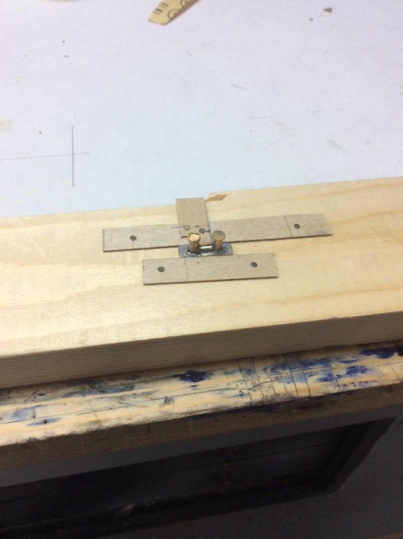
Here is an example of a setup for soldering using thin craft plywood to hold parts in place.
The problem: When soldering the reinforcing bar spanning the two bollard posts, the soldering iron pushes the bar out of alignment.
Solution: The two longitudinal strips secure the base while the “tongue” backs up the reinforcing bar. This is a very simple fixture. Much more elaborate ones can be created. This is the cheap craft plywood, not the more expensive aircraft quality. I also have a large supply of 1/2in and 3/8in nails that I inherited from my father who built a fabric covered wooden wing for an EAA group project. While I don’t use these on my models, I use them all the time for making soldering fixtures.
Roger
-
-
Another maybe not helpful comment.
my current project requires extensive soldered brass fabrication, and I don’t find “ helping hands” to be useful. The concept behind this tool is to suspend two or more parts in three dimensions for soldering or other work. The problem is that pressure from the soldering iron can easily knock the parts out of alignment.
Instead, I prefer a 2-D approach where the parts are secured to a solid backing. This can be wood, plywood, or aluminum. Parts can be affixed with aluminum wire, tiny coated steel nails, or even masking tape; anything that you have in your shop that solder won’t stick to. Sometimes I use plywood “springs.” This is a strip of thin plywood with one end nailed to a thicker piece of plywood. The end not nailed captures the part. This system is not quick. It’s possible to spend 2-3 hours dreaming up and building a clamping system for 1 minute of soldering.
Roger
- VitusBering, Canute and mtaylor
-
3
-
Dan, I re-posted it. Look below under tips.
Roger
-
Steven,
I have long assumed that the grapnel hanging from the bowsprit was used in battle. Maybe to drop and hook onto an opponent? If that is so, would the sprit sail be set when the grapnel was used? Wouldn’t they shorten down to “fighting sail”?
Roger
- Keith Black, Glen McGuire and mtaylor
-
3
-
Actually my suggestion was three locations in rotation- East Coast, West Coast, Midwest, but the same city, venue, etc. each time in each. One reason for this is to make life easier for volunteer committee members.
Annapolis would work. It is close to three major airports and the Naval Academy Museum is an obvious draw. Unfortunately it is no longer the quiet Naval Academy town that I used to like to visit.
Newport News/ Norfolk is of course rich in maritime history. If you include the Norfolk Naval Shipyard it has the most to offer of all three. Not close to a major airport and I’m not sure if it would appeal to spouses.
Roger
- mtaylor and Ryland Craze
-
2
-
I personally would attend a NRG Conference in Mystic on a regular basis:
A beautiful hotel.
A town that my wife feels comfortable exploring while I attend the meeting.
There are always enough new things happening the the Seaport to keep me coming back.
Other things to see nearby- Submarine Force Museum, Coast Guard Academy.
Good restaurants
A reasonable drive to Herreshoff Museum
Accessible to NYC LaGuardia Airport with nonstop flights to major Airline Hubs
Roger
- druxey, dvm27, Ryland Craze and 3 others
-
6
-
I’m probably the very last person to suggest anything using computers,BUT could you make a color copy, or scan of the old decal sheet and then print it on new decal paper?
Roger
-
The Lift method is just another name for the Bread and Butter method.
Regardless of how you eventually decide to build the hull you need better drawings. So, if you are set on using the drawing that you have you need to make a traditional lines drawing with regularly spaced waterlines, body plan sections and probably several buttock lines. This will ensure that your frames will all line up and a fair (smooth) hull will result. From this you can Loft additional structural elements like frames.
Roger
- FriedClams, goatfarmer11, mtaylor and 2 others
-
5
-
An interesting model! I’m curious about the black smoke plume on the box. Has the guy in the foreground been trying to shoot down his squadron mate in the background?😆
Roger
-
The gage is better for me because:
I avoid CA glue like the plague.
There is no concern about mashing the threads with the caliper
When it comes to rigging I am of the “If it looks right it must be right School”
There is actually some justification for the last comment. Many years ago in the Nautical Research Journal there was an article about rigging by a noted expert modeler. He commented that based on what the eye perceives slightly under scale rigging provides a more scalelike appearance. So, I measure within the limits of my gage and then select the closest line that looks right on my model.
Roger
-
National Park Service- That’s sad but that seems to be the way things are today. Sort of like “Your call is very important to us” before they place you on indefinite hold.
Roger
- mtaylor and Keith Black
-
2


painting bulwarks red, why?
in Building, Framing, Planking and plating a ships hull and deck
Posted
Barn Red ( iron oxide) paint still is cheap and is widely used as an industrial primer.