


bartley
-
Posts
406 -
Joined
-
Last visited
Content Type
Profiles
Forums
Gallery
Events
Posts posted by bartley
-
-
-
I have done this on 2 mm brass rod with a good success rate. My technique was:
1. I used a mill to ensure the hole was vertical.
2, I used a V bar and centered the drill bit on the V before clamping the rod into the V
3. I used a Kyocera bit as they a very sharp
4. You can file a very small flat on the side where the drill will enter but I did not find this necessary.
John
-
I agree with those who say not to glue the mast at all. However, in most cases there is quite a deep slot cut into the bulkhead under the mast which should set the rake quite at least approximately,. As you tighten up the rigging you still need to check th alignment I used to use a plumb bob but always found this a real PIA as it starts to swing on the slightest movement. I now use a laser level (quite a cheap one). I set it up about 1 m from the ship and it does NOT move and it projects a cross so that you can adjust the deck to match the horizontal line and the mast to match the vertical line. For the rake you can use a jig to tilt the ship forward by the correct amount and use the laser level again.
John
- HardeeHarHar, mtaylor and John Ruy
-
 3
3
-
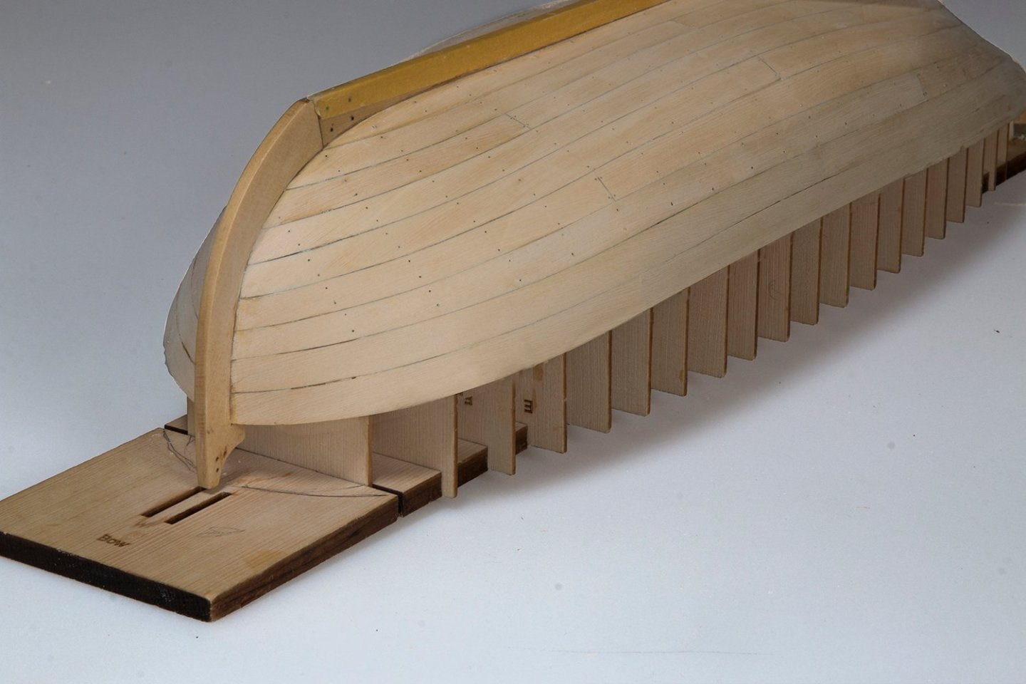
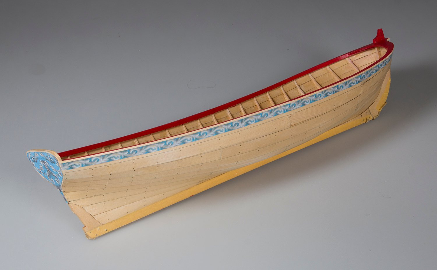
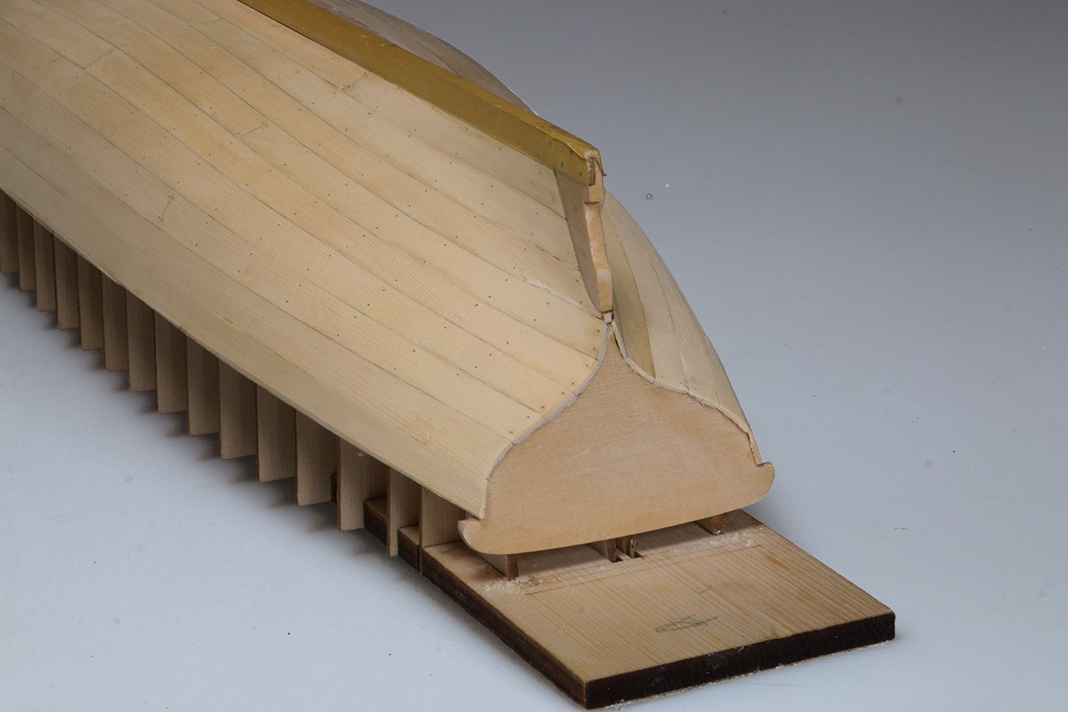
The Wales are now installed and sanded back for and aft as recommended by Chuck.:
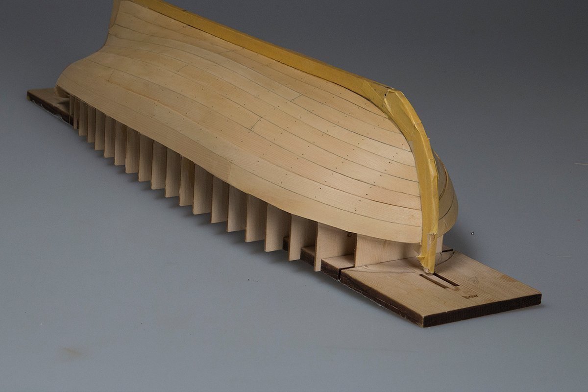
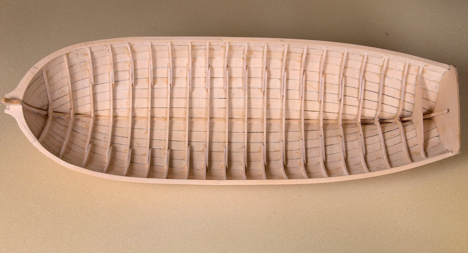
When the hull is inverted and the build board removed it looks like this:

The removal of the frames was quite straightforward . However there is way too much seepage of glue into the interior of the hull . This is the first time I have used CA to fix the planks. I clearly overdid it. I was a little unsure about the faring and wanted to ensure that the planks were secure. I needn't have worried as the fit was pretty good in fact.
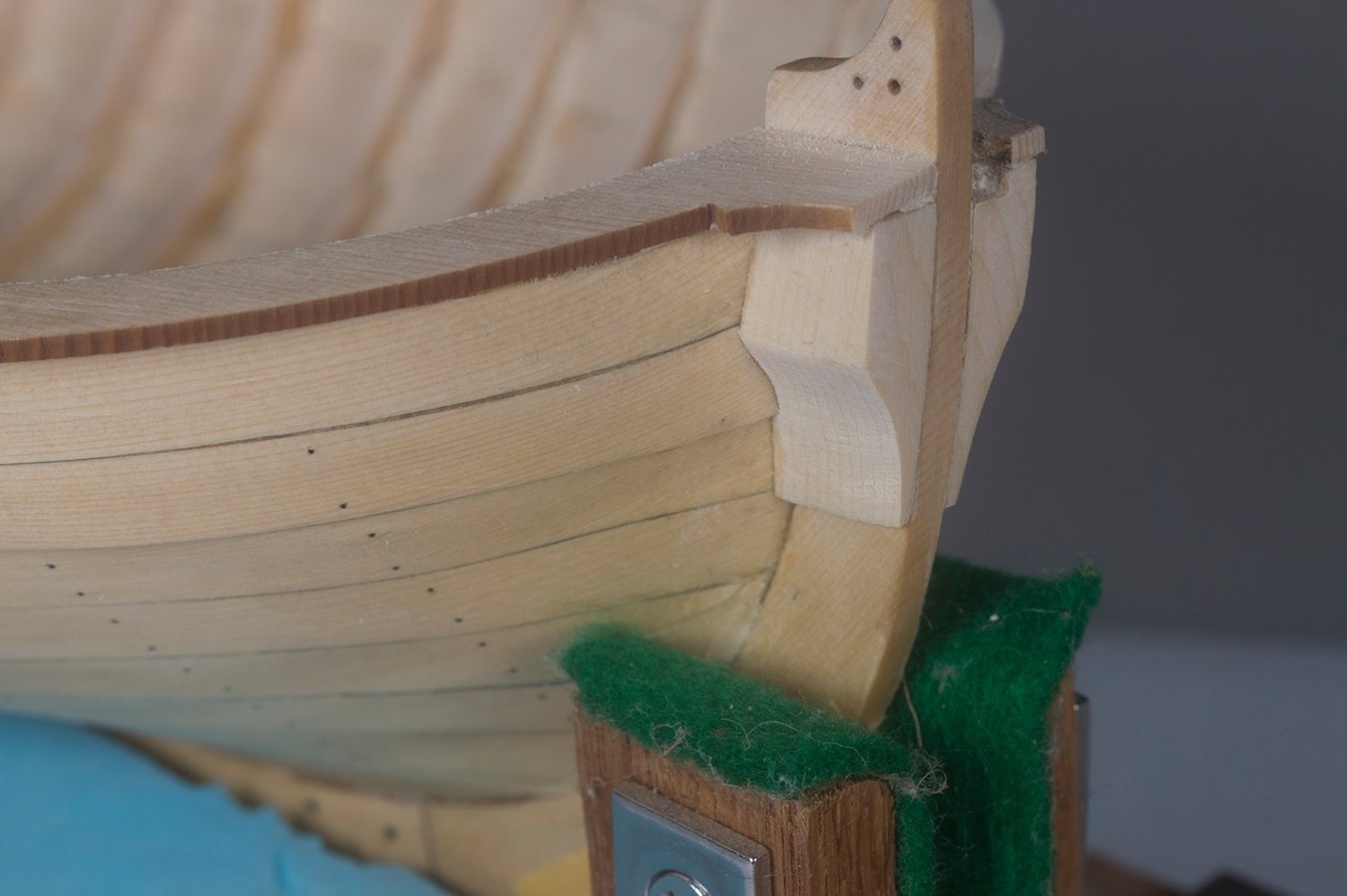
The cap rails were then installed leaving plenty of meat on either side for sanding to shape:
Next the bolsters at the bow were fabricated and fitted. A tricky little job this one. Chuck provides six blanks and I used five to get two satisfactory ones:
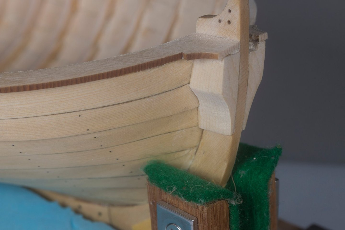
The next task is to fair the inside and narrow down the cap rails significantly.
John
- Chuck, rlwhitt, JacquesCousteau and 5 others
-
8
-
-
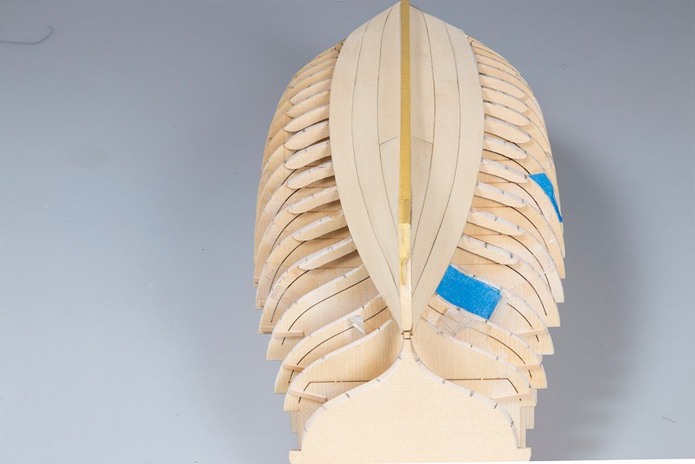
Planking completed
I have all nine planks on now but the wales are still to be installed. It looks a bit "blotchy" because I gave the first five planks a coat of Wipe On Poly and when I sanded back some of it remained. It will be more uniform when I apply I final coat
I am also a bit shy of the top of the frames amidships (by a little under 1/32). I could see that this was happening throughout the planking. I think maybe I did not fare quite enough in this region. Anyway I was proposing to address it by making a slightly wider second Wale

John
- robert952, Diver, JacquesCousteau and 7 others
-
10
-
Planking begins:
I have three strakes in place now. I damaged the end of one garboard and had to make a new one. Mine was not quite the same as Chuck's laser cut one so the was a little asymmetry between the sides but I think I am pretty close to my tick marks now so I am reasonably happy but it is nowhere near the quality of Chuck's high standard.
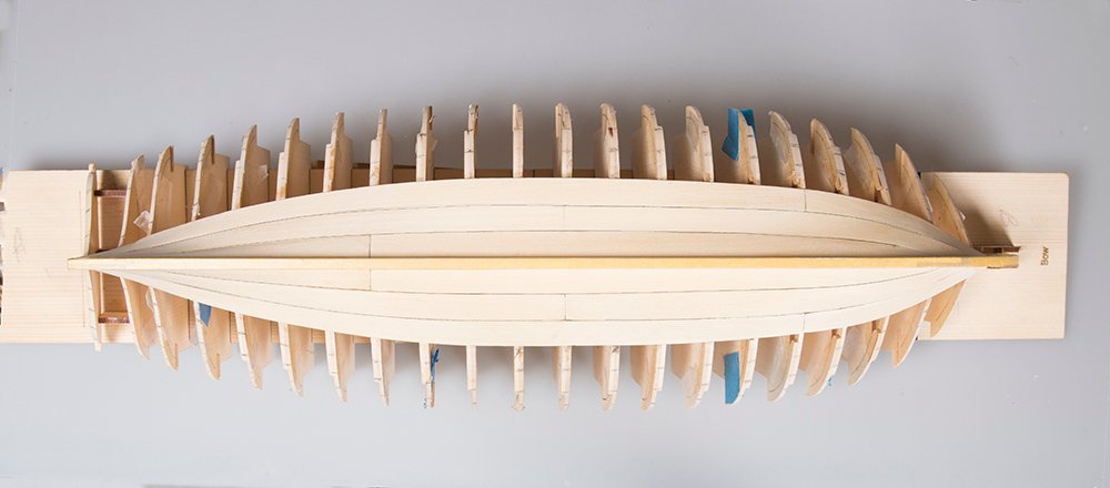
I am thinking that I might start the simulated nails now while I can see the frames clearly. Would I need to do light sand before attempting this? The planks are pretty thin so care would be needed. What to do people think?
John
- mgatrost, Ryland Craze, JpR62 and 5 others
-
8
-
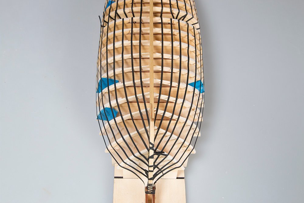
Completing the lining out
This is quite a time consuming process but, as Chuck says, this process will be a good check on the process of planking and is good practice for future projects. It is now complete and as a check I found that it followed Chuck's templates quite well
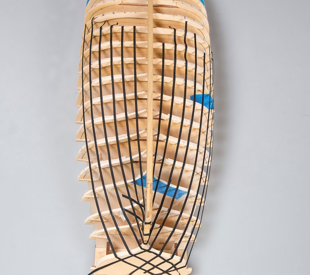
It might be a while before I start on the planking as my other hobies need to take prcedence for a couple of weeks.
John
- ccoyle, JpR62, Ryland Craze and 8 others
-
11
-
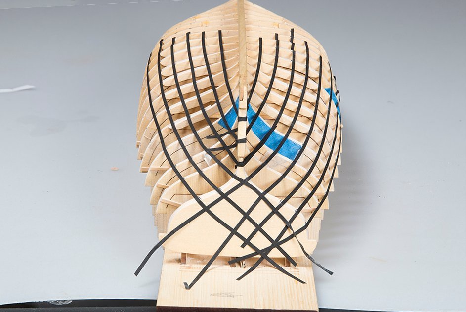
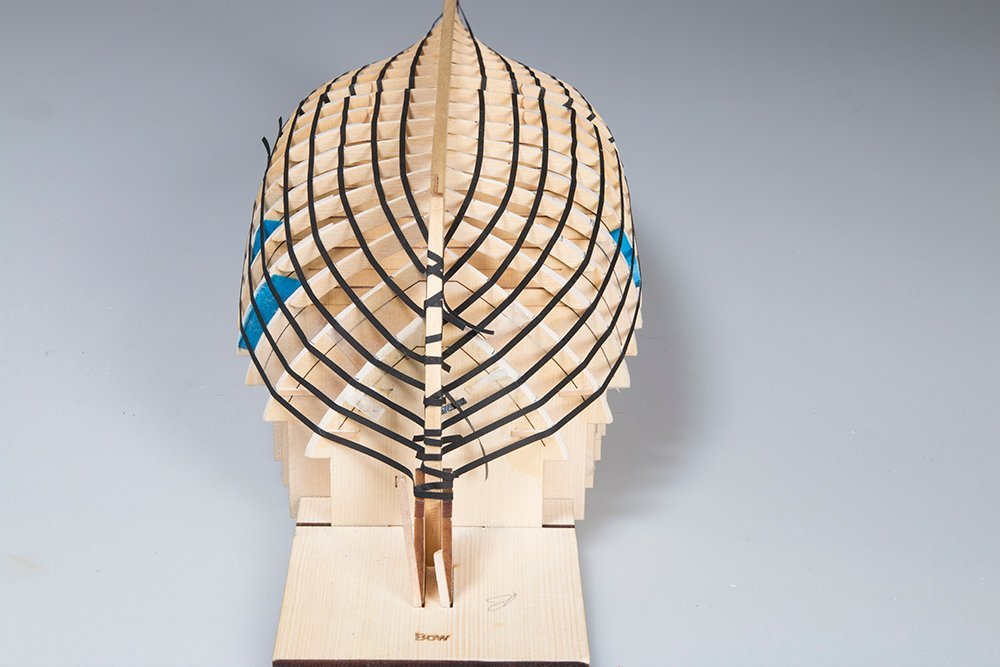
Lining Out the Hull
Perhaps not strictly necessary here but it is an good to practice this important part of the planking exercise. I have started at the stern and here is what it looks like so far:
The distortion in the photograph makes it look as if the planks deviate amidships. They are in fact quite parallel at this point. I also found that some of my tick-marks were a bit out so I will adjust them once I am happy with the lining out.
John
- JeffT, Ryland Craze, Diver and 3 others
-
6
-
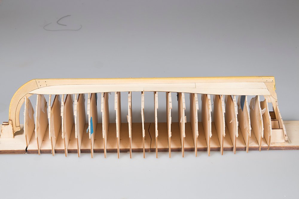
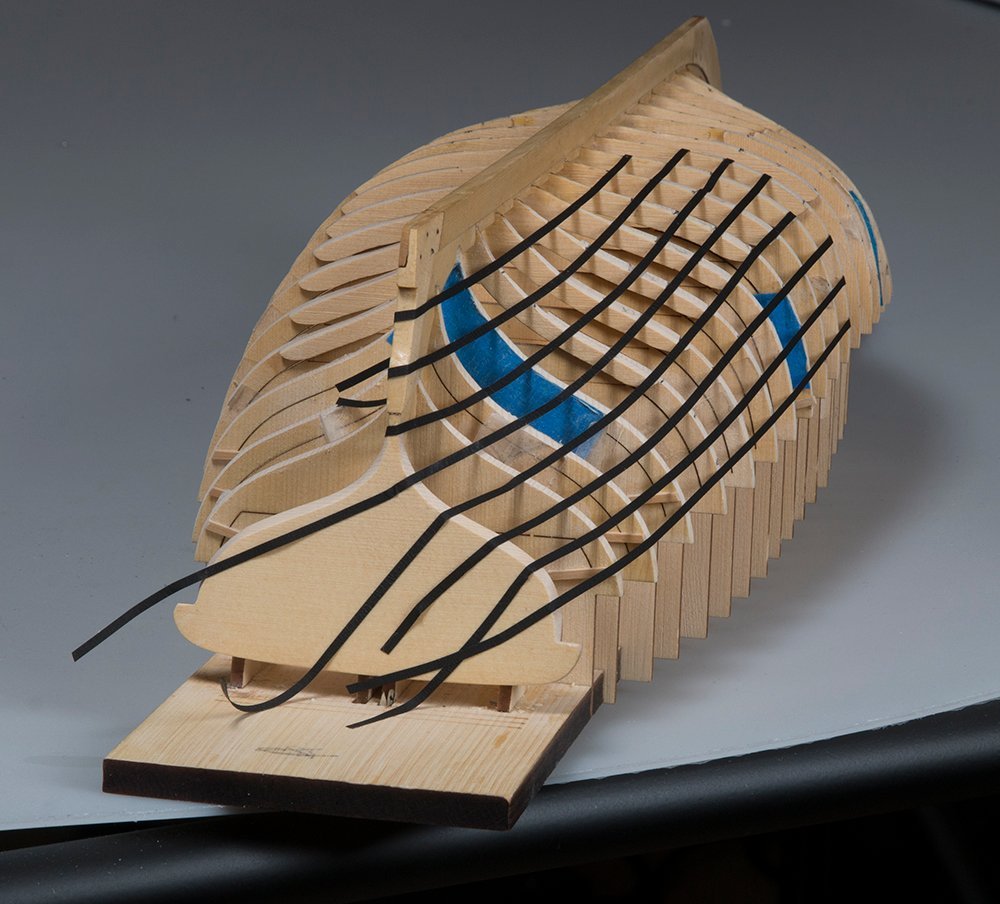
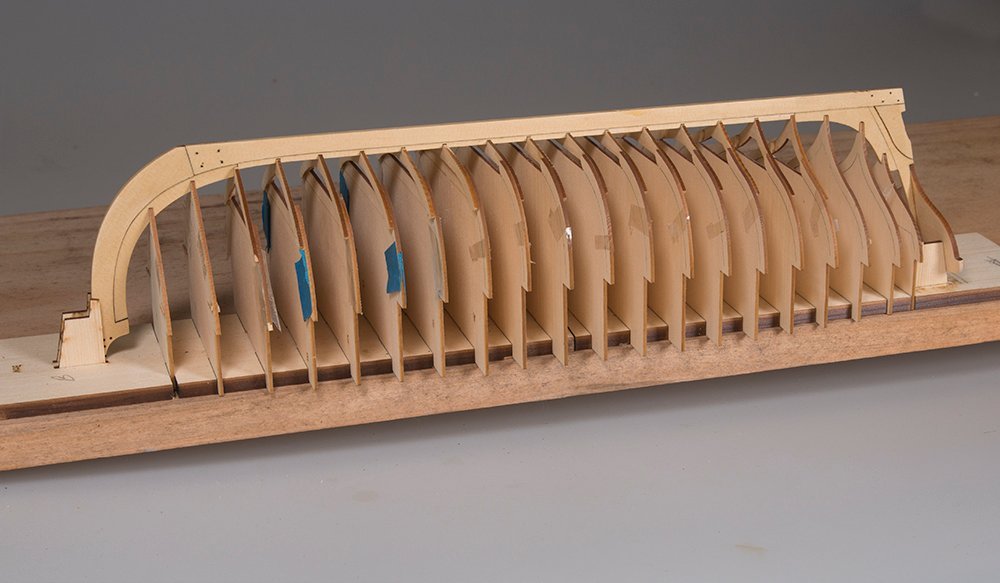
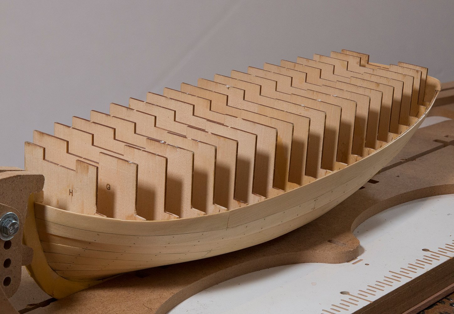
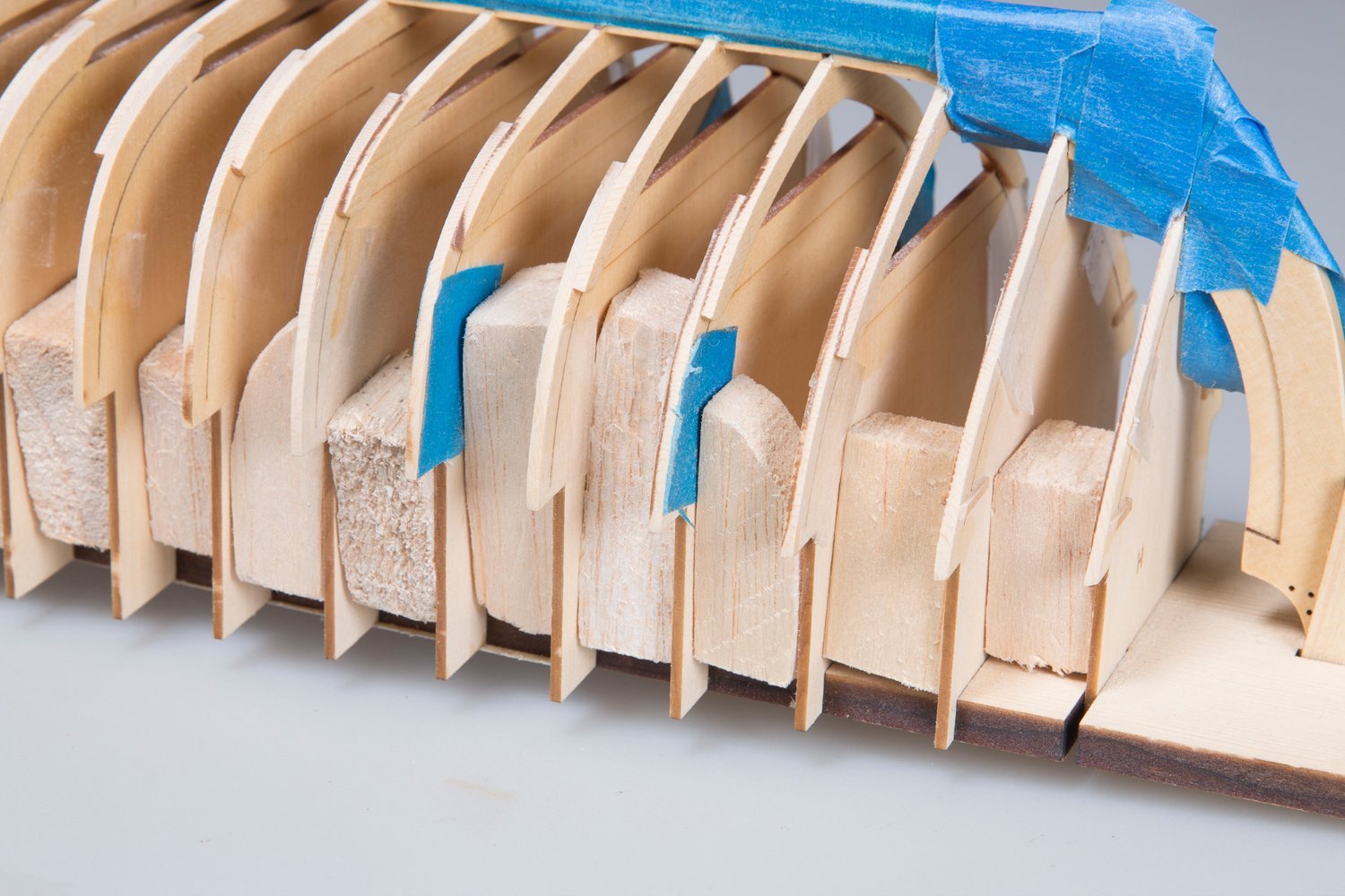
Frames Attached and Fairing Begins:
The frames are now glued in place
I then commenced with fairing the frames. These frames are very delicate (1/16") compared to ships that I have builtin the past so I was a bit tentative. You can see from this photo that I added some balsa blocks between the frames as a safety measure:

However, when I showed this photo to Chuck he advised that I had a way to go and that I needed to keep going until the laser char was removed. So here is where I am at now:
John
- JeffT, Diver, Ryland Craze and 5 others
-
8
-
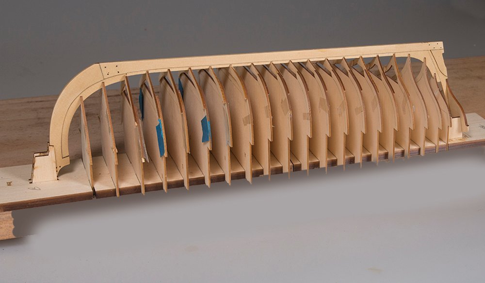
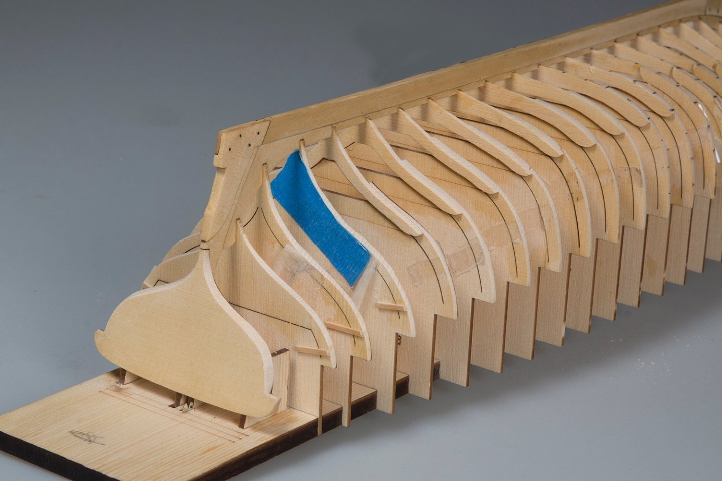
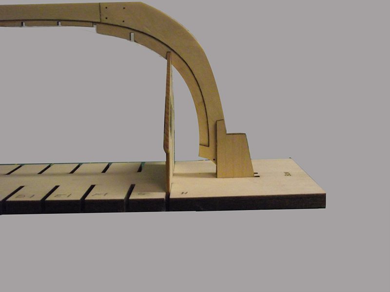
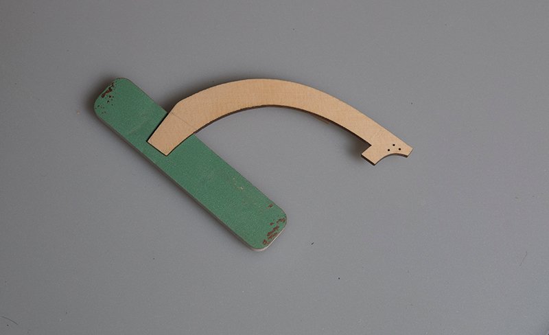
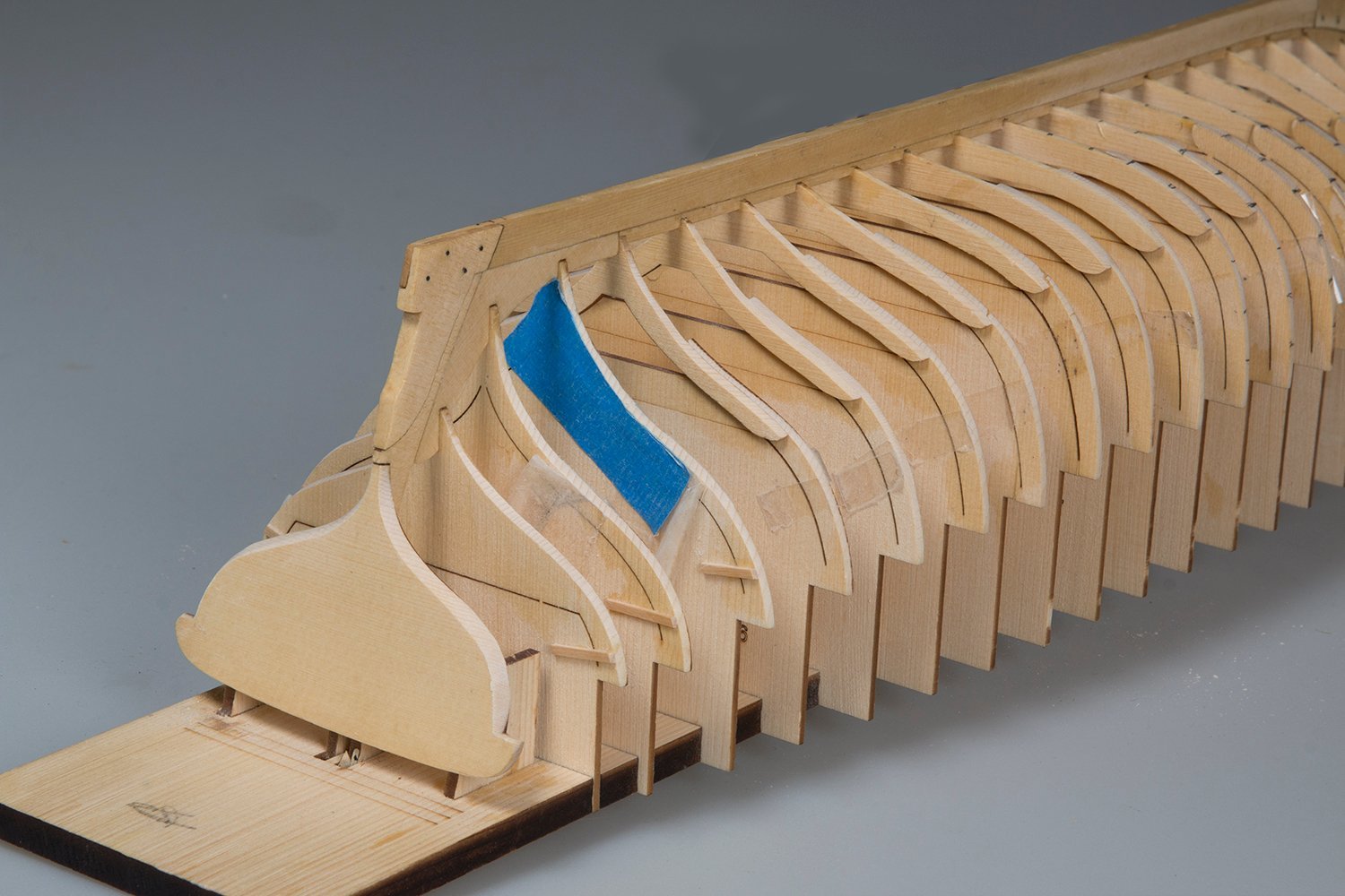
The transom and installation of the frames:
The transom needs to be installed perpendicular to the keel. There is a slot cut into the frame so the "vertical" alignment is accounted for but to ensure it was perpendicular ro the keel I made this simple jigand clamped the trasome otself to this:
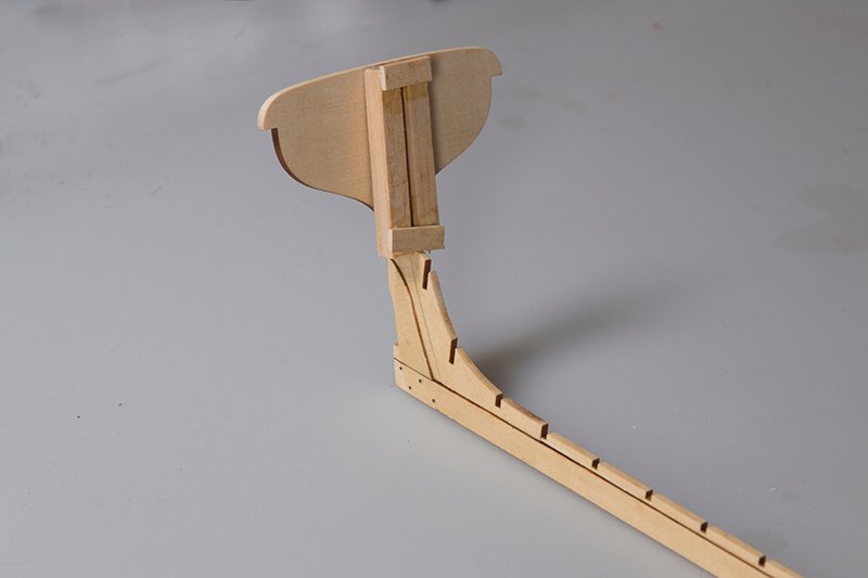
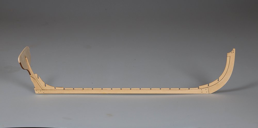
Time to install the frames there are two types - two in the bow ( G & H)and three in the stern ( 10 , 11& 12) are flat one piece frames. These are installed onto the baseboard first and the keel dry fitted to these.
The remaining frames are "double" with a floor piece glued to each frame
These frames are the each dry-fitted to the keel and the alignment checked. Each was found to be perpendicular to the baseboard with no adjustment needed
John
- JpR62, robert952, Ryland Craze and 4 others
-
7
-
On 6/3/2023 at 10:19 PM, glbarlow said:
Nice to see you back at it again.
Thanks Glenn,
Yes, my other hobbies took up some time plus a commissioned non- ship model. This looks like and interesting model. I have never built an upside-down model like this. Fairing could be a challenge as the frames are only 1/16" wide!
Regards,
John
- glbarlow, Ryland Craze and robert952
-
3
-
7 hours ago, Chuck said:
Excellent start...enjoy the project!!! Its so good to see another get started.
Thanks, Chuck.
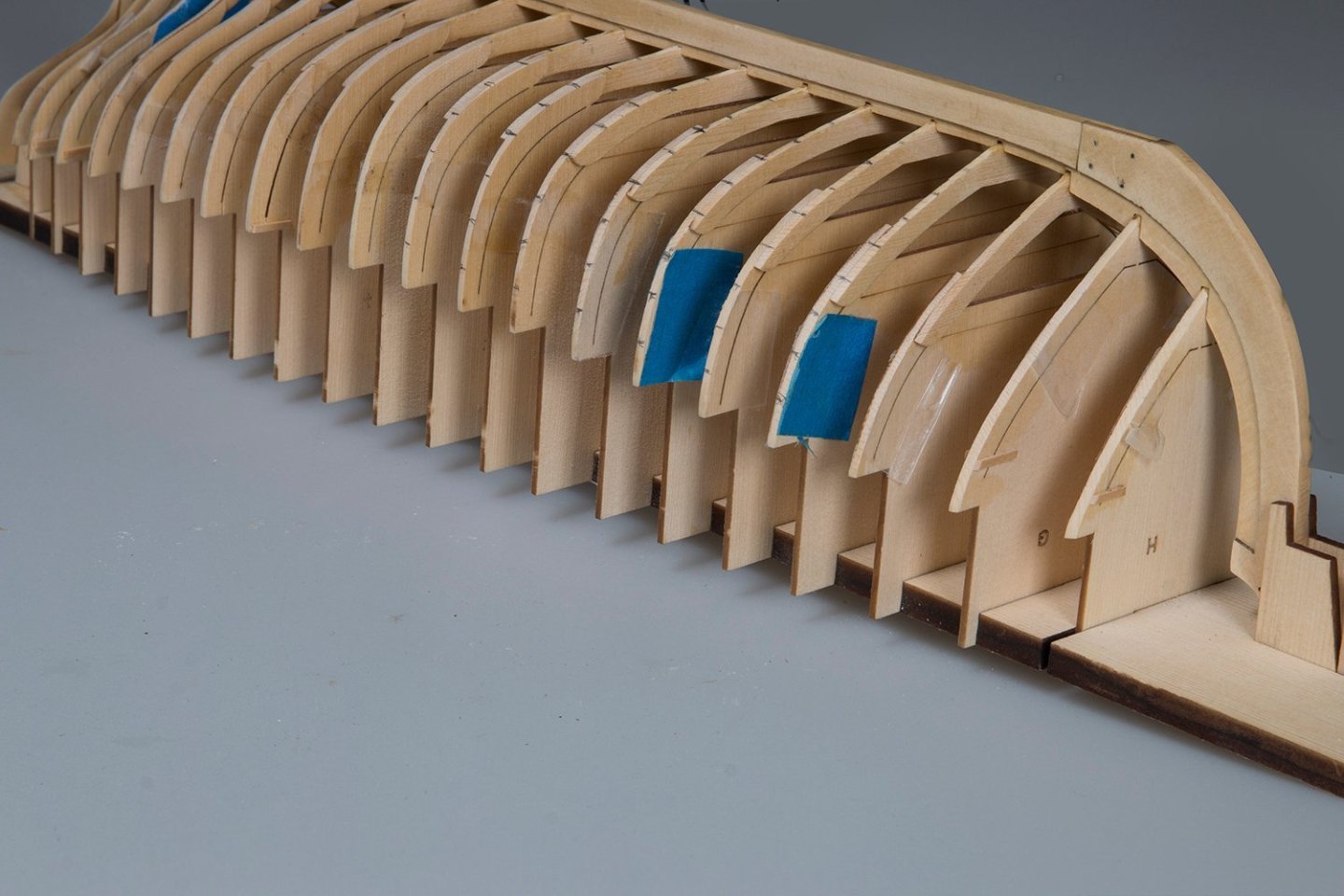
It never ceases to amaze me how well designed your models are. I have just dry fitted all the frames. Not only to they fit perfectly in the slots but every single one is dead vertical. I checked with my square!!
I hope I can maintain this perfection when I finally glue them'
John
- Chuck, glbarlow, Ryland Craze and 1 other
-
4
-
9 hours ago, Ryland Craze said:
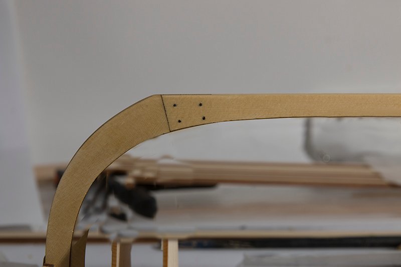
Nice start. It is good to see another Medway Longboat being built. Also, do not forget to install the simulated bolts on the keel at the stern.
Thanks, Ryland. Yes I have done the bolts fore and aft and both port and starboard. I didn't take the right final picture really.
John
- robert952 and Ryland Craze
-
2
-
I am starting another of Chuck's builds today and am excited as I have never used this method of construction before.
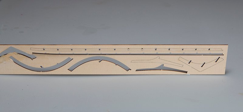
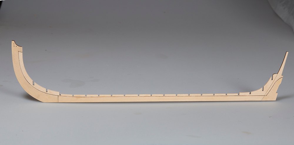
The first task is to construct the keel. There are two versions - one with scarf joints and the other with lap joints I am going to build both but hope to use the one with the lap joints. Here are the laser cut sheets involved:
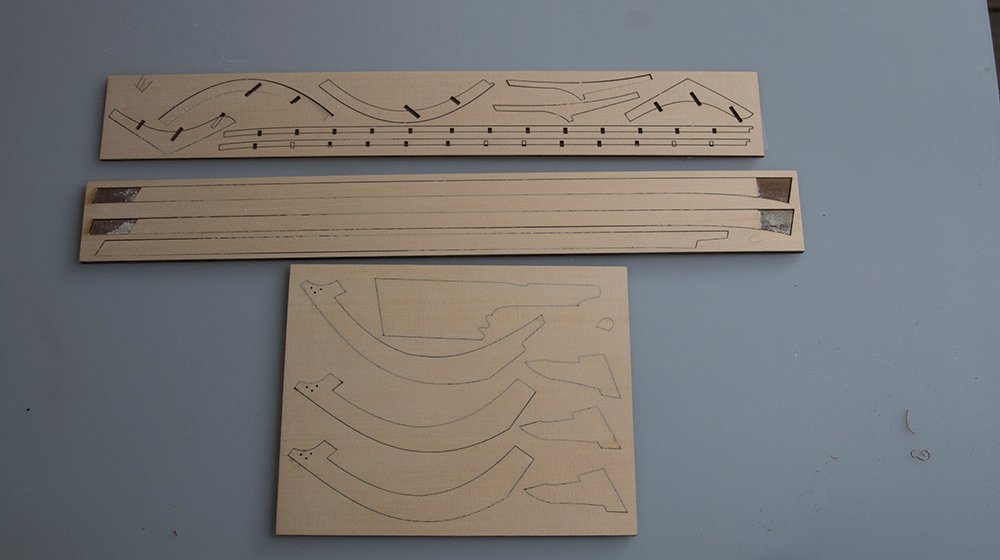
The Scarph version is quite simple:
The lap joint version is more challenging. I started by paring away the joint with a sharp blade and then once close the required depth I finished it off with one of these sanding blocks which have sandpaper on the top only and not on the sides
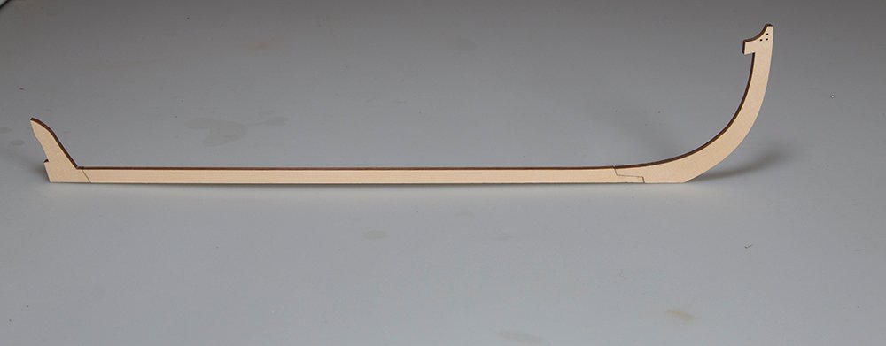
and the two joints assembled:
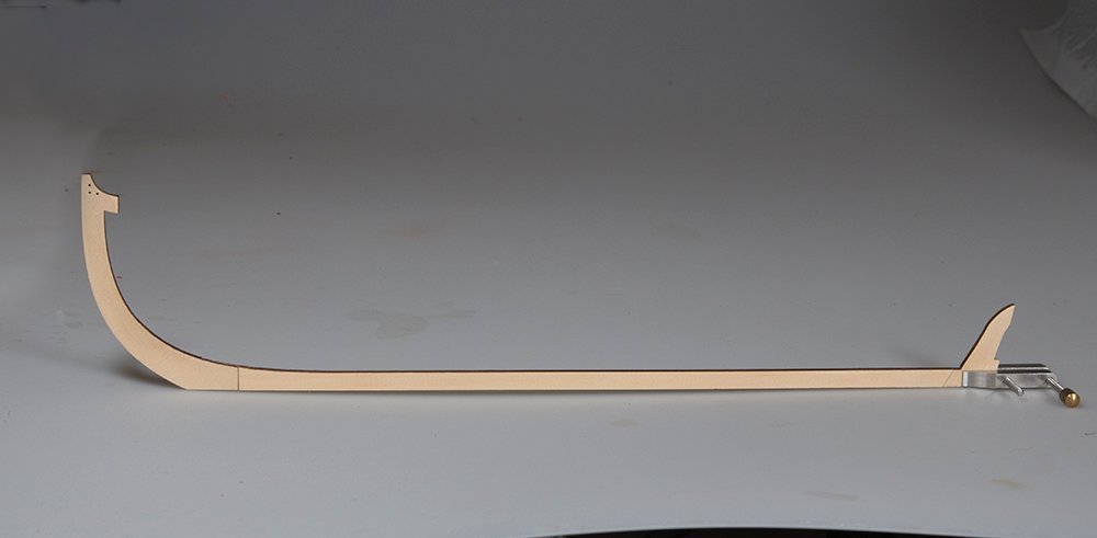
The two versions are shown here:
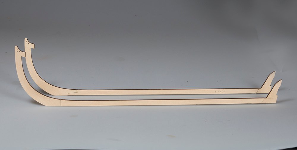
The lengths were identical so I concluded that the lap joints were OK. The parts for the notched keel pieces are nicely etched on the following sheet
Bolts for the lap joints are simulated with black monofilament:
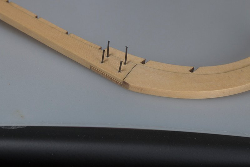
These are then trimmed flush with the surface.
After a coat of poly the completed keel looks like this:
John
- Chuck, Ryland Craze, Dave B and 5 others
-
8
-
Thank you guys for your kind comments and for all the "likes".
It is back to ship building after this - possibly Chuck's Medway Longboat , though it is unavailable at the moment.
John
- mtaylor, Old Collingwood, Egilman and 2 others
-
5
-
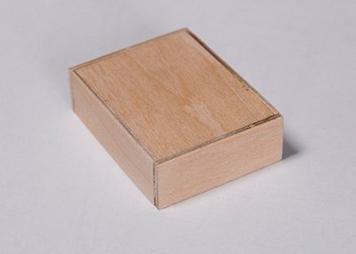
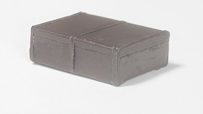
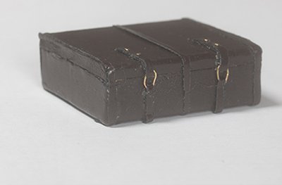
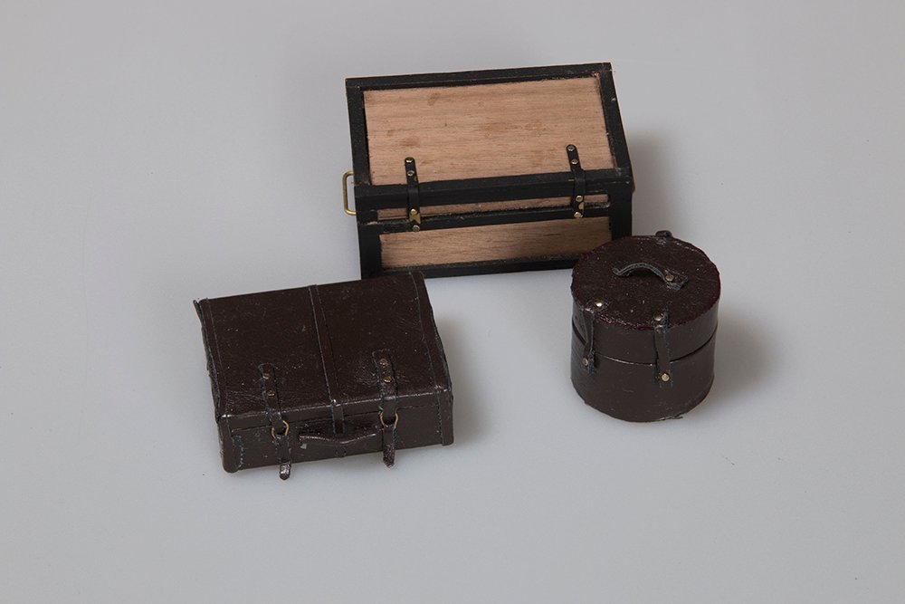
Luggage and final tweaks:
A few Items of luggage such as a suitcase, a trunk and a hatbox were all constructed in essentially the same way. A wood frame was constructed and then ech was covered with dark brown Nappa. Hinges and detail were added an the items placed on the roof rack.
=
.jpg.31a4d1c1c1e22490fe82f4a742b1b844.jpg)
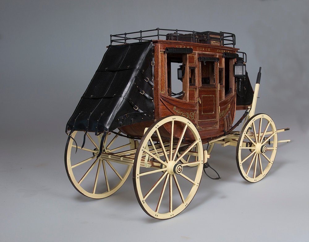
And now the completed model:-
Thanks for all the "likes" and comments during the course of this build.
John
-
Thank you, Bob and Kevin for your kind words. Just a bit of luggage to go on the roof and then its complete.
John
- Old Collingwood, BobG, Egilman and 2 others
-
5
-
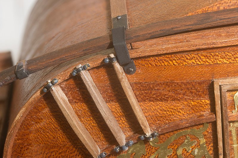
Attaching The cabin to the chassis:
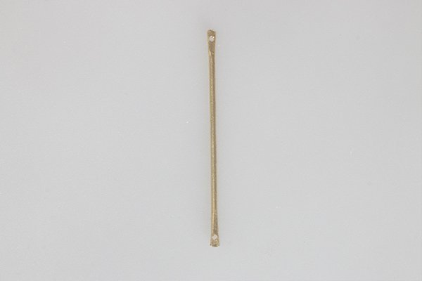
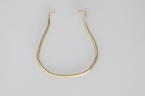
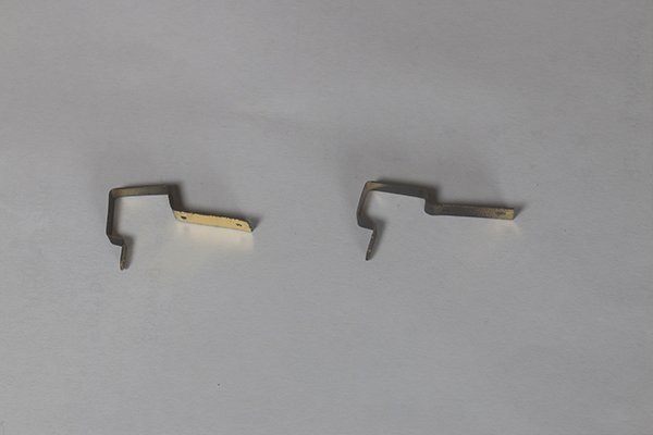
Before the chassis is attached the mounting steps need to be constructed and attached. These have several components all made from 1.5 mm brass tubing:
.jpg.1b1bf1d4973712678cc5ead1c8a9e0c9.jpg)
The upper (straight part is bent to shape as shown in the last picture. The lower part is bent into a U shape/ All the parts are drilled with 1 mm holes so that they can be held together by the brass plate as shown in the third picture. A step is glued to the loerer part and the whole assembly attached to the under the cabin like this:
You will also notice a strengthening strap made of 3mm brass strip has been added. The Idea of this somewhat complex arrangement is that the lower step could be folded up when not in use.
As yo can see the cabin needs too be mounted upside down in order to attach the chassis. The method of attaching the simulated leather suspension can be seen here:
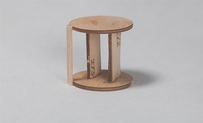
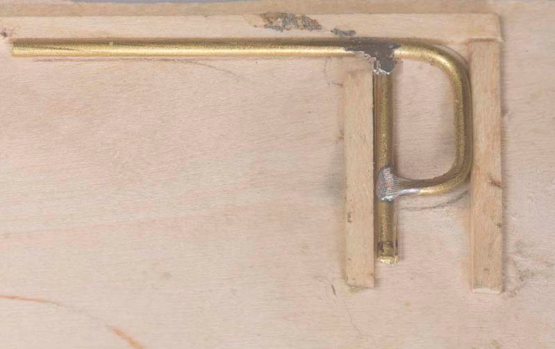
Before the front part of the chassis is attached, the Whippletrees are assembled. For those who do not know what these are they are attached to the draw-bar and are designed to spread the load of the horses. The method of fabrication is shown below:
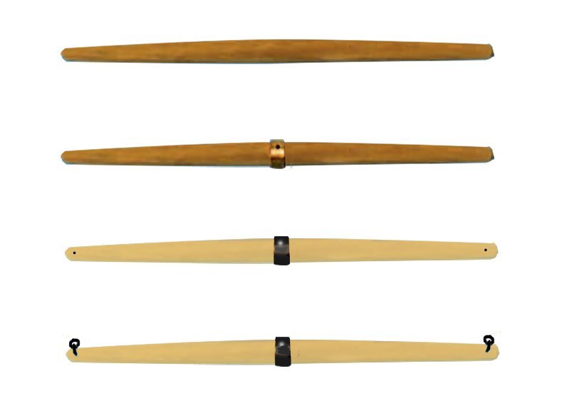
A sheet of 5mm cherry is cut roughly to shape and rounded as shown in the top photo. A strip of 5mm brass is wound around the enter and two holes drilled in the ends which will take eye-bolts. Thee whole assemble is painted ice yellow to match the rest of the chassis.
They can be seen attached to the draw-bar in the following photo
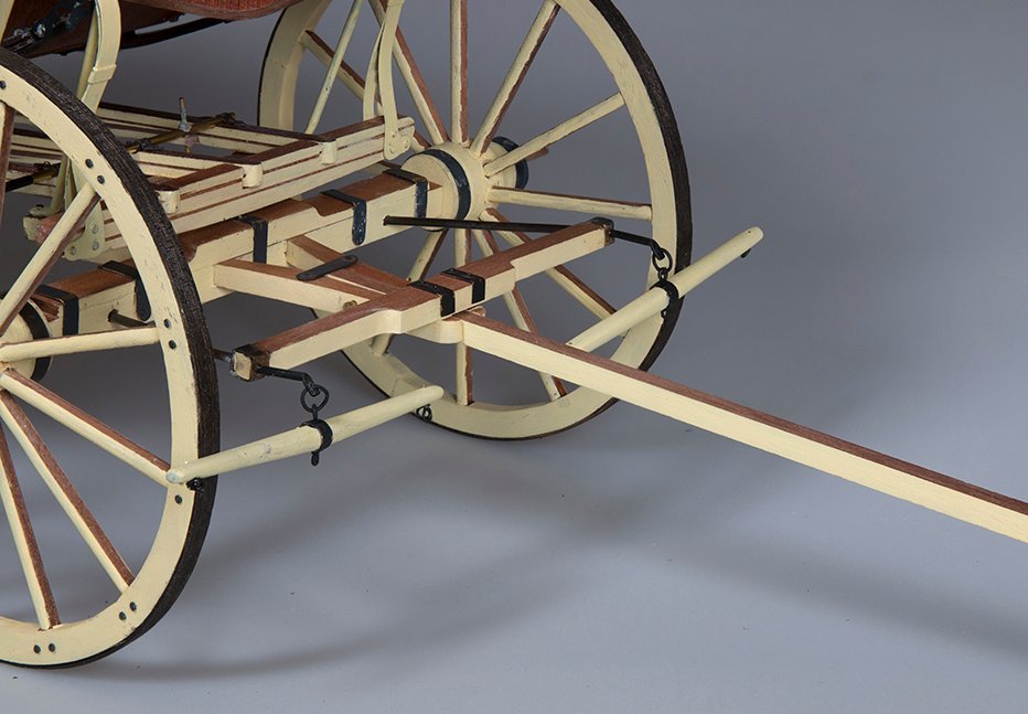
The harness which ran either side of the rear horses would attach to those eye-bolts.
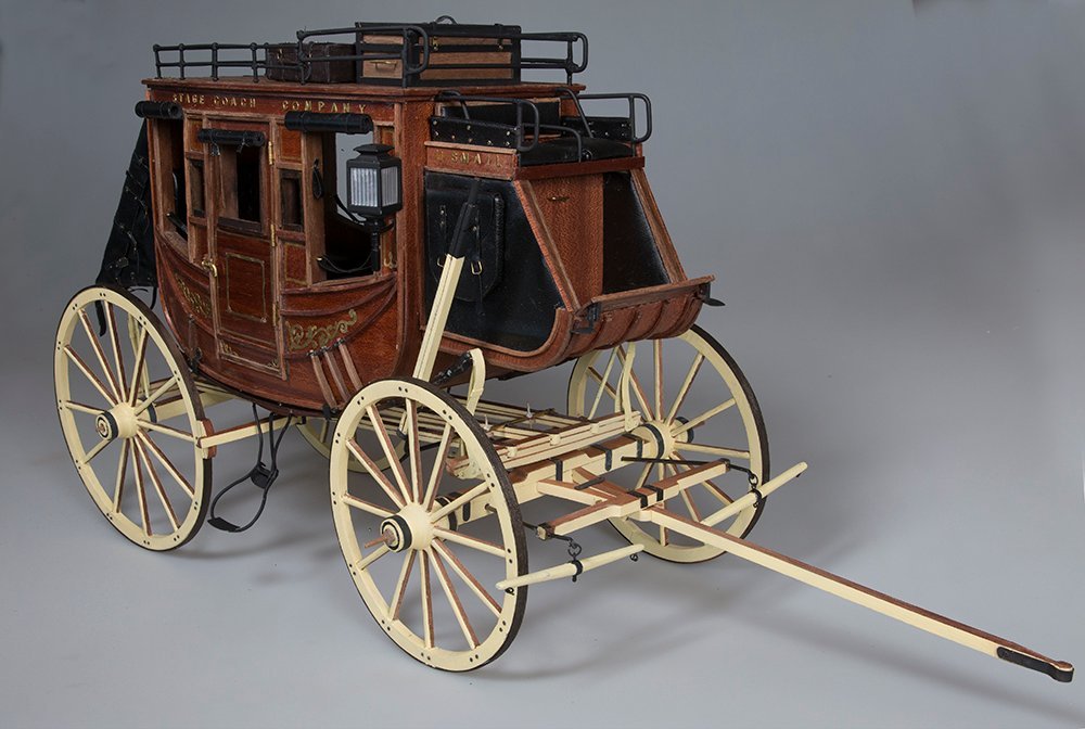
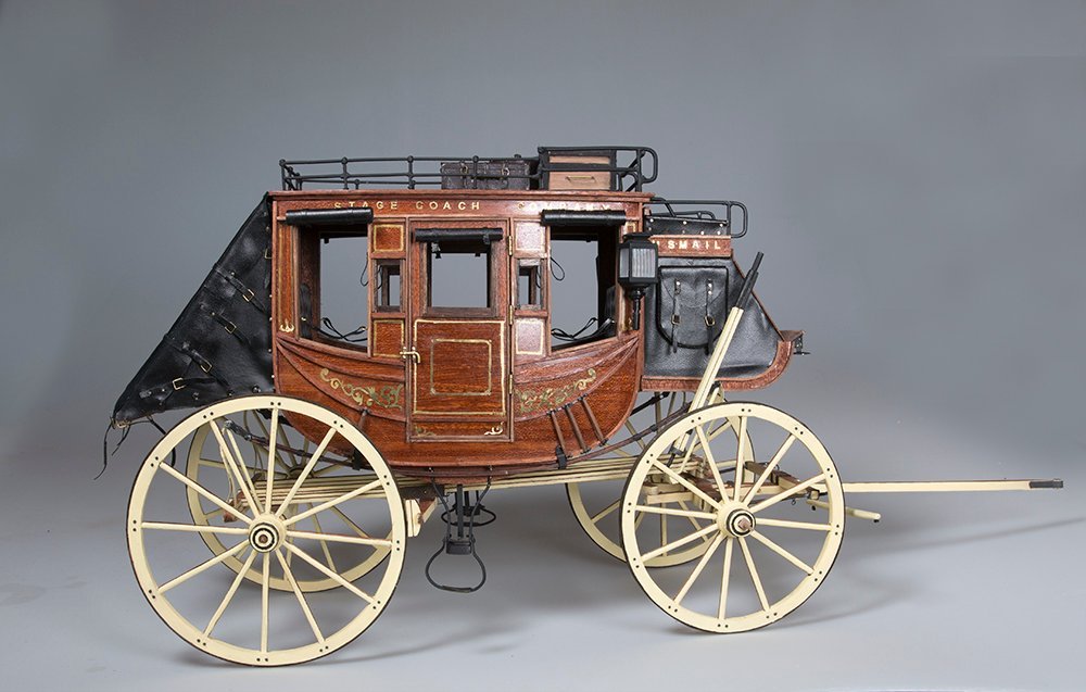
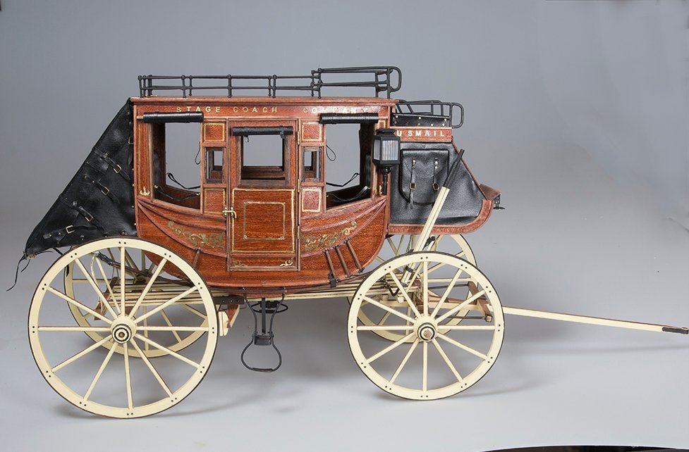
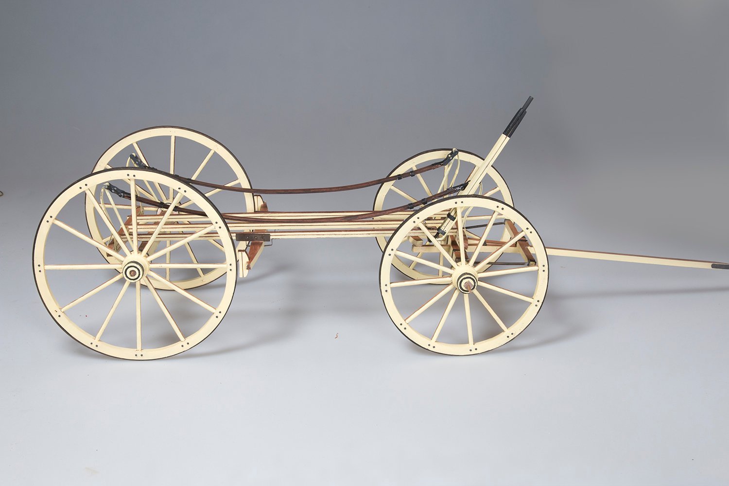
So now with the wheels attached and the coach the right way up it looks like this:
-
On 3/12/2023 at 12:45 PM, CDW said:
Turning out a magnificent piece of history. I admire your work on it.
Thanks for your kind words, CDW and others for your likes. Yes, an interesting period of American History - at least in the case of the Concord coach. Stage coaches were operated in Australia as well by a company called Cobb & Co which was in fact set up by two Americans. They were run initially to the goldfields in the 1850's and later between cities and ran well into the early 20th century since our railways were established later than yours. However, they were of much simpler design than this one. The cabin was simply a straight planked box with no decoration, although they did sport the Concord suspension system.
John
-
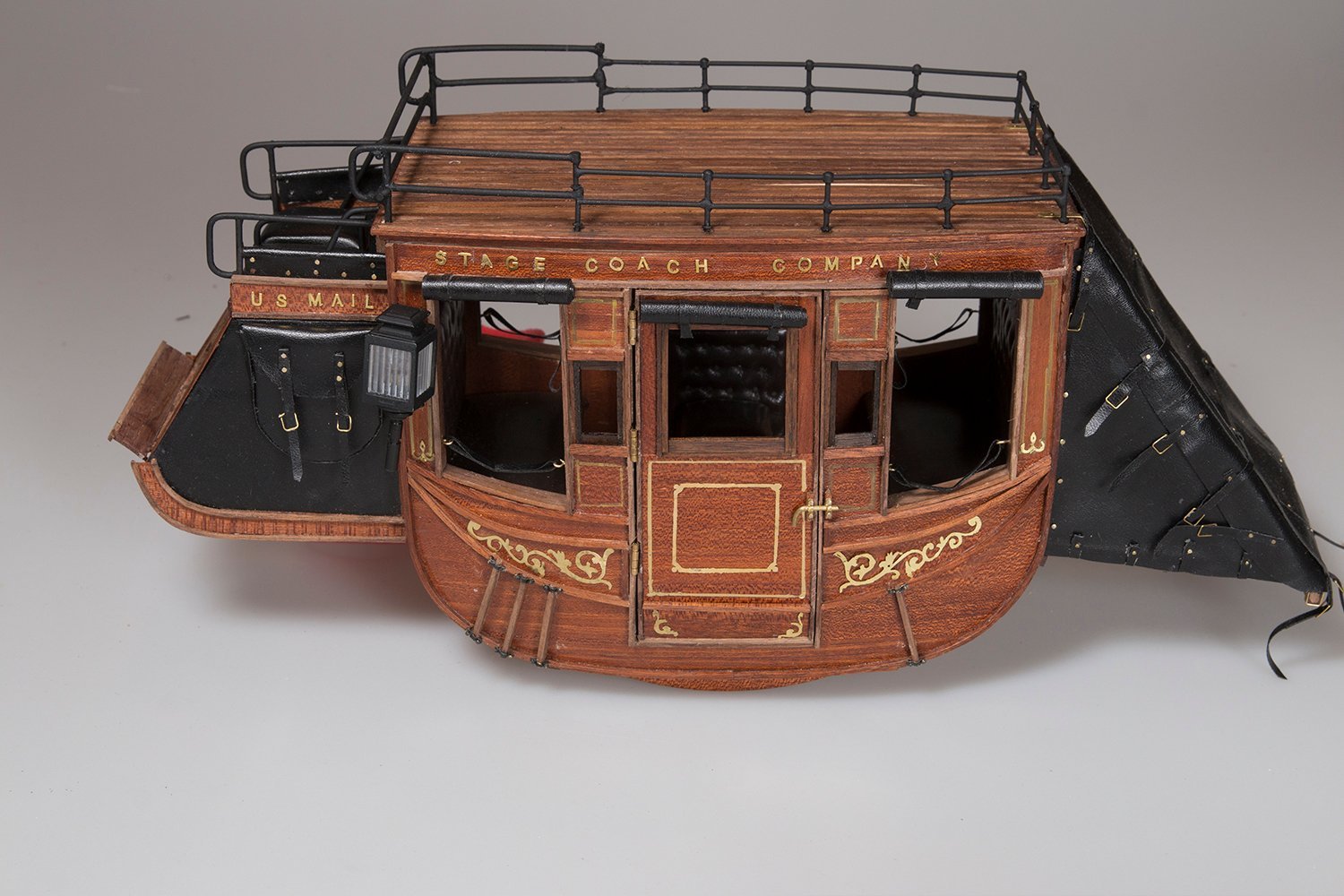
Decorations and Embellishments:
Although these are not in the plans I have seen some pictures of Wells Fargo coaches with scrolls below the side windows and in other places. I have made these before from brass plate for scrolls on ship models but for some reason I had much more trouble this time.
Anyway here is the final result:

Now it is finally time to attach the cabin to the chassis. This was constructed at the beinning of this project. As a reminder here it is:

I have made up four brackets like these to clamp onto the simulated leather straps which constitute the suspension
So next time the chassis will be attached.
John
-
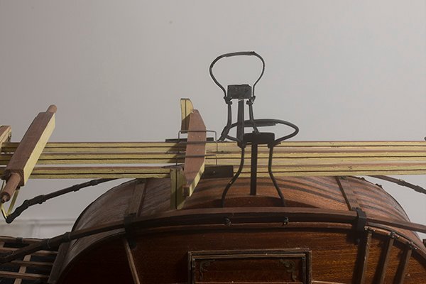
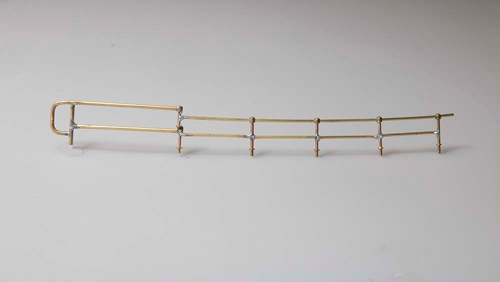
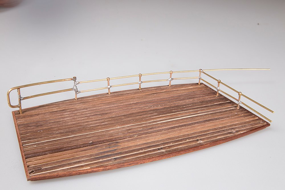
Roof Railings.
Back to modelling after an extended holiday.
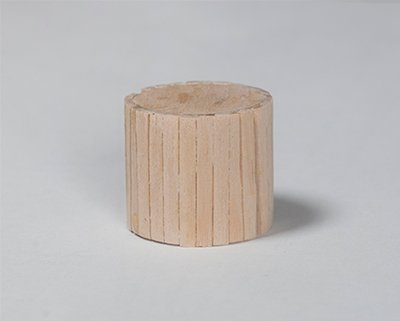
The front part of the railing was constructed as for the drivers cabin using 2mm Brass rod, bent to shape and silver soldered together using a jig to ensure uniformity
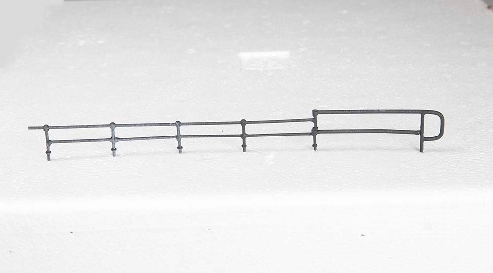
The rear part of the railing was constructed from 1,5 mm brass rod and 1-hole stanchions again silver soldered together:
As the construction proceded the framework was tested out on the roof and holes drilled in appropriate places to take the vertical stanchions:
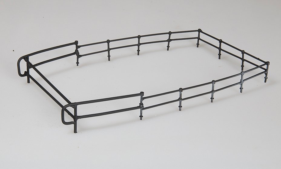
The assembly was painted black. My standard method for brass is to use an etch primer and a topcoat of Humbrol Matt Black.
The final assembly looked like this:
Finally the whole assembly was attached to the roof and secured with a few drops of CA to the in the holes:
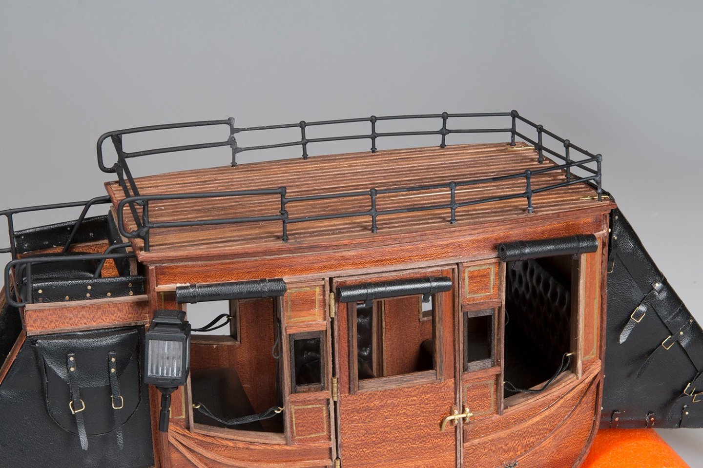
The next step will be to attach the cabin to the chassis. I have already prepared the brackets for this step since the cabin needs to be inverted and this could damage the roof rack once it is in place.
John
-
-
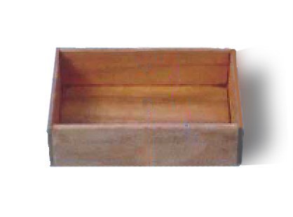
The Luggage Rack (completed)
This has taken me a while to complete due to several distractions (including my tax!)
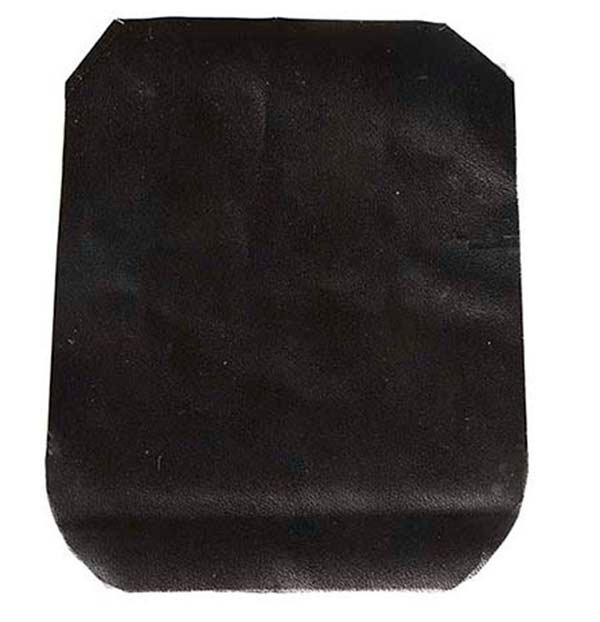
So, the cover for the luggage rack (which actually obscures most the good work done earlier)
Forming the cover starts with cutting a piece of black Nappa approximately 155 X 120 mm
Staps are then attached to these with 5 mm nails
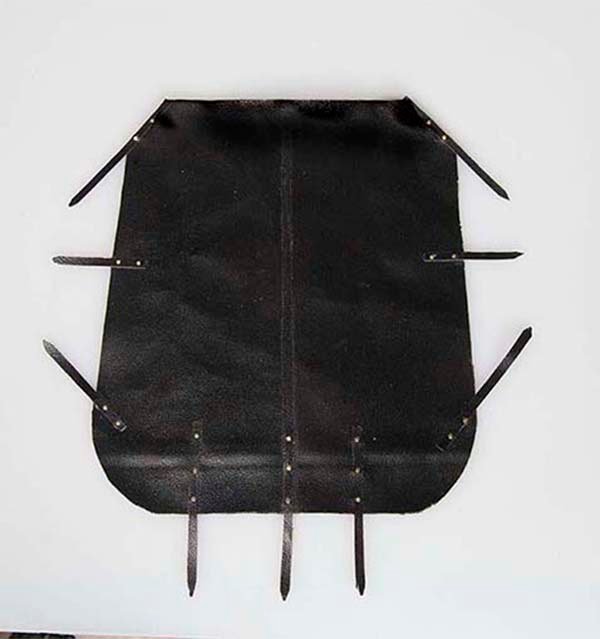
Finally some strengthening bars are added
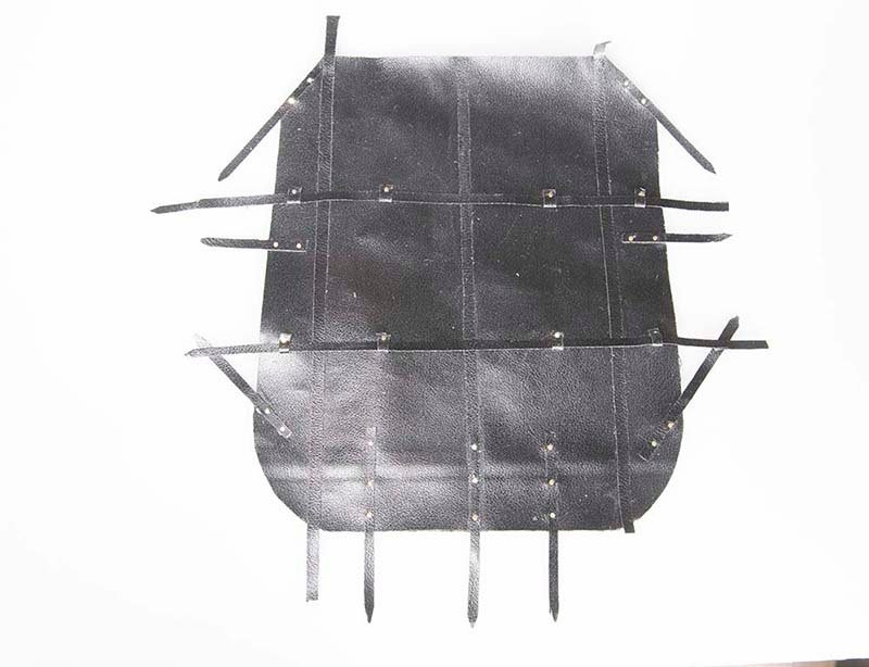
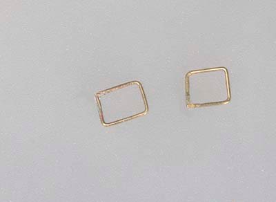
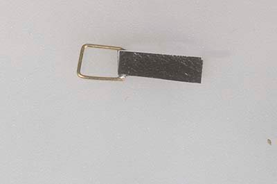
The buckles were made from 0.5 mm brass wire and then a small piece od f Nappa folded over these so that they could be glued to the back of the straps
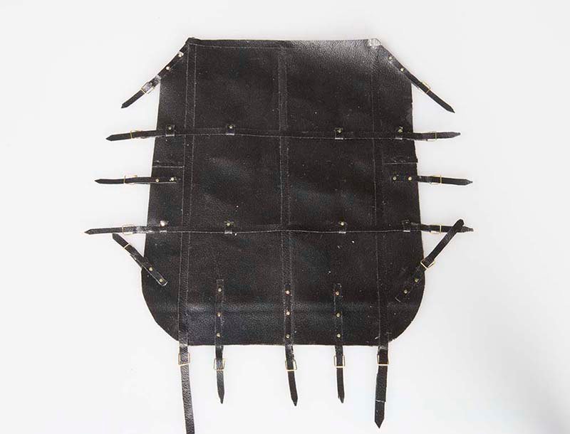
This final cover was then folded over the frame constructed in the previous step
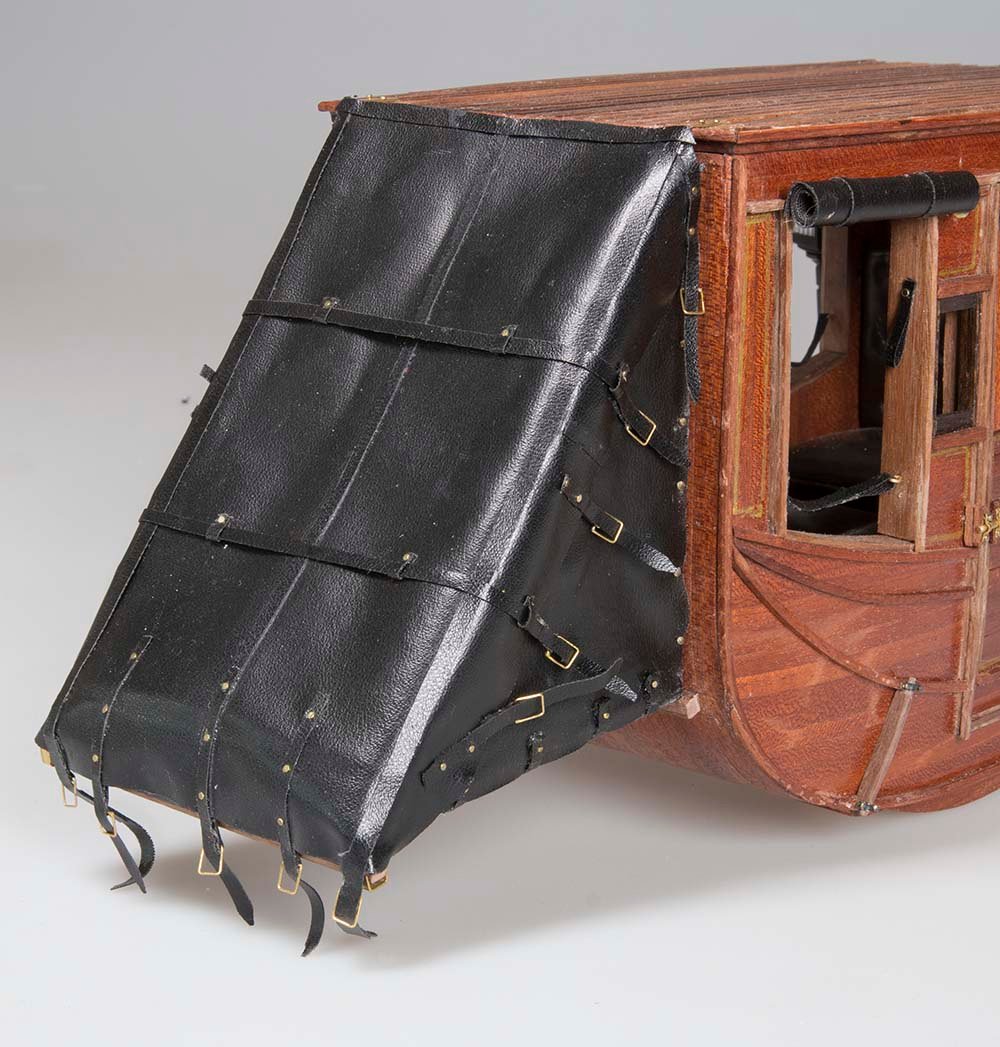
A few bits and pieces such as the blinds became detached during the construction of the luggage raxk so once they are repaired I can proceed with the roof rack
John


Medway Longboat 1742 by bartley - 1:24 scale
in Medway Long Boat - 1742 - Public group project.
Posted
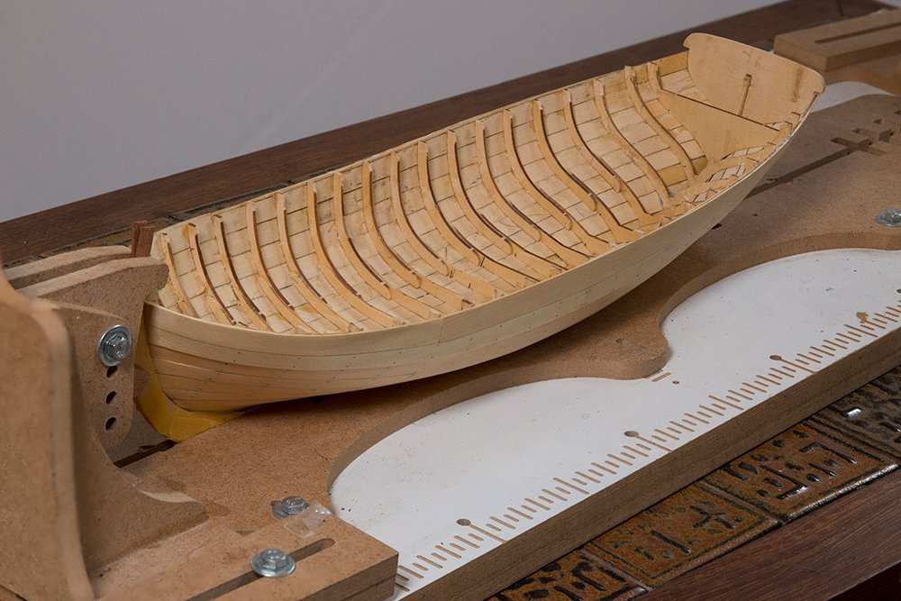
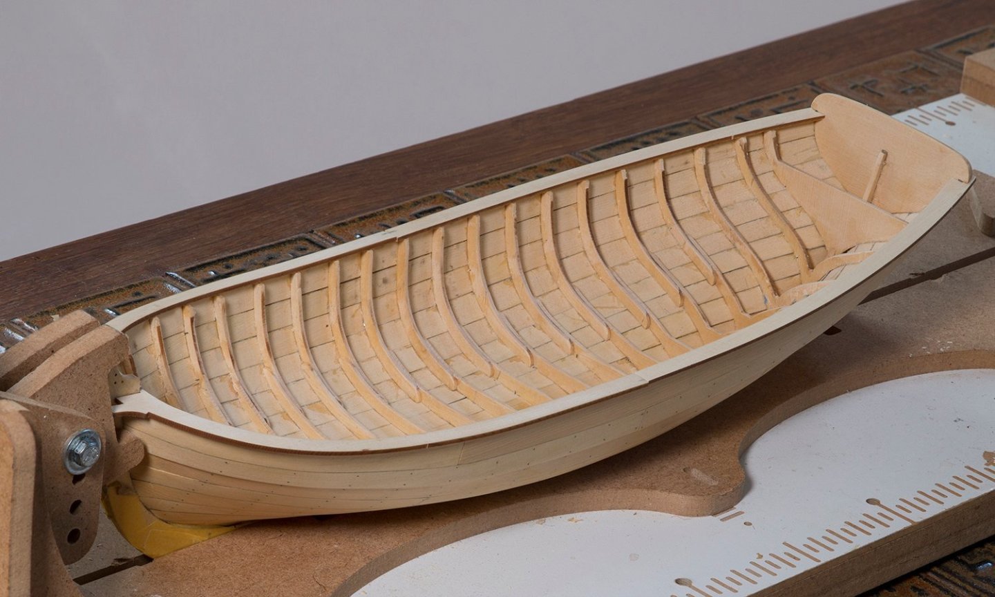
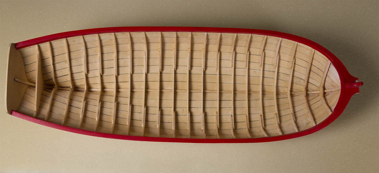
Flooring and Platforms
I found both these steps quite challenging .The flooring has to bend over the frames of course and notching the platforms neatly was also challenging. They are still not perfect but as good as I can get them.
John