

tlevine
-
Posts
1,937 -
Joined
-
Last visited
Content Type
Profiles
Forums
Gallery
Events
Posts posted by tlevine
-
-
-
Thanks everyone for your kind thoughts.
Robin, now I understand what you are referring to. I deliberately left out some of the filling pieces to allow daylight to enter the lower aspect of the hull so possibly some detail could be seen.
-
Thank you Michael, Christian and David. Robin, I have been away for the weekend so am not near the ship. I will take a good look at her tomorrow and hopefully have some type of answer for you. As to the four-legged friend, Sadie is doing very poorly and will probably be put to sleep tomorrow. Thanks for asking about her.
-
-
System, thank you for sharing your picture of Sadie with me. Hopefully my Sadie will be able to pose for the camera soon.
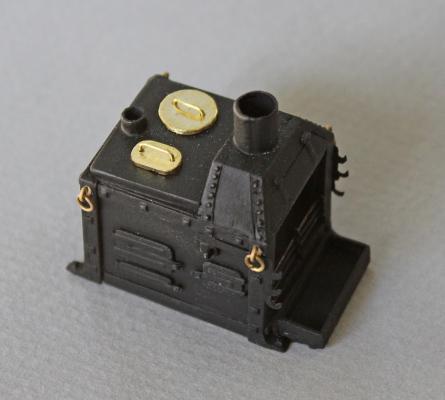
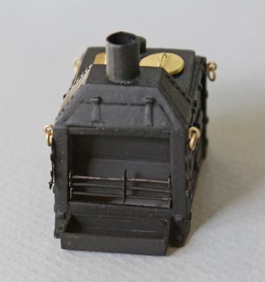
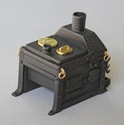
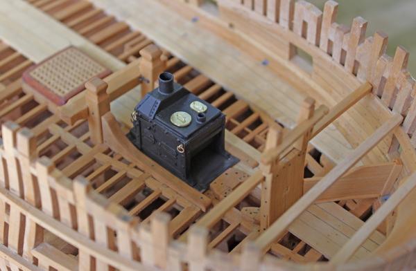
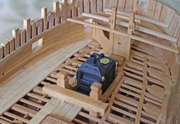
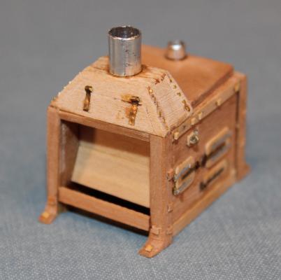
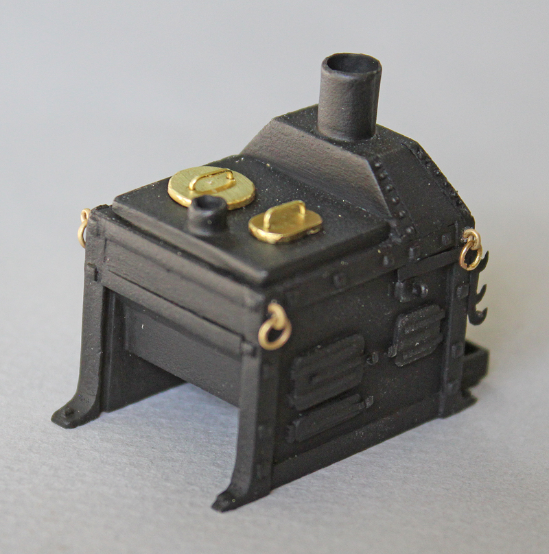
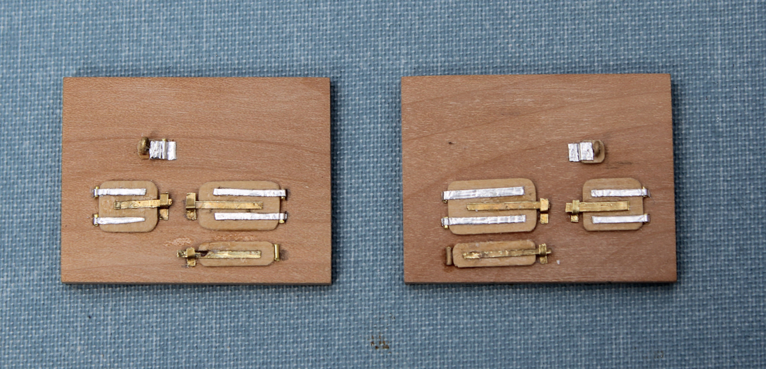
Thank you everyone for your kind comments and thanks for all the likes. The good thing about a recuperating dog is that they sleep a lot. So I got in a little workshop time today. With something as complex as a stove, one needs to ask how much detail is necessary. I decided to make the spit holders, the vertical ash grate (the horizontal one cannot be seen once the stove is installed) and the ash bin. These were made from brass wire and shim brass cut and filed to shape. I rolled the grate rods between my fingers to get that "used" look. I left the ring bolts bright just for some contrast. I may change my mind and blacken them before final installation. They are only press-fit in place. The stove and ash bin sit on an iron platform. I used blackened brass and burnished it to get some color variations. I am considering removing it as the stove visually fades into the black background when viewed from above. One must remember, unless I put a fiberoptic scope through a gunport, the only way the stove will be seen is from above. I will decide in the next few weeks.
- Landlubber Mike, wyz, dgbot and 20 others
-
 23
23
-
Thank you everyone for your kind thoughts. She is sleeping right now so I have a few minutes to post my progress on the stove.
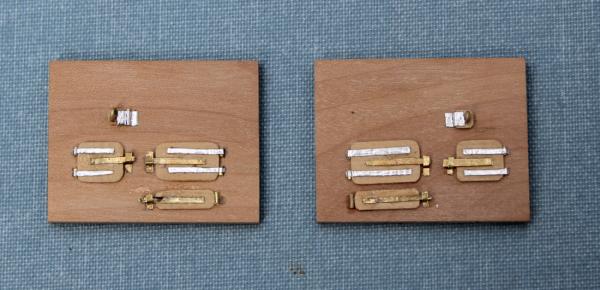
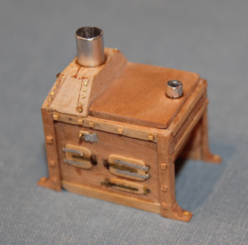
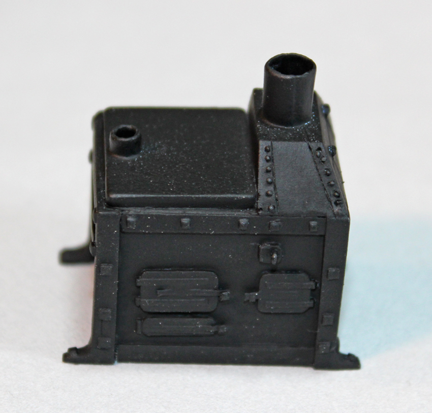
There are a lot of descriptions of the galley stove on MSW as well as in TFFM Vol 2, so I will not belabor that here. The stove is a model in itself and I have been playing with it for a month already. The first decision to be made was what materials to use. This would also drive the construction technique. I decided that this was a detailed "representation" of a stove but that no one would be cooking with it. Therefore, sheet brass was eliminated from consideration except for details. What I came up with is a collection of wood scraps, aluminum adhesive tape and shim brass. The side panels have three larger doors and one small one.
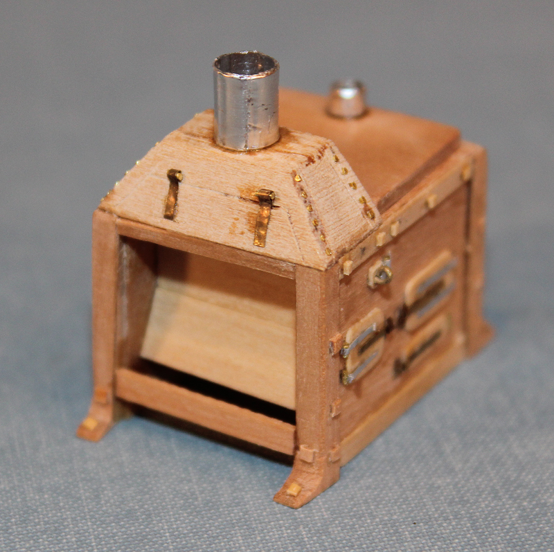
After these were made, a spacer was put in the middle of the stove and the fore and aft faces were constructed. The bolts, cooktop and chimney were added. The rest of the details will be added later.
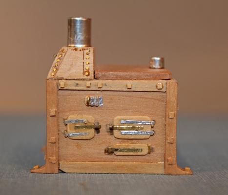
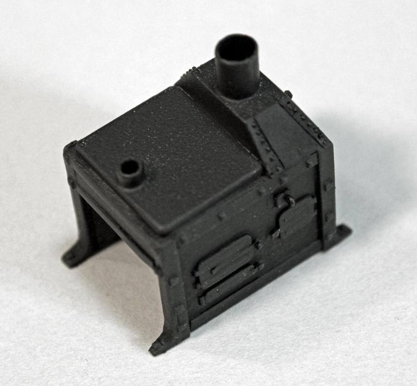
The stove was fit in place on the model and was too tall. So back to square one. I shortened the height by 6" and it fits nicely. It was painted with flat gray primer and flat black (Testors rattle can).
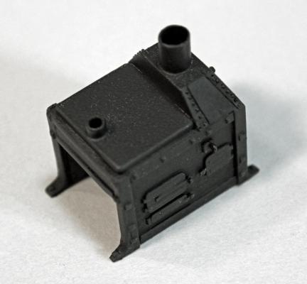
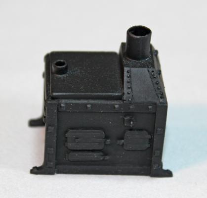
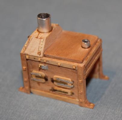
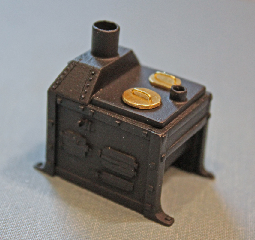
I am sorry the pictures are not of be best quality. It is hard to pick out details on a black object so I played with Photoshop so you could see more than a black blob. The lids for the pots are brass sheet which was drilled for the brass wire handles. So far I am happy with the results. It actually looks like a stove!
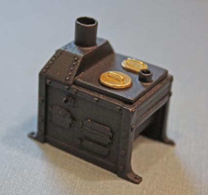
Next up will be adding the details to the stove, making the base plate and installation.
-
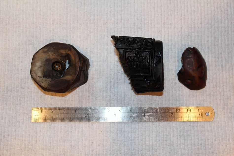
Let me give you an example of life getting in the way. For the last 8 days I have been dealing with a sick dog. To make a long story short, my 12 y/o dog stopped eating and was obviously in pain. Two trips to the vet later, an X ray demonstrated a foreign body in her stomach. Off to surgery we go. She becomes critically ill during the night and a repeat X ray was performed. The overnight vet called to ask why they had only removed one of the two foreign bodies! Back to surgery the next day to remove the other two foreign bodies. She has been teetering on the edge of life all week but decided to eat some scrambled eggs today. They have decided she is depressed and, besides, I am a physician, so she would do better at home. So now it is six medications, each on a different dosing schedule, syringe feedings and hourly walks since (for the docs and vets out there) she is starting to mobilize the 4 kg of fluids she acquired during her holiday. At least she got a complimentary nail clip.
For you savvy dog people out there, the middle foreign body is the Daily Growl, a white plastic squeaky toy that she has not had access to in several years.

- mtaylor, SawdustDave, archjofo and 6 others
-
9
-
-
Or in my case, tripping over the dog and falling into the model.
- Canute, druxey, Landlocked123 and 3 others
-
6
-
-
-
Thanks guys. And thank you everyone for the likes. I am making the rest of the forecastle deck beams and then comes the stove. Looking forward to that with a combination of dread and excitement. There are so many fantastic representations out there that I am just a bit intimidated.
-
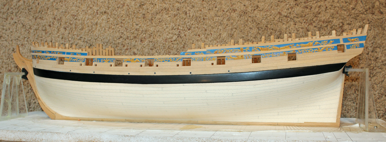
Shipyard time has been tight and will remain that way for a while but I wanted to post a small update. The manger is a triangular area at the bow formed by removable wood partitions. A scupper drains the water that accumulates from hauling in the anchor cables. It fits into a waterway to prevent the water from seeping under the manger wall onto the upper deck.

- albert, dgbot, Wintergreen and 19 others
-
22
-
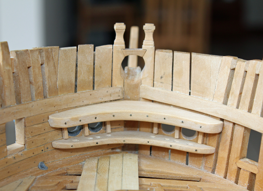
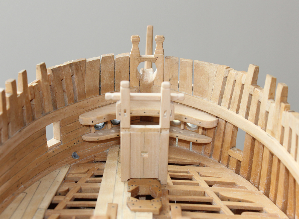
The upper deck hook and the support for the bucklers frame the hawse holes. The support is simply a less robust hook. They are "bolted" to the hawse timbers. I made mine asymmetric because there is no ceiling planking on the starboard side. There are mortises on the top of the support and the bottom of the upper deck hook for the buckler bars.
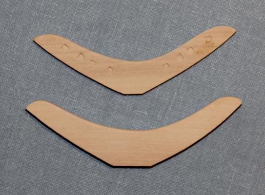
Bucklers can be viewed as removable doors which prevent water from entering the ship through the hawse holes while at sea. There is also a perforated buckler to use when in port to allow the hawse rope to pass. Since I was not installing the bucklers, I did not put the mortises on the upper deck hook. There are three cant posts between and to either side of the hawse holes to support the bucklers.

-
Thank you Robin, Ben and Richard. I will definitely remember that suggestion for the rudder coat. Richard, the rudder will not be shipped until much later in the build. The next project is the upper deck breast hook/buckler assembly.
-
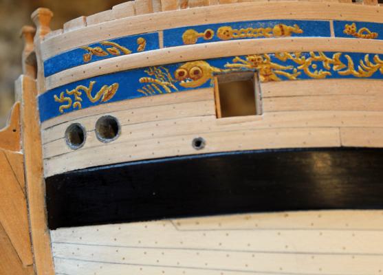
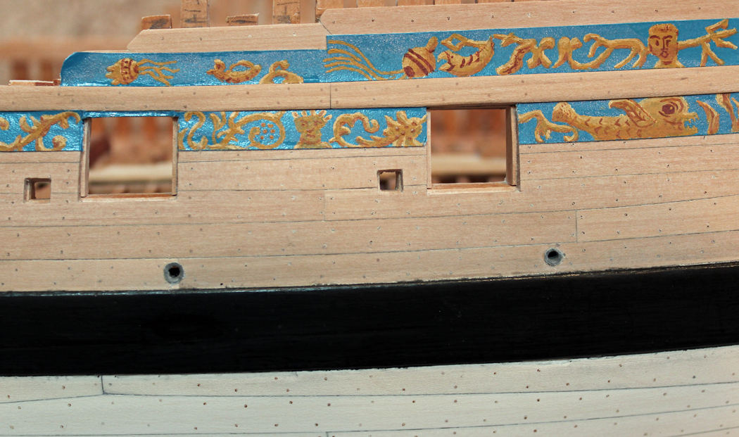
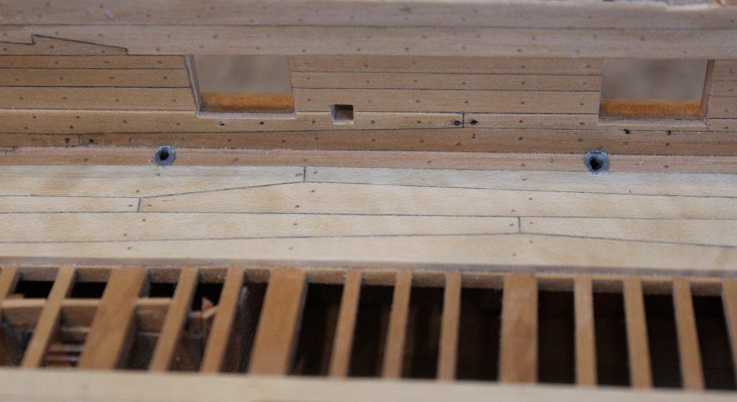
The scupper and hawse hole linings ended up taking much more time than expected. There are five regular scuppers and two larger ones for the manger and the pump effluent. The scuppers are lined with lead sheeting. I tried several approaches including aluminum foil formed over a dowel, self-adhesive aluminum and paper. I ended up making the inner and outer openings with grey paper. The paper and the scupper holes were painted with grey artist acrylic. The shiny appearance of the frieze painting is from the lighting.
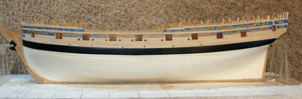
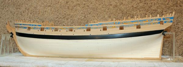
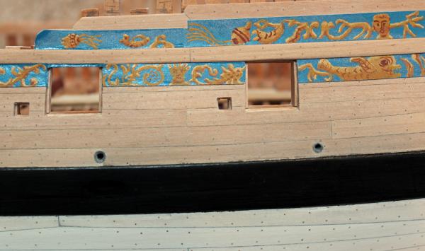
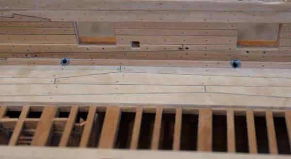
The hawse holes were lined with either lead or copper. I did not want the shiny look of clean copper and so lined the holes with the same gray paper. "Lips" for the lining pipes were added to hide the edge where the paper tube and the wood meet.
-
I had the pleasure of seeing Bob's longboat over the weekend at our monthly club meeting. It looks even better in person than in the photos. I can't wait to see what you find out as regards the rigging.
-
-
Dave, the compliment is appreciated. But I look to Remco's and Dan's builds to set the bar that I strive for.
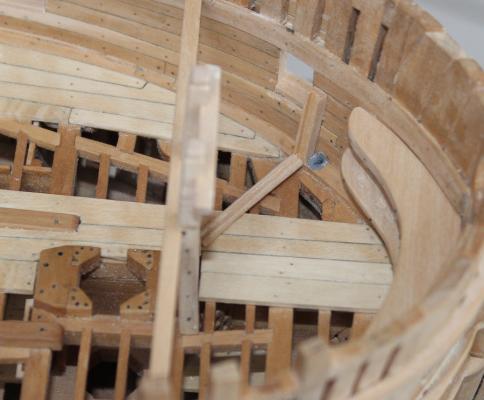
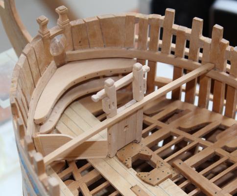
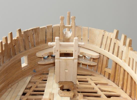
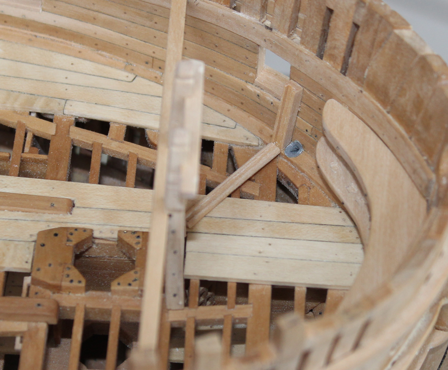
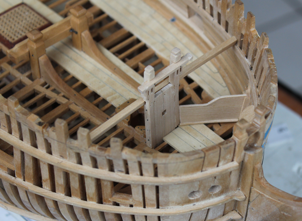
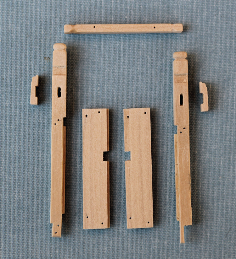
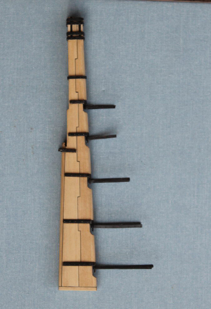
Work on the upper deck will proceed from outboard to midline and fore to aft. I was not emotionally ready to drill holes in the hull for scuppers (and risk damaging the exterior hull) so I decided to build the manger. This is a closed off area in the bow which could be used for livestock but actually helped contain and dispose of water drawn in with the hawse cables. In order to make the manger walls, the supports had to be built first. This means building the fore topsail sheet bitts/bowsprit step assembly. The bitts extend from the upper deck to the forecastle deck and are angled such that the part of the bitts extending above the forecastle deck is perpendicular to the water line. This meant building a forecastle deck beam to determine the correct height and angle. The bitts are notched into both beams. On my model the port side has the deck planking installed. Rather than risk damaging the planking, I trimmed the foot of the bitt to fit the remaining space. The bitts have a sheave above the forecastle deck and a cheek block on the lateral aspect of the bitt. The top of the cheek block has an ogee shape as do the cheek blocks elsewhere in the build. I have not put in the sheaves yet.There is a rabbet on the side of the bitt for the manger wall. On Atalanta, the rabbet does not extend onto the fore end of the bitt so the manger wall extends from the outer face of the bitt rather than the corner. Some of the ships had the upper end of the bitt shaped into a timber head. Atalanta was one of these. The cross piece was rabbeted into the fore side of the bitt.
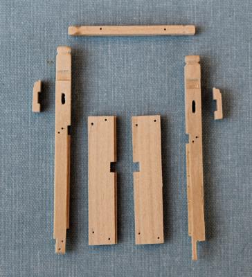
The bowsprit chock is made up of two edge rabbeted planks. You cannot see the rabbet but it makes the assembly stronger. I lightly penciled the joint to highlight this. I temporarily glued the chocks together to facilitate cutting rabbets in the bitts and the aft side of the chock. Although I do not plan on masting Atalanta, I did want the step to be in a reasonably accurate location in case I change my mind later. To find the location for the step I installed a dummy bowsprit, deriving the angle from the plans. This was then marked on the step. They were unglued and the step was cut in using the table saw. I glued them back together and fine-tuned the meeting edges. The chock was bolted to the bitt with four bolts and was bolted to both the upper and forecastle beams. The lower bolts are dummies but the bolts for the forecastle beam will be functional.
After temporarily installing the bitt assembly I noticed that the deck planking in front of the chocks did not extend far enough back. These will be removed and remade to the appropriate length.
- Elia, giampieroricci, Mirabell61 and 23 others
-
26
-
Nobody's planking is perfect. The key is to make it look "correct". Take a look at my stern for a great example of not-perfect. (http://modelshipworld.com/index.php/topic/198-hms-atalanta-by-tlevine-1775-148-scale-from-tffm-plans/page-47) Don't forget, there is a molding at the edge of the planking that will hide some of the discrepancy. I would be concerned that removing too much planking would damage the first layer and you would end up with a whole new dimension of problems.
-
Martin, don't forget that the bands of planking are arbitrary. I would probably lift up the aft 10-20% of the last two rows of planking and taper them to about 75% of the plank width. That would give you room for three rows of planking to attach to the transom. Whatever space is left is your new middle belt.
-
Thank you gentlemen and thanks for all the likes. I should have cleaned the bitt better for the photo but I was running out of daylight. Now I get to return to actual woodworking for a while.
-
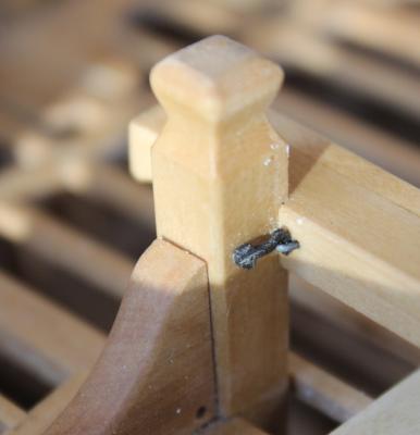
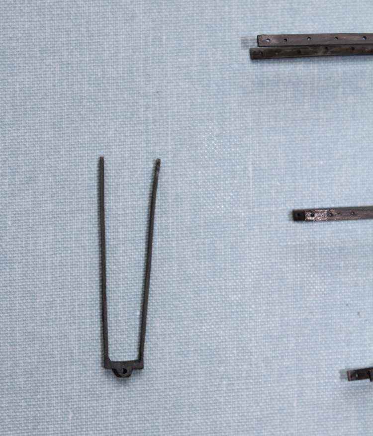
Thanks everyone for the likes. Not much time for the model over the last few weeks but I was finally able to finish the gudgeons. There were made in a similar manner to the pintles, two pre-drilled brass straps connected by brass bar which was then drilled for the pin and filed to shape. Some of the detail is obscured by the blackening. I have not decided yet when to install the gudgeons but will not ship the rudder until much further along into the build.
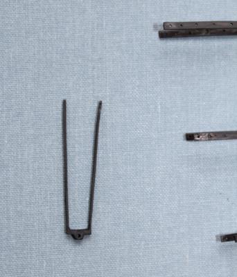

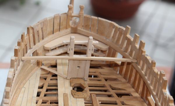
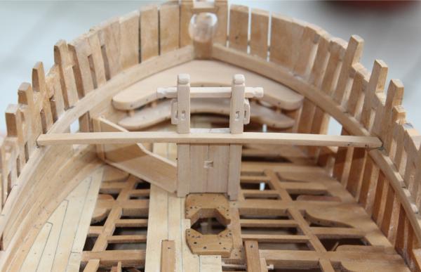
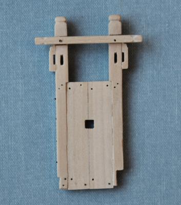
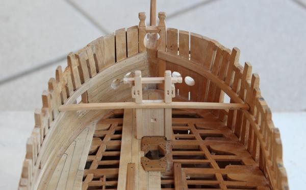
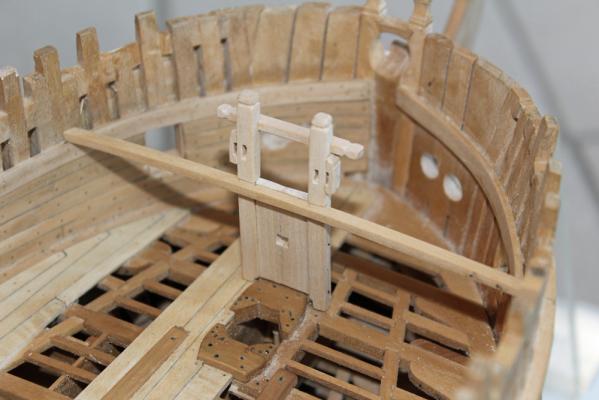
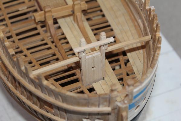
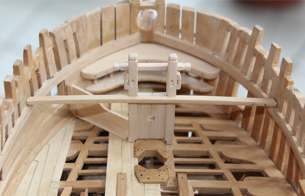
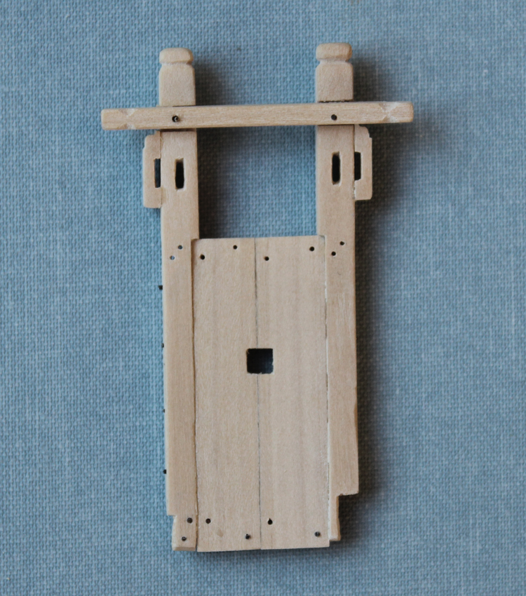
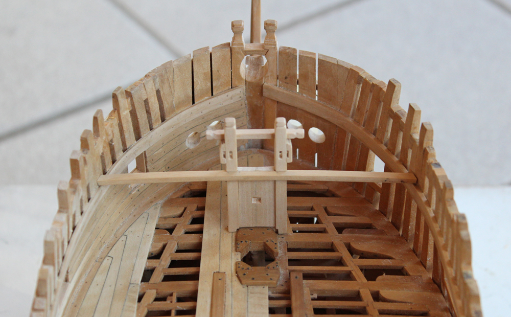
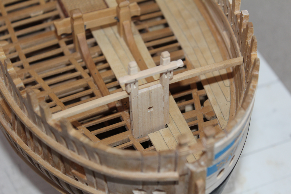
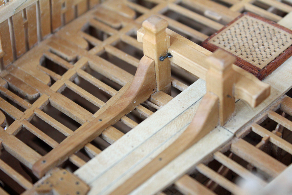
Since I was playing around with metal I decided to make the hook and eye assembly for the riding bitts. The crosspiece is not bolted to the standards. It is held in position with a hook and eye attached to the medial side of the two standards. These are made from 1" thick brass which was filed to shape. The eyes and the bolts are made from brass wire. Sorry for the dust in the picture.

- kees de mol, Krelis, Ian B and 30 others
-
33
-
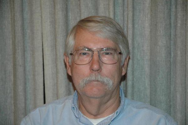
William M. “Mike” Lonnecker.
I am a retired engineer with a degree in Mechanical Engineering (BSME) from the University of Kansas. I worked in Texas and California as a Program Manager and Project Engineer in the Defense and Aerospace Industry until retiring in 2002. I currently reside in Poway (San Diego) California with Sandy, my wife of 44 years.
My interests have included woodworking, flying sailplanes, sailing, hot rodding and modeling all types of “vehicles”. I have been a student of design, modeling and building projects since completing my first plastic model car at age 6 or 7. I now prefer to work on 1: 48 scale ship models of the late 18th century and am building my fourth ship model, The FLY, using David Antscherl’s Swan series of books.
I am a member of the San Diego Ship Modelers’ Guild and serve as Guild Master (President). I am also an active member of the Ship Modelers Association of Fullerton (SMA) and, of course, am a Director of the NRG where I am also chair of the mentor program and am currently mentoring one member. I enjoy sharing my modeling and machining skills with other modelers and regularly give demonstrations at club meetings and invite other members to my shop to work out difficult problems or aid new modelers with their projects. My MSW screen name is Mike.


Cutter for HMS Vulture by Dan Vadas - FINISHED
in - Build logs for subjects built 1751 - 1800
Posted
As I recall, the height of the sheer was incorrect. When I get back home later this week I will look at my plug. Greg should also remember the problem. I would check the height of the plug against the plans.