

tlevine
-
Posts
2,020 -
Joined
-
Last visited
Content Type
Profiles
Forums
Gallery
Events
Posts posted by tlevine
-
-
-
I used this series of articles to build my Victory. They are very well done but there are some errors. I double-checked everything with other sources, such as Longridge. There is also a compilation of the articles entitled "How to Build a Masterpiece in 1:96 Scale." The content is identical although the photos are of slightly better quality.
-
Danny, the build is beautiful and the cutaways are a great touch, especially the chains in the log pumps. Did you have an extra set of the photoetch for the chains and sprockets?
- CaptainSteve, Bobstrake, Canute and 3 others
-
 6
6
-
-
Dave, where's your build log? Beautiful model.
-
-
-
-
-
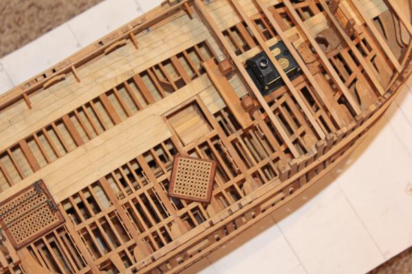
Although it may not look like much, most of the free time this weekend was spent making and installing ringbolts and eyebolts. All the iron work was made with 20, 22 or 24 gauge brass wire. The eyebolts and most of the ringbolts are silver soldered closed. I ran out of propane and it was just too cold (-4F) to want to run out to the hardware store.

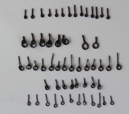
There are five stopper bolts. These run through the binding strake just lateral to the fore hatch. The top tackle eyebolt is located in the binding strake at the level of the aft end of the after hatch. The gun tackle ringbolts are used to haul the guns inboard and are also located in the binding strake. The stopper bolts serve double duty in this regard. There are four eyebolts in the main mast partners. Finally, there are three ringbolts in the bulwark at the level of the main mast. The breeching ringbolts and port tackle eyebolts will be installed when the guns are rigged.
While there is still access to the inner bulwark I installed the simulated chain and preventer bolts. These bolts secure the preventer plates to the hull. First, stub masts were inserted and a string was used to determine the angle of the stays as they intersect the hull. I marked this on masking tape. The locations were then marked internally and installed using 1.5" bolts.
-
-
Martin, if you ever saw my feeble attempt at carving you would understand completely.
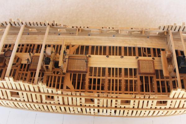
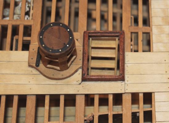
There are two ladders between the upper and lower decks. The fore ladder is located under the fore hatch and the aft is uncovered because it is protected by the quarter deck. In order to install the fore ladder, I had to pry off the fore hatch. The ladders are simple structures. The key is NOT to do what I did and reverse the direction of the treads.
With the hatch replaced, it is almost impossible to see the ladder.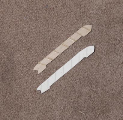
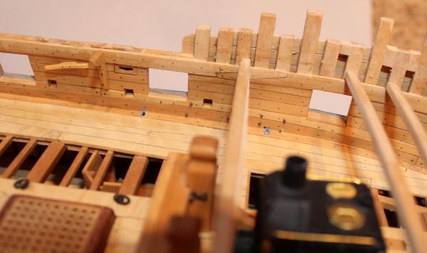
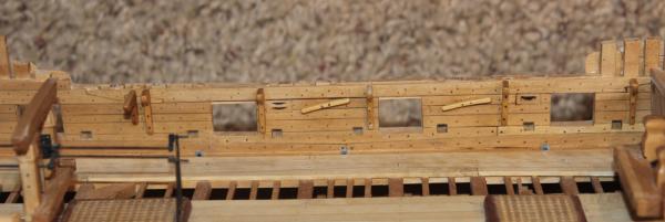
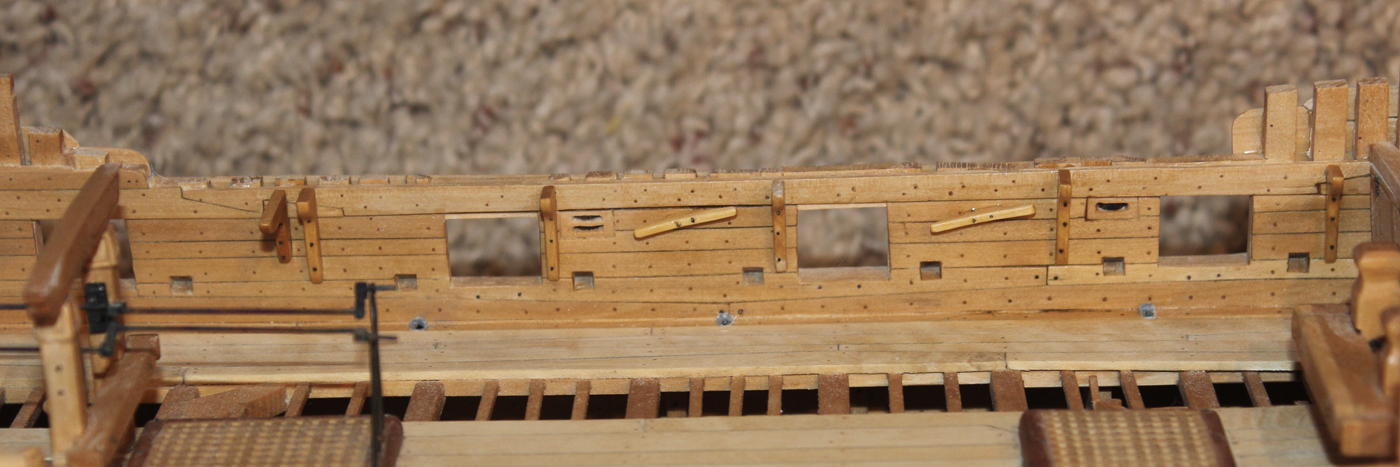
There are two range cleats in the upper deck bulwarks for the fore braces and the main course tacks. These are fastened through the side of the ship by two bolts. I considered doing this except the bolts would have gone through the frieze.
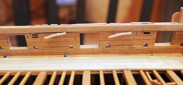
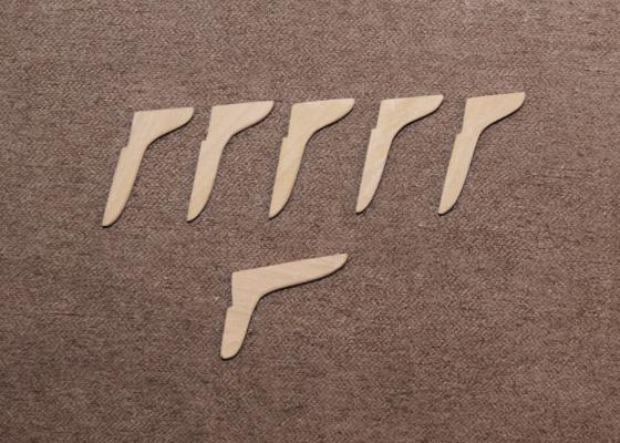
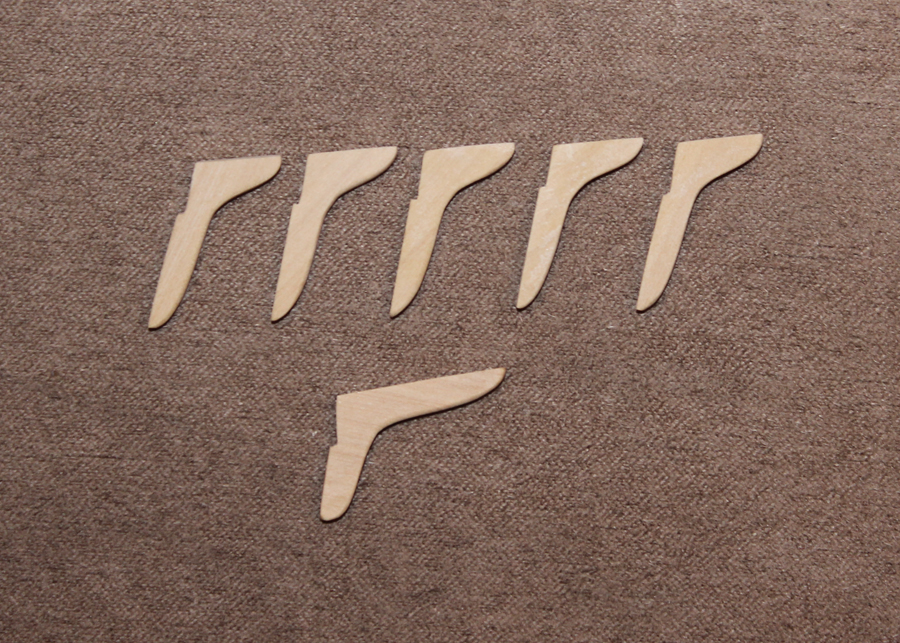
The knees to the gangboards are also installed into the upper deck bulwarks. The aft knee is for the fixed gangway and the five fore knees are for the gangboards. The aft knee has an athwartship arm of 2'9" and the other knees have an athwartship arm of 1'5".
-
Your work is the epitome of perfection. No one would know those bolts are 1/4" too large unless you told them. But of course you will always know. As I am less of a perfectionist than you, I would leave it since overall the construction is very sharp and use that time to move forward rather than look backward. My TFFM is full of sticky-notes for "the next one".
-
-
Your work is too fantastic to simply give it a "Like".
- Piet, Stuntflyer, druxey and 1 other
-
4
-
-
Thank you, everyone for the likes. Well, Druxey, I gather those central panes are typically darkened? How dark would you recommend? I was afraid that you were going to tell me the acanthus leaves were carved. At least that is a smaller project than some of the other carving which will be required.
-
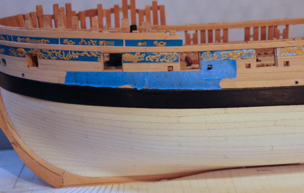
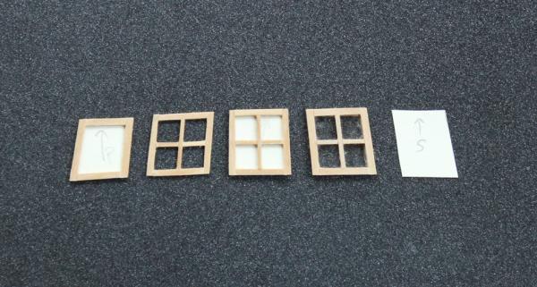
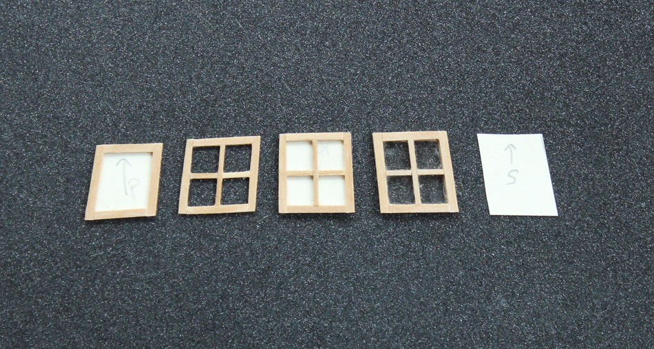
The next items to make are the windows themselves. Since these are not structural I made them simply by edge gluing rather than finger jointing the stiles and rails. Also, the mullions are not half-lapped but are simply edge glued as well. The glass is mica. I was very surprised how well the glue adheres to the mica. The first picture shows the sequence of construction. First a template is made of the window opening. The stiles and rails are glued to the template. The mullions are then added. The template is peeled off the framework and mica is put in place. Finally, the inner frame and mullions are added. The center opening was not glazed as it looks directly into the back of the rudder trunk.
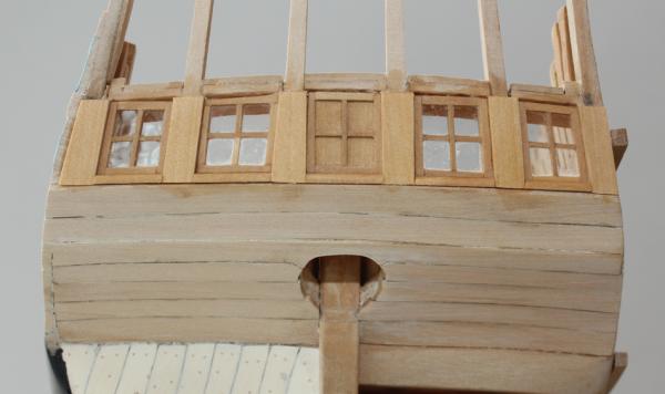
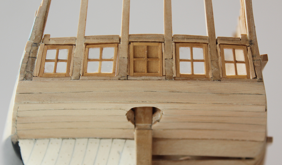
The windows are glued in place. The small gaps will be hidden under the munions and decorative moldings. The discoloration of the wood of the upper and lower counter is from internal finish seeping out between the planks. This will not be a problem after the external structure has a coat of finish.

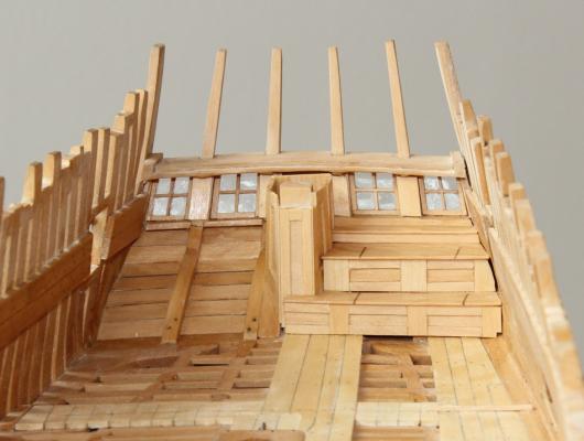
The munions are trim boards between the windows which hide all of the internal structural components. External to this, the plans show a column with acanthus leaves. I cannot tell from the plans whether the leaves are carved or painted. This will be added when the rest of the stern is completed. One of the central munions is not the same shape as the other five. After careful consideration and a few choice words I determined that the only way to correct the problem would be to rebuild the entire stern. And that wasn't going to happen! It looks worse in the photo than in real life. Once the decorative trims and columns are added I do not think it will be very visible (except to me).
These windows open inwards. There is a quarter round sill which acts as a stop to prevent the window from opening outward.
- Jeronimo, Mirabell61, cabrapente and 22 others
-
25
-
Druxey, Nils, albert and Remco thank you for your comments. And thank you to everyone for the likes. The next thing to tackle will be the windows themselves.
- albert, Mirabell61 and mtaylor
-
3
-
Seeing your build brings back a lot of memories, both good and bad. Peregrine was my first wooden ship model, completed in 1983. I did not have a clue what I was doing and the instructions were of no use. I even bought an Italian dictionary to help translate them. You are doing great. Keep up the good work and above everything else, enjoy yourself.
-
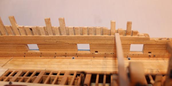
At this point, all that was necessary was to pop the side frames off the stern timbers and apply new ones that extended the full depth of the timber. An exterior stop will be applied after the window has been installed. Thanks again, Danny.
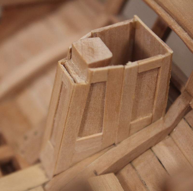
The rudder trunk extends from the fore face of the stern post to just aft of the opening for the rudder. There is a gap between it and the center window. It is trapezoidal in shape. Because of the angles involved and the shape of the lower counter, templates were used to get the correct shapes for the pieces.
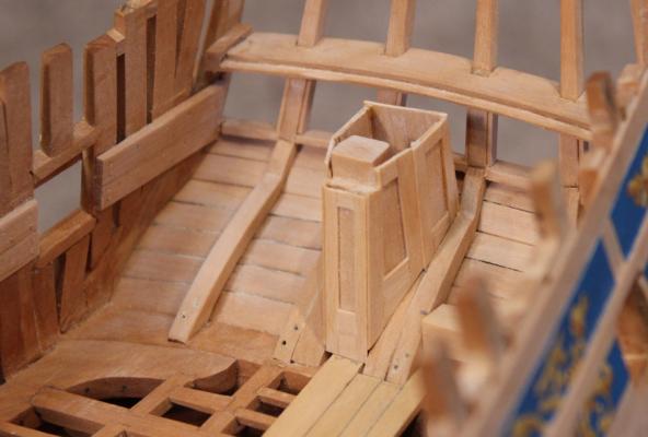
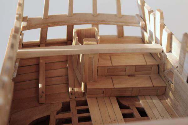
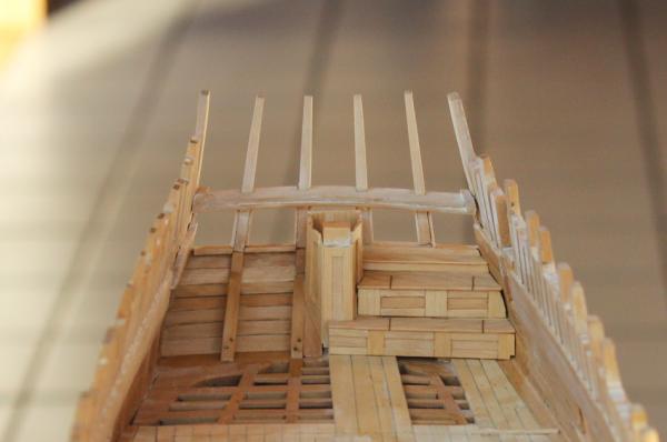
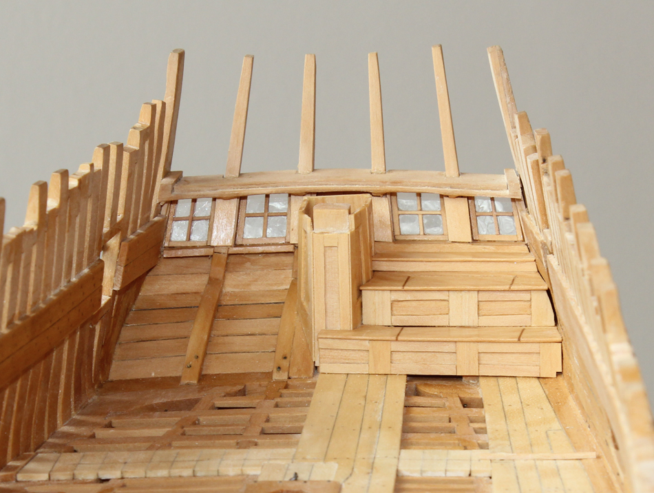
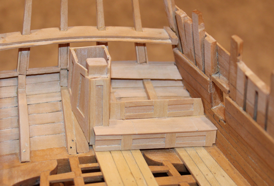
Lockers ran the length of the aft wall of the cabin. They are deep enough to provide additional seating space. On Atalanta there are two tiers of lockers and a shelf above the upper locker below the level of the window sill. I have chosen to model only the port lockers, leaving the starboard framing open.
The first step was to develop a template for the profile of the lockers and counter. This was taken off the plan. The lowest vertical element was made first. Paper templates were made for each piece of the assembly. I glued the vertical stiles onto the template and then installed the horizontal slats. After it was dry, I peeled off the paper and glued in the recessed panel. A cleat was installed on the blind side to stiffen it and give a wider gluing surface. Finally, it was glued in place. The horizontal element needs to be supported at the stern timbers. I inserted wedges between the timbers to provide a gluing surface. In the pictures it appears that they are not at the same height or angle. This is an optical illusion which is occurring because the deck curves but the locker is horizontal.
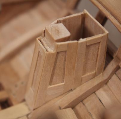
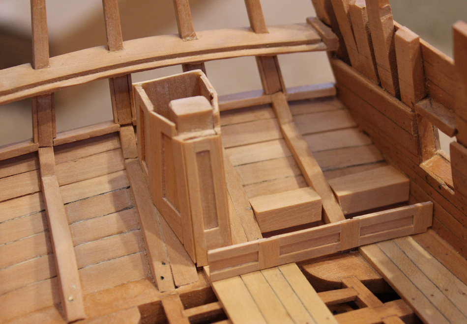
I had a choice at this point to either make a functional locker door and frame or simply make one piece and draw the door in with an #11 blade. I chose the latter. This actually makes the outline of the door stand out better than if I had made it in two pieces. Be sure to carry the incision around the fore edge of the door. It barely shows until the finish is applied. I toyed with the idea of having one of the lockers open and filled with rolls of maps but decided against. None of the other rooms have elements that would have been brought on board (with the exception of the hammocks) so for consistency I left the lockers closed. I will not furnish the space for the same reason.


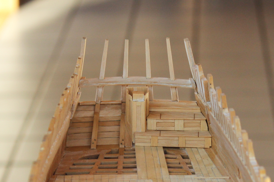
The second vertical element starts approximately two inches behind the edge of the door. The panels are shorter because of the rudder trunk. I have also installed the interior upper counter plank to act as a gluing surface later.

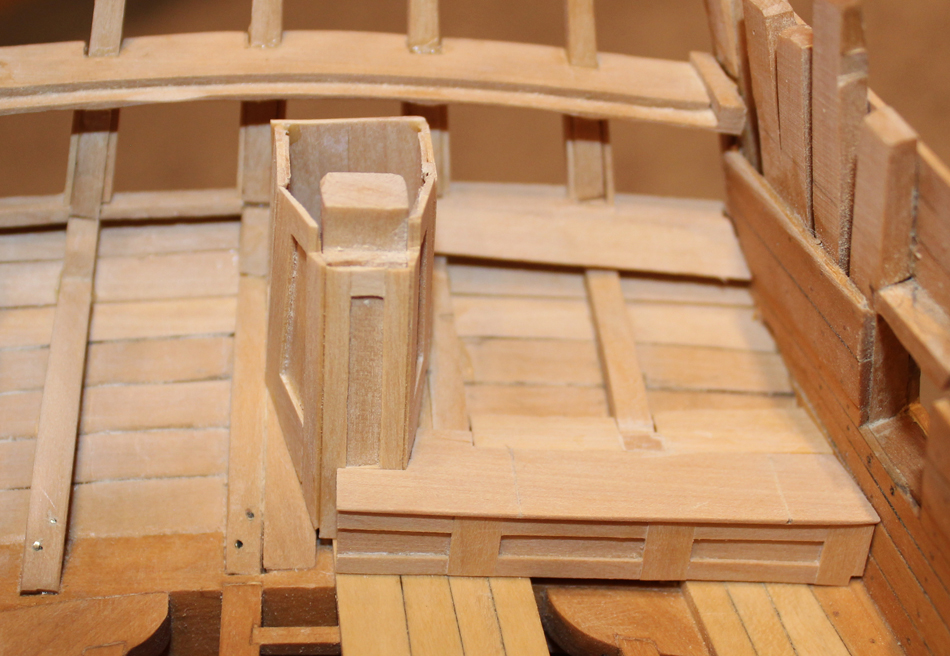
The second horizontal element is installed, followed by the third vertical element and the shelf. Because of the height, the third vertical element has no ornamentation. The last two pictures show how the outline of the door stands out after a finish is applied. I still need to install hinges. In the last picture, the angles still look "off". This again is a function of the sloping floor and the horizontal locker door, combined with the angles of the hull planking and my bad photography skills. In real life it looks correct.
-
-
-
The use of wire pegs to secure the quarter gallery framing is brilliant.
- mtaylor, Obormotov, michael mott and 2 others
-
5


HMS Atalanta 1775 by tlevine - FINISHED - 1:48 scale - from TFFM plans
in - Build logs for subjects built 1751 - 1800
Posted
I am stunned to realize that I have not posted on this build log for almost two months! Well, work and life just have a tendency to get in the way. I have started working on the armament. There are sixteen cannon on Atalanta. I will be showing the eight on the port side. This project has taken three times as long as I had anticipated and is not over yet.
The first step is making the carriage side. I laminated strips of costello the correct thickness together. The various steps were milled into the laminated blank. The curved under-carriage was roughly milled and the filed smooth. The pictures show the blank from different angles.
Holes for the various bolt were drilled while the blank was still intact for stability.
The remaining parts of the carriage (axles, wheels, bed) were made. There was nothing complicated about any of these parts. The front and rear wheels are different diameters. These were turned down on a lathe and then cut off with a razor saw to prevent chipping.
I made a very simple jig to facilitate assembly. On the left side one can see the two size holes for the wheels. The center hole for the axle was drill by inserting the wheel into the jig. This helped prevent splitting.
The next pictures show various views of the partially completed carriages, including various rings, the bed bolt and the wheel pins.
Finally the quoin and the rest of the bolts were added. The quoins were hand carved.